

Page 1
INDUSTRIAL
SEWING
flNEST
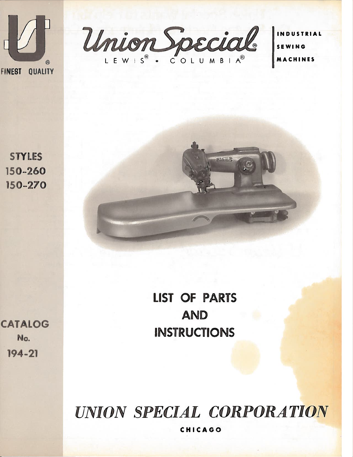
STYLES
150-260
50-270
QUAUTY
LEWIS.
COLUMBIA
MACH
INES
LIST
OF
PARTS
AND
CATALOG
No.
194-21
UNION
SPECIAL
INSTRUCTIONS
CHICAGO
CORPORATION
Page 2
Union
Special
Wants
Helpbu
to
(mmmiii
Slim
educe
ynum
system
to
and
a
pats
Machine
gm
(lmuon
mi’
lkomnm
requaed,
and
on
Request
233).
out the
fillsinthe
Maintenance
kepiir—prnmme
mirmmntenmnms’
your
Special
maci
ku’epmimg
The
lust
2.37)
their
cost
The
second
repair
costs
Card”
When
top
Cut
sewmmmj
help
imiVi’iitniV
systeom
loi
the
card
are
system
a
of
time
machine
a
Sewing
ml
is
nllm’nnil
lmma(lmmnm’
spot
immailnimmi’s
syst
Records
nm,mctninu’s
ctnllmm
suiqgu’sts Iwo
systemnm
iismmng
utilizes
each
sewiii!J
pulled
is
entered
ill
is
normally
is
desired.
(Form
234),
requires
“Repair
Request
repair
work
the
tsvo
(‘iii
or
inexls’i
s
vanations
‘‘Mactmiimc
a
mniactninm’
from
ttie
QJ4’m-r
_mmrmua
mcOm
Two
and
n,mm
na
mk’imaimim’
1511111
to
sla’i’mI
‘Iron
mm
maRts
the
spaces
used
record
“Machine
a
service,
Card”
started,
is
ii
‘y’tm’mrm
ml
costs:
iimg
ihimnmmnmilly
mnmitimim’
lie
ed
I
oidei,
‘imniplt’
of
a
1
miovidm’d
Mammmtc’nainc
in a
plant.
tile
and
fbi-’
piovided
231
when
more
cards
are used:
the
and givesitto
the
Machine
iiiijmnmiml
lii
11111
rcmnrd
a
‘pails.
mnilntemil
lim’lj)
In
by
Union
When
rm’pan
and
kr’m’ping
in,nnlm’mmimn
logIn
n)m’iatni
ttii’si’
Sl)t
niaimmtm’n,mn
Sla’ciil.
Record’
a
im’paii
date,
ttmecaid
caid
pails
is
of
-j
—
-
detailed
Repair Record”
forelady
parts used
a
“Repair
or
foreman
mechanic.
a
and
information
(Form
their
nid
s
cdii
piohli’mrms,
is
used,
iled.
fills
He
cost,
Maintenance
llii’mnmirplc’lioii
cit
abrini
he
needed
for
when
inventory
local
md
Mactnne Repair
Wliste’vt:r
im’dml(
t’
to
Repair
ami’a’d
wconmmnends
system
downtime
Part
WInk’
mnally
by
toy
Excessive
elinrinated
spare
the
For
free
Union
needless
record
rnutiime
parts.
parts.
is
overall
sample
lists
system
Inventories
keeping
high
that
each
niacliimie
with
Theme
Long
kept
for
Special
tire.
Recoid
is
namirtr’naimcm’
inaintenmimee,
repairs.
manulactumem
of
type
downtimmme
orderly
an
isnolonger
waits
to
a
savings
copies
varietyofthe
a
Representative
3liisd,rti
‘‘
keptmmtIme
used,
tells
To
sewing
for
minimum.
are
the
of
Costs
istlremm
office.
irmanamlenrent
usts.
nminagenient
it
does
littletohelp
alleviate
in—plant
considered.
this
s
establish
machine
and
wasted
inventory
a
needtocannibalize
deliveries
The
costofa
c
-
machine
most
popular
or
write
tiammsteried
now
has
which
situation,
a
formal
they
operate.
hours
of
are
avoided and
parts
::
O0su
record
cards
machines,
direct
to
ttie
an
niacliines
reducethe
Union
parts
by
mechanics
the
most
other
inventory
and
to Union
si
invaluihl’
o’mimmi
downtime
Spv(
iventum
i
commnnly
machines
machine
spare
contact
Special.
isil
ml
y
iii
small
is
part
your
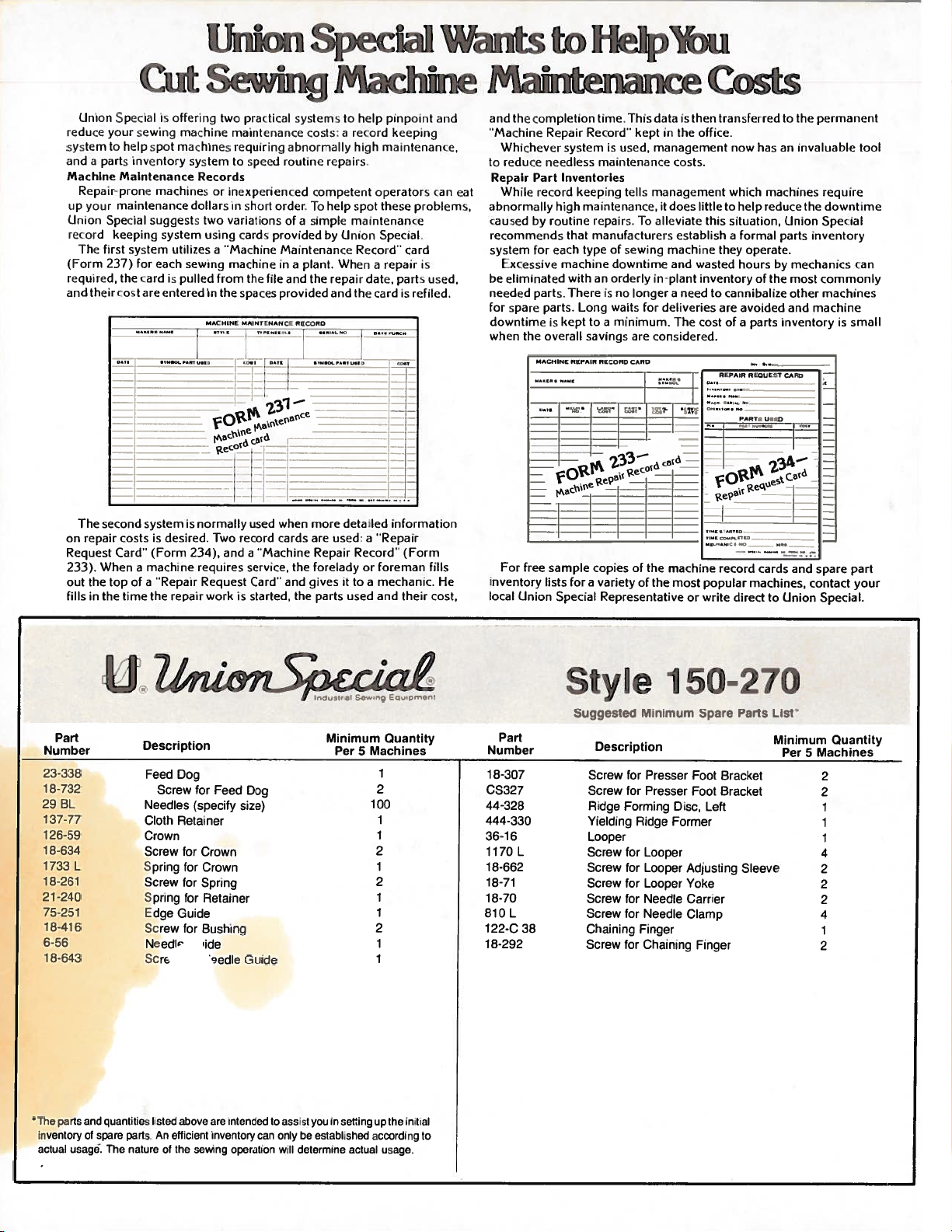
Part
Number
23-338
18-732
29
BL
137-77
126-59
18-634
1733
18-261
21-240
75-251
18-416
6-56
18-643
parts
The
inventory
actual
u®zu
07
,.1
,
11
g,:,
Description
Feed
Dog
Screw
Needles
Cloth
Retainer
Crown
Screw
L
and quantities
of
spare
usage’.
The
parts.Anefficient
nature
Spring
Screw
Spring
Edge
Screw
Needlr
Scre
listed
of
for
for
for
for
Guide
for
above
ihe
for
Feed
Crown
Crown
Spring
Retainer
Bushing
ide
sedle
are intended
inventory
operation
Dog
Guide
(specify size)
sewrng
can
to
only
assist
will
Minimum
youinsetting
be
established
determine
Per
5
actual
Quantity
Machines
1
2
100
1
1
2
1
2
1
1
2
1
1
up
the
according
usage.
initial
Style
Suggested
Part
Number
1
8-307
CS327
44-328
444-330
36-16
1
170
L
18-662
18-71
18-70
810
L
122-C
38
18-292
to
Description
Screw
Screw
Ridge
Yielding
Looper
Screw
Screw
Screw
Screw
Screw
Chaining
Screw
150-270
Minimum
Presser
for
for
Presser
Ridge
Looper
Looper
Looper
Needle
Needle
Finger
Chaining
Disc,
Former
Adjusting
Yoke
Carrier
Clamp
Forming
for
for
for
for
for
for
Spare
Foot
Foot
Left
Finger
Parts
Bracket
Bracket
Sleeve
Lisr
Minimum
Per
Machines
5
2
2
1
1
1
4
2
2
2
4
1
2
Quantity
Page 3
Catalog
No,
194-21
(Supplvm’nl.
ADJUSTING
150—260
Cntalog
to
INSTRUCTIONS
F0R
AND
LIST
OF
Styles
OPERATING
PARTS
No,
150—270
194-9)
Union
Rights
UNION
INDUSTRIAL
First
Copyright
Special
Reserved
SPECIAL
SEWING
CHICAGO
Edition
1974
©
by
Corporation
in
All
Countries
CORPORA
MACHINES
TION
in
U.S.A.
3
December,
Printed
1978
Page 4
Each
tIu
into
machine
This
junction
not
but
identified
are
the
tain
another
of
numbers
or
indenting
by
Always
the
in
The
can
It
References
operator’s
-tvlu
is
catalog
therewith.
on
part
use
first
catalog
also
1O
V
stamped
Style
number,
part
inside
the
column
be
to
position
S
plate
is
150-230
a
by
is
description
its
part
applies
applied
direction,
IDENTIFICATION
‘I
CLL
I
located
the
in
APPLICATION
supplement
a
Only
reference
illustrated
a
when
those
are
description
bracket
number
specifically
with
while
ordering
such
seated
LEWIS
the
on
arm
under
parts
illustrated
number
on
or
under
the
in
discretion
as
machine
head
to
and
the
box.
right,
at
Catalog
which
and
amount
picture
On
the
second
repair
to
the
OF
carries
the
of
the
top
OF
andlisted
this
the
description
column,
parts.
Standard
the
other
to
left,
machine,
MACHINES
machine.
cover.
CATALOG
No.
are
used
reference
required,
plate
copy
front,
a
194-9
the
at
by
page
never
Style
Styles
style
on
having
a
of
back,
number
The
and
Styles
back
of
number
part
Any
component
the
assembly
use
machine
of
machines
of
etc.,
serial
should
150-260
this
the
the
which
number
be
book.
then
is
that
reference
part
reference
as
are
is
used
and
The
used
component
a
is
indicated
is
or
base
listedherein.
this
in
given
stamped
each
of
con
in
150—270,
parts
ob
to
number
part.
number
class.
from
the
Single
Machine,
Line-of-Feed.
justment
pendent
Sides
150-260
150-270
starts.
125
However,
Thread,
of
tacking
similar
(Modified),
pinked,
Seam
The
Use
seconds
Needle
the
of
Ridge
Seam
the
For
hemming
facings
operations
hemming
For
serged
specification
machine
a
at
reference
Single
Travels
Calibrated
Stitch
Forming
on
should
goodrade
100
DESCRIPTION
Curved
Penetration
Length.
Discs
Each
bottoms
the
to
on
bottoms
piped
or
105-EF1-
be
Fahrenheit.
the
to
Needle,
from
Knee
Stitch,
foreparts
medium
edges
oiled
straight
of
oiling
Left
Which
on
on
1
Oiling
diagram
OF
Non-Skip
Right
to
Adjustment,
Lifter
Permits
Equipped
medium
(fronts)
weight
light
(Modified).
twice
and
OILING
mineral
weight
similar
daily,
MACHINES
and
Inserting
for
with
weight
on
fabrics.
fabrics
oil
places
(Fig.
Stitch,
Penetrates
Push
Needle
the
Stationary
fabrics
women’s
Seam
operations
before
with
the
on
will
1)
Chainstitch,
Button
and
medium
specification
(dresses,
the
Saybolt
a
machine
beneficial.
be
at
for
Removing
Penetrate
to
Work
(skirts,
on
light
morning
viscosity
an
Quick
Support
weight
skirts),
weight
and
are
Blind
Angle
Easy
Work.
Alternate
coats,
coats
105—EF1-1
with
afternoon
painted
Stitch
90°
Inde
Plate.
etc.),
fabrics.
90
of
red.
to
Ad
and
raw
to
SPEED
ting
Maximum
direction
recommended
handwheel
of
is
speed
away
for
from
these
the
4
machines
operator.
3000
is
R.
P.
M.
The
opera
Page 5
Ni
ED
LI
S
Use
brand
29
I3L—l00/040.
needle
inch
(.75
material
good
a
sample
the
label.
onLy
nanieZiunccth
Style
For
mm).
29
29
29
29
29
29
29
Selection
used.
stitch
have
To
needle,
A
genuine
It
has
150-270
They
Needle
Type
HL—065/025
BL—075/029
13L—090/036
BL—100/040
BL-110/044
BM—075/029
HM—090/036
proper
of
Thread
formation,
needle
the
or
complete
UNION
blade
a
are
also
needle
should
orders
Type
order
SPECIAL
The
Type
is
promptly
number
would
CHANGING
recommended
diameter
29
available
size
pass
read:
needles.
.
040
of
13L—075/029,
in
the
following
Inches
.025
.029
.036
.040
.044
.029
.036
is
freely
should
(ballpoint)
(ballpoint)
determined
through
and
accurately
be
“100
NEEDLES
The
needle
inch
It
forwarded,
Needles,
needles
Cor
(1.
has
Size
size
by
needle
filled,
00
a
sizes:
Type
are
packaged
Style
mm).
blade
lVlillimeters
thread
of
eye
an
Use
29
150—260
The
recommended
diameter
.65
.75
.90
1.00
1.10
.75
.90
and
in
order
empty
the
description
BL—100/040,
under
is
of
weight
to
produce
package,
our
Type
.029
of
a
on
When
far
as
Immediately
improper
To
carrier
as
thread
is
changing
it
will
needle
its
in
and
go
discard
penetration
the
machine,
highest
the
needle,
tighten
any
position,
needle
will
turn
make
clamp
result,
THREA
handwheel
Refer
sure
screw
which
to
that
DING
threading
it
securely,
may
in
operating
is
have
inserted
a
hooked
diagram
in
direction
(Fig.
the
or
needle
blunt
until
1).
point,
the
carrier
as
needle
5
Page 6

Page 7

i\
DJUSTING
RESSER
P
FOOT
ADJUSTING
TO
NEE
DLE
foot
A
view
which
the
of
are
presser
referred
to
foot
in
(Fig.
this
and
is
2)
subsequent
shown
to
illustrate
adjustments.
I)
the
various
parts
of
the
B
N
.
R
T
‘“1
F
•
I
\
K
I’_
/
M
Fig.
2
Below
A
B
-
C
-
D
-
E
-
F
-
0
-
H
-
J
-
K
-
L
-
M
-
N
-
P
-
-
Q
R
-
-
Needle
Cloth
Needle
Looper
Radius
Chaining
Crown
Cloth
Eccentric
Eccentric
Eccentric
Cloth
Knurled
Set
Spring
Set
is
screw
screw
the
key
guide
opening
track
opening
run-out
finger
retainer
guide
adjusting
adjusting
stud
stud
stud
to
the
edge
set
sleeve
labeling
screws
screw
(for
(for
as
left
right
shown
cloth
cloth
in
Fig.
retainer)
retainer)
2,
S
-
Edge
T
-
Looper
guide
guard
7
Fig.
3
Page 8

A1)JUSTING
Insert
carrier
the
right
the
of
and
needle
and
needle
P’
‘:$1/
.ff
Fig.
attempted.
PRESSER
new
a
securely
point
that
so
/
lies
7
4
needle
contacts
the
in
B
/
FOOT
tighten
needle
the
of
span
proper
the
the
remains
right
to
needle
needle
(A,
the
screws
foot
the
little
a
After
further
NEEDLE
TO
clamp
needle
between
side
move
and
track
To
Fig.
heads
up,
presser
screws
and
type
screw.
guide
contact
in
the
the
of
the
to
the
(C).
accomplish
on
3)
not
do
on
(B)
retighten
foot
time,
at
a
adjustment
(Continued)
size,
Set
Fig.
(A,
with
center
cloth
right,
needle
these
top
of
contact
side
the
these
up.
to
on
(B)
as
the
opening.
play
guide
the
Adjust
obtain
the
of
far
presser
when
2)
the
the
of
should
until
adjustments,
presser
brackets,
the
each
of
screws
the
the
sides
top
the
will
it
as
foot
traveling
needle
cloth
guide
opening
the
As
develop
the
foot
bracket,
just
(B)
screws
top
aforementioned
have
screws
go
to
needle
needle
brackets,
Loosen
been
into
the
from
until
(B)
between
reaches
loosen
move
enough
(A)
tightened,
(A)
needle
the
needle
left
the
and
continues
screws
so
upper
the
presser
to
equally,
settings.
should
so
to
point
the
the
the
that
hold
no
be
SETTING
Turn
needle
with
the
needle
radius
of
travel
the
following
Turn
needle
ing
(B,
screw
hole
Turn
needle
the
sults,
is
located
needle
seated
NEEDLE
the
left
run-out
of
manner.
the
is
Fig,
in
the
handwheel
eccentric
against
is
2)
point
point,
eye
the
carrier
CAUTION:
handwheel
at
the
side
of
right
at
edge
needle
the
handwheel
flushwith
in
the
needle
point
at
at
is
Fig.
When
the
STROKE
in
of
left
looper
stroke,
of
(E).
will
in
the
presser
crank
(A,
in
operating
its
extreme
ball
6
adjusting
needle
operating
stroke.
opening
If
have
operating
right
foot.
(accessible
Fig.
stud
4)
(A,
shaft
should
this
to
side
in
right
the
crank.
direction
should
It
(D,
is
not
adjusted
be
direction
the
of
Loosen
top
direction
end
Fig.
needle
Fig.
be
cloth
the
through
the
of
of
so
5)
marks
viewed
ball
back
screw
needle
of
carrier
rotate
setting.
be
needle
away
side
ary
above
until
be
2).
the
to
the
until
clamp
head).
until
travel.
that
the
set
eccentric
the
flush
The
top
case,
in
the
the
open
the
the
its
in
in
is
stud
near
and
point
looper
clamp
carrier
Also,
front
is
from
presser
of
slightly
to
adjustments
Remove
slot
the
Fig.
located
the
recheck
in
to
flush
vertical
ball
vertical
is
ball
5.
top.
relation
opening.
screw
as
needle
the
back
to
foot.
retard
stud,
head
stud
The
in
Retighten
the
required
so
.003
wall
It
obtain
to
make
Fig
cover
and
are
needle
the
position
to
Loosen
(C,
carrier
the
inch
may
or
5
the
down,
eccentric
head,
the
the
Fig.
for
side
(.076
the
at
be
advance
desired
sure
and
punch
at
clamp
of
left
needle
3)
above
should
of
necess
that
turn
as
the
the
side
and
the
mm)
right
the
re
it
8
Page 9

shank
holder.
groove
Insert
corresponds
In
and
the
the
on
looper
left
the
with
end
looper
LOOPER
in
its
flat
the
of
crank
T11VI
holder
on
holder
mainshaft
(B),
INC
so
there
ANIDA
that
and
is
(A,
isatiming
DJUSTME
the
seated
Fig.
flat
6)
is
on
in
a‘VTT
its
the
line.
NT
I
groove
Fig.
(A,
that
so
groove
“V’
T
an
approximate
ting
is
over
the
of
mm)
prong
no
by
long
-.—
•
\‘.-
•
and
(E)
secured
in
its
the
the
7)
Turn
direction
the
loopershould
away
the
of
more
prong.
I
A
3
moving
by
handwheel
mainshaft
in
timing
in
the
until
spot
from
looper
than
The
Fig.
rotating
the
setting,
in
the
1/32
long
the
looper
line
coincides
mainshaft
Again
the point
needle.
the
be
from
left
should
inch
prong
8
adjusting
the
sleeve,
in
operating
is
at
crank
(See
of
3/64 to 5/64
end
of
clear
(.79
looper
E)
bottom.
(B)
with the
Fig.
turn
the
At
this
the
the
mm)
.
sleeve
direction
Loosen
position
and
6).
the
handwheel
prong
long
time,
inch
needle
chaining
and
point
should
the
rotation
of
the
looper
on
its
the
looper,
adjustment
pulation
andthe
6)
looper
laterally
vertical
ment
is
in
right
This
the
eye.
cross
should
not
looper
opening
return
of
adjusting
or
secured
or
out.
until
two
of
(1.19
finger
come
the
looper
and
the
edge
is
in
the
long
The
the
be
the
of
should
in
stroke
midway
the
of
looper
also
height
Vertical
the
“V’
T
screws
crank
of
the
merely
opera
looper
prong
to
1.98
short
Fig.
(F,
needle
close
in
contact
handwheel,
the
looper
holder
sleeve
provides
adjustment.
loosening
by
2)
slightly
the
to
with
clear
the
presserfoot
should
between
is
adjusting
connecting
positions
height
or
of
needle
right
enter
the
secured
limited
a
the
-
Fig.
the
presser
higher
it.
On
the
and
the
prongs.
sleeve
rod
Lateral
clamp
adjustment
—
7
than the
spot,
continuing
short
side
the
needle
crotch
by
(C,
(D).
the
looper
amount
adjust—
foot
prong
of
The
mani
Fig.
The
screw
but
the
of
of
is
The
greater
the
to
Fig.
ing
6)
the
screw
amount
adjusting
adjustment
As
when
inch
the
8)
when
end
depth
on
of
point
(4.
the
the
clamp
may
be
for
shorter
back
of
looper
extentthan
spot
on
the
connecting
and
connecting
of
height
sleeve
of
the
needle
of
76
mm)
ofafull
right
feed
the
slot
screw
necessary
the
feed
of
the
connecting
both
needle
side
bar
in
(H,
number
holder
the
needle,
rod,
adjustment
as
previously
the
travels
behind
tooth,
of
is
the stud
Fig,
to
rotate
of
dog
slot
connecting
adjusting
initial
(D),
rod
rolling
rod
lock
nut to
is
described,
connecting rod
SETTING
is
needle.
the
all
from
flush
The
head.
the
right
with
Feed
feed
way
should
and
the
position
punch
6)
stitches.
in
the
presser
rod
sleeve.
adjustment
clamp
the
looper
maintain
required,
and
to
right
dog
dog
is
The
slot
towards
be
towards
stud
marks
CAUTION:
also
If
screw
though
adjusting
FEED
left,
side
should
adjusted
in
the
foot.
9
adjusts
the
to
it
looper
can
(G)
the
can
the
be
final
the
be
made
in
desired
desired
secured
is
connecting
setting
sleeve,
DOG
feed
dog
opening
the
of
cloth
depress
means
by
eccentric
operator
the
operator.
as
required, retighten
down
Feed
in
dog
stud
looper
radically
feed
stud
and
to
must
by
height.
height.
by
involves
should
of
(B)
the
To
obtaina
not
vertically,
out
loosening
rod
Retighten
rotating
contact
and
feed
plates
two
screws
should
punch
position
clamp
graze
but
adjustment,
of
the
yoke
if
only
and
a
the
coordinated
a
feed
dog
is
approximately
(A,
be
horizontal
marks
stud,
screw.
full
tooth
looper
to
nut
turn—
clamp
slight
looper
plates
3/16
Fig.
at
the
loosen
depth
or
the
a
(F,
It
Page 10

SETTING
FEEL)
PLATES
Pressure
back
turning
ate
pensate
the
directlyunder
3
to
of
the
springs
for
Fig.
number
stitches
8
cylinder.
the
nuts
which
varying
A
9
corresponding
on
the
clockwise
the
indicator.
per
feed
Turning
should
thicknesses
from
plates
Feed
1/32
operating
CHANGING
the
arm
the
arm
erals
the
knob
ism.
inch.
plates
them
the
acts
be
adjusted
There
moving
plate
inch
The
While
must
should drop
holder
(.79
position
stitch
of
and
which
down
to
the
Release
is
controlled
reverse.
material
of
be enough
when
mm)
STITCH
length
machine
the
observe
indicate
which
holding
desired
knob, The
l-wo
by
counterclockwise
Each
so
the
uniformly
adjusting
and
the
that
and
pressure
needle
from
locked
LENGTH
regulated
is
near
feed
the
the
number
will
engage
knob
the
amount
cause
work
stitch
nuts
feed
tensions
makes
when
screws
table
nuts
by
the
indicator
down,
of
Fig.
(A,
increases
plate
head.
of
inaslot
range
is
on
the
work
the
applied
penetration.
its
cylinder
the
Fig,
(D,
with
(E).
the
by
Open
on
stitches per
turn
stitches per
of
the
the
located
9)
the
controlledby
plates
feed
to
to
keep
is
should
3)
the
work
knob
the
in
(B,
the
top
shaft
the
feed
handwheel
inch
machine
tension
separ
will
uniformly.
the
material
The
depressed.
table
Fig.
cover
with
inch.
mechan
appears
is
in
com
feed
be
4)
num
Press
until
from
the
and
set
in
on
on
These
forming
type.
The
between
ing
disc,
Style
the
of
height
compensate
disc
material,
material,
“right”
Two
The
the
The
The
is
150-270.
work
of
machines
disc
is
“right”
right
right
left
height
sufficiently
side
for
Style
ridge
dial
knobs
hand
table
hand
left
the
for differences
The
a
ridge
The
forming
which,
hand
the
of
left
SETTING
are
“solid”
forming
cloth
of
150-260.
‘left”
disc
control
knob,
dial
in
dial
knob,
ridge forming
ridge
high
hand
that
disc
RIDGE
equipped
type,
disc
opening
This
ridge forming
without
the
located
turn,
located
in
the
forming
the
is
with
while
should
in
measurement
height
raises
number
discs
needle
set
FORMING
two
the
presser
disc
contacting,
adjustment
on
the
or
at
the
disc
independently
is
just
so
that
ridge
right
be
foot
should
arm
lowers
left
piys
of
set
penetrates
the
set
ridge
to
and
should
for
of
the
of
end
of
at
the
needle
DISCS
forming
measure
be
both
the
machine,
both
of
material
factory
discs.
forming
3/32 inch
the
right
1/8
as
Styles.
work
the
top
penetrates
inch
close
forming
right,
being
so
be
set
ridge forming
ridge
the
of
the
just
disc
side
adjusts
table,
that
ply
The
is
of
(3.
as
and
sewn.
the
of
a
(2.38
ridge
17
possible
discs.
the
discs.
adjusts
three
one
left
‘rielding”
form
mm),
position
used
is
right
plys
ply of
ridge
mm)
for
to
the
to
hand
of
An
Mounted
spring
depth
additional
in
actuated
needle
of
the
adjustment
presser
crown
penetration
foot
(G,
is provided
and
Fig.
from
located
2),
the
With
top
over
this
side
10
with
the
device,
of
the
the
ridge
presser
right
it
yielding
former
is
possible
ridge
isacompensating
to
foot.
former,
regulate
the
Page 11

SETTING
RIDGE
FORIVILNG
DISCS
(Continued)
The
:nmterial
the point
t:ravel.
from
crossing
When
insert
the
crown
the
set
All
further
screw
To
screw
To
adjusting
the
nut.
Pressure
forming
in
the
compensating
Because
the
(luring
of
top
the
penetration,
of
the
of
seams,
making
folded
right
materialcomparable
that
so
ridge
adjustments
located
adjust
in
the
counterclockwise.
increase
screw
is
directly
disc
bottom
adjusting
by
of
same
full
this
work.
will
the
it
former
the
crown
the
clockwise,
spring
travel
the
condition,
cause
preliminary
does
should
crown
spring
applied
the
(A,
the
in
the
of
crown
the
Any
variation
ridge
the
to
not
contact
height
so
be
of
the
presser
for
more penetration
For
less
pressure
counterclockwise
to
Allen
Fig,
head
10).
crown
ridge
is
set
needle
former
penetration
weight
the
the
that
made
by
penetration,
on
the
the
yielding
screw
insures
former,
to
will
in
work.
the
using
foot,
crown,
come
always
thickness
to
yield.
setting
material
of
By
needle
the
of
turn
for
ridge
located
continual
As
the
to
a
positive
penetrate
of
of
using
penetrates
knurled
the
needle,
the
turn
less
contact
ridge
the
the
tobe
the
screw
the
pressure,
with
former
stop
the
work,
right
hemmed
right-hand
the
desired
head crown
turn
clockwise.
screw
in
the
travels
in
its
same
such
ridge
and
dial
adjusting
the
adjusting
the
center
Retighten
fold
upward
distance
as
when
former,
raise
knob,
depth.
lock
of
to
of
crease
the
1.
2.
3.
Should
right
Rotate
to
the
Remove
Lift
in
the
dial
over
Fig.
the
hand
the
shaft.
the
it become
height
dial
right
end
of
screw
dial
dial
seat,
Rotate
stationary
11
of
range,
hand
its
knob
the
dial,
travel.
(A,
but
necessary
discs
proceed
in
Fig,
that
so
so
the
dial
stop
4.
Replace
Refinements
be
made
To
disc
loosen
the
slotted
sired
beyond the
the
and
11)
its
that
its
in the
pin and
by
increase
beyond
the
direction,
to
increase
as
follows:
required
spring
stop
key
required
the
spring
adjusting
the
two
stud
pin
disengages
slot
dial
of
or
limits
locking
located
Retighten
or
limits
direction,
(B).
remains
direction
reengages,
and
screw.
this
adjustment,
the
decrease
of
screws
in
de
of
push
the
the
screws.
from
the
engaged with
until
within
rod
stop
the
height
left-hand
located
center
in
of
Fig.
stationary
its
stop
any
screw
of
dial
range,
the
the
dial
the
the
range,
(A,
dial
10
stop
key
pin
Fig.
left-hand
and
in
the
in
passes
may
12).
simply
turn
de
pin
the
The
the
TABLE
position
to
the work
tension
TENSION
of
the
table
on
the
ridge
by
right
forming
the
large
discs
coil
ridge forming
is
spring
disc.
fixed
in
WORK
applied
trols
11
in
the
the
work
base
of
table.
the
The
machine
tension
con
Page 12

The
small
Fig.
STARTING
coil
10).
tension
spring
H
‘1
Fig.
TO
WORK
the
on
located
12
OPERATE
left
in
3LE
TA]
ridge
the
forming
under
creased,
sewn,
Fig,
ion,
hand
Turning
counterclockwise
TENSION
side
Tension
by
For
13).
counterclockwise
disc
(Continued)
disc
of
onboth
depending
following
the
right
Turning
tension,
screw
independently
is
left
the
on
hand
nut
clockwise
acts
end
discs
the
adjustments:
disc
clockwise
acts
adjust
the
of
can
weight
tension,
the
screw
reverse.
controlled
work
the
increased
be
material
of
increases
reverse.
increases
adjust
(B,
table
or
nut
For
Fig.
tension,
by
(B,
de
being
(A,
tens
left
10).
a
Thread
gram
2.
Move
dog
the
guide
3.
Adjust
penetrate
the
left
4.
Adjust
(B)
the
is
no
tration.
eccentric
(M)
Tn-line-of-feed
eccentric
machme
(Fig.
knee
the
with
right
the
on
needle
required
hand
crown
the
of
ridge
penetrating
will
loop
Lateral
which
1).
press
folded
ridge
front
penetration.
folded
the
direction.
knob
dial
presser
forming
form,
adjusting
fixed
is
adjusting
accordance
in
to
edge
forming
of
in
Fig.
(G,
foot,
discs
material,
the
adjustment
to
adjustment
right
of
the
edge
Check
the
2)
resulting
studs
eccentric
studs
threading
with
andinsertworkunder
the
material
and
disc
presser
Sew
at
same
and
close
as
firmly
to
(K
(K
the
is
against
foot.
few
a
desired
penetration
manner.
cloth
to
the
if
skipped
in
secured
is
and
L)
stud
made
and
L).
stitches
retainer
the
hold
material
laterally
(K)
by
directly
depth,
needle
the
stitches
by
also
loosening
the
at
work
loosening
dia
feed
over
edge
and
turn
the
(H),
as
carried
is
to
moves
inspect.
the
single
located
possible
the
on
and
desired
laterally
screws
the
If
right
of
ply
in
and
discs
along
improper
screws
position.
(J)
j.
Fig.
needile
hand
fabric
the
while
with
(J)
with
and
cloth
set
needle
same.
3
13
does
dial
and
relative
the
the
and
Cloth
turning
not
knob
adjust
opening
needle
needle,
pene
moving
guide
the
in
to
Tension
adjusting
Ridge
Tension
adjusting
adjusting
sired
on
screw
Forming
on
sleeve
stud
tension
the
the
right
Discs”.
(L)
and
(N)
left
(Q).
in
retighten
hand
and
hand
Loosen
position.
the
spring
cloth
the
set
left
actuated
screw
retainer
set
Turn
set
screw
spring
screws.
12
(P).
crown
can
Refer
be
and
(J)
adjusting
varied
controlled
is
adjustment
to
set
by
screw
sleeve
turning
(R)
(Q)
by
under
while
to
the
the
secure
knurled
“Setting
spring
holding
de
Page 13

fJ
5
t:ht
forming
retainer
assure
ting
6.
Removingwork.
withdrawn
work
stitch.
edge
the
the
with
guide
folded
disc.
while
that
machine,
from
a
cloth
quick
STI\
(S,
edge
Looper
sewing
retainer
To
the
pull
RTfN(
Fig.
of
hold
remove
material,
the
guard
over
the
away
has
2)
material
maximum
cannot
folded
work
fromyou,
TO
(T)
push
OPERATE
a
only
is
should
flip
edge
after
the
lateral
guided
be
thickness
up
into
of
the
stitching,
knee
in
order
(Continued)
adjustment
directly
set
so
material,
of
path
the
material
see
press
break
to
to
as
over
that
the
not
of
the
against
the
and
the
to
the
right
should
contact
yet
looper.
needle
thread
right
the
and
low
and
be
hand
the
enough
In
edge
is
entirely
remove
lock
set
ridge
cloth
opera
guide.
so
to
the
the
13
Page 14

14
Page 15

The
on
parts
Styles
LIILIStI’ateCl
150—260
and
C)fl
pjt
150—270,
14
and
but
described
not
used
on
on
this
Style
page,
150—2
represent
30,
improved
the
parts
machines.
that
are
used
Those
150—230,
Catalog
Use
Reference
descriptions,
Ref.
No.
1
—
2
3
4
5
6
7
8
9
10
11
12
13
14
15
16
17
18
19
19A
20
21
22
-
23
24
25
26
27
28
29
30
31
32
-
33
34
35
36
37
38
38A
39
40
41
42
parts
150—260
Part
405—587
405—588
137—77
122—C38
1081
41358
LS330
1733
126-59
79077
22560
12934
444-330-1
444-330
9653
22845
22894
999—143
22799
24—331
24-332
shown
No,
numbers
indicate
PRESSER
No.
17—87
21—240
18—292
6—56
18-643
18-416
16—214
L
8—141
18—989
75—251
A
73
17—180
44-332
44—331
39—149
73
A
5-587
5-588
18—261
L
18-1109
22—317
21—300
A
A
44-330
A
P
21-433
21-445
99—355
U
in
ard
194—9
that
phantom
1.50—270.
for
are
the
FOOT,
Presser
Presser
Eccentric
Collar
Screw
Spring,
Crown
Screw
Knurled
Pin
Spring
Screw,
Nut,
Yielding
Yielding
Ridge
Pin
Screw
Set
Ball
Spring,
Spring,
Ridge
Screw
Feed
Feed
viewS
all
parts
inside
are
Foot
Foot
Eccentric
Spring
Retainer
Screw
Chaining
Needle
Screw
Set
Screw
Bushing,
Screw
Disc
Screw
Washer
Edge
Set
Screw
Screw
Cloth
Cloth
Screw
Presser
Presser
Ridge
Ridge
Screw
Plate,
Plate,
and
not
a
components
RIDGE
Assembly,
Assembly,
Finger
Guide
spring
Guard,
Guide
Stud
Guide,
Guide,
Foot,
Foot,
retaining
Adjusting
spring
locking
Former
Former
Forming
for
for
Former
left
right
bearing
illustrated
bracket
FORMING
Stud
marked
for
for
tension
No.
No,
Holder
or
a
of
tensioning
No.
No.
main
main
Screw
Assembly,
Assembly,
Disc,
444-330
444-330-1
15
no
reference
box
complete
DISC
Description
for
for
!A
t
405-587
405-588
section,
section,
adjusting
marked
or
on
Style
Style
described
the
part
AND
150—260
150—270
for
for
for
for
numbers
picture
or
FEED
No.
No.
Style
Style
here.
plate
assembly.
PLATES
405-587
405—588
150-260
150-270
are
common
and
have
to
Styles
indented
Amt.
Req.
2
1
1
1
1
1
1
1
1
1
1
1
2
1
1
1
1
1
1
1
1
1
1
1
1
1
1
1
1
1
1
1
1
1
1
1
1
1
1
1
1
1
1
1
1
1
1
Page 16

L E
V
WORLD’S
ATLANTA,
BOSTON,
CHICAGO,
DALLAS,
LOS
FINEST
UNION
facilities
aid
equipment
Special
tory
promptly
tion,
serve
ANGELES,
QUALITY
*
SPECIAL
throughout
in
you
for
representatives
trained
and
thereisa
you.
Check
GA.
MASS.
ILL.
TEXAS
CAL.
maintains
selection
the
your
are
and
efficiently.
Union
with
INDUSTRIAL
sales
world.
the
of
particular
and
service
abletoserve
Whatever
Special
him
today.
MONTREAL,
TORONTO,
BRUSSELS,
LEICESTER,
LONDON,
SEWING
service
and
These
the
operation.
offices
right
men
your
your
sewing
Union
are
needs
loca
Representative
CANADA
CANADA
BELGIUM
ENGLAND
ENGLAND
MACHINES
will
fac
to
NEW
YORK,
PHILADELPHIA,
UNION
400
N.
N.
PA.
Representatives
industrial
SPECIAL
FRANKLIN
Y.
and
distributors
Cities
throughout
ST., CHICAGO,
PARIS,
STUTTGART,
in
the
all
world.
FRANCE
GERMANY
important
CORPORATION
ILL.
60610
 Loading...