

Page 1
FINEST
STYLE
150-230
()
QUALITY
liz.c,it...
1
becaz.e
LEWIS
.
COLUMBIA®
I
INDUSTRIAL
MACHINES
SEWING
OJ
\%_
CATALOG
194-9
SECOND
EDITION
LIST
OF
PARTS
AND
INSTRUCTIONS
J
UNION
Price
$1.00
SPECIAL
CHOCAGO
CORPORATION
Page 2
Catalog
No.
194-9
ADJUSTING
INST
LIST
Style
U
R
FOR
AND
OF
IONS
CT
PARTS
150-230
OPERATING
Union
Rights
UNION
INDUSTRIAL
Second
©1961
Special
Reserved
SPECIAL
SEWING
CHICAGO
Printed
Edition
by
Corporation
in
All
Countries
CORPORATION
MACHINES
US.A.
in
2
September,
1977
Page 3
FOREWORD
Style
machine.
ability.
It
enable
machines.
illustrate
Union
cooperate
is
the
150-230
All
parts
our
constant
customer
The
and
describle
Special
witU
is
are
to
following
representatives
you
to
Union
made
aim
secure
the
plan
to
all
pages
parts
and
Special
by
precision
furnish
possible
contain
estimate
Corporationis
for
Style
will
UNION
methods
carefully
advantages
valuable
150-230.
be
found
requirements.
SPECIAL
latest
insuring
prepared
from
operating
in
all
blindstitch
complete
information
the
use
of
and
adjusting
manufacturing
CORPORA
Engineering
face
interchange
UNION
tacking
which
SPECIAL
data,
centers,
TION
Department
will
and
to
3
Page 4
lI)1N’rIl’I(ArION
()[
IV)
/\C’)
uN
)‘S
Each
stamped
I1Iej(I
COV(F.
This
direction,
operator’s
The
Style
tacking
light
weight
shape.
which
stitch.
The
starts.
to
125
UNION
in
catalog
operating
150-230
the
This
permit
Equipped
machine
Use
seconds
style
the
Lii
such
position
inside
coats.
is
the
good
a
SPECIAL
plate
iiunthui’
applies
right
as
while
direction
a
is
facings
Stitches
accomplished
needle
with
should
gade
100
at
LEWIS
the
on
each
ol
APPLICATION
specifically
left,
and
seated
of
DESCRIPTION
to
needle,
the
single
catch
by
penetrate
to
stationary
oiled
be
straight
of
Fahrenheit.
machine
head
machine
front
the
at
hanclwheei
the
non-skip
front
alternately
independently
work
OILING
twice
mineral
the
of
is
OF
to
and
machine.
Ot
or
alternate
support
daily,
carries
machine.
stamped
CATALOG
Style
150-
back,
is
MAChINE
stitch,
forepart
on
yielding
plate.
before
oil
away
body
sides
of
in
230.
etc.
of
the
a
a
style
the
,
blind
women’s
and
ridge
of
morhing
Saybolt
arm
All
are
from
fold
the
number
stitch
under
references
taken
the
machine
medium
hold
to
forming
seam
and
viscosity
which
the
from
operator.
coat
discs
each
on
afternoon
of
is
to)
to
the
for
and
in
90
Most
the
fact
diagram
The
Use
under
The
blade
a
sizes:
Selection
of
material
produce
To
a
sample
tion
29
on
BL-l00/040”.
the
df
they
Page
on
recommended
only
brand
our
recommended
diameter
used.
a
good
have
needle
needle,
the
oiling
are
genuine
name
of
proper
stitch
label.
painted
13
will
.
of
Thread
orders
or
A
places
red.
be
operating
UNION
lnincia®.
needle
inch
040
Needle
29
BL—065/025
29
BL—075/029
29
BL—090/036
29
BL-110f044
needle
should
formation.
Type
the
complete
on
However,
beneficial.
SPECIAL
for
(1.
Type
size
promptly
number
the
speed
NEEDL
this
00
is
pass
order
machine
SPEED
needles.
machine
mm).
determined
freely
accurately
and
should
are
reference
this
of
ES
is
It
be
would
readily
machine
Type
is
also
by
through
forwarded.
read:
to
The
available
Size
025
.
.029
036
.
.044
size
filled,
identified
oiling
the
needles
29
BL-100/040.
of
needle
“100
is
thread
an
and
3000
are
in
eye
empty
Use
Needles,
because
the
and
in
container,
the
threading
P.
R.
packaged
It
following
weight
order
descrip
Type
of
M.
has
to
4
Page 5
as
When
far
as
changing
it
will
needle,
o,
and
CFIANGIN(J
make
tighten
sure
clamp
NEEDLES
that
it
screw
is
inserted
securely.
in
the
tieccile
carrier
lmmediately
improper
To
thread
needle
carrier
Refer
ADJUSTING
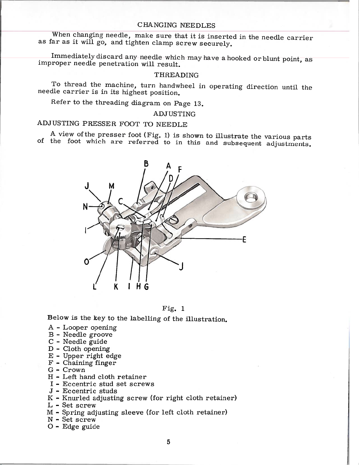
A
view
of
the
needle
to
foot
the
is
the
PRESSER
of
the
which
JM/
N
discard
penetration
machine,
in
its
threading
presser
are
any
highest
FOOT
foot
referred
C
needle
will
tu
diagram
TO
(Fig,
B
which
result,
Til
READING
en
handwheel
position,
on
ADJUSTING
NEEDLE
1)
to
Page
is
in
may
13.
shown
this
have
in
to
and
a
hooked
operating
illustrate
subsequent
or
blunt point,
direction
the
until
various
adjustments.
as
the
parts
Below
-
A
-
B
-
C
D
-
-
E
-
F
-
G
-
H
-
I
-
J
-
K
L
-
M
-
-
N
-
0
the
is
Looper
Needle
Needle
Cloth
Upper
Chaining
Crown
hand
Left
Eccentric
Eccentric
Knurled
Set
screw
Spring
Set
screw
Edge
L
key
opening
groove
guide
opening
right
finger
adjusting
adjusting
guide
cloth
stud
studs
to
edge
K
the
retainer
set
sleeve
I
HG
labelling
screws
screw
(for
(for
Fig.
of
right
left
1
the
illustration,
cloth
cloth
retainer)
retainer)
5
Page 6
AiZLJ
u;’ircc;
the
size
clamp
proper
rn-a
I
‘IWI,
(i
a
rt
securety
and
needle
new
o[
tighten
(Continued)
and
type
screw,
as
far
as
will
go
it
needle
the
in
in
a
2
maxim
i9w
7,.
((‘nh’
he
iieedie
Loosen
screws
sufficiently
lower
to
tighten
manner
screw
left
tin’
l,in’
oh
groove
(B),
the
right
to
iiandwhiee
looper
of
uni
(13)
Fig.
screws
and
hold
to
foot
screw
obtain
securely,
(B)
(JO
,
On
2
manually
to
the
i.
opening
5
inch
the
C
(C)
foot
secure
(B)
proper
iii
operating
clearance
ie[t
B
that
so
up,
the
securely,
(A)inthe
of
side
Continue
the
of
guide
needle
the
slightly
wheel
side
should
needle
the
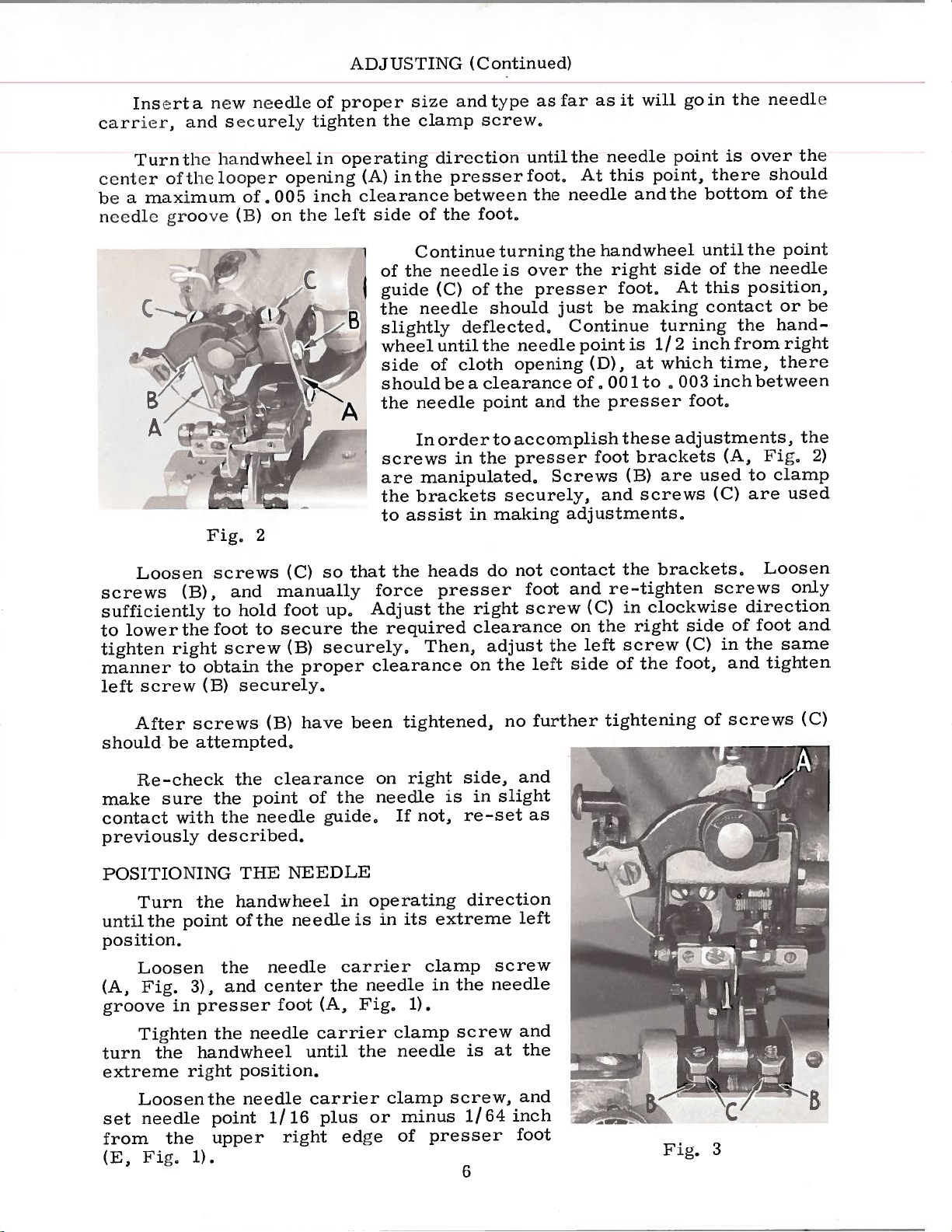
In
screws
manipulated,
are
brackets
the
assist
to
the
force
Adjust
required
clearance
direction
presser
between
the
needle
(C)
until
of
be
order
in
heads
presser
the
Then,
foot,
turning
is
the
of
should
deflected,
the
cloth
a
clearance
point
to
the
securely,
making
in
do
right
clearance
adjust
on
the
the
until
foot,
needle
the
the
over
presser
just
Continue
needle
opening
the
and
accomplish
presser
Screws
adjustments,
contact
not
and
foot
screw
on
the
side
left
At
handwheel
the
be
point
(D),
of,
foot
and
(C)
the
left
needle
point,
this
and
right
foot,
making
is
1/
at
to
001
presser
these
brackets
(B)
screws
the
re-tighten
in
clockwise
right
screw
the
of
poit
the
bottom
until
side
this
At
contact
turning
inch
2
which
,
003
foot,
adjustments,
used
are
brackets,
side
(C)
foot,
is
it
the
the
of
time,
inch
(A,
(C)
screws
of
in
and
over
reshonid
the
position,
the
from
between
Fig,
to
are
Loosen
direction
foot and
the
tighten
of
point
needle
or
hand—
right
there
clamp
used
only
same
the
the
be
the
2)
After
should
make
contact
be
Re-check
sure
with
previously
POSITIONING
Turn
point
the
until
position.
Loosen
Fig.
(A,
groove
turn
extreme
in
Tighten
the
right
Loosenthe
needle
set
from
(E,
the
Fig,
screws
attempted,
the
the
the
described.
THE
handwheel
the
of
the
and
3),
presser
the
handwheel
position.
point
upper
1).
(B)
point
needle
the
needle
center
needle
needle
1/16
have
clearance
of
NEEDLE
needle
foot
(A,
carrier
until
carrier
plus
right
the
guide,
in
carrier
the
edge
been
on
needle
operating
in
is
needle
Fig,
the
or
tightened,
right
not,
If
its
1).
clamp
needle
clamp
minus
of
is
extreme
clamp
in
screw,
presser
side,
in
re-set
direction
the
screw
is
1/64
6
no
and
slight
left
screw
needle
and
at
and
inch
foot
further
as
the
tightening
Fig,
of
3
screws
(C)
B
Page 7
rIj.l
wlieet
position,
even
with
presser
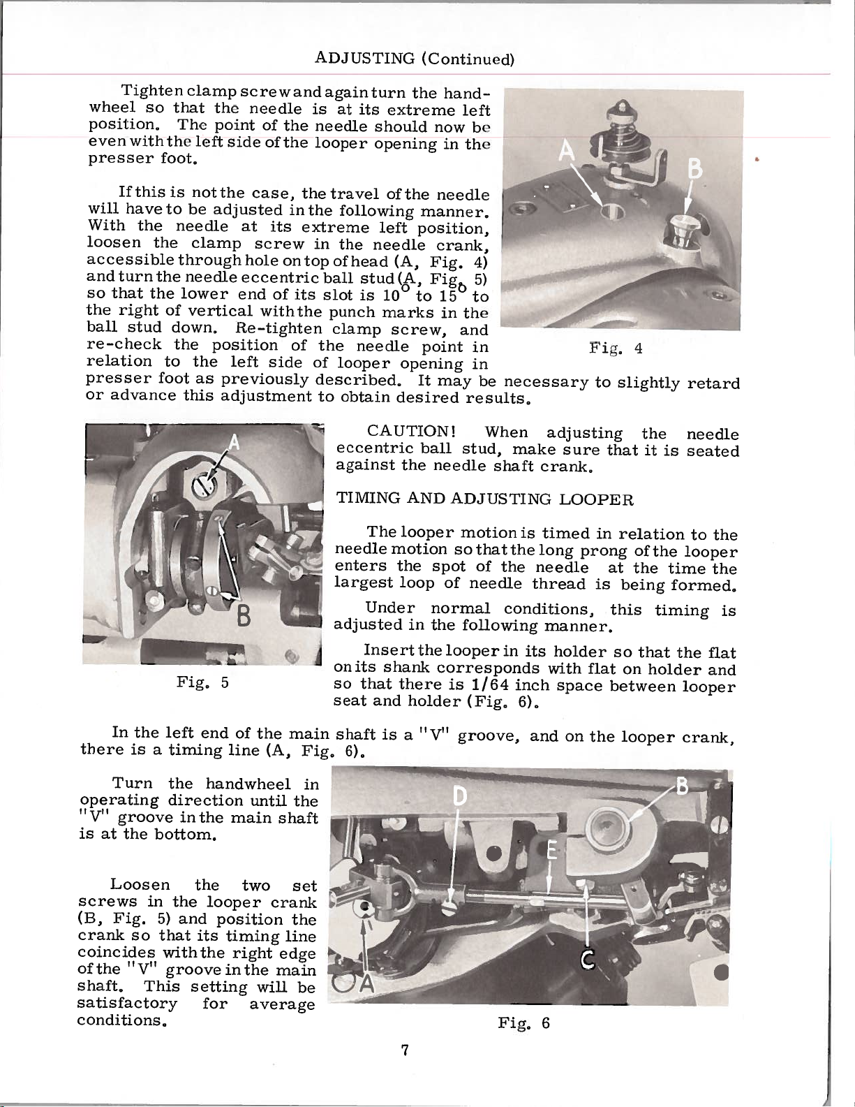
If
will
have
With
loosen
accessible
and
turn
so
that
the
right
ball
stud
re—check
relation
presser
or
advance
SO
this
the
the
the
ten
the
foot,
to
the
of
to
foot
clamp
that
The
is
not
be
needle
clamp
through
needle
lower
vertical
down,
the
the
this
the
point
left
the
adjusted
position
as
previously
adjustment
screw
needle
of
side
of
case,
at
screw
hole
eccentric
end
withthe
Re-tighten
left
side
its
of
ADJUSTING
and
is
the
needle
the
looper
the
in
the
extreme
in
on
top
its
of
the
of
described,
to
again
at
travel
following
the
of
head
ball
slot
punch
clamp
looper
obtain
turn
its
should
opening
left
needle
stud
is
10
marks
needle
the
extreme
of
the
manner,
position,
(A,
(,
to
screw,
opening
It
desired
(Continued)
hand
left
now
in
the
needle
crank,
Eig.
Fig
15
the
in
and
point
may
results,
—
he
4)
5)
to
in
in
be
necessary
Fig,
to
4
slightly
retard
In
there
Turn
operating
“
V’
T
groove
is
the
at
the
is
Ic’c’\
Fig,
left
a
timing
the
direction
inthe
bottom,
5
end
of
line
handwheel
until
main
the
(A,
..J
(.
main
the
shaft
Fig,
in
eccentric
against
TIMING
needle
enters
largest
adjusted
4
on
so
seat
shaft
CAUTION!
The
Under
Insert
its
that
and
is
6),
the
AND
looper
motion
the
loop
shank
there
a
ball
needle
spot
normal
in
the
the
corresponds
holder
“Vu
When
stud,
shaft
ADJUSTING
motionis
sothatthe
of
the
of
needle
conditions,
following
looper
is
groove,
in
1/64
(Fig,
make
thread
its
inch
6),
and
adjusting
sure
crank,
LOOPER
timed
long
needle
manner,
holder
with
space
on
in
prong
is
flat
the
that
relation
of
at
the
being
this
so
that
on
between
looper
the
it
the
timing
holder
needle
is
seated
to
looper
time
formed,
the
looper
crank,
the
the
is
flat
and
Loosen
screws
Fig.
(B,
crank
coincides
of
shaft,
satisfactory
conditions,
the
so
“V’
in
This
the
and
5)
that
withthe
groove
the
looper
position
its
setting
for
two
timing
right
inthe
average
will
set
crank
the
line
edge
main
be
Fig,
7
6
Page 8
A1)JIJSTING
(Continued)
however,
tl
sI
igh
Again,
loope
should
Ic
clear
inc
i’
of
ft
the
h.
On
should
needle,
between
The
adjusting
The
also
provides
adjustment
sleeve
The
greater
a
ad
over
is
just
inne
the
chaining
continuing
clear
on
the
adjustment
sleeve
looper
in
or
looper
extent
variallons
vance
the
turn
the
clear
r
end
the
its
return
prongs,
adjusting
a
secured
is
out,
holder
or
retard
handwheel
spot
the
of
finger
the
right
of
and
the
limited
Vertical
than
in
materials
thi.s
in
the
spot
needle
the
of
rotation
side
stroke,
the
looper
sleeve
amount
loosening
by
orheight
connecting
adjusting
the
in
needle,
in
the
the
of
of
looper
and
timing
operating
needle
eye,
presser
the
the
looper
should
holder
(B,
of
the
adjustment
rod
threads
to
At
this
and
haridwheel,
enter
secured
is
connecting
Fig,
vertical
clamp
also
sleeve,
obtain
cli
and
the
foot
opening
6)
adjusts
used
the
rection
point,
from
be
short
(F,
the
by
positions
or
screw
secured
is
may
des
until
long
the
1/
prong
Fig.
the
crotch
1)
short
in
the
manipulation
rod,
the
height
and
(C)
the
looper
make
ireci
results,
the
pron
16
to
of
no
by
prong
presser
of
the
looper
adjustment,
moving
turning
by
necessary
it
long
of
3732
looper
the
more
of
foot,
looper
of
laterally,
the
vertically,
prong
the
inch
than
the
the
the
of
looper
to
should
1/32
looper
and
midway
looper
Lateral
adjusting
sleeve,
but
to
the
the
the
and
to
If
loosening
by
turningthe
slight
a
adjusting
the
and
rod
Each
that
the
material
There
when
a
the
loop
the
amount
adjusting
will
looper
connecting
Fig.
platen
tensions
and
cause
must
needle
not
is
clamp
the
of
height
sleeve,
sleeve,
7
is controlled
on
be
enough
makes
be
radically
screw
rod
adjustment
Final setting
A
I
platens
the
work
the
its
formed
out
of
in
rollingthe
(E),
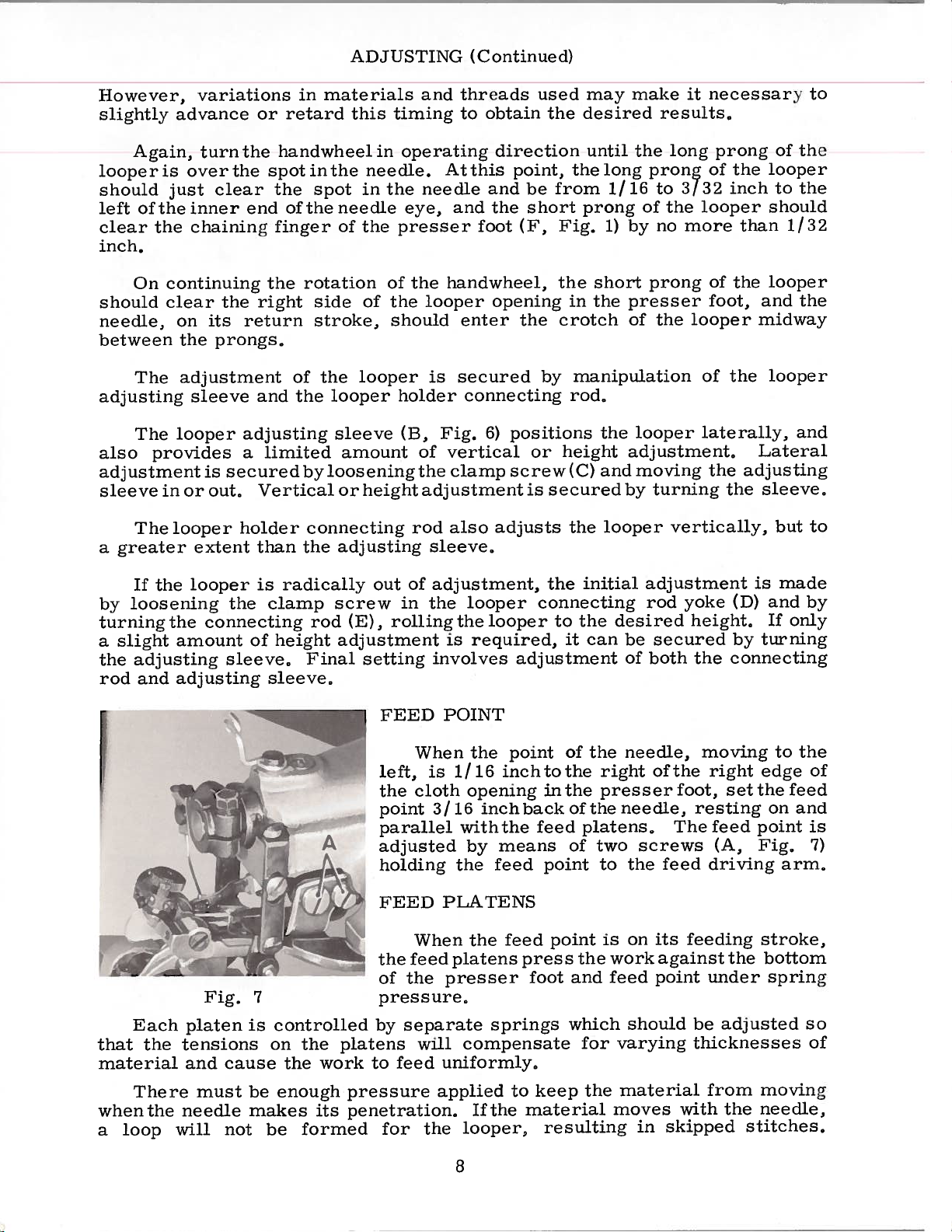
FEED
left,
the
point
parallel
adjusted
holding
FEED
the
feed
the
of
pressure,
separate
by
feed
to
pressure
penetration,
for
adjustment,
the
is
involves
POINT
When
is
1/16
cloth
3/16
the
PLATENS
When
platens
presser
will
uniformly,
applied
the
looper
looper
required,
adjustment
the
point
inchtothe
opening
inchback
the
with
means
by
feed
feed
the
press
springs
compensate
to
If
the
looper,
the
connecting
to
it
of
inthe
of
feed
of
point
point
foot
which
keep
material
resulting
initial
the
can
the
right
presser
the
platens,
two
to
the
and
for
the
desired
be
of
needle,
needle,
the
on
is
work
feed
should
varying
material
moves
adjustment
rod
yoke
secured
both
of
the
foot,
The
screws
feed
feeding
its
against
point
with
skipped
in
(D)
height,
by
connecting
the
moving
right
setthe
resting
feed
(A,
driving
the
under
adjusted
be
thicknesses
from
the
stitches,
made
is
and
If
turning
to
edge
on
point
Fig,
arm,
stroke,
bottom
spring
moving
needle,
by
only
the
of
feed
and
is
7)
so
of
8
Page 9
A
I)J
LISTING
(Continued)
Cht’ck
penetvatt’s
P
the
tWo
‘I’urn[Iig
coititer
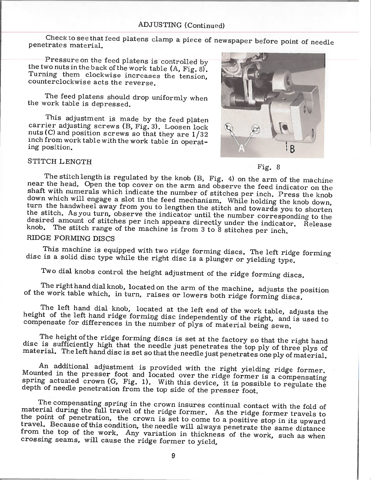
The
the
work
This
carrier
nuts
(C)
inch
from
ing
position.
STITCH
The
near
the
shaft
down
turn
the
the
stitch.
desired
knob.
RIDGE
iessu
nuts
theni
clockwise
feed
table
adjustment
adjusting
and
\verk
LENGTH
stitch
head.
with
numerals
which
handwheel
amount
The
FORMING
to
see
materiaL
I(
on
tii
the
platens
is
posjtion
table
length
will
As
you
stitch
that
the
)aek
ctock\V
acts
depressed.
screws
Open
engage
turn,
of
stitches
range
DISCS
teed
feed
should
screws
with
is
the
which
away
p
platens
ol
the
ise
the
is
made
(13,
the
regulated
top
a
slot
from
observe
of
atens
work
increases
reverse.
drop
Fig,
so
work
cover
indicate
in
you
per
the
machine
ctanip
is
tti)
uniformly
by
3).
that
table
by
the
the
inch
cotitrottud
te
the
the
feed
Loosen
they
the
on
the
the
feed
to
lengthen
indicator
appears
a
pce
(A,
Pig.
tension,
platen
are
in
operat
knob
arm
number
mechanism.
from
is
by
ii).
vhen
lock
1/32
(13,
and
of
the
until
directly
3
of
newspaper
Fig.
observe
stitches
stitch
the
to
under
8
stitches
4)
on
per
While
and
number
before
r
Fig.
the
the
feed
inch.
holding
towards
corresponding
the
indicator.
per
‘1
arm
point
8
of
indicator
Press
the
you
inch.
the
knob
o[
machine
the
to
Release
necdte
on
knob
down,
shorten
to
the
the
This
disc
is
Two
The
of
the
The
height
compensate
The
disc
is
material.
An
Mounted
spring
depth
The
material
the
point
travel.
from
the
crossing
machine
a
solid
dial
right
work
left
of
the
height
sufficiently
The
additional
in
actuated
of
needle
compensating
during
of
Because
top
seams,
disc
knobs
hand
table
which,
hand
left
hand
for
differences
of
the
left
hand
the
presser
crown
penetration
the
penetration,
of
this
of
the
will
is
equipped
type
control
dial
knob,
dial
knob,
ridge
ridge
high
disc
adjustment
(G,
spring
full
travel
condition,
work.
cause
while
in
forming
that
foot
from
the
the
located
turn,
forming
in
is
set
Fig.
in
Any
the
with
the
height
located
the
the
is
and
1).
the
the
of
the
crown
the
variation
ridge
two
right
on
raises
number
discs
needle
so
that
provided
located
top
crown
needle
ridge
disc
adjustment
the
or
at
disc
the
With
side
ridge
is
set
former
forming
is
a
arm
of
lowers
the
left
independently
of
plys
is
set
at
just
penetrates
needle
with
over
this
device,
of
the
the
insures
former.
to
come
will
always
in
thickness
to
yield.
plunger
of
the
the
both
end
of
material
the
just
the
ridge
presser
continual
As
to
discs.
or
ridge
machine,
ridge
of
the
of
the
factory
the
penetrates
right
yielding
former
it
is
possible
the
ridge
a
positive
penetrate
of
the
The
yielding
forming
forming
work
right,
being
so
top
foot.
contact
work,
left
adjusts
table,
that
ply
one
is
former
stop
the
ridge
type,
discs.
the
discs.
adjusts
and
is
sewn.
the
right
of
three
ply
of
material.
ridge
a
compensating
to
regulate
with
the
travels
in
its
same
such
forming
position
used
hand
plys
former.
fold
upward
distance
as
when
the
to
of
the
of
to
9
Page 10

A
I).)
LS1:ING
(Coititued)
plunger
there
the
of
yond
Fig.
of
it
the
is
with
inch
the
become
dial
shaft.
the
Pressure
rod
3/32
is
head
Should
the
limits
1.
Rotate
Remove
2.
Liftthedialknohsothatits
3.
in
dial
over
Replace
4.
9
directly
the
clearance
plunger
the
of
right
screw
seat,
stationary
screw
upper
necessary
right
hand
Rotate
applied
shaft.
(A,
but
and
nut.
between
hand
dial,
Fig.
so
the
stop
spring.
\Vhen
the
ol
comparabte
ime
and
work.
right
the
made
tocated
ridge
desired
To
needle,
For
less
To
turn
clockwise,
the
to
Generally
increase
to
dial
in
and
9)
stop
that
its
in
dial
pin
by
the
the
range,
the
the
and
right
By
using
in
adjust
turn
increase
yielding
key
making
rL(lge
the
to
crew
the
using
former
depth.
knurled
the
crown
the
the
time
peneti’ation,
screw
in
counterclockwise
the
of
or
the
decrease
top
iiroceed
required
spring
pin
(B).
disengages
remains
slot
required
dial
the
preliminary
the
fluinei,
weight
so
n
right—hand
the
height
All
of
crown
adjusting
the
the
ridge
correct
plunger
direction,
direction
reengages.
that
so
further
beach
the
for
turn
spring
center
forming
follows:
as
from
insert
material
of
it
that
crown
pros
more
screw
the
pressure
for
pressure
holder
height
the
to
the
engaged
until
penetration
fetched
does
the
not
dial
needle
adjustments
adjusting
foot.
ser
penetration
counterclockwise.
screw
adjusting
the
of
less
by
disc
is
and
of
end
the
stationary
with
stop
its
material.
hemmed
he
to
contact
knob,
penetrates
should
clockwise.
the
on
pressure.
adjusting
obtained
the
underside
discs
the
of
its
key
the
pin
setting
set
screw
of
crown,
screw
travel.
stop
in
passes
the
the
he
the
the
when
be
pin
the
Refinements
push
rod
To
height
limits
the
simply
located
ted
stud
in
dial
tighten
Lateral
forming
moving
The
discs
distant
opening
adjustment
hexagonal
two
inthe
base
correct
increase
the
of
of
loosen
in
the
located
the
screws.
discs
the
from
in
position.
stop
left-hand
the
the
dial
desired
adjustment
work
should
the
the
made
is
and
this
of
screw
or
left-hand
two
and
the
in
accomplished
is
table
be
sides
presser
by
screws
sliding
adjustment,
(A,
decrease
disc
dial
locking
turn
center
direction.
of
right
spaced
of
foot.
loosening
(B,
work
Fig.
the
the
the
Fig.
table
10).
beyond
range,
screws
slot
of
Re-
ridge
left.
or
equi
cloth
This
the
the
the
10)
by
to
within
any
range,
may
Fig.
be
made
10
by
adjusting
the
Page 11

1)1
A
\V()
iii
tah[e
control.s
depentty
the
Fig.
[ISTIN(
I
I
TIi
the
by
The
under
8).
(Continued)
TA
e
pos
woi.k
the
large
the
tension
controlLed
side
I
Lt
tabto.
tension
ion
TENSIC)N
of
tI’er
TJie
coil
spring
on
on
the
by
of
the
the
left
a
left
idge
tension
right
ridge
small
in
end
for
the
ridge
coil
of
ni
Lug
appli
base
forming
spring
the
discs
ccl
of
the
forming
work
to
disc
located
table
is
the
nachiie
is
iixc(
work
disc.
in—
in
(H,
disc
tension,
counterclockwise
Thread
(1)
(2)
Move
(3)
edge
edge
Adjust
not
in
of
guide
penetrate
the
adjust
(4)
Adjust
located
as
close
firmly
If
the
material
skipped
g.
adjust
machine
knee
the
needle
required
left
cloth
in
to
hold
stitches
press
material
on
the
hand
retainer
the
the
the
screw
acts
the
in
accordance
to
the
front
penetration.
folded
direction.
dial
cloth
needle
work
is
carried
and
1
(B,
reverse.
STARTING
right
directly
of
edge
knob
and
opening
as
possible
on
the
improper
fension
creased,
sewn,
by
For
11).
Ttirning
counterclockwise
Fig.
8).
with
and
insert
over
the
presser
Sew
a
at
the
Check
in
the
same
crown.
of
The
the
and
discs
along
while
with
needle
on
depending
the
following
right
Turning
TO
OPERATE
threading
work
the
right
foot.
few
stitches
desired
penetration
manner.
cloth
presser
set
the
the
needle,
penetration.
both
hand
nut
screw
under
ridge
depth,
retainer
foot,
relative
needle
discs
on
disc
clockwise
acts
diagram,
feed
and
at
no
can
the
weight
adjustments:
tension,
the
reverse.
clockwise
pointS
forming
inspect.
turn
the
the
single
and
must
to
the
penetrating
is
loop
at
will
Page
crown
all
ridge
be
increased
of
adjust
increases
increases
13.
with
disc
If
right
piy
times
forming
form,
material
For
the
and
the
hand
of
(G,
the
(A,
nut
tension,
left
tension,
folded
against
needle
dial
fabric
H,
Fig.
be
adjusted
discs
material.
resulting
or
being
hand
edge
does
knob
de—
Fig.
the
and
1),
to
in
Lateral
tric
Adjustment
eccentric
Tension
adjusting
Forming
Tension
sleeve
sition.
tighten
adjustment
adjusting
on
Discs.
on
(M).
Turn
the
studs
in
adjusting
the
screw
left
Loosen
spring
two
line
right
set
(N)
hand
is
(J)
of
studs
hand
and
retainer
set
adjusting
screws.
secured
laterally
feed
(J).
the
screws
is
made
spring
set
by
to
screw
can
(I
sleeve
loosening
desired
by
loosening
actuated
(L).
be
varied
&
N)
(M)
while
to
two
position.
two
crown
Refer
by
holding
secure
11
screws
is
to
turning
(I)
screws
controlled
adjustment
the
adjusting
desired
and
(I)
spring
tension,
moving
and
by
the
under
stud
turning
knurled
adjusting
(J)
and
eccen
the
HRidge
in
po
re
Page 12

STARTING
TO
OPERATE
(Continued)
should
right
of
with
catalog
various
actual
listing
required
indenting
by
4124-27
1213
18-74
1170
back
the
This
edge
parts.
be
Adjust
(5)
and
the
edge
Removing
(6)
withdrawn
work
stitch.
ILLUSTRATIONS
This
views
in
found
pieces
the
in
dicated
44
45
46
47
The
the
this
part
of
their
a
Numbers
position
ordering
Component
It
will
reason
complete
At
book.
number
guide.
he
set
hand
material
the
work.
from
a
diuick
has
sections
position
of
the
in
the
in
the
of
L
L
is
sub-assembly
is
that
parts
noted
that
of
will
known.
part
their
replacement
the
so
ridge
To
the
pull
been
in
parts
particular
first
Always
of
Looper
the
in
book
facilitate
The
edge
the
that
forming
against
remove
material,
ORDERING
of
the
with
column
in
the
sub-assemblies
descriptions
will
work
away
arranged
the
mechanism
machine.
their
illustration.
the
use
Carrier
Clamp
Spot
Screw
above
of
should
be
locating
IDENTIFYING PARTS
guide
folded
disc.
edge
the
push
from
view
are
part
Example:
Screw
Screw
example
these
be
found
edge
after
the
you in
REPAIR
to
simplify
On
parts
being
reference
number
which
under
Ball
parts
ordered.
a
the
(0,
[rig.
of
the
In
operating
guide.
stitching,
knee
order
are
shown
the
page
numbers,
shown.
Reference
can
description
the
Joint
that
the
individually
numerical
illustration
1)
material
press
to
PARTS
ordering
opposite
numbers
listed
be
ball
only
has
the
machine,
that
see
to the
break
so
that
description
only,
number
the
in
furnished
of
and
is
index
and
of
description
is
the
right,
the
repair
the
the
second
the
the
not
all
a
lateral
guided
hold
needle
and
thread
parts.
parts
illustration
and
merely
and
should
column.
for
repairs
main
strap
recommended,
the
parts
adjustment
directly
the
entirely
is
remove
lock
and
Exploded
may
be
will
number
the
indicate
never
subassembly.
are
when
be
are
not
shown
only
over
folded
the
the
seen
be
of
used
in
1
1
1
2
listed.
so
in
the
Where
Part
numbers
Success
UNION
poration,
ing
to
Maximum
Genuine
mark
forwarded
otherwise
is
Prices
SPECIAL
its
most
the
efficiency
your
directed.
the
construction
represent
in
the
subsidiaries
approved
needles
guarantee
are
net
b.
f.
o.
USE
operation
Needles
and
are
cash
shipping
A
the
same
GENUINE
and
and
scientific
durability
packaged
the
of
and
charge
permits,
NEEDLES
of
these
Repair
authorized
highest
subject
point.
is
part,
made
each
regardless
machines
Parts
principles,
assured.
are
labels
with
quality
TERMS
to
Parcel
to
part
AND
as
REPAIR
furnished
distributors.
and
marked
in
material
change
Post
cover
postage
is
of
can
are
without
shipments
12
PARTS
the
by
with
with
are
stamped
catalog
secured
be
They
made
ZnZn...pcciaI®
workmanship.
and
notice.
and
insurance.
in
are
its
which
only
Union
designed
utmost
All
part
they
with
Special
.
This
shipments
insured
number.
appear.
genuine
Cor
accord
precision.
trade
are
unless
Page 13

Page 14

11
14
Page 15

IV[AIN
FRAME,
BUSI-IINGS,
COVERS
A
ND
MISCELLANEOUS
PARTS
Ref.
10
11
12
13
14
15
16
17
18
19
20
21
22
23
24
25
26
27
28
29
30
31
32
33
34
35
36
37
38
39
40
41
42
43
44
45
46
47
48
49
50
51
52
Part
No.
1
2
3
4
5
6
7
8
9
No.
16—39
41-49
LS314
125-23
61-30
18-565
41-42
468—23—1
1160L
468-23
1183
1132
20—60
61-46
18-768
110-401
125-23
16-148
61—32
61—25
426—47
20—79
16-194
LS75
26—47
1081
32—107
18-330
125—23
16—386
18-764
1197
1220
1221
32—36
18-38
155—9
125—23
416—374
1195
CS331
1197
18-768
97—56
18-C94-1
18-664
22-149
18—768
97-51
16—279
32—262
L
L
L
L
L
L
L
8—89
L
Bushing
Thread
Screw
Oil
Cup
Oil
Tub
Scre
Thread
Tension
Nut
Tension
Tension
Tension
Thumb
Tub
Oil
Screw
Model
Oil
Cup
Bushing
Oil
Tub
Oil
Tub
Stitch
Nut
Bushing
Spring
Plunger
Set
Screw
Cover
Screw
Oil
Cup
Main
Plug
Screw
Set
Screw
Spring
Cover
Screw
Indicator
Oil
Cup
Main
SetScrew
Screw
Belt
Guard
Screw
Set
Screw
Name
Screw’
Set
Screw
Taper
Screw
Name
Bushing
Bottom
Guid
Guidc
Staff,
Plat
Adjusting
Plat
Shaft
Screw
Washe
Plat
Shaft
Plate
Pin
Plate
Cover
complel
Staff,
Dis
Spring
Nut
Bushing,
Bushing,
with
Plunger,
left
right
Dc s
hook
cription
complet
Ami,.
Req.
1
1
1
1
1
1
1
1
1
1
2
1
1
1
2
1
1
1
1
1
1
1
1
1
1
1
1
2
1
1
1
1
1
1
1
1
1
1
1
1
1
1
1
6
1
1
3
1
2
1
1
1
15
Page 16

8
6
I
16
32
Page 17

Rn.
10
11
12
13
14
15
16
17
Ill
19
20
21
t22
23
24
25
26
27
28
29
30
31
32
32A
33
34
35
36
37
38
39
40
41
42
43
44
45
46
47
48
49
50
51
52
52A
53
54
55
56
57
58
59
61
62
63
*64
*65
*66
67
*
Component
For
For
Nit.
I
2
3
4
5
6
7
8
9
use
use
I
22559
1192
1025
1031
1005
22653
449-27
4124-27
1213
1170L
4118-15
1170
29BL—lOO/040
4118-24
810
439—7
SB15
1243L
l333L
part
on
machines
on
Style
St
‘I
Ne.
448—135
48—135
16—321
18—737
137—19
666—170
17—149
447—141
666—239
660—204
18-492
40—199
45-351
137—19
33—149
18—674
149—16
79—31
21—213
18—767
23—327
23—338
40-126
18—732
44
6-118
18—751
17—114
17—150
14-432
57-56
39—92
139-10
27-221
18—C97
115-118
18-738
18-71
22-8
L
18-74
70-53
17-146
18-662
L
20—31
36-16
L
30—52
22—9
18-70
14-14
48-105
18-702
of
150-230
1)
L
L
L
L
B—B
No.
447-141,
prior
Looper
Set
Oil
Oil
Stud
Needle
Feed
Oil
Feed
Screw
Stitch
Ball
Spriri
Screw
Feed
Feed
Shakeproof
Screw
Feed
Eccentric
Stud
Main
Handwheel
Collar
Counterweight
Drive
Set
Looper
Set
Looper
Pi
Looper
Sleeve,
Stud
Screw
Looper
Nutfor4ll8—15
Loope
Needle
Needle
Colla
Needle
and
to
improved
PEED,
Driving
Crank
Bushing
Screw
Wick
Wick
Drive
Wick
Oil
Screw,
1,0,?
Ring
Spot
Fiber
Driving
Wick
Driving
Regulator
Point
Point
Driving
Screw
Shaft
Set
Screw
Set
Screw
Spot
Scre’,
Set
Scre
Gea
Scre’,
Carrier
Clamp
Scre’,
Carrier
ClampScrew
Carrier
Clamp
SpotScrew
Screw
for
Carrier
Scre
Carrier,
Screw
NeedleClam
P1
ClampScrei
Set
Screw
Carrier
Needle
Scre’,
Spot
Scre’.
Screw
Ref.
after
machines.
LOOPER
Retainer
for
Screw,
Washer
Retainer
Washe
Lever
Stud
Screw
Screw
looper
Carrier
No.
improved
Crank,
Eccentric
connecting
for
Lever
Eccentric,
Balance
Yoke
Yok
Ball
ball
Shaft
complete
Shaft
Shaft
B
AN!)
eccentric
Link
Block
Joint
joint
Style
N
PVDI
complete
Connection,
rod
.250
inch
adjustment
Crank
150-230
P
I
)Il[VING
I’aei’ipI
complete
throw
machines.
PA
RI’S
A
en
niL
hint.
I
1
2
1
1
4
1
1
1
1
2
1
3
1
1
1
1
1
I
2
‘2
1
1
1
1
1
1
2
1
2
1
1
2
1
1
1
1
1
1
1
1
2
1
1
1
1
1
1
1
1
1
1
1
1
1
1
2
1
1
1
17
Page 18

6
1
43
42
18
Page 19

h’IlliI.)
P1
/\lliS,
I1IDC3Ii
ICt)R\/llNC
AND
DRIVING
PARTS
PcI.
—_No•
HA
jill
:2
3
5
7
3)
10
11
12
13
14
15
16
17
18
19
20
21
±22
23
24
25
t25A
26
27
28
29
1:30
t3OA
t3OB
t30C
t30D
t30E
t30F
:r3l
32
33
±34
t34A
±35
t35A
36
37
38
39
40
41
42
43
44
t46
I
‘a
it
No•
I•’ted
Plate
is-sso
9$3—3h)
11—505
22—326
113—749
20—35
6
24—321
10—910
24—322
39—136
20—129
19—628
21—248
10—579
113—634
140—16
14-503
20—141
18—1065
21—70
79—31
13-500
4149—18
44—328
44—321
69—C19
18-C889
48—69
48—184
18—710
14-506
1284L
1022
L
44-C257
444-322
44-322
21—433
20—122
99-348
heed
‘cod
Shalt
Peed
Screw
Nut
Food
Screw
Food
Spacing
Nut
Scrow
Spring
Screw
Sot
Screw
Ridge
Shaft
Adjusting
Adjusting
Sprbg
Ball
Set
Screw
Regulator,
Ridge
Ridge
Slide
Screw
Ridge
Ridge
Screw
Driving
Collar
Screw
Ridge
Yielding
Yielding
Spring
Nut
Frame
Plate,
Plato,
Block
18—633
1246L
l304L
1306L
14-504
14-521
448-C132
48-182
18—497
17—C141
47-131
39-C13OB
18-C94-2
33-C143
27-C149
18-C215-1
14-C147
1284L
1022
L
Pin
Link
Screw
Shaft,
Shaft,
Ridge
Ridge
Screw
Stud
Connecting
Collar
SetScrew
Eccentric,
Driven
Screw
Shaft
Collar
Set
Forming
Forming
I’latc
‘late
‘late
Cotlar
Forming
Nut
Screw
Forming
Forming
Forming
Forming
Shaft,
Forming
Ridge
Set
for
right
for
right
Gear
Screw
IIiildtij’
Iluldei’,
IIulcIoi’,
Iloldcr
left
right
for
Ridge
Screw
Rod
.
240
Disc
adjusting
Disc,
Disc,
Disc
Disc
left
for
Disc,
Forming
ridge
ridge
Disc
Disc
inch
I
)usci:iptain
—
tuft
ii,
lit
lIinic
Cradle
left
left
Crank
Crank
ridge
right
Forming
forming
forming
Crank
Crank
throw
Pin
left
ridge
forming
Assembly,
Plunger
forming
disc
assembly
disc
disc
right
And.
I3eij.
2
1
1
1
2
2
1
2
1
1
2
2
2
1
1
1
1
1
1
1
1
2
1
1
1
1
1
2or3
1
3
1
2
1
1
1
1
1
2
1
1
1
1
2
1
1
1
1
1
1
1
2
2
1
1
3
1
2
1
For
For
t
use
use
on
on
machines
Style
150-230
prior
to
and
improved
after
machines.
improved
Style
150-230
19
machines.
Page 20

17
50
20
Page 21

\‘OIl.
APHON
A
NI)
SliI’Cl[
DIPI’IL
INCtFLA’I’OH
PARTS
Ref.
10
11
12
1
14
15
16
17
18
10
20
21
22
23
24
25
26
27
28
20
30
31
32
33
34
35
36
37
38
39
40
41
42
43
44
45
46
47
48
49
50
51
52
53
54
55
No.
5
(5
7
U
3
I
No.
028
1
8—
1
21-40
itt—:o
.11
149—30
21—237
70—31
22—C2l4—4
8-ClOO
1
1H—100’1
22-296
4107—58
18-768
110—
22-C21
22—316
115-Cl
45-Cl50
22-Cl
22—C214—1
2l-C54
47l-C544
71—Cl
22-C2l4-4
7l—Cl33
14-96
1
32—296
61—49
18-960
6258
1025
18-330
32—291
183—36
16-394
16—397
20—34
18—564
1
18-129
18—126
70—28
18-493
21—C153
1388
1025
14-507
1003 L
45-203
40-C213-2
22—C137
71—107
131—C163—1
18-C884
20—C117
:
:32
8-C944
L
8—C94—1
L
L
4-4
13
51—1
B
34
Screw
Siiich
Screw
Ad1tistjn1r
SqLlare
Stitch
Stitch
Stitch
hinge
Pu
Work
Knuckle
Work
Screw
Snap
Oil
Set
Spring
Set
Scre
Cover
Work
Nut
Stitch
Knuckle
Work
Work
Knee
Stitch
Collar
Knee
Set
Screw
Knee
Washe
Cotter
Stitch
“S’
Work
Nut
I
)epi.Ii
Plunger
Spring
13u11
Pu—
I[ead
Depth
Screw
Regulator
Pin
P11
Depth
Depth
Pu
Table
Assembly
Spring
Pin
Spring
Table Pivot
Cover
Tub
Screw
Screw
Apron
Ridge
Ridge
Depth
Assembly
Table
Table
Press
Screw
Depth
Set
Screw
Lift
Shaft
Lift
Lever
Pin
Depth
hook
Table
Regulator
Regulator
Scre
Pu—
Regulator
Regulator
Regulator
Tension
Tension
Tension
Forming
Forming
Regulator
Pivot
Pivot
Rod
Regulator
Regulator
Tension
Plate
Sleev
Spring
Shani
Knuckl
Shaft
Shaft
Shaft
Set
Shaft
Shaft
Adjusting
I)vsc
I\
not)
1lange,
Block
Leve
Bushing,
Shaft
Scre
Lock
Bearing
Shaft
Shaft
iipton
Assen-ibly
Bushing,
Stop
Screw
Spring
complet
Scre
Scre’
Screw
left
right
An-it
Req.
1
1
1
1
1
1
1
2
1
1
1
2
1
1
1
1
1
1
1
1
1
1
1
1
1
2
1
1
1
1
2
2
1
1
1
1
1
1
1
1
1
1
4
1
1
1
1
2
1
1
1
1
1
1
1
21
Page 22

£17
Page 23

lIiHSSKH
POOl’,
\\OHF.
Sll’I’OHT
(‘I
Al
P
ANt)
A(’(’lNSO(l[ES
*
(((‘I:.
No.
±5
10
11
12
13
14
15
16
17
18
19
20
21
22
23
24
25
26
27
28
29
30
31
32
33
34
35
36
37
38
39
40
41
42
43
44
45
46
47
48
49
I
‘a
it
No.
1
2
3
4
6
7
8
0
10—307
(‘5327
50—160
1(76
405—572—2
405—576—3
17—87
18—634
21—300
21—62
22—317
13—1074
21—240
137—77
126—54
126—57
1733
13—261
5—576
5—532
17—111
LS330
75—251
1351
lO8lL
16—214
18—416
18—643
6—56
122—C38
18—292
4-141
18—533
50—211
18—939
CS320—1/2
854L
14—256
54484
71—87
660—168
4129—18
129—18
22508
144—27
413
1405L
21201
652—16
18—955
110—323
18—768
144—28
403-11
5C303
Srr’w
I
Iliarket
Screw
I’i’rssei’
((5
hoot,
loot,
sri’
I’leeeotnic
Screw
Set
Spring,
S3ing,
Pin
IkinniecI
Spring
(or
for
Aclusting
Retainer
Crown,
L
L
(‘town,
Spiint
Screw
Presser
Presser
Stud
Set
Edge
Screw
for
Cur
loot,
Screw
Guide
Screw
I3usIiin,
spring
SetScrew
Screw
Needle
Chaining
Guide
hAnger
Screw
Work
Set
iN
Screw
Bracket
Support
Plate
Screw
Set
Screw
Screw
Stud
C
Stud
Knee
Knee
Knee
Press
Press
Press
Knee
Rod
Plate
Pad,
Press
Screw
PeltPad
Oil
Can
Open
End
Screw
Wrench
Driver
Washe
Stove
Regulator
Eolt,
for
Plate
Screw
Work
Thread
Wood
Apron
Screw,
Insolator
Stand
for
roioptete
compLete
Html
No.
No.
No.
No.
‘out,
Cushion
complete
Pad
holding
thread
l)rsri’iptioo
405-576-2
405—576—3
Screw
405—576—2
405—576—3
main
section,
main
section,
tensioning
machine
stand
No.
for
for
to
table
No.
405—576—2
405—576—3
‘1
llrq.
1
4
4
1
2
1
1
1
mt.
2
4
2
1
1
1
1
1
1
1
1
1
1
1
1
1
1
2
1
1
1
1
1
1
1
1
1
1
1
1
1
1
1
1
2
2
2
1
1
1
1
1
1
1
1
1
1
*
Furnished
For
For
t
use
use
on
on
with
machines
Style
machine
150-230
prior
not
hut
to
improved
and
shown
after
on
improved
machines.
picture
plate.
Style
150-230
23
machines.
Page 24

B
I;HIC
NV
I
I
‘art
No.
Page
No.
‘sit
No.
AL
Page
No.
INDEX
OF
Part
No.
A Il
1’S
P
I
‘aie
No.
I’az
No.
Page
No.
4-141
5—502
6—56
8—09
14-14
11—96
11-ElI?
11—256
11—432
14—503
14-504
14—
505
14—506
14—307
14—521
SKiS
16—39
16—149
16—194
16—214
16279
16—321
16—386
16—394
16—397
17—87
17—111
17—114
17—C141
17—146
17-149
17-150
18—38
18—70
18—71
18—74
18—C94—1
18-C94—2
18—C97
18—C100
18—126
18—129
18—C215—i.
18—261
18—292
18—307 23
18—330
18—416
18—492
18-493
18—497
500
1818—533
18—564
18—565
18—579 19
18—628
18—633
18—
634
18—643
18—662
18—664
18—674
18—702
18—710
732
18—
.3
23
3
23
15
17
1
19
17
19
10
19
19
21
17
is
15
15
23
1;)
17
15
21
21
23
23
17
19
17
17
17
15
17
17
17
15,21
19
17
21
21
21
. .
.19
23
23
21
15,
23
17
21
19
19
23
21
15
19
19
23
19,
23
17
15
17
17
19
17
737
10—
11—733
10-749
19—751
18—764
18—767
18—768
18—COOl
18—0189
18—918
18—939
18—C944
18—955
18—960
18—1028
18—1064
18—1065
18—1074
20—31
20—34
20—35
20-60
20—79
20—C117
20-122
20-129
20-141
21—C54
B
21—62
21—70
21—C153
21—213
21—
237
21—240
21—248
21—300
21-404
21—433
22—8
22—9
22—C137
22—149
22—C151—1
22—C214-1
22-C214—4
22—296
22—316
22—317
22—326
23—327
23—338
24—321
24—322
26—47
27-C149
27—221
29BL—100/040
30—52
32—36
32-107
32—262
32—291
32—296
33—C143
33—149
36—16
39—92
...
17
17
19
17
15
17
15,21,
23
21
19
19
23
21
23
21
21
21
19
23
17
21
19
15
15
21
19
19
19
21
23
19
21
17
21
23
19
23
21
19
17
17
21
15
21
21
21
21
21
23
19
17
17
19
19
15
19
17
.17
17
15
15
15
21
21
19
17
17
17
39—C130
39—136
40—126
40-199
40—C213-2
41—42
41—49
44-C257
44-321
44-322
44—328
45—C150
45-203
45—351
47—131
48-69
48-105
48—135
48—182
48-184
50-160
50-211
57—56
61—25
61—30
61—32
61—46
61—49
69—C19
70-28
70-53
71—87
71—107
71—C133
71—C134
75—251
LS75
79—31
97—51
97—56
99—342
99-348
99-349
99—350
110—323
110—401
115—C113
115—118
122—C38
125—23
126—54
126—57
129—18
131—C163—1
137—19
137—77
139—10
140-16
144—27
144-28
149—16
149—30
155—9
183—36
II
A
,.19
,,19
.17
.17
.21
.15
.15
.19
.19
.19
.19
.21
.21
.17
.19
.19
.17
23
23
21
15
21
17
19
19
23
23
17
is
15
15
15
21
19
21
17
23
21
21
21
23
15
17,
21
15
15
19
19
19
19
21,
15
21
17
23
15
23
23
23
21
17
23
17
19
17
19,
23
SC303
24314
1
CS320—1/2
CS327
124330
CS331
403—li
405—576—2
405—576—3
413
416—374
426—47
439—7
444
—322
446—118
447—141
448—Cl
448—135
449—27
468—23
468—23—1
471-C544
652—16
660—168
660—204
666-170
666—239
810L
854L
876L
1003L
1005L
1022L
L
1025
1031L
1081
L
1132
L
1160L
1170L
1183L
1192
L
1195L
1197
L
1213L
1220L
1221
L
1243L
1246L
1284L
1304L
1306L
1333L
1351
L
1388L
1405L
1733L
4107—58
4118—15
4118—24
4124—27
4129—18
4149—18
4149—30
6258
21201
22508
B
22559
22653
B—8
C
54484
23
15
23
23
3
15
23
23
23
23
15
15
17
19
i7
17
32
19
17
17
15
15
21
23
23
17
17
17
17
23
23
21
17
19
17,21
17
15,23
15
15
17
15
17
15
15
17
15
15
17
19
19
19
19
17
23
21
23
23
21
17
17
17
23
19
21
21
23
23
17
17
23
24
Page 25

Here
are
Oil
for
Specifications
Union
Sewing
Specification
roleum
mended
machines.
roleum
white
1.
For
mount.
roleum
high
mitters.
3.
Where
used.
UNION
SPECIFICATION
Viscosity
Flash
Pour
Color
Neutralization
Viscosity
(D&D
Compounding
Copper
*Anline
*Used
viscosity
oil,
for
Specification
oil,
viscosity
withamaximum
or
use
where
Specification
viscosity
oil,
Specification
quality
grease
is
similar
It
3
No.
SPECIAL
S.S.U. at
(Mm.)
(Max.)
A.S.T.M.
Index
Mm.)
Corrosion
No.
with
Buna
oiling
all
freedom
300
for
to
greaseisnot
100°F
(Max.)
(Max.)
No.
(Max.)
N
Rubber
Special
Machines
quality
a
174
specifies
100
seconds
applications
175
specifies
100
seconds
A.S.T.M.
specifies
87
seconds at
specifies
100
use
commercial
NO.
“0”
from
in
obtainable,
90-125 90-125
0.10
None
175-225 175-225
high
at
100°F.
on
high
a
at
color
stainingispara
oil
a
high
100°F.
general
a
ball
bearings
N.L.G.l.,
174
350 350
20 20
3
0.10
85 85 85
1A
Retainers
Recom
high
quality
100°F.,
number
quality
purpose
and
grease
No.2may
175
300-350
1
None None
1A 1A
speed
water
trans
87
350
20
0.10
175-225
pet
pet
pet
of
No.
3
NOTE
meeting
essential.
be
These
and
separate.
NOTE
shall
not
fINEST
1:
above
These
Oxidation
1.
2.
Rust
3.
Lubricity
4.
Anti-oxidants
Film
5.
additives
removable
2:
Oils
be
not
Extreme
1.
2.
Tackiness
Lead
3.
4.
Detergents
/
QUALITY
Ihe
used
of
use
inhibitors
strength
containing
soap
non-corrosive
classification
may
include:
inhibitors
additives
additives
must
be
by
at
any
pressure
or
adhesive
additives
UNION
completely
wick
the
following
time:
additives—corrosive
SPECIAL
CORPORATION
additives
is
desirable
solubleinthe
feeding nor
additives
type
in
but
shall
additives
oils
not
oil
they
Page 26

Union
Special
Wants
to
Helpibu
union
Sp(’(idl
educe
your
system
to
parts
and
a
Machine
Repami—pionuo’
nip
(lnion
I
arid
niaimntenuancedoHars
your
Special
econ
d
keeping
first
The
Form
237)
equnr
ed,
theircostare
-
--
second
The
on
Request
233).
out
fills
repair
the
in
Card”
When
top
the
costsisdesired.
Cut
I’
sev.’ing
spot
lii’tp
i
iventony
Maintenance
nuictiunes
siI(ItI(’sts
system
system
for
each
the
car
dispulled
entered
I
system
(Form
machine
a
of
a
“Repair
time
the
Sewing
Olti’iiii(
1
utilizes
repair
niachinie
mactunis
system
Records
two
using
sewing
ri
normally
is
Two
234),
requires
Request
work
two
iiiainitoinannco
ieqouu
to
iiiexpeiieinced
Or
VilFiatiOliS
Machine
a
machine
troni
the
and
is
practical
speed
1
short
o:ards
the
spaces
ii
used
record
a
“Machine
service,
Card
started,
systi’Iiis
ahuron
mug
routine
order.
of
a
provided
Maintenance
in
a
File
arid
provided
when
cards
the
and
the
Machine
to
piiipoint
a
nally
repairs.
competent
lo
help
Union
by
When
repair
and
detailed
used:
Repair
it
parts
used
111.11)
record
keepiing
uimainuteumance,
high
opematons
spot
these
maintenance
Special.
Record
a
i
epair
date,
the
card
information
a
“Repair
Record”
Foreman
or
to
mechanic.
a
and
costs:
simple
plant.
the
more
are
forelady
gives
card
parts
is
--
(Form
their
nid
cm
problems,
is
used,
retiled.
tills
He
cost,
Maintenance
conipletion
and
eat
the
‘Machine
Wtiichevei
reduce
to
Repair
While
abnormally
caused
recommends
system
Excessive
eliminated
be
needed
for
spare
downtime
when
the
For
free
inventory
local
Union
Repair
needless
Part
record
by
For
parts.
parts.
overall
lists
routine
is
sample
tune.
Record
systemisused,
maintenance
Inventories
keeping
high
maintenance,
repairs.
that
manufacturers
each
typeofsewing
machine
withanorderly
is
There
Long
kept
a
to
savings
copies
for
a
variety
Special
Representative
downtime
no
waits
minimum.
This
kept
tells
To
longer
for
are
of
of
data
is
then
in
the
management
costs.
management
it
does
alleviate
establish
machine
arid
in-plant
a
needtocannibalize
deliveries
The
considered.
the
machine
the
most
or
Costs
transter
oft
ice.
now
has
which
little
to
help
this
situation,
formal
a
they
inventory
are
cost
of
record
popular
write
operate.
hours
avoided
a
parts
machines,
direct
of
cards
wasted
red
to
an
nrachines
reduce
Union
parts
by
mechanics
tIme
most
other
and
inventory
and
to
Union
per
tIn’
invaluatile
I
equnm
downt
the
Special
inventory
commonly
machines
machine
spare
contact
Special.
nianeint
tool
m’
inn’
can
is
small
part
your
Part
Number
23-327
18-732
29
BL
137-77
126-57
18-634
1733
18-261
21-240
75-251
1351
18-416
6-56
18-643
The
parts
Inventory
actual
usage,
UU1zi&L?
Description
Dog
Feed
L
L
and
of
quantities
spare
The
parts.
nature
Screw
Needles
Cloth
Crown
Screw
Spring
Screw
Spring
Edge
Screw
Screw
Needle
Screw
listed
An
efficient
of
the
for
(specify
Retainer
for
for
for
for
Guide
for
for
Guide
for
above
sewing
Feed
Crown
Crown
Spring
Retainer
Edge
Bushing
Needle
are
inventory
Dog
size)
Guide
Guide
intended
operation
can
to
only
assist
will
you
be
established
determine
Minimum
Per
5
in
setting
actual
Quantity
Machines
1
2
100
1
1
2
1
2
1
1
2
2
1
2
up
the
according
usage.
initial
Style
Suggested
Part
Number
1
8-307
CS327
44-328
44-C257
36-16
1
170
L
18-662
1
8-71
1
8-70
810
L
122-C38
18-292
to
Description
Screw
Screw
Ridge
Ridge
Looper
Screw
Screw
Screw
Screw
Screw
Chaining
Screw
for
for
Forming
Forming
for
for
for
for
for
for
150-230
Minimum
Presser
Presser
Looper
Looper
Looper
Needle
Needle
Finger
Chaining
Foot
Foot
Disc,
Disc,
Adjusting
Yoke
Carrier
Clamp
Finger
Spare
Left
Right
Parts
Bracket
Bracket
Sleeve
List
Minimum
Per5Machines
Quantity
2
2
1
1
1
4
2
2
2
4
1
2
Page 27

I
lelpfu
(not
machine
Sales
esting,
obligation
I
authoritative
types
sewed
Promotion
illustrated
are
of
article
the
equipment
Department.
bulletins
following:
information
is
available
that
for
making
from
Among
are
on
the
Union
the
available
roost
virtually
many
effi
Special’s
inter
without
any
HERE
ARE
HELPFUL
No.
No.
No.
No.
No.
No.
No.
No.
No.
No.
No.
240,
249,
250,
251,
252,
253,
254,
256,
259,
260,
262,
“Men’s,
“Rainwear”
“Men’s
“Service
“Men’s
“Overalls,
“Men’s
“Knit
“Men’s
“Work
“Cotton,
Bags”
“Men’s
“Men’s
“Women’s
“Women’s
‘‘Corsets,
“Children’s
“Mattresses,
Upholstery”
“Awnings,
“Curtains
“Klipp-it”
“MCS
ForMation
“MCS
Automatic
Hemmer”
Women’s,
Dress
Shirts
Shorts
Coveralls,
Knit
Outerwear”
Sports
Gloves”
Burlap,
Clothing”
Women’s,
Wear”
Wear
Girdles,
Wear”
Slip
Canopies,
&
Drapes”
Children’s
Shirts”
and
and
Pajamas”
Underwear”
Shirts”
Jute,
Children’s
And
Brassieres’’
Covers,
Unit”
Dual
Pants”
and
and
High
Tents,
Underfront
Footwear”
Dungarees”
Multiwall
Jackets”
Fashion”
Furniture
Tarps”
Shirt
Paper
BULLETINS
TO
SEWING
HELP
YOU
PROBLEMS
and
CATALOGS
SOLVE
Page 28

L
E
WORLD’S
FINEST
‘NCE
UNION
facilities
aid
equipment
Special
tory
promptly
tion,
serve
ATLANTA,
BOSTON,
CHICAGO,
DALLAS,
ANGELES,
LOS
QUALITY
*
SPECIAL
throughout
in
you
for
representatives
trained
and
there
is
Check
you.
GA.
MASS.
ILL.
TEXAS
CAL.
maintains
selection
the
your
are
and
efficiently.
Union
a
with
INDUSTRIAL
world.
the
of
particular
service
and
to
able
Whatever
Special
today.
him
MONTREAL,
TORONTO,
LEICESTER,
LONDON,
SEWING
and
sales
These
right
offices
the
operation.
men
your
serve
your
Representative
BRUSSELS,
ENGLAND
MACHINES
service
will
sewing
Union
fac
are
needs
loca
to
CANADA
CANADA
BELGIUM
ENGLAND
YORK,
NEW
PHILADELPHIA,
UNION
400
N.
N.
PA.
Representatives
industrial
SPECIAL
FRANKLIN
Y.
and
cities
distributors
throughout
ST.,
in
the
all
important
world.
FRANCE
GERMANY
PARIS,
STUTTGART,
CORPORATION
60610
CHICAGO,
ILL.
 Loading...