

Page 1
FINEST
QUA1.ITY
LEWIS
.
COLUMBIA®
•
I
INDUSTRIAL
MACHINES
SEWING
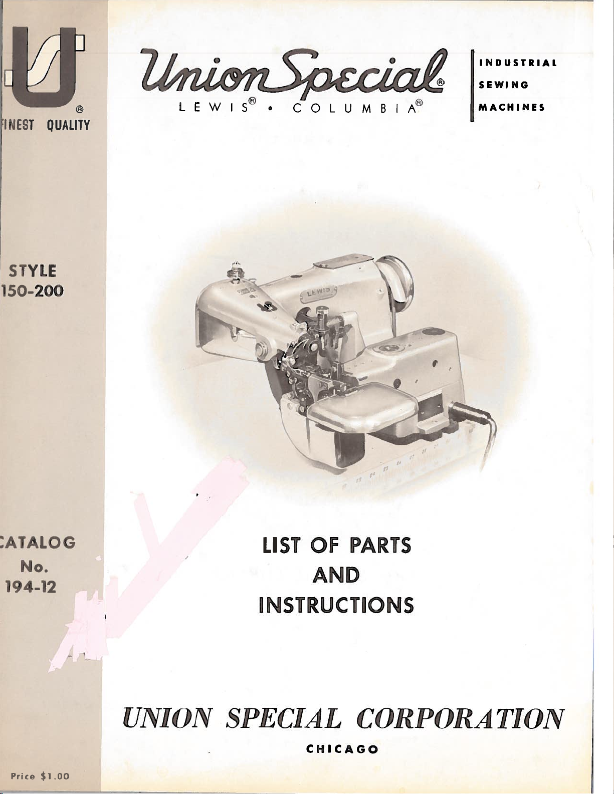
STYLE
I
LIST
)L
OF
-ç
‘4
•1
PARTS
No.
AND
194-12
INSTRUCTIONS
UNION
Price
$1.00
SPECIAL
CHICAGO
CORPORATION
Page 2
Catalog
No.
194-12
ADJUSTING
INST
LIST
Style
First
ItUCTIONS
EQ
R
AND
OF
PARTS
150-200
E
dition
OPE
RATING
Union
Rights
UNION
INDUSTRIAL
Copyright
Special
Re
served
SPECIAL
SEWING
CHICAGO
Printedin[LS.A.
1963
by
Corporation
All
in
Countries
CORPORATION
MACHINES
2
October,
1977
Page 3
Jiitch
plate
top
the
This
Consult
catalog.
This
direction
to
05
itoii
on
UN1(
the
covel’.
catab
atalog
Opposite
catalog
wlule
head
iteIi
)N
)if
No.
applies
seated
S
of
.L5
‘lCJA
the
a
the
as
1
iuiicliine.
i-iiippleiwiit
)f—5,
ilbis
mach
t
specifically
tcght,
at,
the
machine.
II)IN’I’iI’[(’:\’I’lOi”
JiiWIS
machine
The
A
P
0
catalog
ne
ated
page
left,
to
front:,
I)ISC
serial
P1
ACA’I’ION
Sty
Ic
s
the
back,
Operating
RIPTION
carries
number
No.
150—20,
listed
Standard
UI’
of
0
P
94—5
1
fo
each
Style
up
oi
dii’ecton
0
I’
.MACIII\IfS
a
style
each
CATALOG
and
should
all
L
parts
part
by
of
clown,
of
MACIIINE
number
machine
be
not
nun’the
machine
etc.
,
handwheel
which
is
stamped
used
illustrated
c,
name
as
listed
are
given
is
is
in
conjunction
and
awa
stamped
in
or
descrbed
amount
herein.
from
from
the
the
the
in
the
arm,
therewith.
in
reqLlired.
References
ope
cators
operator.
style
under
this
Style
loin
coed
a
trfmming
The
good
grade
Most
painted
The
Use only
lnL,nctht.
The
.
036
of
150—200
edge
finish
device,
machine
of’
straight
of’
the
red.
recommended
genuine
recommended
inch
(.90
shoLild
oiling
mm).
is
front
single
a
belt
mineral
places
operating
UNION
needle
It
loop
i.n
top
feed
oiled
be
on
SPECIAL
for
is
also
Needle
29
BL-065/025
29
BL—075/029
29
BL-l00/040
29
BL—llO/044
needle,
5/16
twice
oil
the
speed
this
available
Type
drive,
of
chainstitch,
or
3/8
daily,
a
ayolt
machine
of
needles.
machine
inch
and
a
OILING
are
SPEED
this
NEEDLES
in
the
finished
stationary
before
viscosity
readily
machine
The
is
following
blindstitch
needles
Type
.025
.
029
.040
.044
widths.
work
the
morning
of
DO
identified
3000
is
29
BL—090/036.
sizes:
Size
inch
inch
inch
inch
support
to
U.
are
(.65
(.75
(1.00
(1.10
machine
This
and
afternoon
125seconds
because
P.
M.
packaged
mm)
mm)
mm)
mm)
for
machine
plate.
under
It
has
producing
at
100
of
the
our
a
is
starts.
blade
a
equipped
Fahrenheit.
fact
they
brand
diameter
double
with
Use
are
name
a
Selection
Thread
To
or
the
would
When
go,
and
Immediately
penetration
should
have
Type
read:
changing
tighten
of
needle
number
100
will
proper
pass
Needles,
clamp
discard
result.
freely
orders
should
needle,
screw
needle
any
size
through
promptly
be
Type
make
securely.
needle
determined
is
needle
and
forwarded.
29
BL-090/036’.
Ci-IANGING
sure
which
eye
accurately
that
may
by
order
in
filled,
Use
the
description
NEEDLES
itisinserted
have
a
size
to
hooked
of
thread
produce
an
empty
in
the
or
blunt
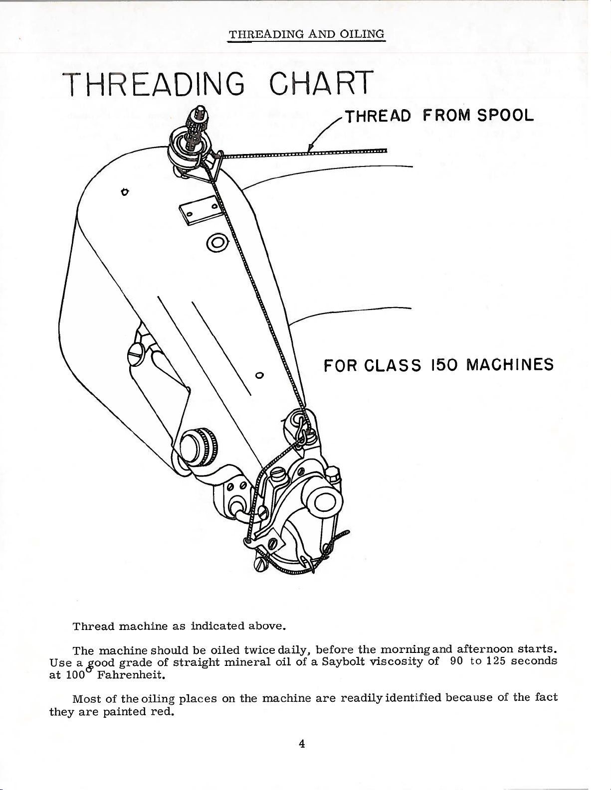
ThREADING
To
highest
thread
posihon.
the
machine,
Thread
turn
machine
hanclwheel
incticateci
as
in
opc
c’atiiig
on
threading
direction
diagram
3
a
on
needle
until
and
weight
good
container,
the
label.
carrier
point,
the
nu:t
on
stitch
needle
of
A
as
page.
material
formation.
a
sample
complete
as
far
improper
carr
icr
as
is
used.
needle,
order
it
will
needle
in
its
Page 4
T11[tEADING
AND
OiLING
THREADING
C
0
a
CHART
THREAD
FOR
CLASS
FROM
150
SPOOL
MACHINES
Use
at
they
Thread
The
a&ood
100
Most
are
machine
machine
grade
Fahrenheit.
the
of
painted
should
of
oiling
red.
indicated
as
be
straight
places
oiled
mineral
on
the
above.
twice
daily,
oil
machine
of
4
before
Saybolt
a
are
the
readily
morning
viscosity
identified
and
of
afternoon
to
90
because
125
of
starts.
seconds
fact
the
Page 5
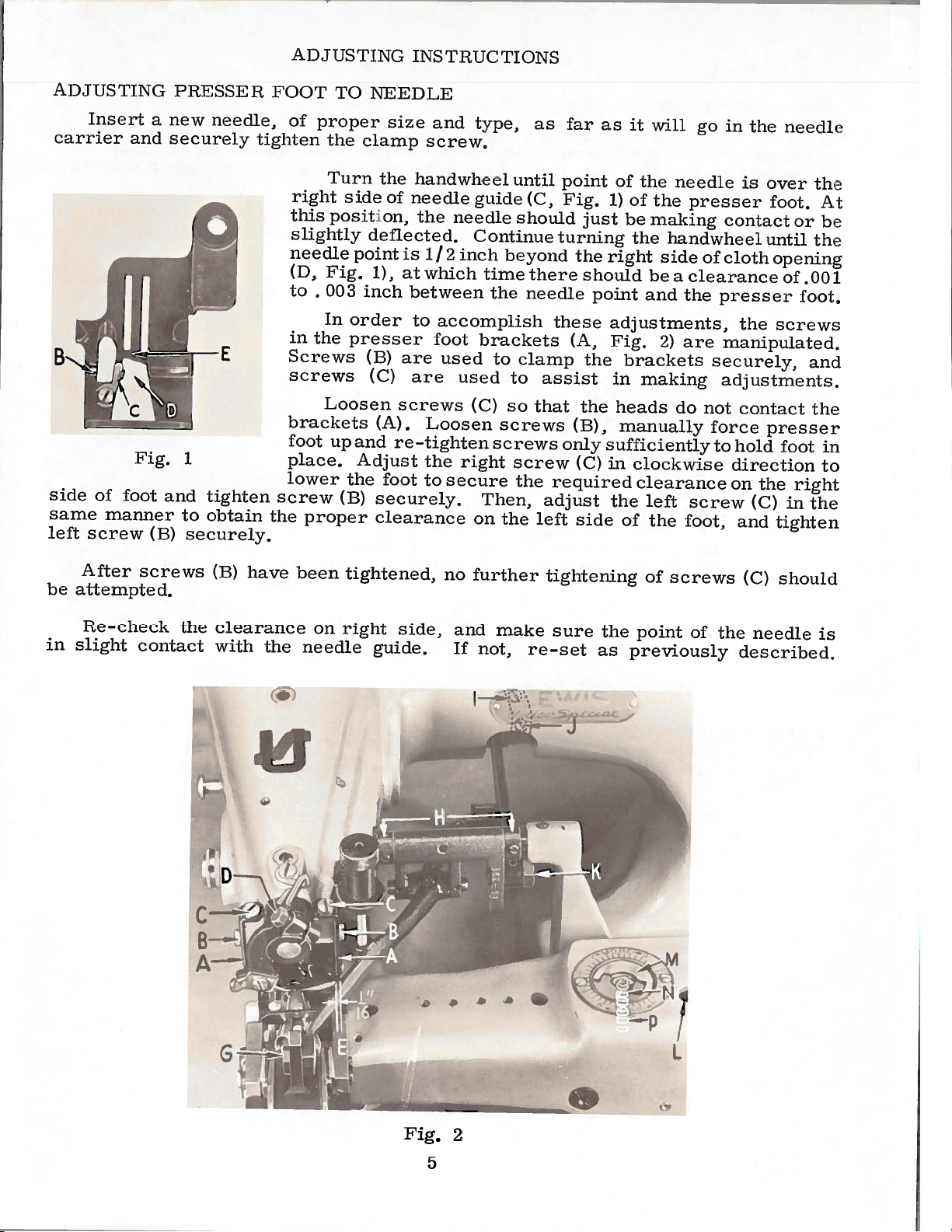
ADJ
caeriei
IJSTING
insert
and
a
new
securely
P1USSI
needle,
H.
I’OOT
tighten
of
ADJUSTING
TO
proper
the
clamp
INST
NEEDLE
size
and
screw,
RUCTIONS
type,
as
far
as
it
will
go
in
the
needle
side
of
same
left
screw
After screws
be
attempted.
Re-check
in
slight
Fig.
foot
manner
contact
(B)
1
and
to
securely.
the
tighten
obtain
have
(B)
clearance
with
screw
the
the
Turn
right
this
position,
slightly
needle
Fig.
(D,
to
.
003
In
in
the
Screws
screws
Loosen
brackets
foot
up
place.
lower
proper
been
on
needle
the
side
of
deflected.
point
1),
inch
order
presser
(B)
(C)
(A).
and
Adjust
the
foot
securely.
(B)
clearance
tightened,
right
guide.
handwheel
needile
the
needle
is
1/2
atwhich
between
to
accomplish
foot
are
used
are
screws
Loosen
re—tighten
the
to
secure
no
side,
and
If
guide
C
inch
brackets
used
(C)
right
on
further
not,
ontinue
beyond
time
the
to
to
so
screws
screws
Then,
the
make
until
(C,
should
there
needle
clamp
assist
that
screw
the
left
re-set
point
lig.
just
turning
the
should
point
these
(A,
the
the
(B),
only
(C)
required
adjust
side
tightening
sure
of
the
of
the
1)
be
making
the
right
adjustments,
Fig.
in
sufficientlyto
in
the
the
as
side
beaclearance
and
2)
brackets
making
heads
manually
clockwise
clearance
left
of
the
of
point
previously
needle
presser
contact
handwheel
or
cloth
the
presser
are
manipulated.
securely,
adjustments.
do
not
force
screw
foot,
screws
the
of
is
over
foot.
until
opening
the
screws
contact
presser
hold
direction
on
the
(C)
and
tighten
(C)
needle
described.
or
.001
of
foot.
and
foot
right
in
the
should
the
At
be
the
the
in
to
is
•w.’:;r
(a)
Fig.
r-.
a
.
‘
S
L
:r.
2
5
Page 6

AI)J(JSTI
FSTlWCTIONS
NC
(Continued)
POS[’[’IONTN(
nI1tri1
extreme
needle
the
the
presser
To
allow
the
above
Turn
extreme
right
If
have
needile
screw
of
top
stud
15
to
ball
the
check
the
left
edge
this
to
,
obtain
the
be
at
in
head
to
stud
the
side
the
left
the
right
the
Vig,
the
previously
retard
or
results.
TI
handwhccl
position.
goove
loot,
this
carrier
setting
handwheel
(E,
not
is
adjusted
extreme
its
needle
(A,
4)
right
down.
position
of
described.
advance
V
NV
(13,
adjustment,
to
is
position.
If
ig.
the
Fig,
that
so
of
of
looper
this
II)[I
In
l’ig,
•be
moved
obtained.
of
2)
case,
the
in
left
crank,
Turn
3).
the
vertical
Re-tighten
the
opening
It
adjustment
operating
in
this
1)
in
operating
The
presser
the
the
following
position,
accessible
the
lower
needle
may
position
anc[
loosen
by
point
travel
with
in
be
even
taping,
of
foot,
of
manner,
loosen
needle
of
end
the
clamp
point
the
necessary
to
c[irection
the
with
needile
direction
needle
the
through
eccentric
its
punch
screw
in
presser
obtain
until
needle
the
clamp
Re—tighten
should
needle
With
clamp
the
hole
is
slot
marks
and
relation
foot
slightly
to
desired
left
until
wil1
the
bald
10
re
point
screw
on
in
to
as
the
side
clamp
the
be
needle
should
of
(D,
needle
1/16
the
Fig.
screw
inch
has
be
looper
in
2)
(D,
has
just
from
reached
the
opening
enough
If
ig.
reached
the
center
2)
the
o[
in
to
when
the
upper
CAUTION!
stud,
shaft
make
crank.
TIMING
Turn
the
at
is
Loosen
that
so
shaft.
AND
the
bottom.
its
This
When
sure
that
ADJUSTING
Fig.
4
handwheel
two
the
timing
setting
adjusting
it
screws
set
line
will
the
seated
is
LOOPER
operating
in
coincides
satisfactory
be
needle
in
against
needle
enters
loop
the
in
its
there
holder
and
(A,
the
with
eccentric
The
motion
the
needle
of
[Jnder
following
Insert
shank
is
(Fig.
the
In
the
on
Fig.
direction
looper
the
for
needle
the
looper
so
spot
thread
normal
looper
the
corresponds
1/64
inch
5).
end
left
looper
5).
until
crank
right
average
ball
motion
that
the
of
conditions,
manner,
of
the
(B,
edge
is
the
needle
being
is
its
in
with
space
main
the
crank,
lV
T
Pig.
the
of
conditions.
timed
long
at
formed.
this
holder
on
flat
between
shaft
there
groove
and
4)
“vu
in
prong
the
timing
holder
position
groove
Fig.
time
so
looper
is
is
in
3
relation
of
the
that
aTT
timing
a
the
in
the
is
the
and
seat
V”
main
the
the
to
looper
largest
adjusted
flat
so
groove,
shaft
crank
main
the
on
that
and
line
6
Page 7

ADJ
IJSTING
INSTRUCTIONS
(C
ontinued)
Variations
advance
Again,
is
over
clear
of
the
presser
On
clear
return
The
sleeve
oc
the
the
spot
needle
foot
continuing
the
right
stroke,
adjustment
and
ietai:d
turn
spot
(H,
the
iii
the
in
eye,
side
should
looper
materials
this
hanclwheel
in
the
the
and
Vig.
the
of
needile.
needle
1)
rotation
of
the
the
holder
timing
the
by
looper
enter
looper
and
to
in
operating
At
and
be
short
no
more
of
the
the
connecting
threac[s
obtain
this
from
prong
handwheel,
opening
crotch
secured
is
than
the
point,
1/16
of
of
rod.
used
desired
direction
the
to
the
1/32
in
the
the
by
may
results,
until
long
3/32
inch
looper
inch.
the
short
presser
looper
manipulation
The
Fig.
5)
and
also
of
vertical
Lateral
loosening
pulling
Vertical
secured
make
the
prong
should
foot,
midway
looper
positions
provides
adjustment
the
or
by
it
long
of
to
the
clear
prong
of
or
the
clamp
adjusting
height
turning
necessary
prong
the
looper
left
the
the
of
and
the
between
the
adjusting
the
a
height
the
of
of
the
bridge
looper
needle,
looper
looper
limited
adjustment.
is
secured
screw
sleeve
adjustment
sleeve.
to
the
should
inner
the
adjusting
sleeve
laterally,
in
slightly
looper
of
should
on
prongs.
amount
(C)
or
just
end
the
its
(B,
by
and
out.
is
in
the
looper
the
looper
required,
adjustment
REAR
operating
moving
the
foot. Set
of
The
to
is
inch.
To
right
the
the
made
FEED
feed
feed
bottom
set
to
with
connecting
to
the
can
it
of
both
POINT
the
direction
the
edge
the
rear
point
surface
of
the
be
rear
left
of
Fig.
desired
secured
the
and
the
feed
is
should
the
stitch
5
rod
connecting
feed,
until
is
cloth
point
1/4
presser
yoke
height.
by
turn
the
1/16
inch
be
length
(D)
turning
rod
the
point
inch
opening
so
that
in
back
flush
foot.
set
and
If
only
the
and
handwheel
of
to
in
the
of
with
This
at
7
turning
by
a
adjusting
adjusting
the
the
the
short
the
and
adjustment
stitches
also
to
sleeve.
adjustment,
made
slight
in
needle
right
presser
prong
needle.
parallel
The
adjusts
a
greater
If
amount
sleeve.
the
per
looper
the
by
the
sleeve,
is
of
the
extent
looper
the
loosening
connecting
of
Final
holder
looper
is
initial
height
connecting
vertically,
than
radically
the
rod
setting
adjusting
the
adjustment
clamp
(E),
adjustment
involves
out
screw
rolling
rod
but
of
is
is
The
(A,
a
feed
Fig.
rm.
6)
point
holding
is
the
adjusted
feed
by
point
means
to
the
of
7
two
feed
screws
driving
Fig.
6
Page 8

i\DJtJS’I’iNC
[NSLRLC[iONS
(Cont:inucc[)
A’I’l
l’I
against
tension
the
will
needle
controlled
the
counterclockwise
P1
IH)
When
rthlc
There
needle
not
Check
Pressure
cylinder
the
the
platen
on
be
penetrates
clockwise
The
VO
yielding
be
in
in
RIDGE
should
opening
noted
as
Adjustment”.
right,
the
to
small
1/16
former
from
inch
over
ridge
distance
the
is
directly
P”
[cud
hottoni
is
the
platen
must
to
by
he
makes
[ormed
see
on
the
(A,
the
acts
RMING
located
presser
the
subsequent
As
the
should
the
radius
when
the
point
of
controlled
will
enough
its
for
that
material.
the
nuts
two
1ig.
increases
reverse,
DISC
ridge
in
needle
the
forward
point
the
of
the
disc.
on
is
presser
the
compensate
pressure
penetration,
looper,
the
feed
the
feed
in
Turning
7).
the
forming
the
center
foot
paragraph’
is
position
set
be
the
of
nose
needle
its
by
platen
the
and
traveling
so
needle
on
[ucc[iLIg
two
resulting
platen
back
them
tension,
disc
of
folder,
‘Folder
of
that
disc
the
point
Loot
springs
[or
appiiec[
if
is
of
the
the
the
to
is
stroke,
and
varying
the
clamps
which
keep
to
material
skipped
in
a
the
iced
thicknesses
the
piece
[cccl
point
should
material
moves
stitches,
of
platen
under
adjusted
be
of
with
newspaper
presses
spring
material.
from
the
A
so
moving
needle,
before
B
work
the
pressure,
that
when
a
point
tlie
ioop
of
NOTE:
forming
play
end
there
pages
In
set
the
crank,
direction
center
center
nose
crank;
take
If
plate
ridge
disc
the
in
firmly.
disc,
in
end
is
and
9
order
screw
accessible
until
the
of
the
of
the
of
also
all
up
there
holders,
forming
assembly,
ridge
Before
the
play
10.
to
(F,
presser
presser
disc
the
the
is
forming
sure
be
cradle
see
adjust
the
and
set
end
need
a
remove
disc
care
adjusting
Catalog
Fig.
through
point
the
screw
play
to
assembly.
must
disc
that
(H,
the
7)
of
foot.
foot
in
the
there
Fig.
disc,
in
the
the
and
point
(F,
the
remove
nut
be
holder,
the
No.
loosen
the
hole
needle,
Position
there
of
Fig.
ridge
the
(B,
Remember
taken
ridge
is
7).
194-5,
collar
the
forming
ridge
Fig.
so
Then
no
If
(L,
when
the
is
needle.
7)
in
8)
that
re-assemble
(G,
Fig.
traveling
disc
16
1/
collar
forming
on
the
8
Fig.
2).
manually
inch
disc
the
when
key
also
7);
Turn
the
to
between
Re-tighten
Fig.
(G,
shaft.
assembly,
disc
ridge
former
re-assembling
flange
the
in
the
the
so
nut
Fig.
clamp
the
handwheel
right,
that
the
the
and
7)
shaft
engages
(B,
7
is
it
small
clamp
set
the
Fig.
screw
line
in
lines
radius
screw
the
depress
and
ridge
with
8)
operating
in
up
collar
remove
and
in
with
with
of
in
feed
the
forming
the
slot
tighten
the
the
the
the
the
to
the
Page 9

—
I
cssure
pItiier
(hiieraLl.y,
helween
sHaft
III
lowers
huuig
depth
forming
in
(Fig.
)GE
The
of
place.
sewn.
rod
the
VO
dialed
the
needle
disc.
(C,
the
Li).
VILNG
R
ridge
to1)
directly
is
Vig.
correct
of
the
DISC
regulator
forming
The
word
penetration.
E
Re-assemble
ADJUSTING
applied
Li)with
pressure
plunger
REGULATOR
(lvi,
disc
More”
Fig.
8
the
INSTRUCTIONS
to
tipper
is
holder
Fig.
2)
to
get
indicates
Id
the
set
the
yielding
(D)
nut
obtained
and
the
located
the
correct
more
114
screw
and
when
underside
on
(N)
(Continued)
ridge
locking
there
top
of
needle
depth,
amount
in
order
from
disc.
turning
in
the
possible
regulator.
over
and
the
the
(N,
Fig.
the
the
mounted
the
and
set
forming
in
of
the
and
The
striking
The
More”
The
the
the
ridge
case,
Fig,
2)
cradle
ridge
needle
tightly
disc
place
5/32
is
the
head
cylinder
penetration
“Less’
regulator
the
that
to
protect
adjustment
the
regulator
to
stop
needle
center
needle
former.
remove
and
2)
underneath
(H,
forming
and
adjust
just
by
with
inch
of
base
indicates
also
disc
the
the
ridge
direction
pin
point
of
should
the
adjust
Fig.
grazes
lock
to
adjusting
lower
clearance
the
raises
in
limits
canbe
needle
is
(M,
as
inside
should
the
just
If
this
set
screw
that
in
7)
disc
screw
the
screw
nut
plungce
the
work
raised
point
forming
made
Fig.
far
of
ridge
graze
is
screw
contacts
which
shaft
so
ridge
the
(E),
and
less
the
by
2)
as
the
be
not
(P,
is
that
(P)
FOLDER
The
the
centerline
With
height
needle
the
Rotate
extreme
mately
increasing
tighten
center
knife
should
NOTE:
the
opening
the
folder,
ADJUSTMENT
folder
the
relationship.
is
the
left
1/16
the
the
folder
over
block
be
taken
in
If
should
of
front
traveling
handwheel
end
inch
1/16
the
ridge
mounting
to
If
the
the
this
the
top
of
from
with
move
ridge
presser
is
be
needle
feed
The
to
stroke.
inch
the
former
screws
not
set
and
and
needle
the
in
the
needle.
dimension.
two
the
block
former
foot,
the
case,
so
that
located
right.
operating
Insert
locking
and
(C,
the
front
its
in
folder
point
in
Fig.
perpendicular
has
position
the
A
the
been
ridge
removed,
should
folder
slightly
With
screws
opening
7)
the
direction
the
and
correctly
former
ridge
9
edge
center
just
and
wider
folder
(13,
of
move
check
to
should
former
approximately
is
the
of
the
clear
position
and
position
belt
resting
Fig.
the
presser
the
the
line
in
set
opening
ridge
the
ridge
the
front
loop
on
If
of
feed.
the
foot,
accordingly.
up
7),
block
relation
line
accordingly.
can
with
in
former
forming
the
the
folder
to
1/16
presser
needle
edge
be
obtained
ridge
loosen
the
the
inch
-
disc
approxi
former
does
the
center
center
from
foot.
needle
at
the
not
two
Care
as
by
of
of
Page 10

l’I1(
)N’l’
TOP
AI)J
1ih’I:LNC
LNSH’I1LC’l’i
)NS
((ciit.iinied)
Asomhte
(dy.
Cli
)ck\\
oh
lnert
inch
003
•
AppLy
folder
the
ol
[ho
obtain
NOTE:
main
e
Lii
Ific.
free
direct±on,
01
ajntiu
The
position
slot,
loosen
feed
the
lower
of
top
1/8
4
slot,
Normally,
the
With
adjust
S(
base.
Lot
s
this
2)
of
ned,
If
lock
driving
the
S.P.I.
the
the
I(l.oase
oLe
Iingei’
(‘elTtei
shaft
the
in
any
travel
of
is
it
rocker
driving
piece
a
a.i.’an
\V
the
in
sett
It
hinds.
i.ocates
the
desirable
nut
slot,
When
stitch
the
teed
lout
1(’e(1
cc.
prenre
i.e
hi.
P
piolig
ng,
i
may
when
eccentrjc
the
of
feed
(I
slot.
arm
the
length
arm
arm
lift
[cod
of
do
ed
acij
he
The
on
driving’
Fig,
in
stitch
the
is
located
as
Li
ItO
paper
ng
dog,
oL
ust
necessary
making
and
first
Ilat
a
front
increase
to
2)
To
slot.
arm
is
set
folloxvs:
Iced
to
I)iSSu1te
hetWoen
the
laLse
T
[gliten
shouLd
colLars
the
position
toj)
to
So,
teed
t\VO
screw
on
feed
arm
raise
and
shorten
\\‘lien
length
at
is
approximately
the
in
the
in
iu.in
to
above
the
is
in
the
the
is
the
center
desired
feed
regulated
the
with
(oIaltiuig
by
Iced
clog
I
ha
feed
he
Located
le
on
adjustment.
when
feed
secureLy
ed
to1)
shaft.
is
Screw
adjust
eccentric
(I),
main
stitch
driving’
stitch
arm
approximately
bottom
8
the
of
position,
screw
(log
shank,
SO
rocker
front
so
by
rocker
length,
arm
length.
at
of
S.
slot,
(C,
adjusting
and
hoLding
that
in
center
that
turning
It
the
in
the
the
I.
P.
loLdet’
screw
this
in
(ii,
feed
Loosen
the
is
Fig,
knob
the
(0,
position.
of
Fig.
drive
teed
the
essential
Do
2),
(K,
obtain
to
feed
Pig.
opening
accordingly.
2)
eccentric
the
drive
hariclwheel
that
not
tighten
Pig.
two
6)
appro>n.niate[y
flat
dog
is
2)
folder.
in
screws
strap
in
this
(‘minter—
against
the
at
located
operates
operating
timing
(I,
se—
top
To
on
J
be
is
locate
9)
bar
dog
Raise
lift
against
by
feeding
re
the
the
ad
Jotate
inthe
feed
center
dog
gulating
underside
connecting
the
feed
Re-apply
justing
3/32
block
driving
knob
handwheel
its
of
i/s
to
(A,
the
of
regulator
rod
arm.
sufficient
(B,
travel
Fig.
feed
Fig,
until
inch
the
towardthe
and
9)
driving
block
Lock
tension
to
6)
so
in
insure
top
slide
that
arm,
this
(B,
to
front
operator.
feed
the
contacts
it
and
Fig.
position,
feed
proper
feed
action,
TRIMMING
The
the
for
of
size
Refer
width
of
MECHANISM
width
upper
folder
the
to
finished
and
chart
of
trim
being
belt
lower
on
is
used
Page
loops,
determined
knives,
and
for
15
weight
the
The
the
material
parts
material
of
the
by
selection
to
use
being
be
or
of
of
these
sewn,
removed
type
10
spacer
of
pins
spacers
and
[older,
Fig.
added
and
is
9
spacer
relative
when
plates
to
changing
the
Page 11

>1’
Al
)TUST[N(
I
1K
Ni\/
R
I
[NSTl
I
Cl’i(
)\S
(Continued)
attaching
cessu
p
space
no
gap
tension
Attach
re
between
NOTi:
between
Fig.
Adjust
screws
to
10
applied
lIpl)ei
the
riThe
tension
top
the
may
knives,
((‘,
chip
o[
chip
deftectors
on
lig.
deflector
[older
deflectors
It
the
upper
slightly.
possible,
LOWER
Turn
stroke.
position
(The
elongated
resharpening.
Loosen
turn
above
connecting
bottom
knives
vary
with
chip
&
(3
and
and
should
INlVES
Loosen
knives
by
the
deflector,
10).
and
knives
cutting
should
the
be
knives
iNormally
to
give
handwheel
nuts
edge
turning
thickness
When
edges
be
upper
noted
from
maximum
knife
to
their
slots
on
rod
of
and
securing
and
assembled
knives.
that
the
the
clockwise
attaching
in
ball
until
top
two
of
correct
lock
in
the
of
the
top
of
knives
clearance.
maximum
the
joint
front
knife.
screws
cloth
knives,
place.
knives.
to
location
the
are
until
screws
low
knives
connecting
edge
of
Tighten
(E,
to
be
spacing
apply
This
the
knife
folder
positioned
lower
position
are
lower
nuts.
Fig.
trimmed.
of
(D,
rod
will
block
the
base
knives
Fig.
to
knife
6).
plates
a
slight
insure
so
cutting
can
as
far
are
&
6
and
retighten.
compensate
(D,
Fig.
is
The
amount
with
there
be
at
1/32
ipwacd
proper
edge
varied
up
top
10)
7)
fou
is
of
as
of
and
for
and
inch
of
the
collar
operate
collar
STITCH
near
shaft
down,
down,
shorten
to
ing
Release
Proper
in
The
the
with
which
turn
the
alignment
(E,
the
machine
position,
LENGTH
stitch
head.
numerals
the
the
stitch.
desired
the
knob.
Fig.
length
Open
will
handwheel
7).
slowly.
being
the
which
engage
As
amount
Stitch
of
To
is
you
the
bottom
obtain
The
careful
regulated
top
cover
indicate
slot
a
away
turn,
of
stitches
range
knives
the
knives
not
by
on
the
in
from
observe
of
the
to
the
the
the
per
correct
will
disturb
knob
number
feed
you
the
inch
machine
to
the
automatically
arm
mechanism.
to
lengthen
indicator
top
knives
alignment,
the
alignment.
(13,
Fig.
and
observe
of
stitches
appears
is
until
from
loosen
on
3)
per
the
directly
6
is
align
the
the
While
stitch
the
to
obtained
themselves.
arm
feed
inch.
and
number
under
8
stitches
collar
of
indicator
Press
holding
by
positioning
screw
the
toward
correspond
the
indicator.
per
machine
on
the
the
you
inch.
and
Lock
the
knob
knob
to
11
Page 12

zj
—-
-
4
C-’
/
I
L)
C
_
I
CD
CO
—I
,_i
(_____
1
—--,
C
(-)
C
CO
Page 13

1
liii
ipieselit
or
niam
Use
1-110-235
AS1
;:1153
1160
‘1750
6042
::22652
35751
38242
39543
‘20-31
*
Not
ails
I
lie
precediig
blow
asseoihly.
Catatng
Part
0.
8—137
8—138
14—394
14-432
ci
-
18—533
18—533
13-764
18—
18-951
18—1075
20-80
20—148
20-
21-53
21-427
22-262
22-319
22-320
22-321
32-36
32—302
33—156
13-700
39-141
45-464
46-201
47—132
43-130
50-236
50-237
57—52
70—73
107-44
110-314
115-160
115—161
119-31
119-82
26
158-26
158—27
444-318
13-313
20-122
21-341
26—
152
44-318
99-304
667
D-24
L
L
L
A
D-12
F
38
89
0
N
shown
400
873
149
ilinstrateil
[lie
lie
box
in.
Il
•
the
on
parts
page,
aml
15tH
Top
Top
Feed
Connecting
Bottom
Bottom
Washer,
Slide
Slide
Ridge
Front
Screw,
Nut,
Screw,
\\
Screw,
Loopnr
Feed
Thrust
Nnt,
picture
on
that
ale
part
are
imlirated
for
.5
Knife
Knife
l3idr’e
Slain
Screw,
Screw,
Screw,
Plug
Screw,
Screw,
Screw,
Screw,
Nnt,
for
Nnt.
for
Locking
Tension
Presser
Spring
Presser
Pin,
for
Pin,
for
Arm
Cover
Cever,
Anxiliary
Scre
Drive
Front
Front
Connecting
Driving
lKnife
Spring
[landwheel
Soring
Flange,
Knife
lKnife
Lift
Plate,
Plate,
Screw
Not
Spring--Plunger
Dis
Disc
Fcted
for
asher,
Set
Spot
Rocker
for
plate
lie
precedino
nsed
nnmhers
ati
Onard,
Board,
Vernier
Shaft
for
fer
for
for
for
for
14—394
1$—
Nut,
Soring,
Spring:
l’ii
Pit
driving
driving
for
Pin
Feed
Peed
Crank,
Support
Support
Barrel
for
Knife,
Knife,
for
Former
Plunger
for
365
for
for
for
Becker
Screw
Screx
Bearing
Ne,
on
pai’t
5
left
riplit
119—68
45-464
38242
for
115-160
158-:
47-132
1079
for
Plat
50-236
Feed
Cellar
l3ar
liocke
Rod
Bracket
ridge
Spacing
Spacing
Rogulater
Rod
left
right
18—873
left
right
Assembly
Rocker
50-237
L
119-68
22652
50-286
Shaft
Shaft
4118-15
on
page
Styte
contained
on
Ins
nol
Shaft
C
machine
7tt—73
fur
lower
lower
Dring
---
for
Bracket
former
Plate,
Plate,
Regulator
Helde
Shaft
on
D-12
Slasher,
12.
and
1511—2011
pa;
itinst
on
Slyle
lower
lower
Style
Stop
fnl.tnwing
wit
by
tat
cii
150—200—5/16
arm
knives
knives,
knives,
Eccentri
knive
shaft
for
for
Block
150-200-3/3
Colla
for
18—1075
lint
hin
biolenliin:
and
on
on
Style
Style
po$i,
are
lint
a
lox
are
described
Des
Ci
Style
Style
150-200-5/16
150-200-3/8
-——
that
are
ilesciLhed
Lised
on
components
their
descriptions
here.
01
P[i(
150—200—3/8
150-200-
5/16
on
tins
page
and
on
page
opposite
of
Amt
15
he
15tH
211.
of
[lie
part
nniwber
Linder
list
lie
descri
ed
lion
HeLl.
1
1
1
1
4
1
1
1
1
2
1
1
1
1
‘1
1
9
1
1
1
1
1
1
9
1
1
1
1
1
1
1
1
1
1
9
9
1
1
1
1
1
1
1
1
1
1
1
1
1
9
1
4
9
9
9
1
1
1
1
1
13
Page 14

a
‘-i-i
L
/
I.
OD
‘
tr
1
j
)
I
IIt•
)
c-J
(A)
(j
Page 15

P-u
No.
16—
1816—1142
33:3
23—
:334
23—
24-323
41-42
41-49
50-
210
405-
531
5—561
6-73
18—
(43
0431—185-5/16
t431-1853/6
‘431-1
t4311863/8
463—23—1
20-60
468—2:)
1132
L
1160
L
1183
L
499-303
22894
Al)
715
732
66-5/i
plate)
finish,
iinlsh,
inch
finish
finisi
sa
A
mt
{
eq.
1
1
1
1
1
1
1
1
1
1
1
1
1
1
1
for
for
Style
Style
1502005/16---
130-200-3/6
1
1
1
1
1
1
1
0
1
9
-
MISC
Screw,
Screw,
Screw,
Front
Peed
Feed
Thread
fhread
Iced
Presser
Feed
Point
Plate
Plate
Presser
Needle
for
for
for
Guide
(Icicle
loot,
23-333
23-334
499-303
Point
Holder
comoletc
6’oot
Guide
Dracket
(not
1ILLANIN)US
identified
Res
on
PARTS
criotion
pJcturr
Screw
I
‘older,
Folder,
6
Folder,
Voider,
Tension
marked
marked
marked
marked
Post,
‘A”,
‘H”,
“C’,
“D”,
complete
split
split
sotid
solid
lyne,
type,
type,
type,
5/16
:1/8
for
fox’
inch
inch
s/lu
3/8
inch
Nut
Tension
Tension
Staff
Spring
Nut
Peed
Screw,
Tension
Plate
for
His
Holder,
folde
right
If
below
sew
to
431-135-5/16.
Type
Material
Livht
to
L:ight
to
Light
to
Extra
Extra
Extra
Light
Lighi
I
a
customer
indicates
5/16
of
Med.
.\Ied.
Sled.
cay
inch
the
desires
belt
narts
loops
to
sew
to
be
removed
made
Folder
431—185—3/11
Slacked
Split
“13’’
Folder
431-186-5/16
Marked
Solid
‘‘C’’
i”older
431—1t16-3/6
Marked
Solid
“H”
older
431—185—5/16
Parked
Split
I
Mlder
“A
4:31—166—5/16
Marked
Solid
‘‘C’
Voider
431-185-3/8
Parked
Sptit
“11’
1’oider
a
different
of
light
and
to
l’Pnish
5/16”
:3/8”
weight
adchd
ncslium
:3/3’’
5/16”
3/8’’
5/16
material,
toastandard
weight
(4)
(1)
(2)
(1)
(1)
(4)
(1)
(2)
(1)
(2)
(1)
(2)
(1)
(1)
(4)
(i)
a
different
190—200-3/16
material
Remove
16—400
22—321
110—265
411-165-5/16
431-169-5/16
16—400
22—321
110—265
431-183-5/16
110—285
22-321
110—265
22—621
431-1855/16
16-400
431-
169-
using
5/16
folder
a
or
machine
split
finish,
type
(4)
(1)
(2)
(1)
(1)
(4)
(1)
(2)
(1)
(2)
(1)
(2)
(1)
(1)
(4)
(1)
the
thaL
is
folder,
I’ll
With
1750
L
22—320
110—314
431-185-3/8
431-166-5/16
1750
L
22-320
10—
1
314
431-166-:3/8
110—314
22-320
110—314
22-320
431i365/l6
1750
L
431-169-3/6
set
chart
up
No
Extra
I
Folder
Voider
hay
can
can
uc
u-Os)
be
used
for
for
431-
Parked
Solid
light
:3
186-1/8
Voider
i-a
and
0
D”
light
and
medium
light
3/6’
to
rnedluLn
or
extra
heavy
(4)
(1)
eughi
w
weight
16-400
-131-169-
:natural,
maLe
15
s/lu
rial,
depending
depending
(4)
(1)
on
on
1750
421-136-
shims
shims
L
:3/8
used
used
Page 16

I
t
E
WORLD’S
SI
ATLANTA,
BOSTON,
CHICAGO,
DALLAS,
FINEST
UNION
facilities
aid
equipment
Special
tory
promptly
tion,
serve
-C.’
QUALITY
*
SPECIAL
throughout
in
you
for
representatives
trained
and
there
is
Check
you.
GA.
MASS.
ILL.
TEXAS
maintains
selection
the
your
are
and
efficiently.
a
Union
with
liii
INDUSTRIAL
world.
the
of
particular
service
and
to
able
Whatever
Special
today.
him
MONTREAL,
TORONTO,
BRUSSELS,
LEICESTER,
o
SEWING
and
sales
offices
These
right
the
operation.
men
your
serve
your
Representative
MACHINES
service
will
sewing
Union
fac
are
needs
loca
to
CANADA
CANADA
BELGIUM
ENGLAND
o
7)
ANGELES,
LOS
YORK,
NEW
PHILADELPHIA,
UNION
400
N.
CAL.
Y.
N.
PA.
Representatives
industrial
SPECIAL
FRANKLIN
and
cities
distributors
throughout
ST.,
all
world.
important
ENGLAND
FRANCE
GERMANY
LONDON,
PARIS,
STUTTGART,
in
the
CORPORATION
CHICAGO,
ILL.
60610
/
 Loading...