

Page 1
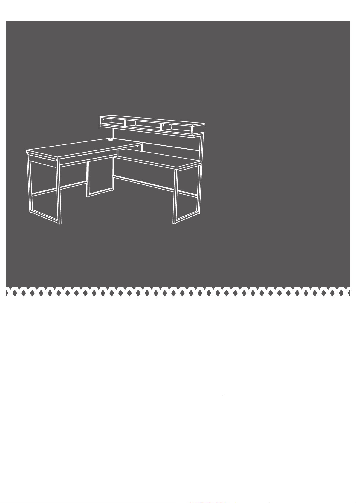
L-Shaped Desk
Sit and surf.
NOTE: THIS INSTRUCTION
BOOKLET CONTAINS IMPORTANT
SAFETY INFORMATION.
PLEASE READ AND KEEP FOR
FUTURE REFERENCE.
English pg 1-27
Français pg 28-31
Español pg 32-35
Page 2
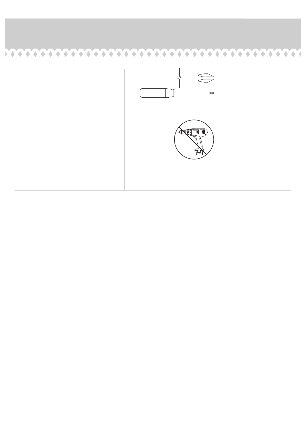
Table of Contents Assembly Tools Required
Part Identifi cation
Hardware Identifi cation
Assembly Steps
Français
Español
Safety
Warranty
4-5
6-27
28-31
32-35
36-38
39
3
No. 2 Phillips Screwdriver
Tip Shown Actual Size
Skip the power trip.
This time.
Page 2
Page 3
Now you know
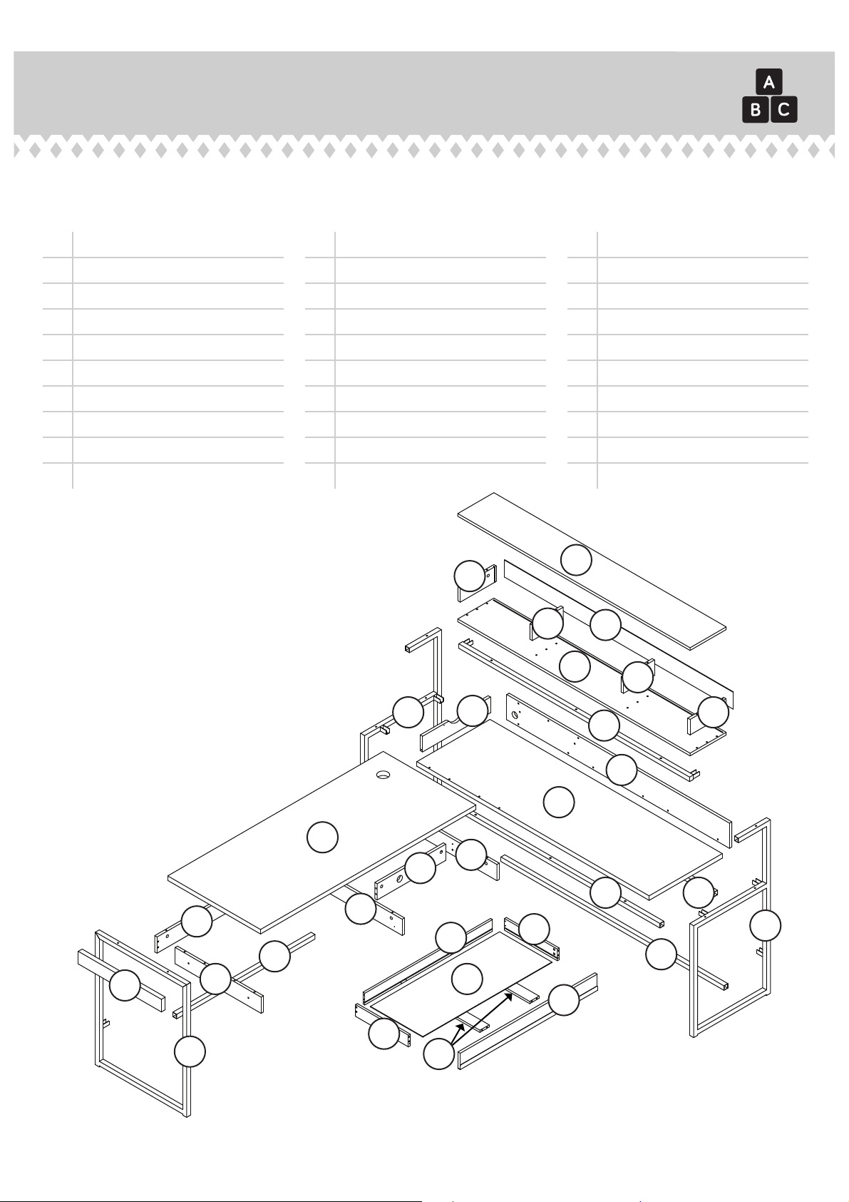
Part Identifi cation
å While not all parts are labeled, some of the parts will have a label or an inked letter on the edge
to help distinguish similar parts from each other. Use this part identifi cation to help identify similar parts.
our ABCs.
A DESK TOP (1)
B RETURN TOP (1)
C END MOLDING (1)
D LEFT END (1)
E REAR PANEL (1)
F FLIP DOWN DOOR (1)
G UPRIGHT (1)
H RIGHT END (1)
J RETURN BACK (1)
K HUTCH BOTTOM (1)
L HUTCH TOP (1)
M LEFT HUTCH END (1)
N RIGHT HUTCH END (1)
O LEFT HUTCH UPRIGHT (1)
P RIGHT HUTCH UPRIGHT (1)
Q HUTCH BACK (1)
R DRAWER FRONT (1)
S LEFT DRAWER SIDE (1)
T RIGHT DRAWER SIDE (1)
U DRAWER BACK (1)
M
V DRAWER BOTTOM (1)
W DRAWER BRACE (2)
X RIGHT RETURN FRAME (1)
Y LEFT RETURN FRAME (1)
Z DESK FRAME (1)
AA LOWER RETURN MOLDING (1)
BB UPPER RETURN MOLDING (2)
CC HUTCH MOLDING (1)
DD LOWER DESK MOLDING (1)
EE DIVIDER (1)
L
O
Q
K
Y
F
P
N
CC
J
B
A
H
EE
BB
BB
G
E
U
DD
C
D
V
T
AA
X
R
S
Z
W
Page 3
Page 4
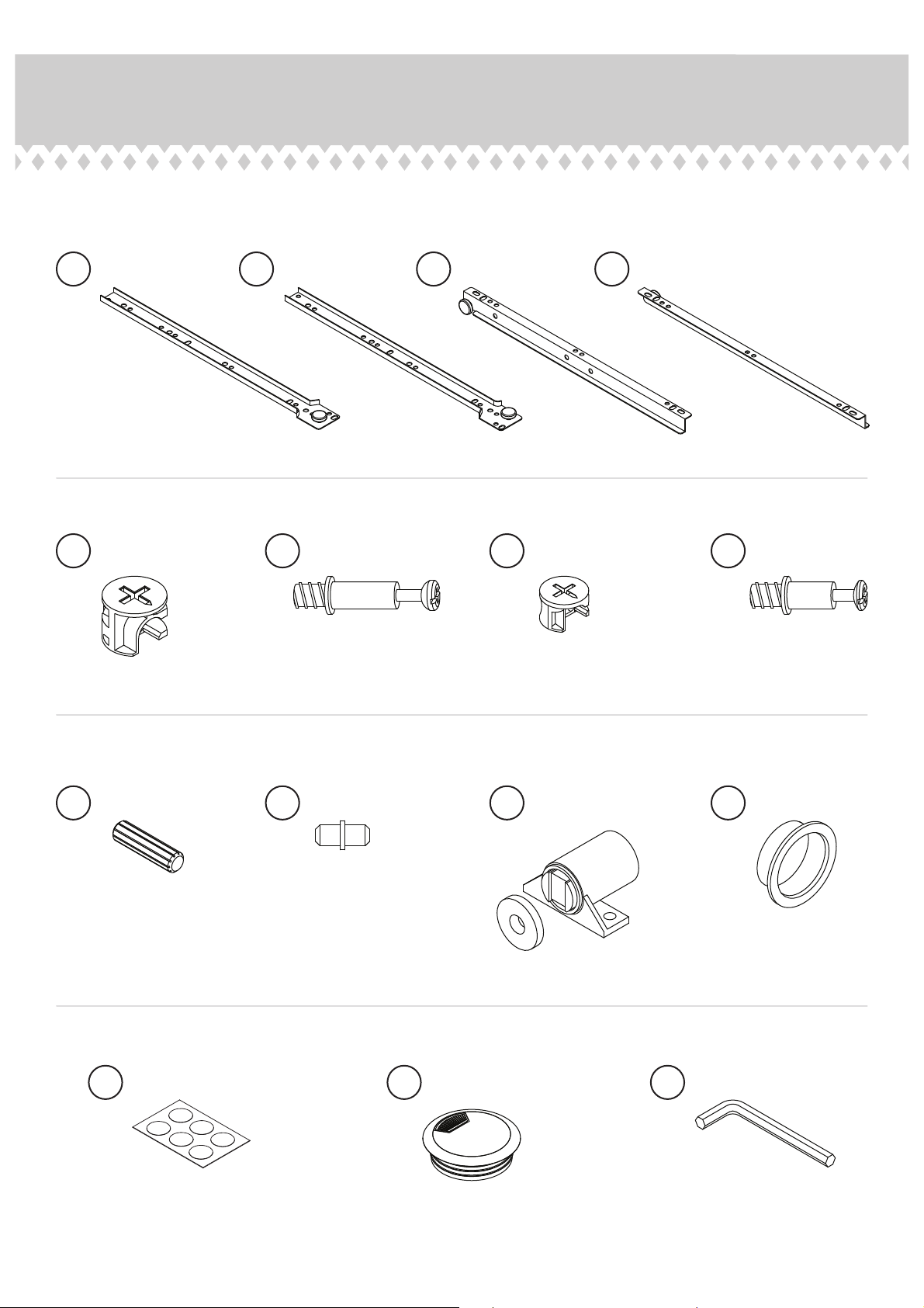
Hardware Identifi cation
å Screws are shown actual size. You may receive extra hardware with your unit.
CABINET RIGHT - 1
1
LARGE HIDDEN
5
CAM - 19
CABINET LEFT - 1
2
LARGE CAM
6
SCREW - 19
DRAWER RIGHT - 1
3
7
4
SMALL HIDDEN
CAM - 8
DRAWER LEFT - 1
8
SMALL CAM
SCREW - 8
9
WOOD DOWEL - 22
13
APPLIQUE CARD - 6
10
METAL PIN - 2
GROMMET
14
WITH CAP- 1
11
MAGNETIC
CATCH - 1
L-WRENCH - 1
15
12
GROMMET - 3
Page 4
Page 5
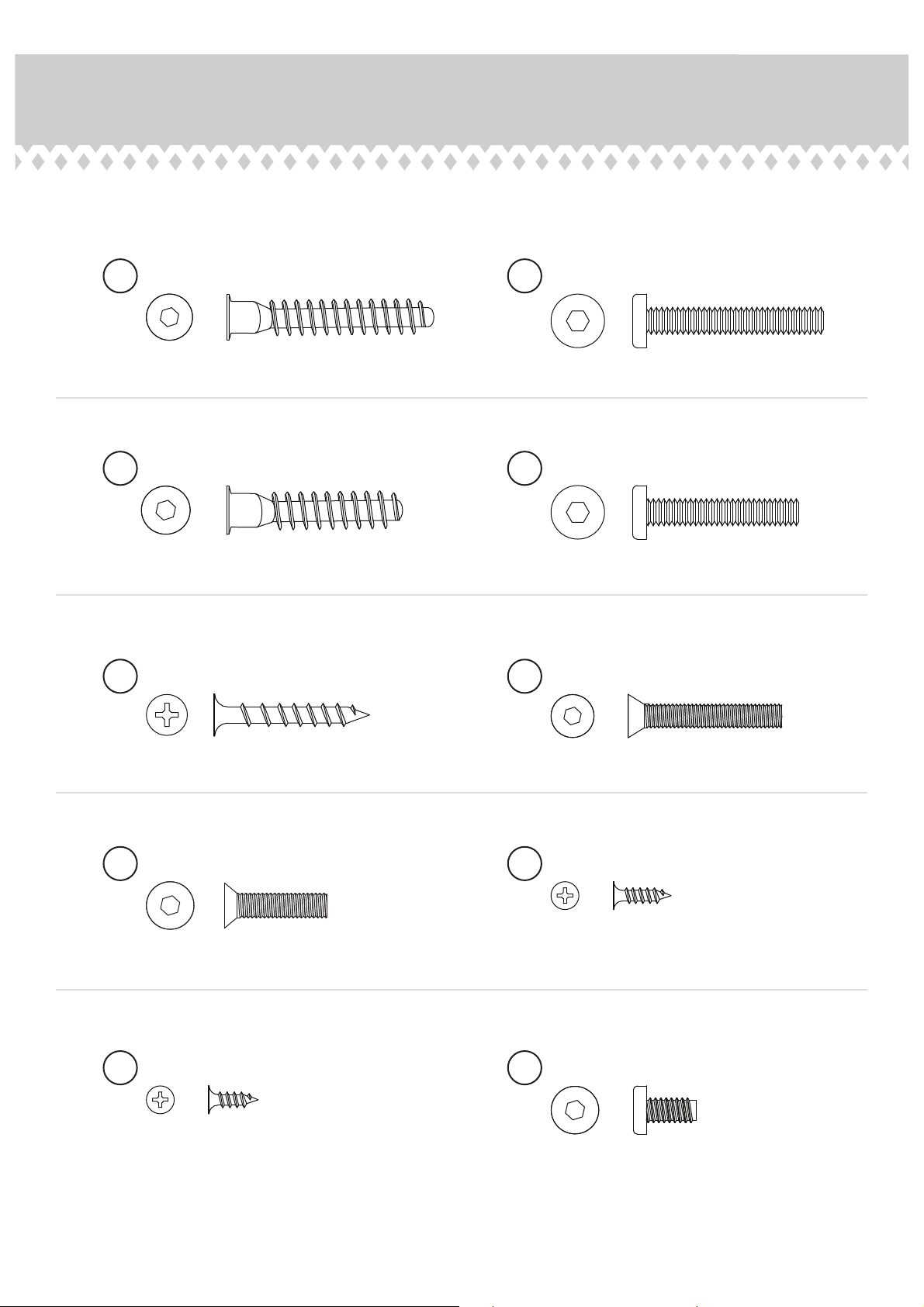
Hardware Identifi cation
å Screws are shown actual size. You may receive extra hardware with your unit.
20
BLACK 1-7/8" HEX HEAD SCREW - 2
22
BLACK 1-1/2" HEX HEAD SCREW - 19
24
BLACK 1-3/8" FLAT HEAD SCREW - 8
21
BLACK 1-9/16" HEX HEAD SCREW - 10
23
BLACK 1-3/8" HEX HEAD SCREW - 5
25
BLACK 1-3/8" TAPERED MACHINE SCREW - 2
26
BLACK 1" TAPERED MACHINE SCREW - 5
28
BLACK 1/2" FLAT HEAD SCREW - 12
27
BLACK 9/16" FLAT HEAD SCREW - 3
29
BLACK 7/16" HEX HEAD SCREW - 20
Page 5
Page 6
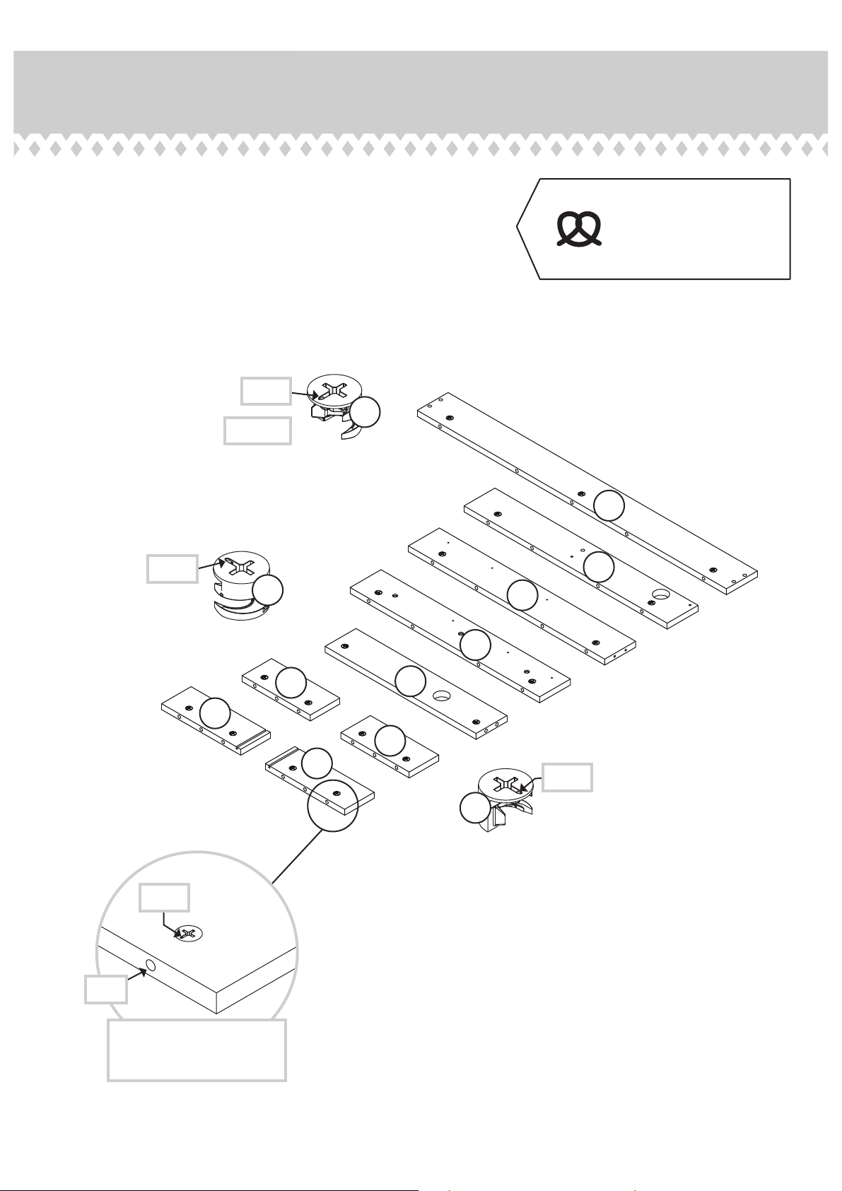
Step 1
Assemble your unit on a carpeted fl oor or on the empty
å
carton to avoid scratching your unit or the fl oor.
Push nineteen LARGE HIDDEN CAMS (5) into the LEFT
å
END (D), REAR PANEL (E), UPRIGHT (G), RIGHT END (H),
HUTCH ENDS (M and N), HUTCH UPRIGHTS (O and P),
and DIVIDER (EE).
Arrow
5
(19 used)
Some assembly
(and snacks) required.
E
Arrow
Arrow
H
5
G
D
P
EE
N
O
M
Arrow
5
Page 6
Hole
The arrow in the HIDDEN
CAM must point toward the
hole in the edge of the board.
Page 7
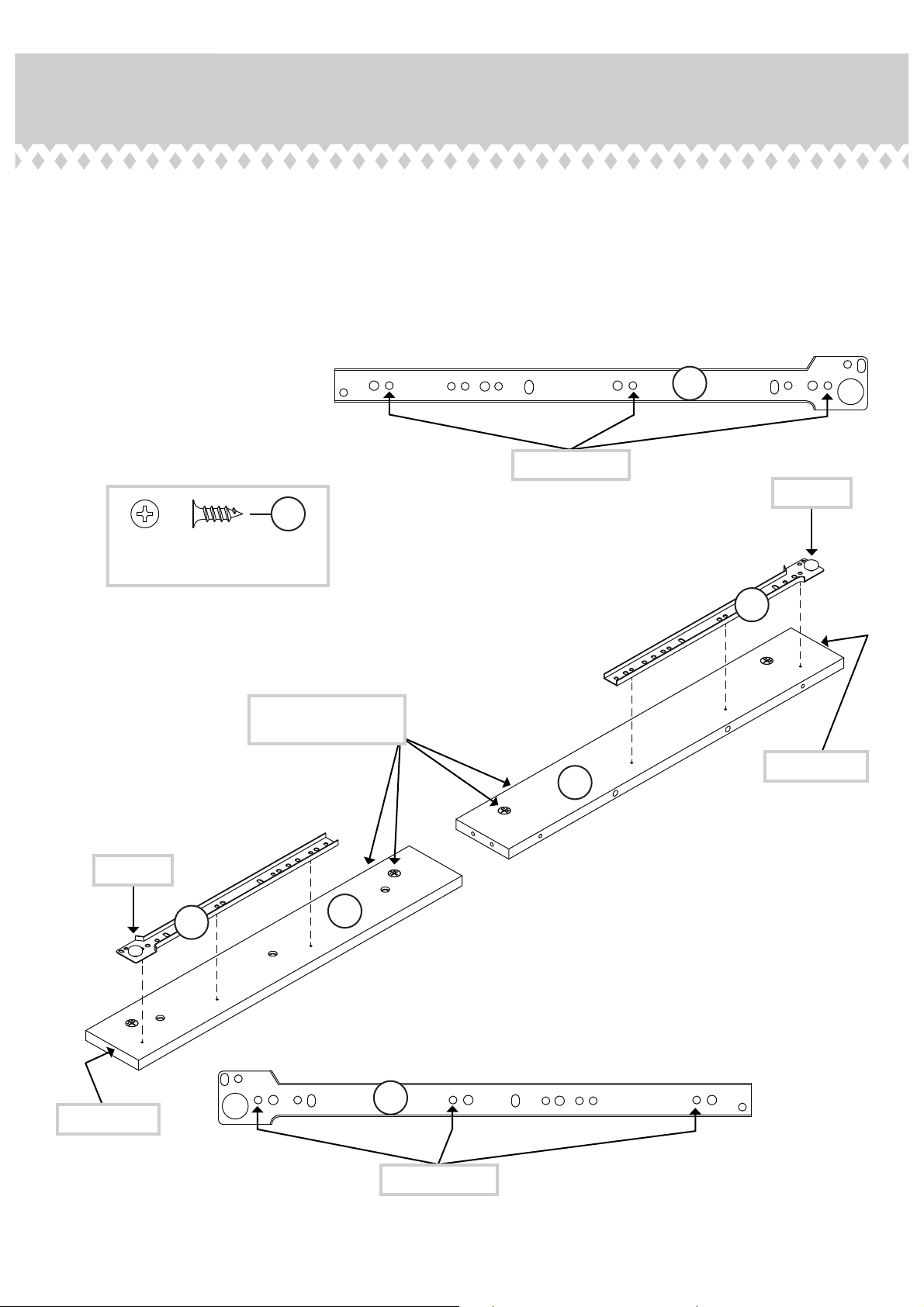
Step 2
Fasten the CABINET RIGHT (1) to the UPRIGHT (G). Use
å
three BLACK 1/2" FLAT HEAD SCREWS (28).
Fasten the CABINET LEFT (2) to the LEFT END (D). Use
å
three BLACK 1/2" FLAT HEAD SCREWS (28).
28
BLACK 1/2" FLAT HEAD SCREW
(6 used in this step)
1
Use these holes.
Roller end
Roller end
1
The HIDDEN CAMS
are closer to this edge.
Finished edge
G
2
D
Finished edge
2
Use these holes.
Page 7
Page 8
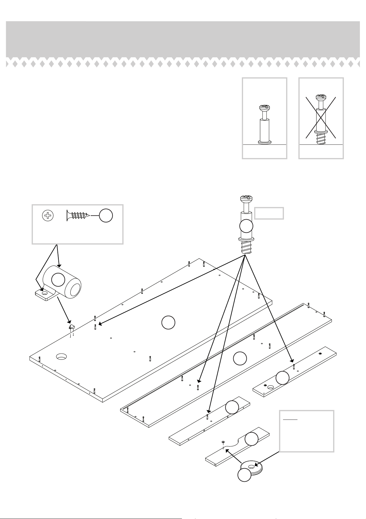
Step 3
Separate the WASHER from the MAGNETIC CATCH (11).
å
Fasten the MAGNETIC CATCH (11) to the DESK TOP (A) exactly as
å
shown. Use two BLACK 9/16" FLAT HEAD SCREWS (27).
Fasten the WASHER to the FLIP DOWN DOOR (F) exactly as
å
shown. Use one BLACK 9/16" FLAT HEAD SCREW (27).
Turn nineteen LARGE CAM SCREWS (6) into the exact holes
å
shown in the DESK TOP (A), UPRIGHT (G), RIGHT END (H), and
HUTCH TOP (L).
27
BLACK 9/16" FLAT HEAD SCREW
(3 used in this step)
11
(19 used)
6
A
L
H
Page 8
G
NOTE: Be sure the
larger hole is facing
up so the SCREW
F
11
will seat down into
the WASHER.
Page 9
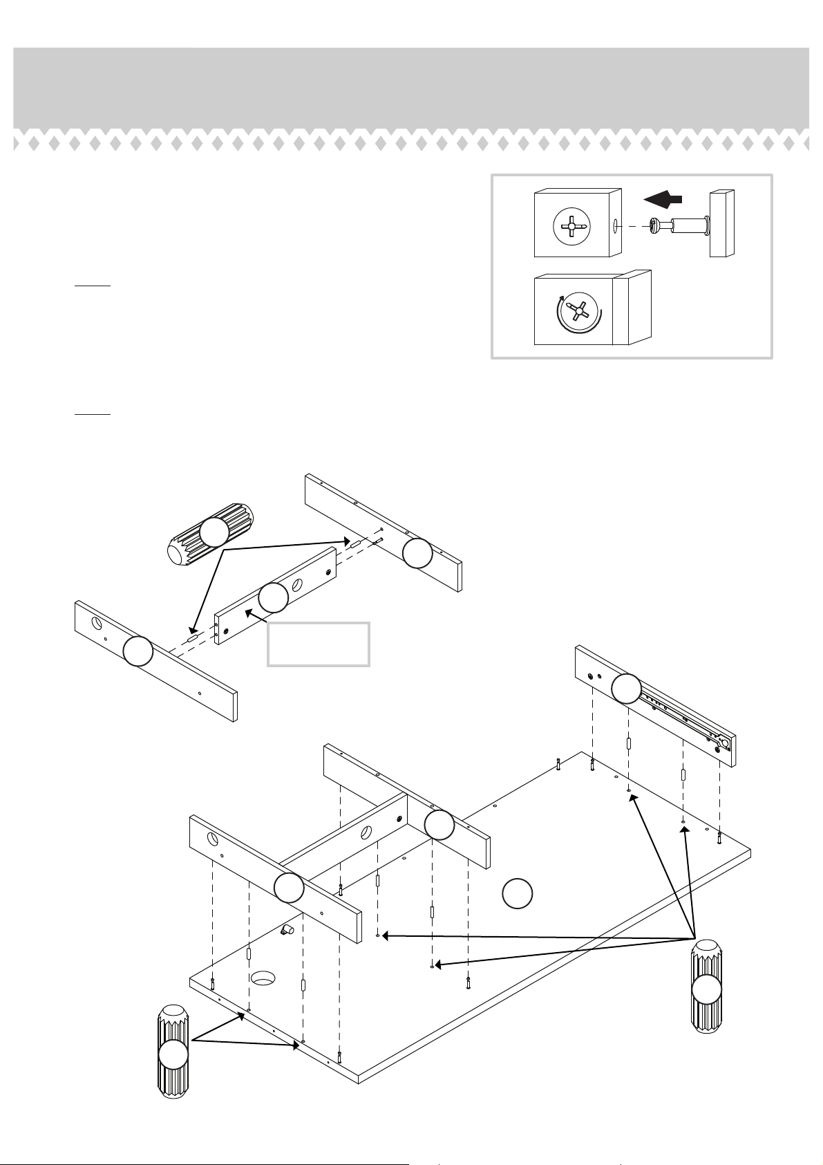
Step 4
Insert two WOOD DOWELS (9) into the UPRIGHT (G) and
å
RIGHT END (H).
Fasten the DIVIDER (EE) to the UPRIGHT (G) and RIGHT END (H).
å
Tighten two HIDDEN CAMS.
NOTE: Be sure the WOOD DOWELS in the UPRIGHT and RIGHT
å
END insert into the DIVIDER.
Insert six WOOD DOWELS (9) into the DESK TOP (A).
å
Fasten the ENDS (D and H) and UPRIGHT (G) to the DESK TOP (A).
å
Tighten six HIDDEN CAMS.
NOTE: Be sure the WOOD DOWELS in the DESK TOP insert into
å
the ENDS and UPRIGHT.
9
G
EE
1
2
Surface with
H
HIDDEN CAMS
H
D
G
A
9
9
Page 9
Page 10
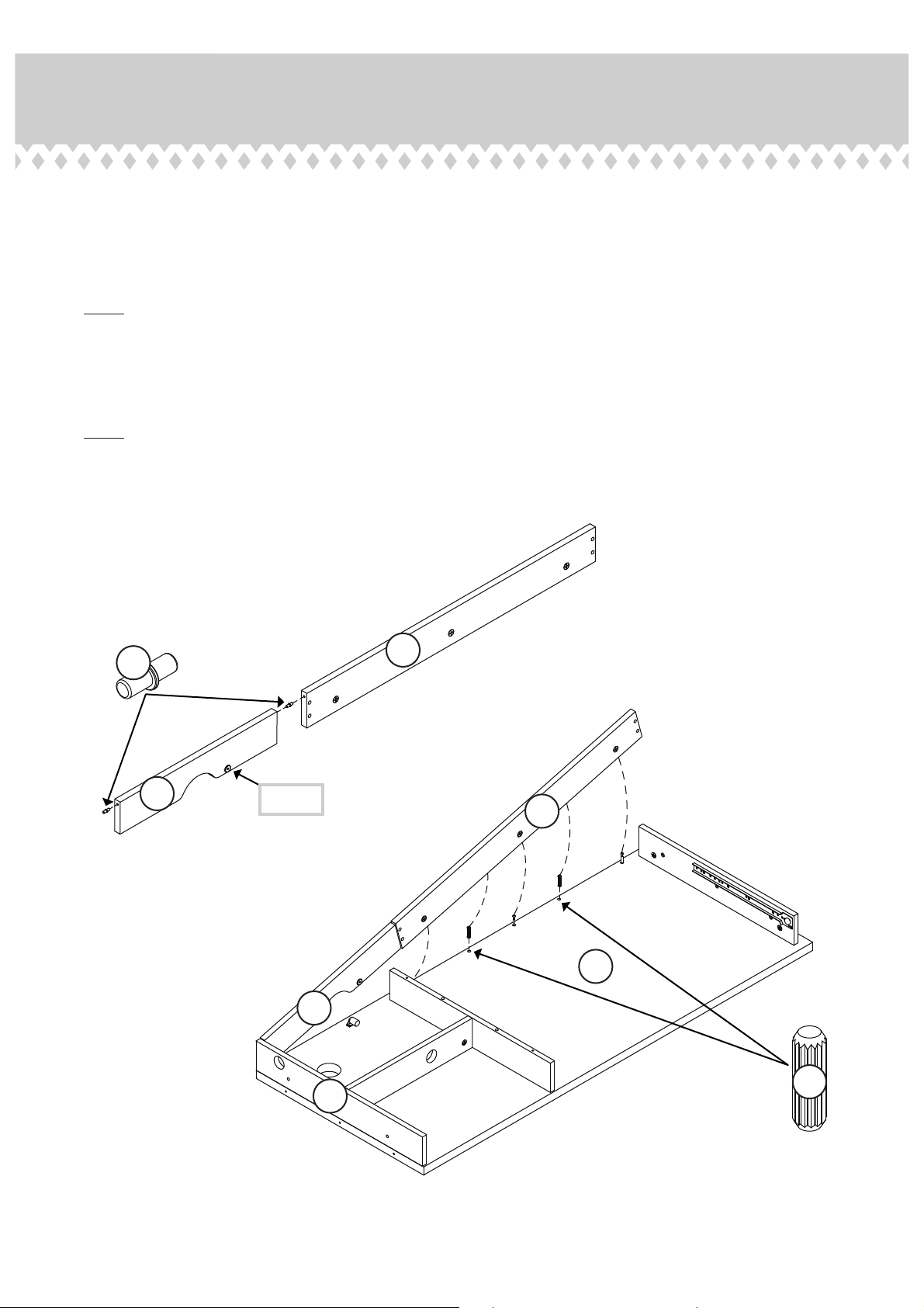
Step 5
Insert two WOOD DOWELS (9) into the DESK TOP (A).
å
Insert two METAL PINS (10) into the FLIP DOWN DOOR (F).
å
Place the REAR PANEL (E) onto one of the METAL PINS in the FLIP DOWN DOOR (F).
å
NOTE: Position the REAR PANEL (E) and FLIP DOWN DOOR (F) exactly as shown.
å
Insert the METAL PIN in the other end of the FLIP DOWN DOOR (F) into the RIGHT
å
END (H) keeping the REAR PANEL (E) connected to the FLIP DOWN DOOR (F).
Fasten the REAR PANEL (E) to the DESK TOP (A). Tighten three HIDDEN CAMS.
å
NOTE: Be sure the WOOD DOWELS in the DESK TOP insert into the REAR PANEL.
å
10
Surface with
HIDDEN CAMS
E
F
Washer
E
A
F
Page 10
H
9
Page 11
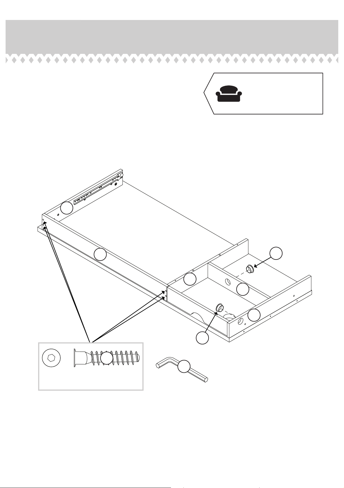
Step 6
Fasten the REAR PANEL (E) to the LEFT END (D) and
å
UPRIGHT (G). Tighten four BLACK 1-1/2" HEX HEAD
SCREWS (22) using the L-WRENCH (15).
Insert one of the GROMMETS (12) into the large hole in
å
the DIVIDER (EE).
Insert one GROMMET (12) into the large hole in the
å
RIGHT END (H).
Just think. The sooner
you do this, the sooner
you do something else.
D
E
22
BLACK 1-1/2" HEX HEAD SCREW
(4 used in this step)
12
G
EE
H
12
15
Page 11
Page 12
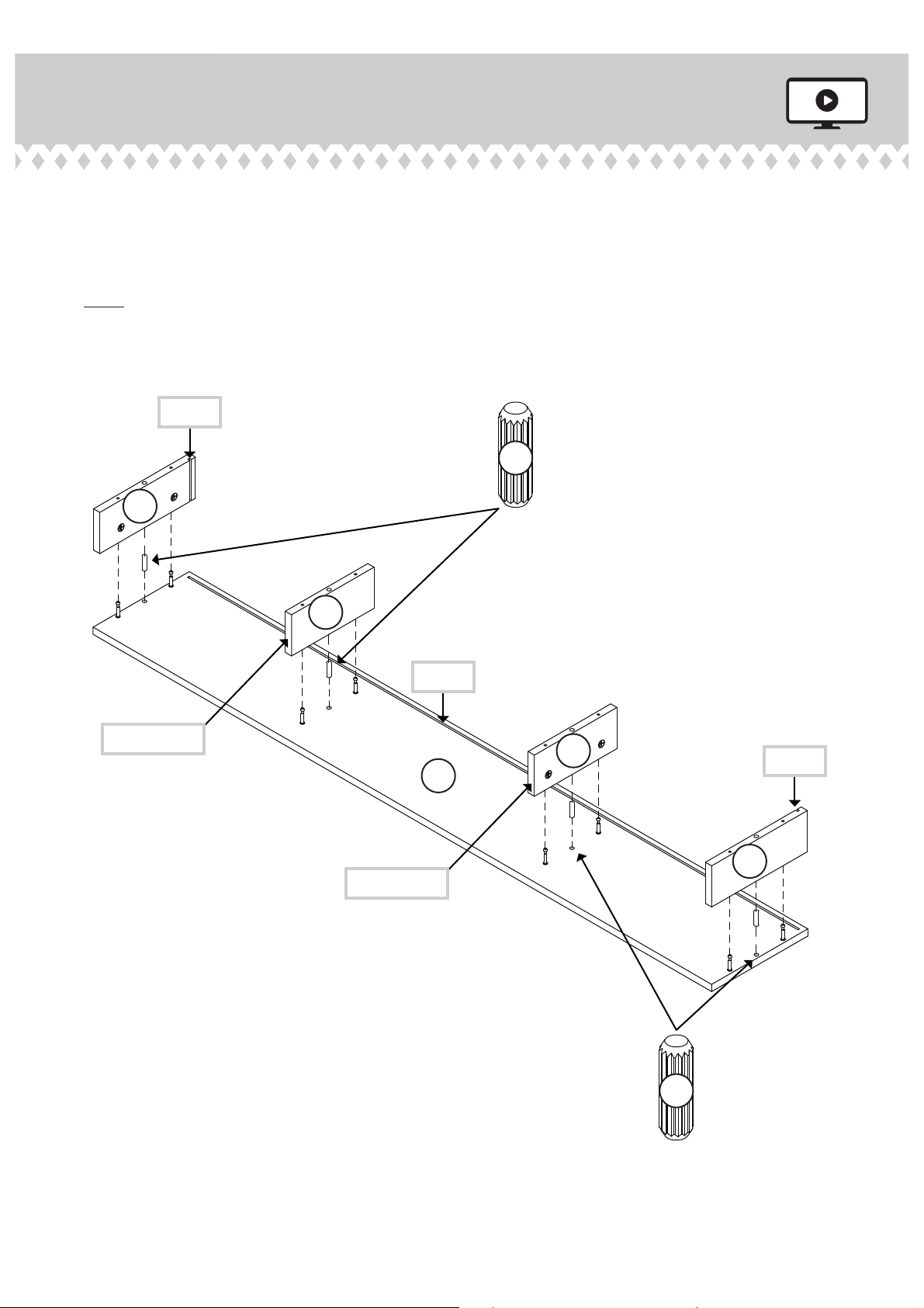
Step 7
Insert four WOOD DOWELS (9) into the HUTCH
å
TOP (L). Fasten the HUTCH ENDS (M and N) and
HUTCH UPRIGHTS (O and P) to the HUTCH TOP (L).
Tighten eight HIDDEN CAMS.
NOTE: Be sure the WOOD DOWELS in the HUTCH TOP
å
insert into the HUTCH ENDS and HUTCH UPRIGHTS.
Groove
N
9
Finished edge
P
Finished edge
Groove
L
O
Groove
M
Page 12
9
Page 13
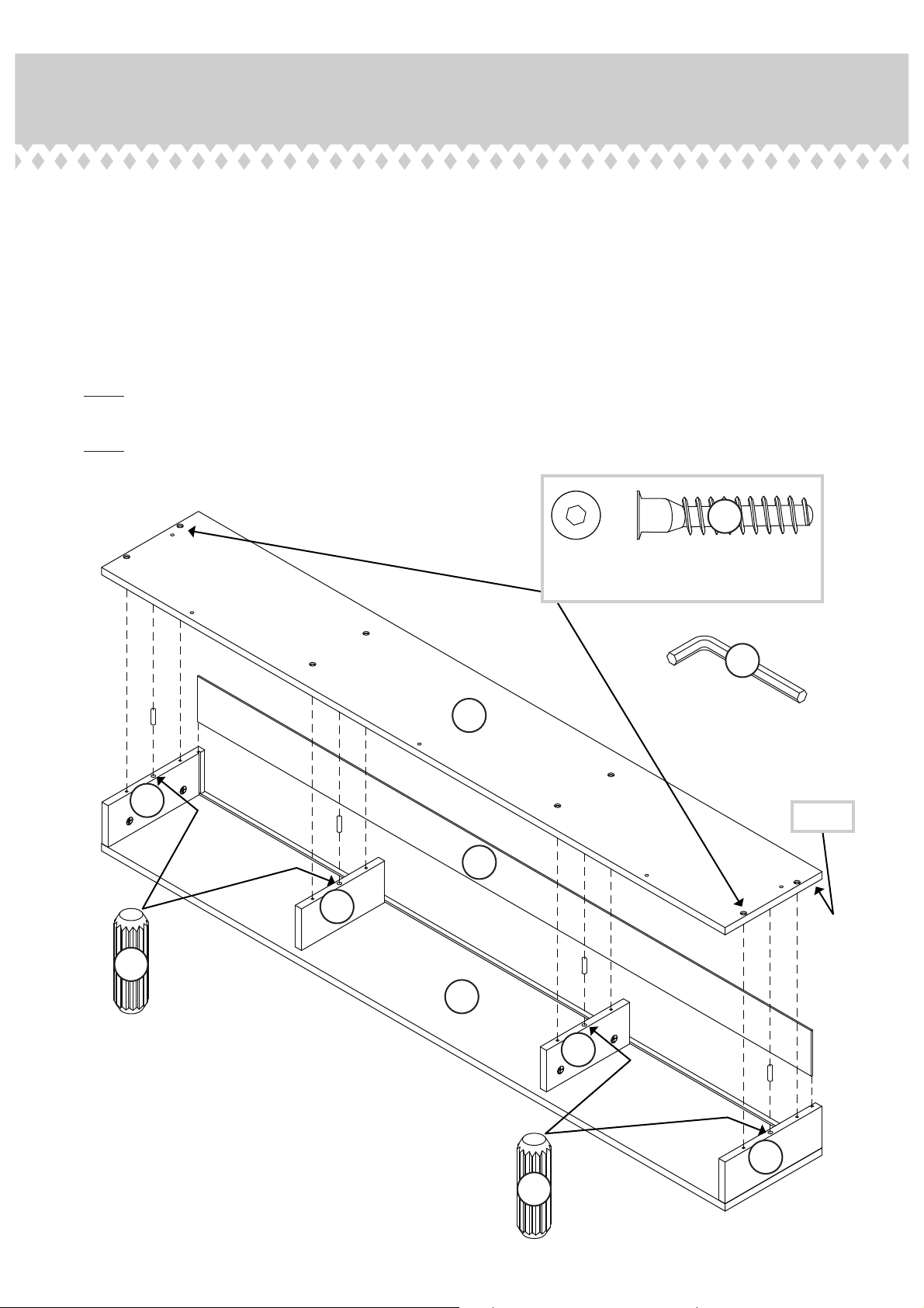
Step 8
Slide the HUTCH BACK (Q) down into the grooves in the HUTCH
å
TOP (L) and HUTCH ENDS (M and N).
Insert four WOOD DOWELS (9) into the HUTCH ENDS (M and N)
å
and HUTCH UPRIGHTS (O and P).
Fasten the HUTCH BOTTOM (K) to the HUTCH ENDS (M and N)
å
and HUTCH UPRIGHTS (O and P). Tighten eight BLACK 1-1/2"
HEX HEAD SCREWS (22) using the L-WRENCH (15).
NOTE: Be sure the WOOD DOWELS in the HUTCH ENDS and
å
HUTCH UPRIGHTS insert into the HUTCH BOTTOM.
NOTE: Be sure the HUTCH BACK inserts into the groove in the
å
HUTCH BOTTOM.
22
BLACK 1-1/2" HEX HEAD SCREW
(8 used in this step)
15
K
N
Groove
Q
P
9
L
O
M
9
Page 13
Page 14
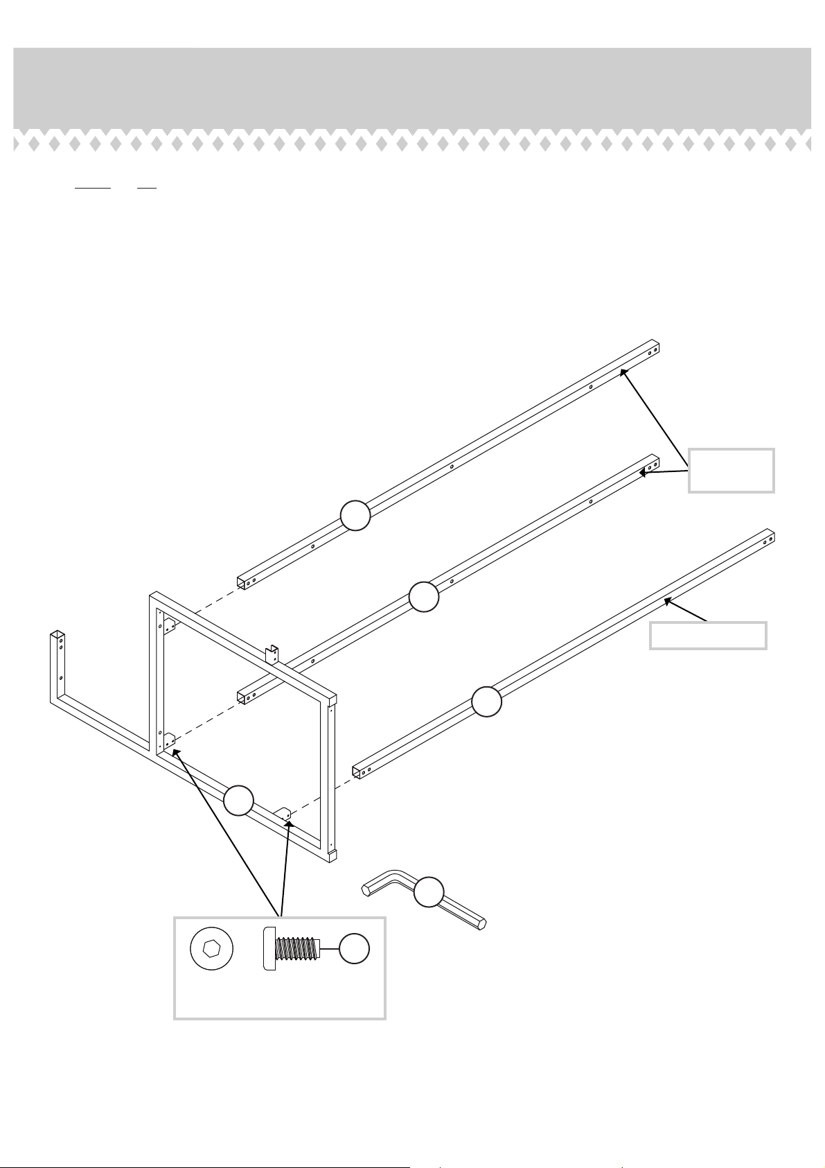
Step 9
NOTE: Do not completely tighten the SCREWS in this step.
å
Slide the MOLDINGS (AA and BB) onto the LEFT RETURN FRAME (Y).
å
Fasten the MOLDINGS (AA and BB) to the LEFT RETURN FRAME (Y). Tighten
å
six BLACK 7/16" HEX HEAD SCREWS (29) using the L-WRENCH (15).
Surface with
more holes
BB
BB
Surface with holes
AA
Y
15
Page 14
29
BLACK 7/16" HEX HEAD SCREW
(6 used in this step)
Page 15
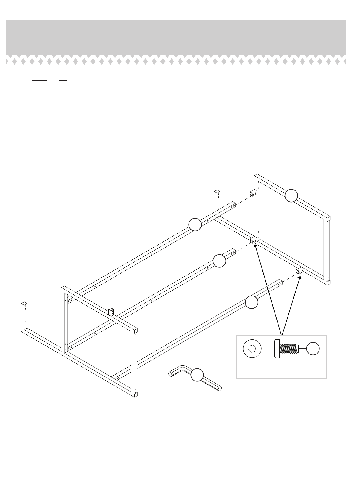
Step 10
NOTE: Do not completely tighten the SCREWS in this step.
å
Slide the RIGHT RETURN FRAME (X) into the MOLDINGS (AA and BB).
å
Fasten the RIGHT RETURN FRAME (X) to the MOLDINGS (AA and BB).
å
Tighten six BLACK 7/16" HEX HEAD SCREWS (29) using the L-WRENCH (15).
X
BB
15
BB
AA
29
BLACK 7/16" HEX HEAD SCREW
(6 used in this step)
Page 15
Page 16
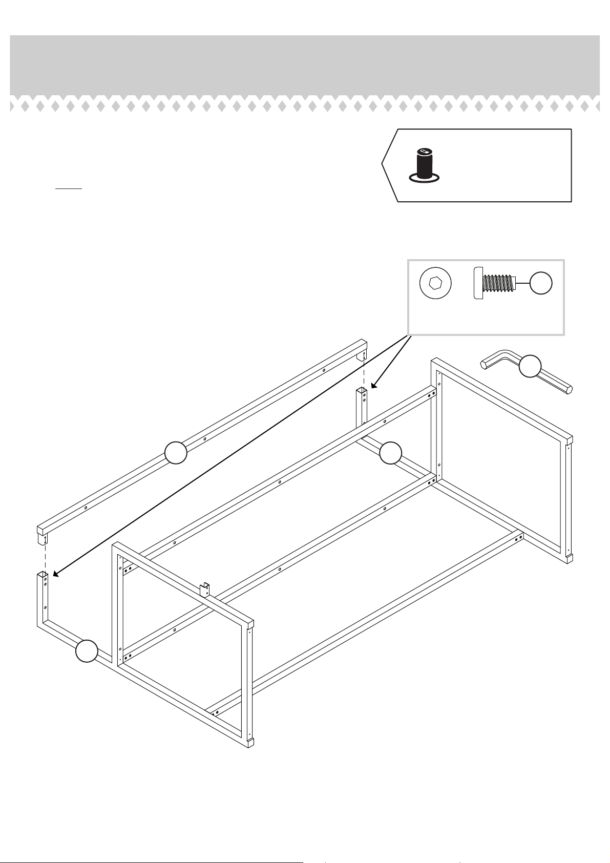
Step 11
Fasten the HUTCH MOLDING (CC) to the RETURN
å
FRAMES (X and Y). Tighten four BLACK 7/16" HEX
HEAD SCREWS (29) using the L-WRENCH (15).
NOTE: Position the HUTCH MOLDING (CC) exactly
å
as shown.
Completely tighten all of the SCREWS in the frame.
å
Now might be a
good time to refresh
your drink.
29
BLACK 7/16" HEX HEAD SCREW
(4 used in this step)
15
CC
Y
X
Page 16
Page 17
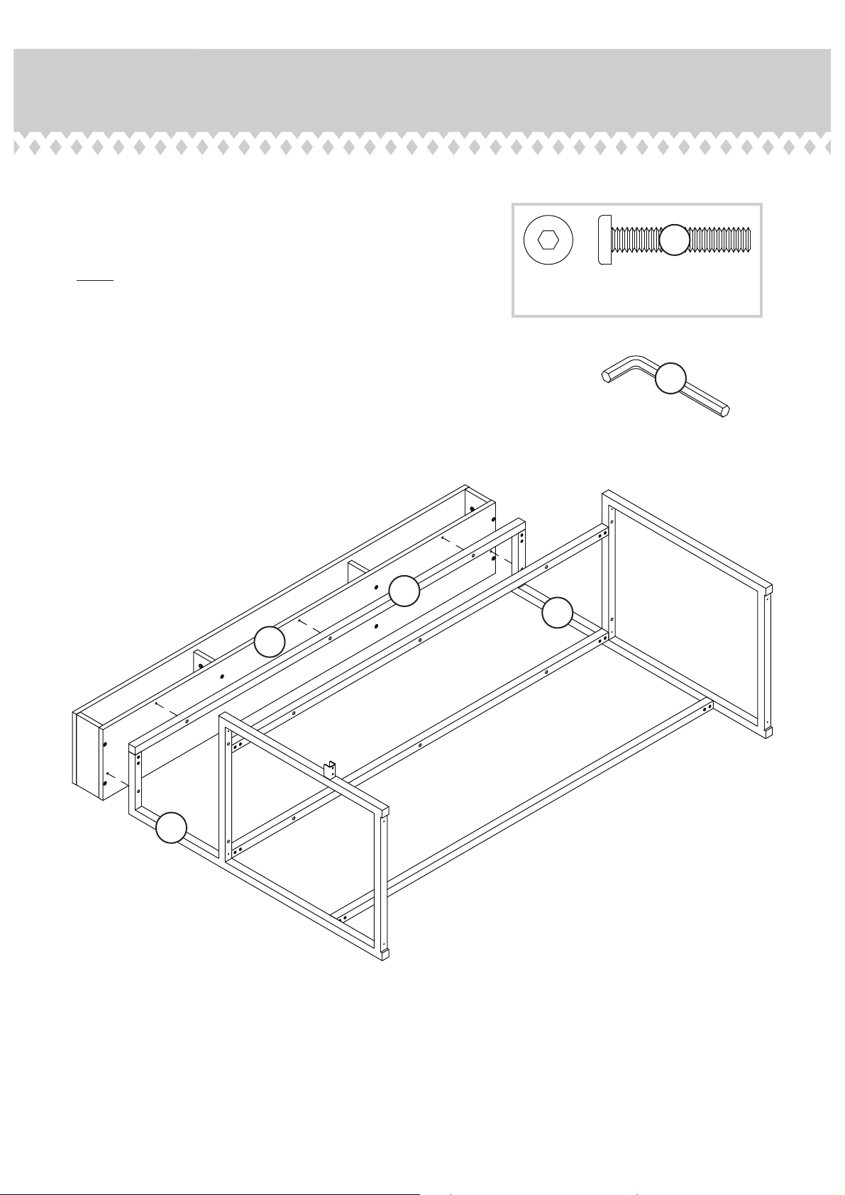
Step 12
Fasten the HUTCH BOTTOM (K) to the RETURN
å
FRAMES (X and Y) and HUTCH MOLDING (CC).
Tighten fi ve BLACK 1-3/8" HEX HEAD SCREWS (23)
using the L-WRENCH (15).
23
NOTE: Start each SCREW a few turns before
å
tightening any of them.
K
BLACK 1-3/8" HEX HEAD SCREW
(5 used in this step)
15
CC
X
Y
Page 17
Page 18
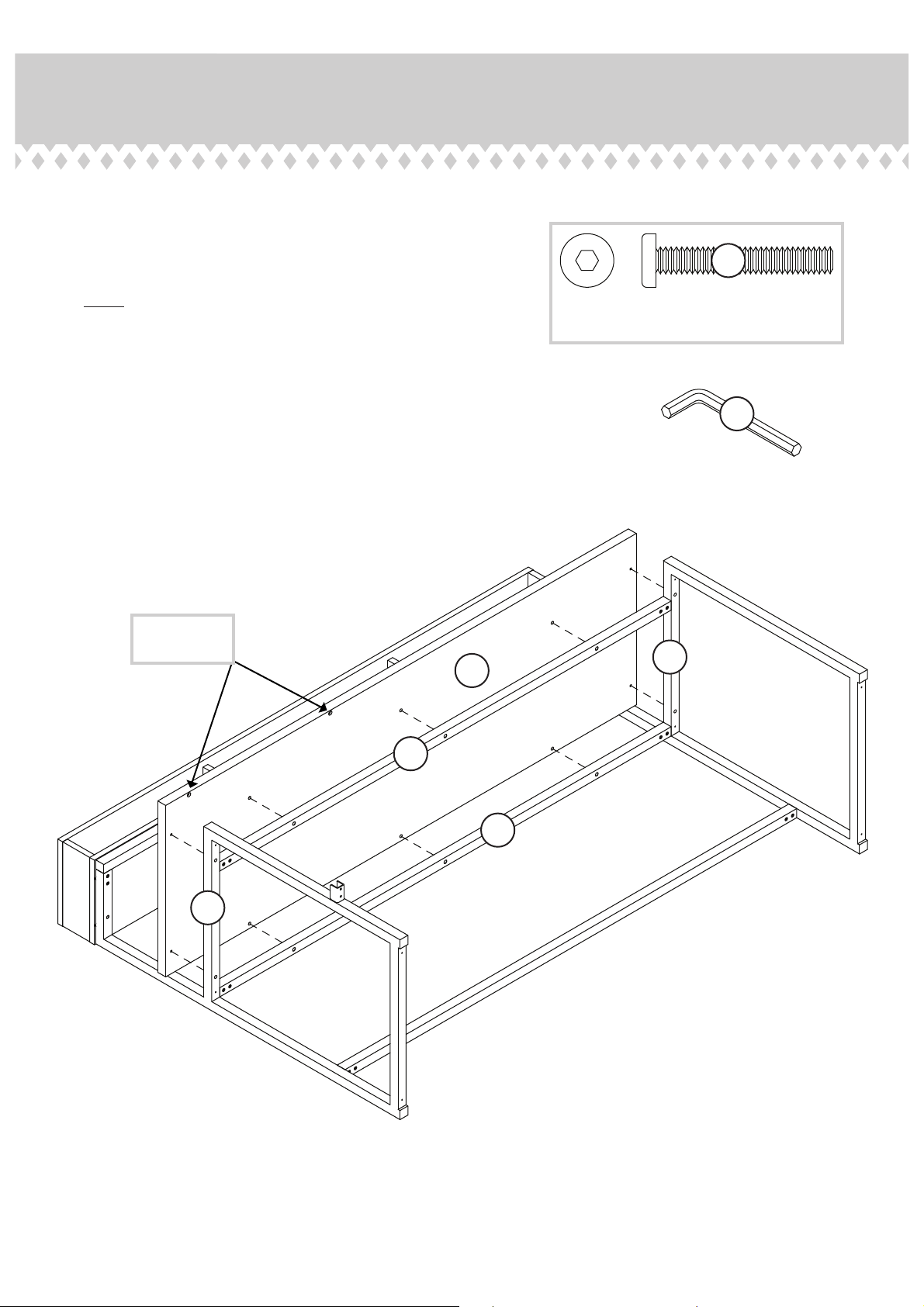
Step 13
Fasten the RETURN TOP (B) to the RETURN FRAMES (X
å
and Y) and UPPER RETURN MOLDINGS (BB). Tighten
ten BLACK 1-9/16" HEX HEAD SCREWS (21) using the
L-W RE N CH (1 5) .
21
NOTE: Start each SCREW a few turns before tightening any
å
of them.
These holes
must be here.
BLACK 1-9/16" HEX HEAD SCREW
(10 used in this step)
15
X
B
BB
BB
Y
Page 18
Page 19
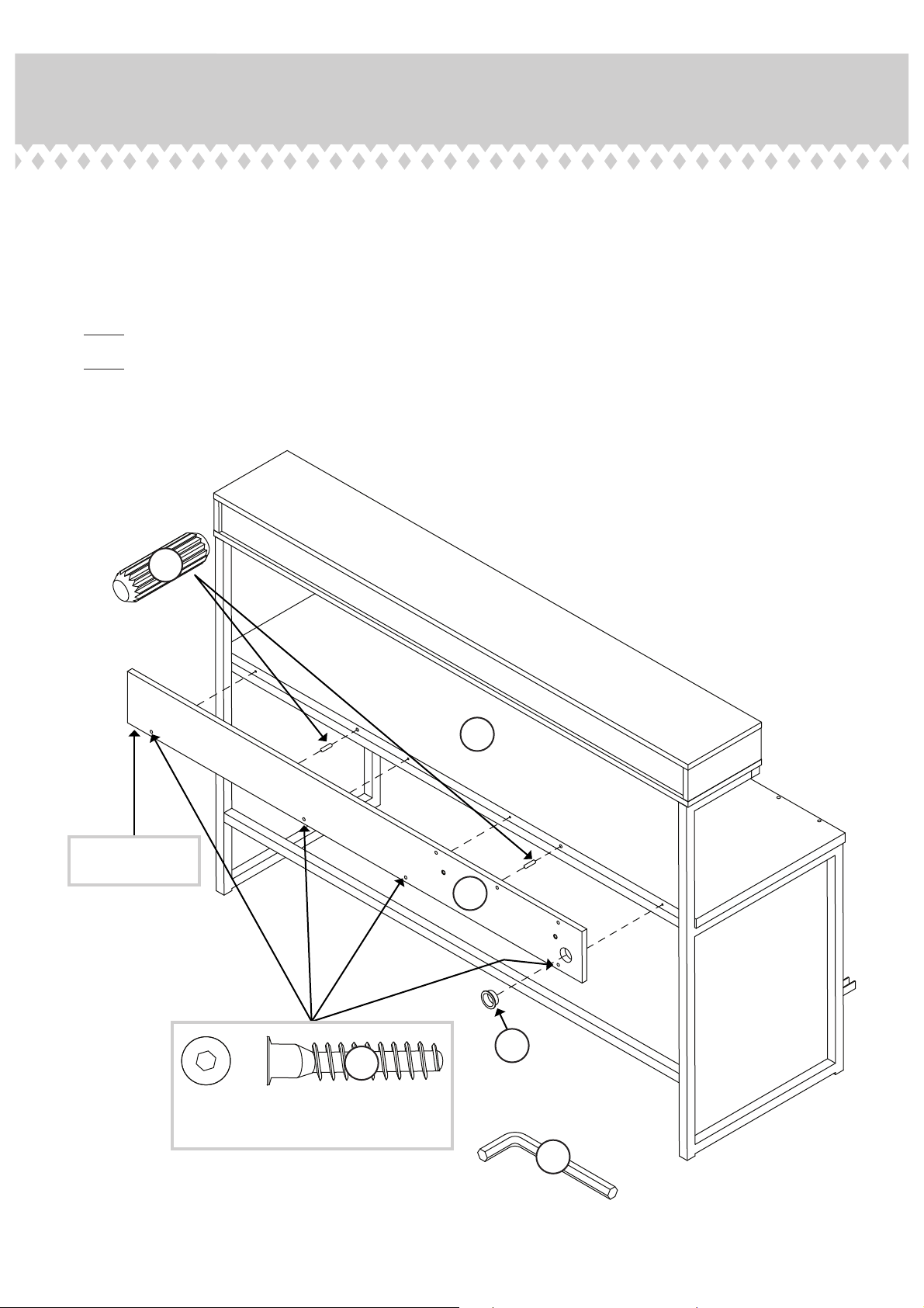
Step 14
With someone's help, carefully stand your unit upright.
å
Insert two WOOD DOWELS (9) into the RETURN BACK (J).
å
Fasten the RETURN BACK (J) to the RETURN TOP (B). Tighten four BLACK
å
1-1/2" HEX HEAD SCREWS (22) using the L-WRENCH (15).
NOTE: Start each SCREW a few turns before tightening any of them.
å
NOTE: Be sure the WOOD DOWELS in the RETURN BACK insert into the
å
RETURN TOP.
Insert one GROMMET (12) into the large hole in the RETURN BACK (J).
å
9
The holes are
closer to this edge.
B
Surface with
fewer holes
J
22
BLACK 1-1/2" HEX HEAD SCREW
(4 used in this step)
12
15
Page 19
Page 20
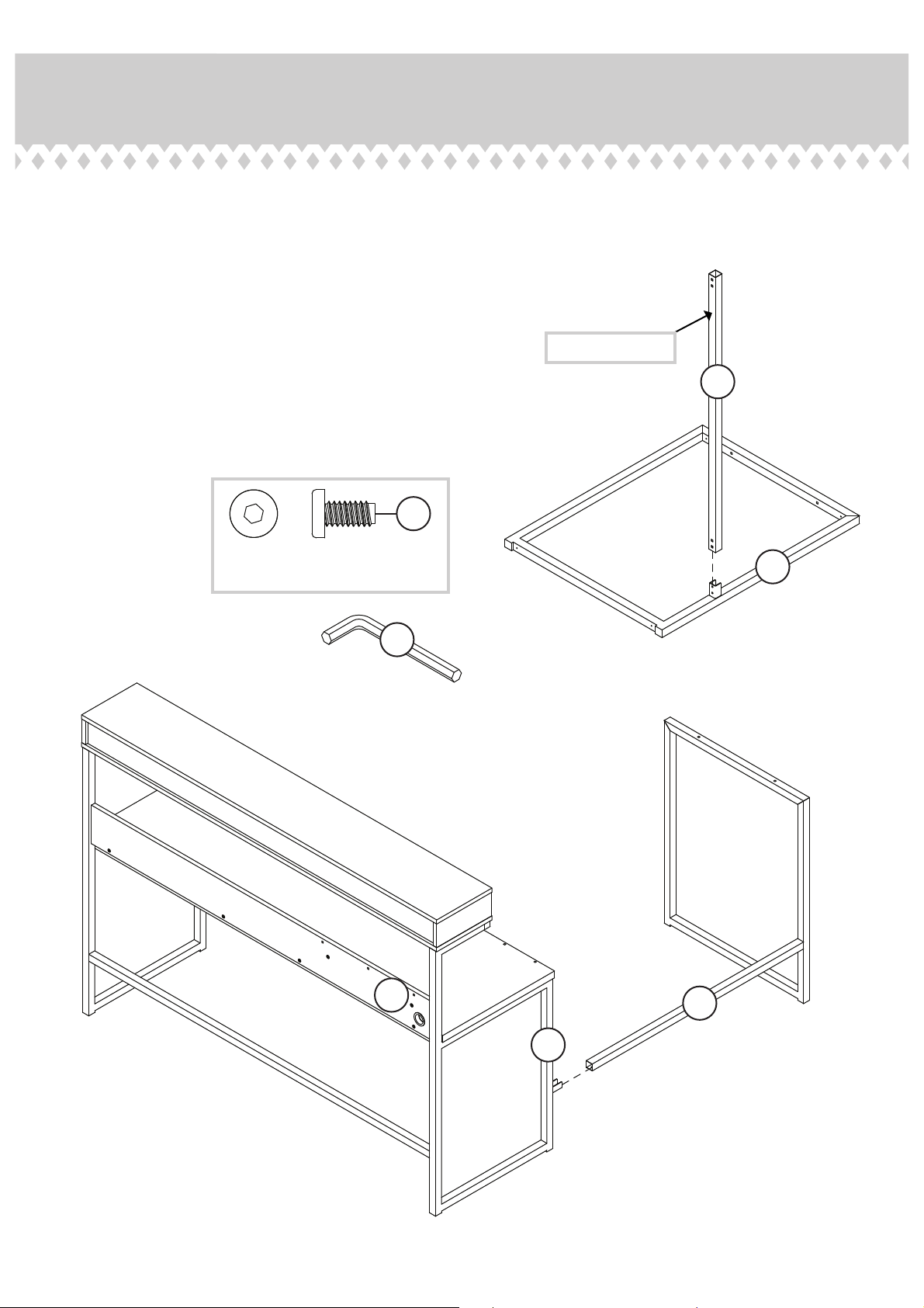
Step 15
Fasten the LOWER DESK MOLDING (DD) to the DESK
å
FRAME (Z). Tighten two BLACK 7/16" HEX HEAD
SCREWS (29) using the L-WRENCH (15).
Fasten the LOWER DESK MOLDING (DD) to the LEFT
å
RETURN FRAME (Y). Tighten two BLACK 7/16" HEX
HEAD SCREWS (29) using the L-WRENCH (15)
Surface with holes
DD
29
BLACK 7/16" HEX HEAD SCREW
(4 used in this step)
15
J
Z
DD
Page 20
Y
Page 21
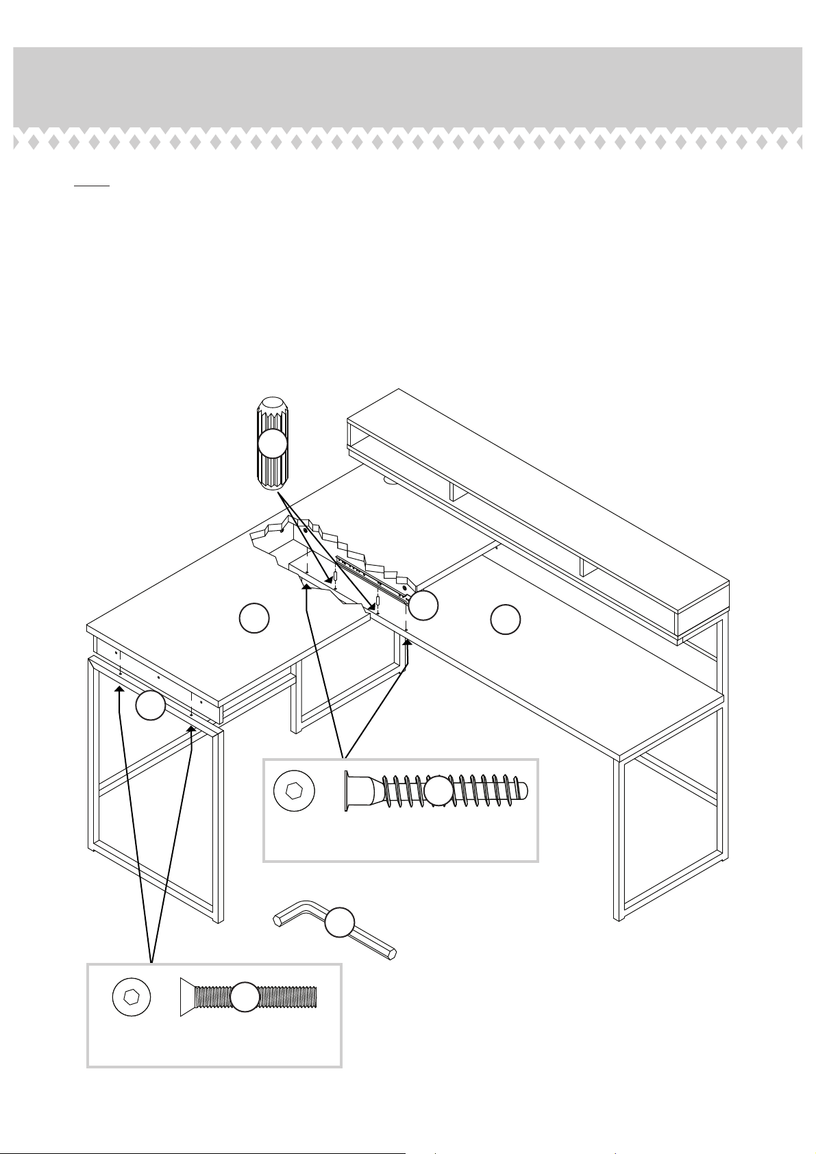
Step 16
NOTE: You may need someone's help in this step.
å
Insert two WOOD DOWELS (9) into the RETURN TOP (B).
å
Position the DESK TOP (A) into place so the UPRIGHT (G) sits down
å
onto the WOOD DOWELS in the RETURN TOP.
Fasten the UPRIGHT (G) to the RETURN TOP (B). Tighten two BLACK
å
1-7/8" HEX HEAD SCREWS (20) using the L-WRENCH (15).
Fasten the DESK TOP (A) to the DESK FRAME (Z). Tighten two BLACK
å
1-3/8" TAPERED MACHINE SCREWS (25) using the L-WRENCH (15).
9
A
Z
BLACK 1-7/8" HEX HEAD SCREW
(2 used for the UPRIGHT)
15
25
G
B
20
BLACK 1-3/8" TAPERED MACHINE SCREW
(2 used for the DESK FRAME)
Page 21
Page 22
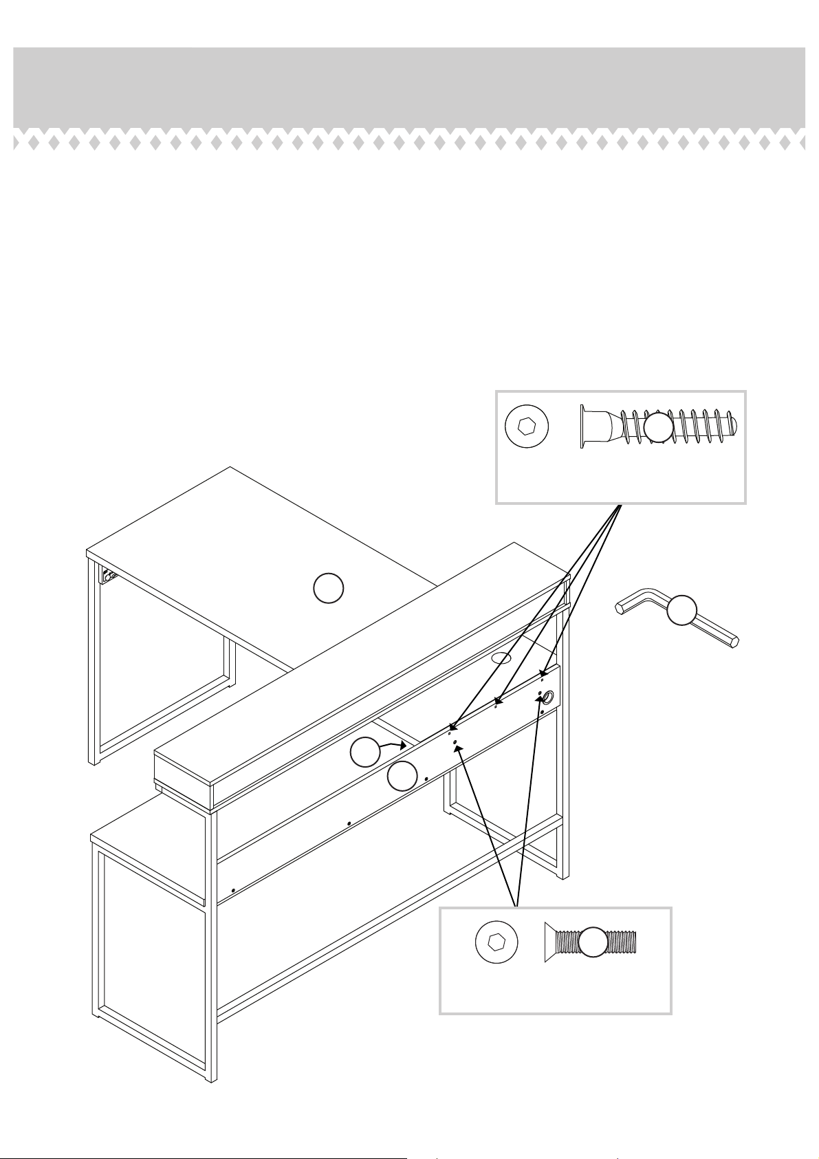
Step 17
Fasten the RETURN BACK (J) to the DESK TOP (A).
å
Tighten three BLACK 1-1/2" HEX HEAD SCREWS (22)
using the L-WRENCH (15).
Fasten the RETURN BACK (J) to the RIGHT END (H).
å
Tighten two BLACK 1" TAPERED MACHINE SCREWS (26)
using the L-WRENCH (15).
22
BLACK 1-1/2" HEX HEAD SCREW
(3 used in this step)
A
15
H
J
26
BLACK 1" TAPERED MACHINE SCREW
(2 used in this step)
Page 22
Page 23
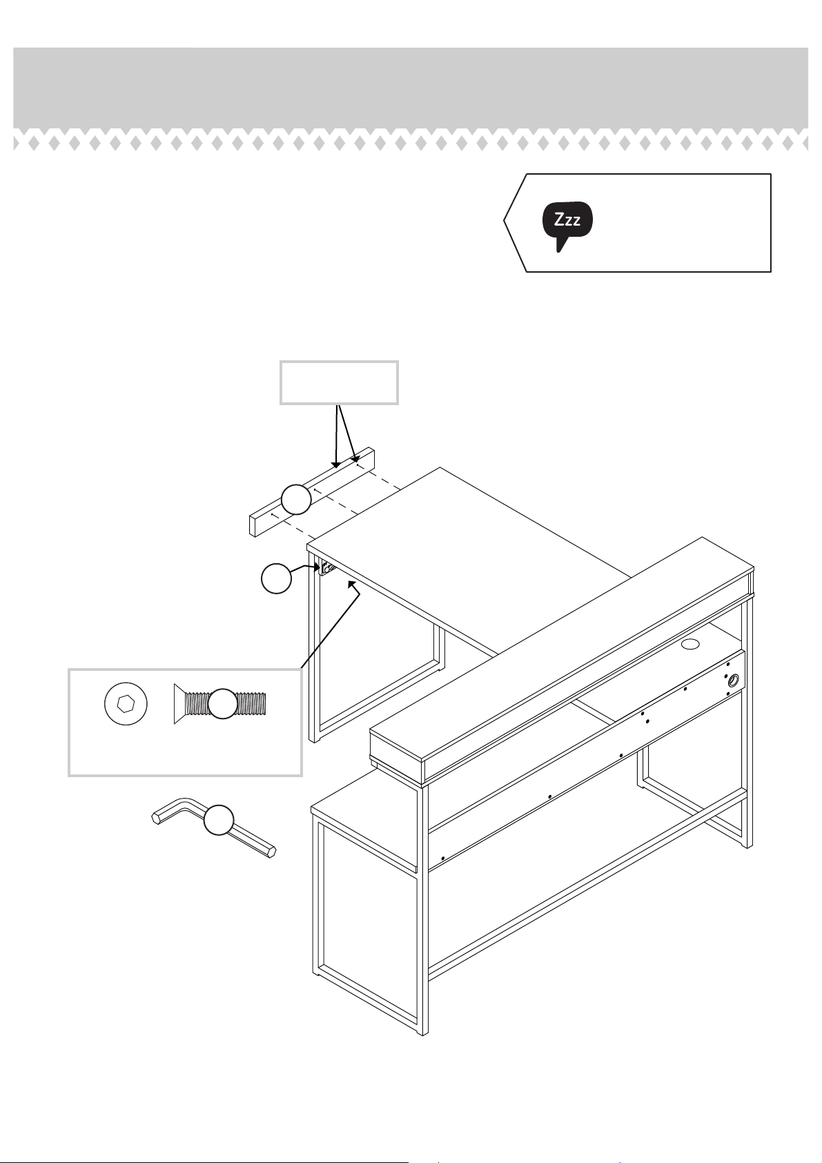
Step 18
Fasten the END MOLDING (C) to the LEFT END (D). Tighten
å
three BLACK 1" TAPERED MACHINE SCREWS (26) using
the L-WRENCH (15).
The holes are
closer to this edge.
Almost time to
celebrate! With a nap.
D
26
BLACK 1" TAPERED MACHINE SCREW
(3 used in this step)
15
C
Page 23
Page 24
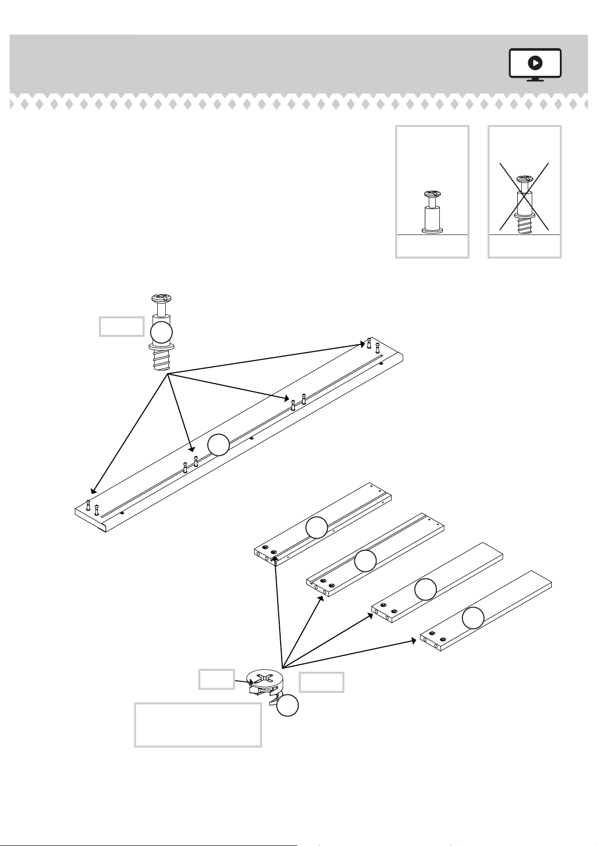
Step 19
Turn eight SMALL CAM SCREWS (8) into
å
the DRAWER FRONT (R).
Push eight SMALL HIDDEN CAMS (7)
å
into the DRAWER SIDES (S and T) and
DRAWER BRACES (W).
(8 used)
8
R
S
T
W
Page 24
Arrow
The arrow in the HIDDEN
CAM must point toward the
hole in the edge of the board.
W
(8 used)
7
Page 25
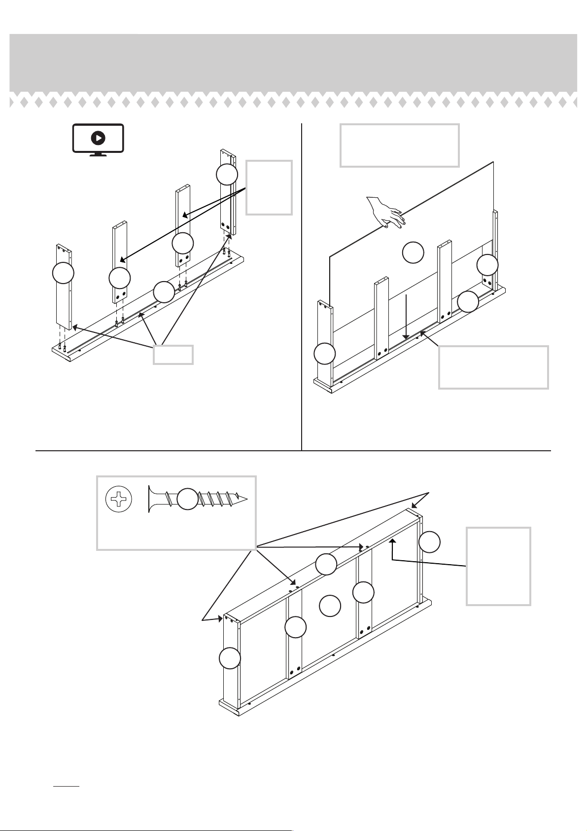
Step 20
12
Surface
S
with
HIDDEN
CAMS
With the palm of your hand,
tap the DRAWER BOTTOM
down into the groove.
W
V
S
T
W
R
R
Groove
Fasten the DRAWER SIDES (S and T) and DRAWER
å
BRACES (W) to the DRAWER FRONT (R). Tighten eight
HIDDEN CAMS.
T
Slide the DRAWER BOTTOM (V) into the grooves in the
å
DRAWER SIDES (S and T) and DRAWER FRONT (R).
Be sure the DRAWER
BOTTOM inserts into the
DRAWER FRONT groove.
3
24
BLACK 1-3/8" FLAT HEAD SCREW
(8 used in this step)
S
U
W
V
W
T
Fasten the DRAWER BACK (U) to the DRAWER SIDES (S and T) and DRAWER BRACES (W). Use eight BLACK 1-3/8"
å
FLAT HEAD SCREWS (24).
Be sure the
DRAWER
BOTTOM
inserts into
the DRAWER
BACK groove.
NOTE: Be sure the DRAWER BOTTOM (
å
V) inserts into the groove of the DRAWER BACK (U).
Page 25
Page 26
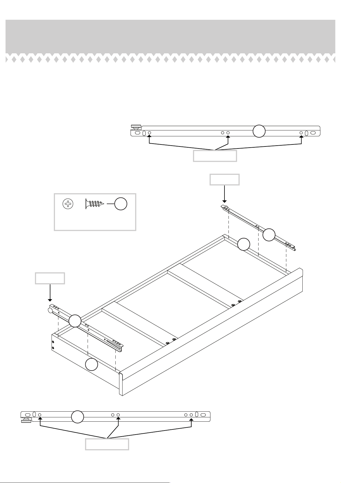
Step 21
Fasten the DRAWER RIGHT (3) to the RIGHT DRAWER SIDE (T).
å
Use three BLACK 1/2" FLAT HEAD SCREWS (28).
Fasten the DRAWER LEFT (4) to the LEFT DRAWER SIDE (S). Use
å
three BLACK 1/2" FLAT HEAD SCREWS (28).
28
4
Use these holes.
Roller end
Roller end
BLACK 1/2" FLAT HEAD SCREW
(6 used in this step)
4
S
3
T
Page 26
3
Use these holes.
Page 27
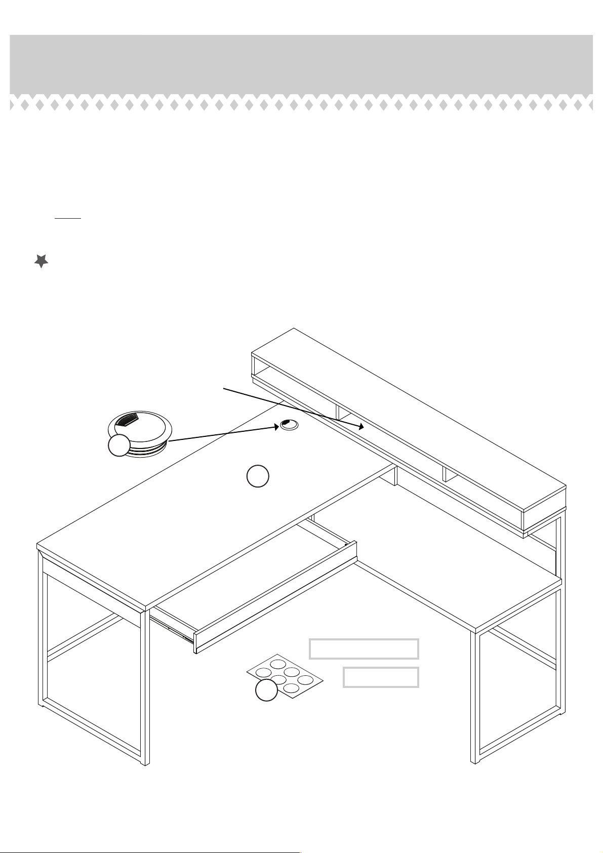
Step 22
Insert the GROMMET WITH CAP (14) into the large hole in the DESK TOP (A).
å
To insert the drawer into your unit, tip the front of the drawer down and drop the rollers on the drawer behind the
å
rollers on the unit. Lift the front of the drawer up and slide it into the unit.
Peel APPLIQUES from the APPLIQUE CARD (13) and stick them onto each visible HIDDEN CAM / SCREW head.
å
NOTE: Please read the back pages of the instruction booklet for important safety information.
å
This completes assembly. Clean with a damp cloth. Wipe dry.
å
And to celebrate
14
, why not share your success story?
25 lbs.
total
15 lbs.
A
60 lbs.
50 lbs.
15 lbs.
To cover HIDDEN CAMS
To cover screws
13
Page 27
Page 28
Utilisez les instructions d’assemblage en français avec les
schémas étape par étape du manuel d’instruction en anglais.
Chaque étape en français correspond à la même étape
en anglais. La pièce devant être attachée à l’élément est
représentée en gris sur les schémas de chaque étape pour plus
de précision. Comparer la “Liste de pièces” ci-dessous avec
la “PART IDENTIFICATION” du manuel en anglais pour vous
familiariser avec les pièces avant l’assemblage.
REMARQUE : CE MANUEL D’INSTRUCTIONS CONTIENT
D’IMPORTANTES INFORMATIONS RELATIVES À LA SÉCURITÉ.
À LIRE ET CONSERVER POUR TOUTE RÉFÉRENCE FUTURE.
NOUS SOMMES LA POUR VOUS AIDER!
Nous faisons de notre mieux pour nous assurer que votre meuble
arrive dans d’excellentes conditions. Nos représentants du service
Clientèle sont aimables et prêts à vous aider au cas où une pièce
aurait été endommagée ou manquerait (ou si vous aviez besoin
d’aide pour l’assemblage).
(sauf jours fériés)
Si une pièce a besoin d’être remplacée, la pièce de remplacement
sera envoyée dans les 48 heures. (Sauf week-ends et jours fériés)
LISTE DE PIÈCES
REFERENCE DESCRIPTION QUANTITÉ
A DESSUS DE BUREAU ...............................................1
B DESSUS DE RETOUR ...............................................1
C MOULURE D’EXTRÉMITÉ ......................................1
D EXTRÉMITÉ GAUCHE ...............................................1
E PANNEAU ARRIÈRE ....................................................1
F PORTE RABATTANTE ...............................................1
G MONTANT..........................................................................1
H EXTRÉMITÉ DROITE ..................................................1
J ARRIÈRE DE RETOUR ...............................................1
K DESSOUS DE SURMEUBLE ................................1
L DESSUS DE SURMEUBLE .....................................1
M EXTRÉMITÉ DE SURMEUBLE GAUCHE ....1
N EXTRÉMITÉ DE SURMEUBLE DROITE ........1
O MONTANT GAUCHE DE SURMEUBLE .......1
P MONTANT DROIT DE SURMEUBLE .............1
Q ARRIÈRE DE SURMEUBLE ....................................1
R DEVANT DE TIROIR ....................................................1
S CÔTÉ GAUCHE DE TIROIR ..................................1
T CÔTÉ DROIT DE TIROIR ........................................1
U ARRIÈRE DE TIROIR ...................................................1
V FOND DE TIROIR ..........................................................1
W ENTRETOISE DE TIROIR .......................................2
X CADRE DE RETOUR DROIT .................................1
Y CADRE DE RETOUR GAUCHE ..........................1
Z CADRE DE BUREAU ...................................................1
AA MOULURE DE RETOUR INFÉRIEUR..............1
BB MOULURE DE RETOUR SUPÉRIEUR ..........2
CC MOULURE DE SURMEUBLE ...............................1
DD MOULURE DE BUREAU INFÉRIEUR .............1
EE SÉPARATEUR ..................................................................1
LISTE DE PIÈCES
REFERENCE DESCRIPTION QUANTITÉ
1 ÉLÉMENT DROITE.......................................................1
2 ÉLÉMENT GAUCHE ...................................................1
3 TIROIR DROIT .................................................................1
4 TIROIR GAUCHE ...........................................................1
5 GRANDE EXCENTRIQUE ESCAMOTABLE ......19
6 GRANDE VIS D'EXCENTRIQUE ..................... 19
7 PETITE EXCENTRIQUE ESCAMOTABLE .8
8 PETITE VIS D'EXCENTRIQUE ............................8
9 CHEVILLE EN BOIS ............................................... 22
10 GOUPILLE EN MÉTAL .............................................2
11 LOQUETEAU MAGNÉTIQUE ..............................1
12 PASSE-CÂBLES ...........................................................3
13 FICHE D'APPLIQUÉS ...............................................6
14 PASSE-CÂBLES AVEC COUVERCLE ..........1
15 CLÉ EN L .............................................................................1
20 VIS TÊTE HEX 48 mm NOIRE...........................2
21 VIS TÊTE HEX 40 mm NOIRE .......................10
22 VIS TÊTE HEX 38 mm NOIRE........................ 19
23 VIS TÊTE HEX 35 mm NOIRE...........................5
24 VIS TÊTE PLATE 35 mm NOIRE .....................8
25 VIS À MÉTAUX EFFILÉ 35 mm NOIRE ......2
26 VIS À MÉTAUX EFFILÉ 25 mm NOIRE ......5
27 VIS TÊTE PLATE 14 mm NOIRE ......................3
28 VIS TÊTE PLATE 13 mm NOIRE ....................12
29 VIS TÊTE HEX 11 mm NOIRE .........................20
Page 28
Page 29
ÉTAPE 1
Assembler l'élément sur un sol à moquette ou sur le carton vide
pour éviter d'endommager l'élément ou le sol.
Enfoncer dix-neuf GRANDES EXCENTRIQUES ESCAMOTABLES (5)
dans l'EXTRÉMITÉ GAUCHE (D), le PANNEAU ARRIÈRE (E), le
MONTANT (G), l'EXTRÉMITÉ DROITE (H), les EXTRÉMITÉS DE
SURMEUBLE (M et N), les MONTANTS DE SURMEUBLE (O et P) et
le SÉPARATEUR (EE).
ÉTAPE 2
Fixer l'ÉLÉMENT DROITE (1) au MONTANT (G). Utiliser trois VIS
TÊTE PLATE 13 mm NOIRES (28).
Fixer l'ÉLÉMENT GAUCHE (2) à l'EXTRÉMITÉ GAUCHE (D).
Utiliser trois VIS TÊTE PLATE 13 mm NOIRES (28).
ÉTAPE 3
Séparer la RONDELLE du LOQUETEAU MAGNÉTIQUE (11).
Fixer le LOQUETEAU MAGNÉTIQUE (11) au DESSUS DE
BUREAU (A) exactement comme il l’est indiqué. Utiliser deux VIS
TÊTE PLATE 14 mm NOIRES (27).
Fixer la RONDELLE à la PORTE RABATTANTE (F) exactement
comme l'indique le schéma. Utiliser une VIS TÊTE
PLATE 14 mm NOIRES (27).
Faire tourner dix-neuf GRANDES VIS D'EXCENTRIQUE (6) dans
les trous exacts illustrés dans le DESSUS DU BUREAU (A), le
MONTANT (G), l'EXTRÉMITÉ DROITE (H) et le DESSUS
DE SURMEUBLE (L).
ÉTAPE 4
Insérer deux CHEVILLES EN BOIS (9) dans le MONTANT (G) et
l’EXTRÉMITÉ DROITE (H).
Fixer le SÉPARATEUR (EE) au MONTANT (G) et à l'EXTRÉMITÉ
DROITE (H). Serrer deux EXCENTRIQUES ESCAMOTABLES.
REMARQUE : S’assurer d’insérer les CHEVILLES EN BOIS du
MONTANT et l’EXTRÉMITÉ DROITE dans le SÉPARATEUR.
Insérer six CHEVILLES EN BOIS (9) dans le DESSUS DE BUREAU (A).
Fixer les EXTRÉMITÉS (D et H) et le MONTANT (G) au DESSUS
DE BUREAU (A). Serrer six EXCENTRIQUES ESCAMOTABLES.
REMARQUE : S’assurer de bien insérer les CHEVILLES EN BOIS
du DESSUS DE BUREAU dans les EXTRÉMITÉS et le MONTANT.
ÉTAPE 5
Insérer deux CHEVILLES EN BOIS (9) dans le DESSUS
DE BUREAU (A).
Insérer deux GOUPILLES EN MÉTAL (10) dans la
PORTE RABATTANTE (F).
Placer le PANNEAU ARRIÈRE (E) sur l’une des GOUPILLES EN
MÉTAL dans la PORTE RABATTANTE (F).
REMARQUE : Placer le PANNEAU ARRIÈRE (E) et la PORTE
RABATTANTE (F) exactement comme l'indique le schéma.
Insérer la GOUPILLE EN MÉTAL dans l'autre extrémité de
la PORTE RABATTANTE (F) dans l'EXTRÉMITÉ DROITE (H)
en gardant le PANNEAU ARRIÈRE (E) connecté à la PORTE
RABATTANTE (F).
Fixer le PANNEAU ARRIÈRE (E) au DESSUS DE BUREAU (A).
Serrer trois EXCENTRIQUES ESCAMOTABLES.
REMARQUE : S’assurer de bien insérer les CHEVILLES EN BOIS
du DESSUS DE BUREAU dans le PANNEAU ARRIÈRE.
ÉTAPE 6
Fixer le PANNEAU ARRIÈRE (E) à l'EXTRÉMITÉ GAUCHE (D) et au
MONTANT (G). Serrer quatre VIS TÊTE HEX 38 mm NOIRES (22)
avec la CLÉ EN L (15).
Insérer l’un des PASSE-CÂBLES (12) dans le gros trou
du SÉPARATEUR (EE).
Insérer un PASSE-CÂBLES (12) dans le gros trou dans
l’EXTRÉMITÉ DROITE (H).
ÉTAPE 7
Insérer quatre CHEVILLES EN BOIS (9) dans le DESSUS DE
SURMEUBLE (L). Fixer les EXTRÉMITÉS DE SURMEUBLE (M et N) et les
MONTANTS DE SURMEUBLE (O et P) au DESSUS DE SURMEUBLE (L).
Serrer huit EXCENTRIQUES ESCAMOTABLES.
REMARQUE : S’assurer de bien insérer les CHEVILLES EN
BOIS du DESSUS DE SURMEUBLE dans les EXTRÉMITÉS DE
SURMEUBLE et les MONTANTS DE SURMEUBLE.
ÉTAPE 8
Enfi ler l'ARRIÈRE DE SURMEUBLE (Q) dans les rainures
du DESSUS DE SURMEUBLE (L) et des EXTRÉMITÉS
DE SURMEUBLE (M et N).
Insérer quatre CHEVILLES EN BOIS (9) dans les EXTRÉMITÉS DE
SURMEUBLE (M et N) et les MONTANTS DE SURMEUBLE (O et P).
Fixer le DESSOUS DE SURMEUBLE (K) aux EXTRÉMITÉS DE
SURMEUBLE (M et N) et aux MONTANTS DE SURMEUBLE (O et P).
Serrer huit VIS TÊTE HEX 38 mm NOIRES (22) avec la CLÉ EN L (15).
REMARQUE : S’assurer d’insérer les CHEVILLES EN BOIS
des EXTRÉMITÉS DE SURMEUBLE et des MONTANTS DE
SURMEUBLE dans le DESSOUS DE SURMEUBLE.
REMARQUE : S'assurer que l'ARRIÈRE DE SURMEUBLE s'encastre
dans la rainure du DESSOUS DE SURMEUBLE.
Page 29
Page 30
ÉTAPE 9
REMARQUE : Ne pas complètement serrer les VIS à cette étape.
Enfi ler les MOULURES (AA et BB) sur le CADRE DE
RETOUR GAUCHE (Y).
Fixer les MOULURES (AA et BB) au CADRE DE RETOUR
GAUCHE (Y). Serrer six VIS TÊTE HEX 11 mm NOIRES (29) à l’aide
de la CLÉ EN L (15).
ÉTAPE 10
REMARQUE : Ne pas complètement serrer les VIS à cette étape.
Enfi ler le CADRE DE RETOUR DROIT (X) dans
les MOULURES (AA et BB).
Fixer le CADRE DE RETOUR DROIT (X) aux MOULURES (AA et BB).
Serrer six VIS TÊTE HEX 11 mm NOIRES (29) à l’aide de la
CLÉ EN L (15).
ÉTAPE 11
Fixer la MOULURE DE SURMEUBLE (CC) aux CADRES DE
RETOUR (X et Y). Serrer quatre VIS TÊTE HEX 11 mm
NOIRES (29) avec la CLÉ EN L (15).
REMARQUE : Placer la MOULURE DE SURMEUBLE (CC)
exactement comme l'indique le schéma.
Serrer complètement tous les VIS dans le cadre.
ÉTAPE 12
Fixer le DESSOUS DE SURMEUBLE (K) aux CADRES DE
RETOUR (X et Y) et à la MOULURE DE SURMEUBLE (CC). Serrer
cinq VIS TÊTE HEX 35 mm NOIRES (23) avec la Clé en L (15).
REMARQUE : Il est préférable de donner quelques tours de
tournevis à chaque VIS avant de les serrer toutes à bloc.
ÉTAPE 13
Fixer le DESSUS DE RETOUR (B) aux CADRES DE RETOUR (X et Y) et
aux MOULURES DE RETOUR SUPÉRIEUR (BB). Serrer dix VIS TÊTE
HEX 40 mm NOIRES (21) à l’aide de la CLÉ EN L (15).
REMARQUE : Il est préférable de donner quelques tours de
tournevis à chaque VIS avant de les serrer toutes à bloc.
ÉTAPE 14
À l'aide d’une autre personne, avec précaution, placer l'élément
dans sa position verticale.
Insérer deux CHEVILLES EN BOIS (9) dans l'ARRIÈRE DE
RETOUR (J).
Fixer l'ARRIÈRE DE RETOUR (J) au DESSUS DE RETOUR (B). Serrer
quatre VIS TÊTE HEX 38 mm NOIRES (22) avec la CLÉ EN L (15).
REMARQUE : Il est préférable de donner quelques tours de
tournevis à chaque VIS avant de les serrer toutes à bloc.
REMARQUE : S’assurer de bien insérer les CHEVILLES EN BOIS
sur l'ARRIÈRE DE RETOUR dans le DESSUS DE RETOUR.
Insérer un PASSE-CÂBLES (12) dans le gros trou dans l'ARRIÈRE
DE RETOUR (J).
ÉTAPE 15
Fixer la MOULURE DE BUREAU INFÉRIEUR (DD) au CADRE DE
BUREAU (Z). Serrer deux VIS TÊTE HEX 11 mm NOIRES (29) avec
la Clé en L (15).
Fixer la MOULURE DE BUREAU INFÉRIEUR (DD) au CADRE DE
RETOUR GAUCHE (Y). Serrer deux VIS TÊTE HEX 11 mm NOIRES (29)
avec la Clé en L (15).
ÉTAPE 16
REMARQUE : Faire appel à une autre personne pour cette étape.
Insérer deux CHEVILLES EN BOIS (9) dans le DESSUS
DE RETOUR (B).
Positionner le DESSUS DE BUREAU (A) en place de sorte que
le MONTANT (G) repose sur les CHEVILLES EN BOIS dans le
DESSUS DE RETOUR.
Fixer le MONTANT (G) au DESSUS DE RETOUR (B). Serrer deux
VIS TÊTE HEX 48 mm NOIRES (20) avec la Clé en L (15).
Fixer le DESSUS DE BUREAU (A) au CADRE DE BUREAU (Z).
Serrer deux VIS À MÉTAUX EFFILÉS 35 mm NOIRES (25) avec la
CLÉ EN L (15).
Page 30
Page 31
ÉTAPE 17
Fixer l'ARRIÈRE DE RETOUR (J) au DESSUS DE BUREAU (A). Serrer
trois VIS TÊTE HEX 38 mm NOIRES (22) avec la CLÉ EN L (15).
Fixer l'ARRIÈRE DE RETOUR (J) à l'EXTRÉMITÉ DROITE (H).
Serrer deux VIS À MÉTAUX EFFILÉS 25 mm NOIRES (26) avec la
CLÉ EN L (15).
ÉTAPE 18
Fixer la MOULURE D'EXTRÉMITÉ (C) à l'EXTRÉMITÉ GAUCHE (D).
Serrer trois VIS À MÉTAUX EFFILÉS 25 mm NOIRES (26) avec la
CLÉ EN L (15).
ÉTAPE 19
Serrer huit PETITES VIS D'EXCENTRIQUE (8) dans le DEVANT DE
TIROIR (R).
Enfoncer huit PETITES EXCENTRIQUES ESCAMOTABLES (7)
dans les CÔTÉS DE TIROIR (S et T) et les ENTRETOISES
DE TIROIR (W).
ÉTAPE 20
1 Fixer les CÔTÉS DE TIROIR (S et T) et les ENTRETOISES
DE TIROIR (W) sur le DEVANT DE TIROIR (R). Serrer huit
EXCENTRIQUES ESCAMOTABLES.
2 Enfi ler le FOND DE TIROIR (V) dans les rainures des CÔTÉS
DE TIROIR (S et T) et du DEVANT DE TIROIR (R).
3 Fixer l'ARRIÈRE DE TIROIR (U) aux CÔTÉS DE TIROIR (S
et T) et aux ENTRETOISES DE TIROIR (W). Utiliser huit VIS TÊTE
PLATE 35 mm NOIRES (24).
REMARQUE : S'assurer que le FOND DE TIROIR (V) s'encastre
dans la rainure de l'ARRIÈRE DE TIROIR (U).
ÉTAPE 21
Fixer le TIROIR DROIT (3) au CÔTÉ DROIT DE TIROIR (T). Utiliser
trois VIS TÊTE PLATE 13 mm NOIRES (28).
Fixer le TIROIR GAUCHE (4) au CÔTÉ GAUCHE DE TIROIR (S).
Utiliser trois VIS TÊTE PLATE 13 mm NOIRES (28).
ÉTAPE 22
Insérer le PASSE-CÂBLES AVEC COUVERCLE (14) dans le gros
trou du DESSUS DE BUREAU (A).
Pour insérer le tiroir dans l'élément, abaisser le devant du tiroir
et faire passer les roulettes situées sur le tiroir derrière les
roulettes situées sur l'élément. Relever le devant du tiroir et
l'enfi ler dans l'élément.
Décoller les APPLIQUÉS de la FICHE D'APPLIQUÉS (13) et coller
les sur chaque EXCENTRIQUE ESCAMOTABLE / VIS visible.
REMARQUE : Prière de lire les informations importantes sur la
sécurité fi gurant sur les pages arrière du manuel d’instructions.
Ceci complète l'assemblage. Nettoyer avec un tissu
humide. Essuyer.
Page 31
Page 32
Use estas instrucciones de ensamblaje en español junto con las
fi guras paso-a-paso provistas en el folleto inglés. Cada paso
en español corresponde al mismo paso en inglés. Se destacan
las fi guras de cada paso con una tonalidad oscura para mostrar
precisamente cual parte se debe montar a la unidad. Compare
la “Lista de Part” abajo con la “Part Identifi cation” en el folleto en
inglés para familiarizarse con Las partes de ensamblaje.
NOTA: ESTE FOLLETO DE INSTRUCCIONES CONTIENE
INFORMACIÓN IMPORTANTE SOBRE LA SEGURIDAD. POR
FAVOR LEA Y GUÁRDELO PARA REFERENCIA EN EL FUTURO.
ESTAMOS AQUI PARA AYUDAR!
Tratamos de asegurar que su mueble llega en condición
excelente. Nuestros representantes de Servicio al Cliente son
amables y listos para ayudarle con servicio rápido y efi ciente si
una parte está defectuosa o ausente (o si necesita ayuda con el
ensamblaje).
Si requiere un repuesto de una parte, será enviado dentro de
48 horas (excepto los fi nes de semana y días festivos)
LISTA DE PARTES
ITEM DESCRIPCIÓN CANTIDAD
A PANEL SUPERIOR DE ESCRITORIO .............1
B PANEL SUPERIOR DE MESA AUXILIAR .....1
C MOLDURA DE EXTREMO ......................................1
D EXTREMO IZQUIERDO ............................................1
E PANEL POSTERIOR ....................................................1
F PUERTA ABATIBLE HACIA ABAJO................1
G PARAL ...................................................................................1
H EXTREMO DERECHO ...............................................1
J DORSO DE MESA AUXILIAR ..............................1
K FONDO DE ORGANIZADOR ...............................1
L PANEL SUPERIOR DE ORGANIZADOR .....1
M EXTREMO IZQUIERDO
DE ORGANIZADOR ....................................................1
N EXTREMO DERECHO DE ORGANIZADOR ........1
O PARAL DE ORGANIZADOR IZQUIERDO ...1
P PARAL DE ORGANIZADOR DERECHO ......1
Q DORSO DE ORGANIZADOR ...............................1
R CARA DE CAJÓN .........................................................1
S LADO IZQUIERDO DE CAJÓN ..........................1
T LADO DERECHO DE CAJÓN .............................1
U DORSO DE CAJÓN ....................................................1
V FONDO DE CAJÓN ....................................................1
W RIOSTRA DE CAJÓN ................................................2
X
MARCO DE MESA AUXILIAR DERECHA
Y
MARCO DE MESA AUXILIAR IZQUIERDA
Z MARCO DEL ESCRITORIO ...................................1
AA MOLDURA DE MESA AUXILIAR INFERIOR ........ 1
BB MOLDURA DE MESA
AUXILIAR SUPERIOR ...............................................2
CC MOLDURA DE ORGANIZADOR .......................1
DD MOLDURA DE ESCRITORIO INFERIOR .....1
EE SEPARADOR ....................................................................1
.....1
.....1
LISTA DE PARTES
ITEM DESCRIPCIÓN CANTIDAD
1 GABINETE DERECHO ..............................................1
2 GABINETE IZQUIERDO ...........................................1
3 CAJÓN DERECHO ......................................................1
4 CAJÓN IZQUIERDO ...................................................1
5 EXCÉNTRICO ESCONDIDO GRANDE .....19
6 BIELA DE EXCÉNTRICO GRANDE .............. 19
7 EXCÉNTRICO ESCONDIDO PEQUEÑO ...8
8 BIELA DE EXCÉNTRICO PEQUEÑA .............8
9 PASADOR DE MADERA ..................................... 22
10 ESPIGA DE METAL ....................................................2
11 AGARRADOR MAGNÉTICO ................................1
12 OJAL ......................................................................................3
13 TARJETA CON APLICACIONES ......................6
14 OJAL CON CUBIERTA ..............................................1
15 LLAVE EN L .......................................................................1
20 TORNILLO NEGRO DE CABEZA
HEXAGONAL de 48 mm .......................................2
21 TORNILLO NEGRO DE CABEZA
HEXAGONAL de 40 mm ................................... 10
22 TORNILLO NEGRO DE CABEZA
HEXAGONAL de 38 mm .................................... 19
23 TORNILLO NEGRO DE CABEZA
HEXAGONAL de 35 mm .......................................5
24 TORNILLO NEGRO DE CABEZA
PERDIDA de 35 mm .................................................8
25 TORNILLO NEGRO PARA METAL
CÓNICO de 35 mm ..................................................2
26 TORNILLO NEGRO PARA METAL
CÓNICO de 25 mm ..................................................5
27 TORNILLO NEGRO DE CABEZA
PERDIDA de 14 mm ..................................................3
28 TORNILLO NEGRO DE CABEZA
PERDIDA de 13 mm ................................................12
29 TORNILLO NEGRO DE CABEZA
HEXAGONAL de 11 mm .....................................20
Page 32
Page 33
PASO 1
Ensamble la unidad sobre un piso alfombrado o sobre el cartón
vacío para evitar rayar la unidad o el piso.
Empuje diecinueve EXCÉNTRICOS ESCONDIDOS GRANDES (5)
dentro del EXTREMO IZQUIERDO (D), del PANEL POSTERIOR (E),
del PARAL (G), del EXTREMO DERECHO (H), de los EXTREMOS DE
ORGANIZADOR (M y N), de los PARALES DE ORGANIZADOR (O
y P) y del SEPARADOR (EE).
PASO 2
Fije el GABINETE DERECHO (1) al PARAL (G). Utilice tres
TORNILLOS NEGROS DE CABEZA PERDIDA de 13 mm (28).
Fije el GABINETE IZQUIERDO (2) al EXTREMO IZQUIERDO (D). Utilice
tres TORNILLOS NEGROS DE CABEZA PERDIDA de 13 mm (28).
PASO 5
Inserte dos PASADORES DE MADERA (9) dentro del PANEL
SUPERIOR DE ESCRITORIO (A).
Inserte dos ESPIGAS DE METAL (10) dentro de la PUERTA
ABATIBLE HACIA ABAJO (F).
Coloque el PANEL POSTERIOR (E) sobre una de las ESPIGAS DE
METAL en la PUERTA ABATIBLE HACIA ABAJO (F).
NOTA: Coloque el PANEL POSTERIOR (E) y la PUERTA ABATIBLE
HACIA ABAJO (F) exactamente como se muestra.
Inserte la ESPIGA DE METAL en el otro extremo de la PUERTA
ABATIBLE HACIA ABAJO (F) hacia el EXTREMO DERECHO (H)
manteniendo el PANEL POSTERIOR (E) conectado a la PUERTA
ABATIBLE HACIA ABAJO (F).
Fije el PANEL POSTERIOR (E) al PANEL SUPERIOR DE
ESCRITORIO (A). Apriete tres EXCÉNTRICOS ESCONDIDOS.
NOTA: Asegúrese de que los PASADORES DE MADERA en el PANEL
SUPERIOR DE ESCRITORIO se inserten en el PANEL POSTERIOR.
PASO 3
Separe la ARANDELA del AGARRADOR MAGNÉTICO (11).
Fije el AGARRADOR MAGNÉTICO (11) al PANEL SUPERIOR DE
ESCRITORIO (A) exactamente como se muestra. Utilice dos
TORNILLOS NEGROS DE CABEZA PERDIDA de 14 mm (27).
Fije la ARANDELA a la PUERTA ABATIBLE HACIA ABAJO (F)
exactamente como se muestra. Utilice uno TORNILLO NEGRO DE
CABEZA PERDIDA de 14 mm (27).
Atornille diecinueve BIELAS DE EXCÉNTRICO GRANDES (6)
dentro de los agujeros correspondientes indicados del PANEL
SUPERIOR DE ESCRITORIO (A), del PARAL (G), del EXTREMO
DERECHO (H) y del PANEL SUPERIOR DE ORGANIZADOR (L).
PASO 4
Inserte dos PASADORES DE MADERA (9) en el PARAL (G) y en el
EXTREMO DERECHO (H).
Fije el SEPARADOR (EE) al PARAL (G) y al EXTREMO DERECHO (G).
Apriete dos EXCÉNTRICOS ESCONDIDOS.
NOTA: Asegúrese de que los PASADORES DE MADERA en el
PARAL y el EXTREMO DERECHO se inserten en el SEPARADOR.
Inserte seis PASADORES DE MADERA (9) en el PANEL
SUPERIOR DE ESCRITORIO (A).
Fije los EXTREMOS (D y H) al PARAL (G) y al PANEL SUPERIOR
DE ESCRITORIO (A). Apriete seis EXCÉNTRICOS ESCONDIDOS.
NOTA: Asegúrese de que los PASADORES DE MADERA en
el PANEL SUPERIOR DE ESCRITORIO se introduzca en los
EXTREMOS y en el PARAL.
PASO 6
Fije el PANEL POSTERIOR (E) al EXTREMO IZQUIERDO (D) y al
PARAL (G). Apriete los cuatro TORNILLOS NEGROS DE CABEZA
HEXAGONAL de 38 mm (22) utilizando la LLAVE EN L (15).
Inserte uno de los OJALES (12) dentro del agujero grande
del SEPARADOR (EE).
Inserte un OJAL (12) dentro del agujero grande del
EXTREMO DERECHO (H).
PASO 7
Inserte cuatro PASADORES DE MADERA (9) dentro del PANEL
SUPERIOR DE ORGANIZADOR (L). Fije los EXTREMOS DE
ORGANIZADOR (M y N) y los PARALES DE ORGANIZADOR (O
y P) al PANEL SUPERIOR DE ORGANIZADOR (L). Apriete ocho
EXCÉNTRICOS ESCONDIDOS.
NOTA: Asegúrese de insertar los PASADORES DE MADERA del
PANEL SUPERIOR DE ORGANIZADOR en los EXTREMOS DE
ORGANIZADOR y los PARALES DE ORGANIZADOR.
PASO 8
Deslice el DORSO DE ORGANIZADOR (Q) en las ranuras del
PANEL SUPERIOR DE ORGANIZADOR (L) y de los EXTREMOS
DE ORGANIZADOR (M y N).
Inserte cuatro PASADORES DE MADERA (9) en los EXTREMOS DE
ORGANIZADOR (M y N) y los PARALES DE ORGANIZADOR (O y P).
Inserte FONDO DE ORGANIZADOR (K) en los EXTREMOS DE
ORGANIZADOR (M y N) y los PARALES DE ORGANIZADOR (O y P).
Apriete los ocho TORNILLOS NEGROS DE CABEZA HEXAGONAL
de 38 mm (22) utilizando la LLAVE EN L (15).
NOTA: Asegúrese de que los PASADORES DE MADERA de los
EXTREMOS DE ORGANIZADOR y PARALES DE ORGANIZADOR
se inserten en el FONDO DE ORGANIZADOR.
NOTA: Asegúrese de que el DORSO DE ORGANIZADOR ajuste
dentro de la ranura del FONDO DE ORGANIZADOR.
Page 33
Page 34
PASO 9
NOTA: No apriete los TORNILLOS por completo en este paso.
Deslice las MOLDURAS (AA y BB) sobre el MARCO DE MESA
AUXILIAR IZQUIERDA (Y).
Fije las MOLDURAS (AA y BB) al MARCO DE MESA AUXILIAR
IZQUIERDA (Y). Apriete los seis TORNILLOS NEGROS DE CABEZA
HEXAGONAL de 11 mm (29) utilizando la LLAVE EN L (15).
PASO 13
Fije el PANEL SUPERIOR DE MESA AUXILIAR (B) a los MARCOS
DE LA MESA AUXILIAR (X y Y) y de las MOLDURAS DE MESA
AUXILIAR SUPERIOR (BB). Apriete los diez TORNILLOS NEGROS DE
CABEZA HEXAGONAL de 40 mm (21) utilizando la LLAVE EN L (15).
NOTA: Comience a atornillar cada TORNILLO unas vueltas antes
de apretar cualquier tornillo fi rmemente.
PASO 10
NOTA: No apriete los TORNILLOS por completo en este paso.
Deslice el MARCO DE MESA AUXILIAR DERECHA (X) en
las MOLDURAS (AA y BB).
Fije el MARCO DE MESA AUXILIAR DERECHA (X) a las
MOLDURAS (AA y BB). Apriete los seis TORNILLOS
NEGROS DE CABEZA HEXAGONAL de 11 mm (29)
utilizando la LLAVE EN L (15).
PASO 11
Fije la MOLDURA DE ORGANIZADOR (CC) a los MARCOS DE
MESA AUXILIAR (X y Y). Apriete los cuatro TORNILLOS NEGROS DE
CABEZA HEXAGONAL de 11 mm (29) utilizando la LLAVE EN L (15).
NOTA: Coloque
exactamente como se muestra.
Apriete completamente todos los TORNILLOS del marco.
la MOLDURA DE ORGANIZADOR (CC)
PASO 12
Fije el FONDO DE ORGANIZADOR (K) a los MARCOS DE MESA
AUXILIAR (X y Y) y a la MOLDURA DE ORGANIZADOR (CC).
Apriete los cinco TORNILLOS NEGROS DE CABEZA HEXAGONAL
de 35 mm (23) utilizando la LLAVE EN L (15).
NOTA: Comience a atornillar cada TORNILLO unas vueltas antes
de apretar cualquier tornillo fi rmemente.
PASO 14
Con la ayuda de otra persona, cuidadosamente ponga la unidad
en posición vertical.
Inserte dos PASADORES DE MADERA (9) en el DORSO DE
MESA AUXILIAR (J).
Fije el DORSO DE MESA AUXILIAR (J) al PANEL SUPERIOR DE
MESA AUXILIAR (B). Apriete los cuatro TORNILLOS NEGROS DE
CABEZA HEXAGONAL de 38 mm (22) utilizando la LLAVE EN L (15).
NOTA: Comience a atornillar cada TORNILLO unas vueltas antes
de apretar cualquier tornillo fi rmemente.
NOTA: Asegúrese de que los PASADORES DE MADERA en
el DORSO DE MESA AUXILIAR se introduzca en el PANEL
SUPERIOR DE MESA AUXILIAR.
Inserte un OJAL (12) dentro del agujero grande del DORSO DE
MESA AUXILIAR (J).
PASO 15
Fije la MOLDURA DE ESCRITORIO INFERIOR (DD) al MARCO DEL
ESCRITORIO (Z). Apriete los dos TORNILLOS NEGROS DE CABEZA
HEXAGONAL de 11 mm (29) utilizando la LLAVE EN L (15).
Fije la MOLDURA DE ESCRITORIO INFERIOR (DD) al MARCO
DE MESA AUXILIAR IZQUIERDA (Y). Apriete los dos TORNILLOS
NEGROS DE CABEZA HEXAGONAL de 11 mm (29) utilizando la
LLAVE EN L (15).
Page 34
PASO 16
NOTA: Necesitar la ayuda de otra persona para este paso.
Inserte dos PASADORES DE MADERA (9) dentro del PANEL
SUPERIOR DE MESA AUXILIAR (B).
Coloque el PANEL SUPERIOR DE ESCRITORIO (A) en su lugar
para que el PARAL (G) se asiente sobre los PASADORES DE
MADERA en el PANEL SUPERIOR DE MESA AUXILIAR.
Fije el PARAL (G) al PANEL SUPERIOR DE MESA AUXILIAR (B).
Apriete los dos TORNILLOS NEGROS DE CABEZA HEXAGONAL
de 48 mm (20) utilizando la LLAVE EN L (15).
Fije el PANEL SUPERIOR DE ESCRITORIO (A) al MARCO DEL
ESCRITORIO (Z). Apriete los dos TORNILLOS NEGROS PARA
METAL CÓNICOS de 35 mm (25) utilizando la LLAVE EN L (15).
Page 35
PASO 17
Fije el DORSO DE MESA AUXILIAR (J) al PANEL SUPERIOR DE
ESCRITORIO (A). Apriete los tres TORNILLOS NEGROS DE CABEZA
HEXAGONAL de 38 mm (22) utilizando la LLAVE EN L (15).
Fije el DORSO DE MESA AUXILIAR (J) al EXTREMO DERECHO (H).
Apriete los dos TORNILLOS NEGROS PARA METAL CÓNICOS
de 25 mm (26) utilizando la LLAVE EN L (15).
PASO 18
Fije la MOLDURA DE EXTREMO (C) al EXTREMO IZQUIERDO (D).
Apriete los tres TORNILLOS NEGROS PARA METAL CÓNICOS
de 25 mm (26) utilizando la LLAVE EN L (15).
PASO 19
Atornille ocho BIELAS DE EXCÉNTRICO PEQUEÑAS (8) dentro
de la CARA DE CAJÓN (R).
Empuje ocho EXCÉNTRICOS ESCONDIDOS PEQUEÑOS (7) en
los LADOS DE CAJÓN (S y T) y las RIOSTRAS DE CAJÓN (W).
PASO 20
1 Fije los LADOS DE CAJÓN (S y T) y las RIOSTRAS DE
CAJÓN (W) a la CARA DE CAJÓN (R). Apriete ocho
EXCÉNTRICOS ESCONDIDOS.
2 Deslice el FONDO DE CAJÓN (V) dentro de las ranuras de los
LADOS DE CAJÓN (S y T) y de la CARA DE CAJÓN (R).
3 Fije el DORSO DE CAJÓN (U) a los LADOS DE CAJÓN (S
y T) y a las RIOSTRAS DE CAJÓN (W). Utilice ocho TORNILLOS
NEGROS DE CABEZA PERDIDA de 35 mm (24).
NOTA: Asegúrese de que el FONDO DE CAJÓN (V) ajuste dentro
de la ranura del DORSO DE CAJÓN (U).
PASO 21
Fije el CAJÓN DERECHO (3) al LADO DERECHO DE CAJÓN (T). Utilice
tres TORNILLOS NEGROS DE CABEZA PERDIDA de 13 mm (28).
Fije el CAJÓN IZQUIERDO (4) al LADO IZQUIERDO DE CAJÓN (S).
Utilice tres TORNILLOS NEGROS DE CABEZA PERDIDA de 13 mm (28).
PASO 22
Inserte el OJAL CON CUBIERTA (14) en el agujero grande del
PANEL SUPERIOR DE ESCRITORIO (A).
Para insertar el cajone en la unidad, incline la parte delantera del
cajón hacia abajo y deje que los rodillos del cajón caigan detrás
de los rodillos de la unidad. Levante la parte delantera del cajón y
deslícelo dentro de la unidad.
Separe las APLICACIONES de la TARJETA CON APLICACIONES (13) y
aplique las sobre cada EXCÉNTRICO ESCONDIDO / TORNILLO.
NOTA: Por favor, lea las páginas de atrás del folleto de
instrucciones en cuanto a importante información de seguridad.
Esto completa el ensamblaje. Limpiar con un trapo húmedo.
Seque con un paño.
Page 35
Page 36

WARNING
Please use your furniture correctly and safely. Improper use can cause safety hazards,
or damage to your furniture or household items. Carefully read the following chart.
Look out for: What can happen: How to avoid the problem:
• Overloaded shelves or drawers.
• Impr
oper loading can cause the product
to be top-heavy.
• Risk of injury.
• Top-heavy furniture can tip over.
• Overloaded shelves and drawers can
break.
• Never exceed the weight limits shown in
the instructions.
• Work from bottom to top when loading
shelves and drawers. Place the heavier
items on the lower shelves or in lower
drawers.
• Improperly moving furniture that is not
designed and equipped with casters.
• Placing TVs on furniture items that are
not designed to support a television is
hazardous.
• Furniture can tip over or break if
improperly moved.
• Physical injury. Furniture can be very
heavy.
• Breakage of tops - particularly with
double pedestal furniture (drawers at both
ends).
• Risk of injury or death. TVs can be very
heavy. Plus the weight and location of the
picture tube tends to make TVs unbalanced
and prone to tipping forward.
• Unload shelves and drawers from top to
bottom before moving the unit.
• Do not push furniture, especially on a
carpeted fl oor. Have a friend help you lift
the item and set it in place.
• Provide support to the center section of
the top when lifting the furniture.
• This product is not designed to support a
television.
Page 36
Page 37
AVERTISSEMENT
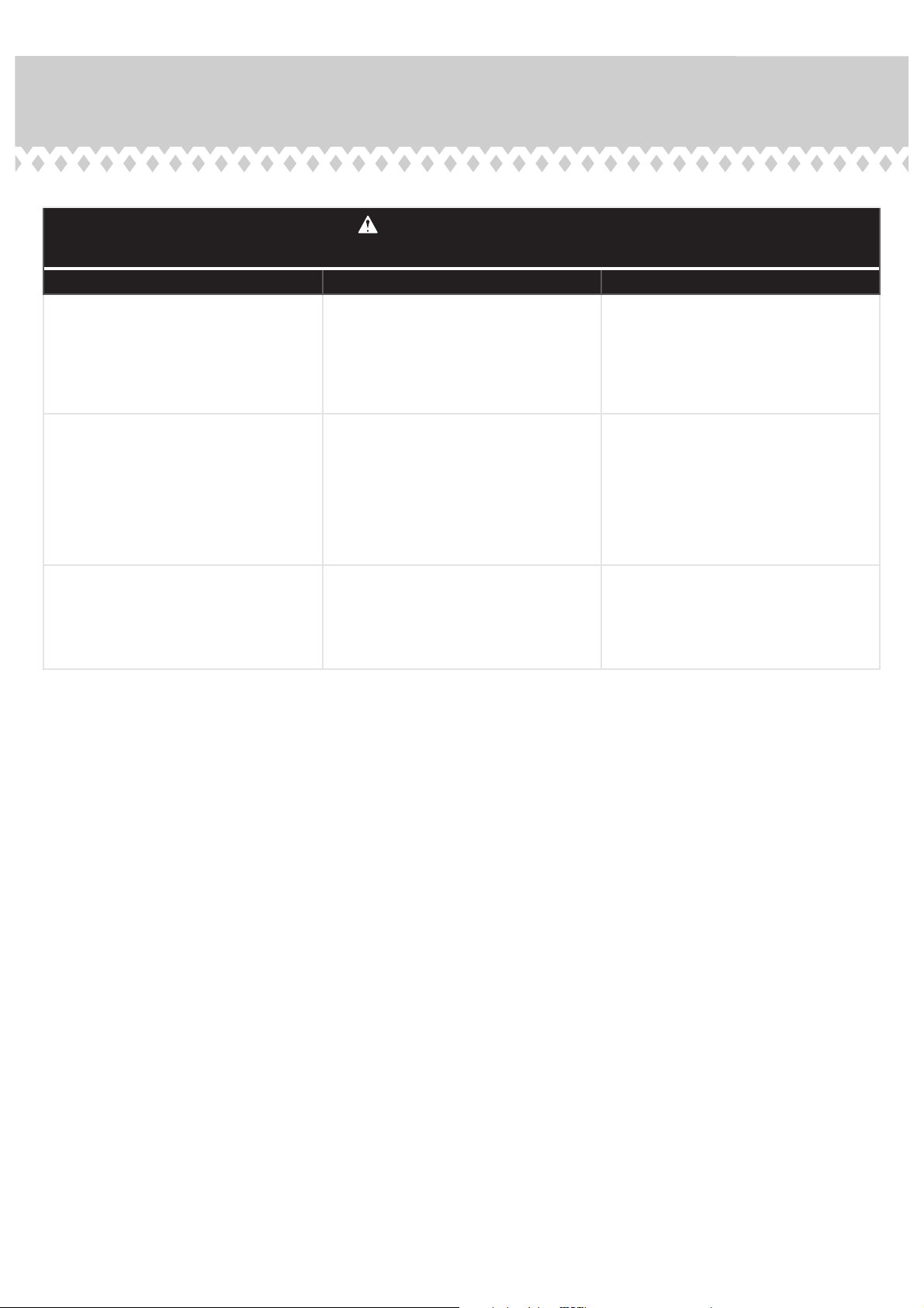
Prière d’utiliser le mobilier à bon escient et avec prudence. Une mauvaise utilisation peut être à l’origine de risques
d’accident ou peut endommager le mobilier et les articles ménagers. Lire attentivement le tableau suivant.
À surveiller : Danger éventuel : Solution :
• Tablettes ou tiroirs surchargés.
• En cas de chargement inadéquat
’élément peut être lourd du haut.
l
• Risque de blessure.
• Du mobilier mal équilibré risque de se
renverser.
• Tablettes et tiroirs surchargés risquent de
casser.
• Ne jamais excéder les limites de poids
indiquées dans les instructions.
• Pour charger les tablettes et tiroirs,
commencer par remplir celui du bas pour
fi nir par celui du haut. Placer les articles
plus lourds sur les tablettes inférieures ou
dans les tiroirs inférieurs.
• Déplacement inadéquat d’un mobilier qui
n’est pas conçu pour avoir des roulettes et
n’en est pas équipé.
• Il est dangereux de placer des téléviseurs
sur des meubles que ne sont pas prévus à
cet e et.
• Le mobilier risque de se renverser ou de
casser en cas de déplacement inadéquat.
• Blessure physique. Le mobilier peut être
très lourd.
• Défaillance des dessus surtout avec les
éléments de double piédestaux (tiroirs en
chaque extrémité).
• Risque de blessures graves, voire mortelles.
Les téléviseurs peuvent être particulièrement
lourds. De plus, le poids et l’emplacement
du tube image ont tendance à rendre les
téléviseurs instables et enclins à tomber vers
l’avant.
• Décharger les tablettes et tiroirs en
commençant par celui du haut avant de
déplacer l’élément.
• Ne pas pousser le meuble, surtout sur
la moquette. Se faire aider par une autre
personne pour soulever l'élément et le
mettre en place.
• Supporter la section centrale du dessus
lorsque l’on soulève le meuble.
• Ce produit n’est pas destiné à supporter
un téléviseur.
Page 37
Page 38

ADVERTENCIA
Por favor use el mobiliario correcta y seguramente. El mal uso puede causar riesgos de seguridad
o daño a las unidades o artículos domésticos. Cuidadosamente lea la tabla a continuación.
Esté alerto de: Puede ocurrir: Evitar el problema:
• Estantes o cajones sobrecargados.
• Cargar el pr
puede causar la inestabilidad.
oducto de manera inadecuada
• Riesgo de lesiones.
• El mobiliario inestable puede volcarse.
• Estantes y cajones sobrecargados pueden
romperse.
• Nunca exceder los límites de peso
indicados en las instrucciones.
• Cargue los estantes y cajones a partir de
la base y trabaje hacia arriba. Coloque los
artículos más pesados sobre los estantes
inferiores o en los cajones inferiores.
• Mover incorrectamente el mobiliario que
no está diseñado y provisto con ruedecitas.
• Es peligroso colocar los televisores
sobre unidades de mobiliario que no están
diseñadas para soportar un televisor.
• La inclinación o rotura del mobiliario es
posible si se mueve de manera inadecuada.
• Lesión física. El mobiliario puede ser muy
pesado.
• Rotura de las superfi cies especialmente
las unidades con dos pedestales (con
cajones en cada extremo).
• Riesgo de lesiones o muerte. Los
televisores pueden ser muy pesados.
Además, el peso y la ubicación del tubo de
imagen tienden a causar la inestabilidad
de televisores y propensa a volcarse hacia
adelante.
• Descargue los estantes y cajones desde
arriba hacia abajo antes de mover la unidad.
• No empuje la unidad, especialmente sobre
un piso alfombrado. Pide la ayuda de otra
persona para levantar la unidad y colocarla
en lugar.
• Soporte la sección central del panel
superior cuando levanta el mueble.
• Este producto no está diseñado para
soportar un televisor.
Page 38
Page 39

5-YEAR LIMITED WARRANTY
1. The company provides limited warranty coverage to the original purchaser of
this product for a period of five years from the date of purchase against de fects in
materials or workmanship of our furniture components.
As used in this Warranty, “defect” means imperfections in components which
substantially impair the utility of the product. This Warranty gives you specifi c
legal rights, and you may also have other rights which vary from state to state.
2. There is no warranty coverage for defects or conditions that result from the
failure to follow product assembly instructions, information or warnings, misuse or
abuse, intentional damage, fire, flood, alteration or modifi cation of the product, or
use of the product in a manner inconsistent with its intended use, nor any
condition resulting from incorrect or inadequate maintenance, cleaning, or care.
There is also no warranty coverage for rented products or any products purchased
“used” or “as is”, at a distress or going-out-of busine ss sale, or from a liquidator.
3. As the exclusive remedy under this Warranty, we will (at its sole option) repair,
replace or refund the value of any defective furniture component. We may require
independent confirmation of the claimed defect and proof of purchase.
Replacement parts will be warranted for only the remaining period of the original
Warranty. WE SHALL HAVE NO LIABILITY for ANY INCIDENTAL OR
CONSEQUENTIAL DAMAGES OF ANY KIND and all such damages are
EXCLUDED FROM THIS WARRANTY, such as loss of use, disassembly,
transportation, labor or damage to property on or near the product. Some states do
not allow the exclusion or limitation of incidental or consequential damages, so the
above limitation or exclusion may not apply to you.
G
ARANTIE LIMITÉE DE 5 ANS
1.
La société offre une couverture de garantie limitée à l'acheteur d'origine de ce
produit pour une période de cinq ans à compter de la date d'achat contre les défauts
de matériaux ou de fabrication de nos composants de meubles.
Tel qu'utilisé dans cette garantie, «défaut» signifie des imperfections dans les
composants qui nuisent considérablement à l'utilité du produit. Cette garantie vous
donne des droits légaux spéci fi ques, et vous pouvez également avoir d'autres droits
qui varient d'un état à l'autre.
2.
Il n'y a aucune couverture de garantie pour les défauts ou conditions résultant du
non-respect des instructions d'assemblage du produit, des informations ou des
avertissements, d'une mauvaise utilisation ou d'un abus, des dommages
intentionnels, du feu, des inondations, de l'altération ou de la modification du
produit, ou de l'utilisation du produit d'une manière incompatible avec son
utilisation prévue, ni aucune condition résultant d'un entretien, d'un nettoyage ou
d'un entretien incorrects ou inadéquats. Il n'y a également aucune couverture de
garantie pour les produits loués ou les produits achetés «d'occasion» ou «tels quels»,
lors d'une vente de détresse ou de cessation d'activité, ou auprès d'un liquidateur.
3.
En tant que recours exclusif en vertu de cette garantie, nous réparerons,
remplacerons ou rembourserons (à sa seule discrétion) la valeur de tout élément de
meuble défectueux. Nous pouvons exiger une confirmation indépendante du défaut
réclamé et une preuve d'achat. Les pièces de rechange ne seront garanties que pour
la période restante de la garantie d'origine. NOUS N'ASSUMONS AUCUNE
RESPONSABILITÉ POUR TOUT DOMMAGE ACCIDENTEL OU CONSÉCUTIF
DE QUELQUE SORTE QUE CE SOIT, et tous ces dommages sont EXCLUS DE
CETTE GARANTIE, tels que la perte d'utilisation, le démontage, le transport, la
main-d'œuvre ou les dommages matériels sur ou à proximité du produit. Certains
États n'autorisent pas l'exclusion ou la limitation des dommages accessoires ou
indirects, de sorte que la limitation ou l'exclusion ci-dessus peut ne pas s'appliquer à
vous.
4. This Warranty applies only to warranted defects that first arise and are
reported to us within the warranty coverage period. The Warranty cannot be
transferred to subsequent owners or users of the product, and it shall be
immediately void in the event the product is resold, transferred, leased or rented
to any third party or person other than the original purchaser.
5. THERE ARE NO OTHER WARRANTIES APPLICABLE TO THIS
PRODUCT. Under the laws of certain states, there may be no implied warranties
from us and all implied warranties, INCLUDING ANY IMPLIED WARRANTY
OF MERCHANTABILITY OR FITNESS FOR A PARTICULAR PURPOSE are
disclaimed where allowed by law. TO THE EXTENT ANY IMPLIED
WARRANTIES ARE APPLICABLE, ANY IMPLIED WARRANTIES,
INCLUDING ANY IMPLIED WARRANTY OF MERCHANTABILITY OR
FITNESS FOR A PARTICULAR PURPOSE, ARE LIMITED IN DURATION TO
THE DURATION OF THIS EXPRESS WARRANTY or the minimum period
allowed by law, whichever is shorter. Some states do not allow limitations on how
long an implied Warranty lasts, so the above limitation may not apply to you.
4. Cette garantie s'applique uniquement aux défauts garantis qui surviennent en
premier et qui nous sont signalés pendant la période de couverture de la garantie.
La garantie ne peut pas être transférée aux propriétaires ou utilisateurs ultérieurs
du produit, et elle sera immédiatement annulée si le produit est revendu,
transféré, loué ou loué à un tiers ou à une personne autre que l'acheteur d'origine.
5. IL N'Y A AUCUNE AUTRE GARANTIE APPLICABLE À CE PRODUIT. En
vertu des lois de certains États, il ne peut y avoir aucune garantie implicite de
notre part et toutes les garanties implicites, Y COMPRIS TOUTE GARANTIE
IMPLICITE DE QUALITÉ MARCHANDE OU D'ADÉQUATION À UN
USAGE PARTICULIER, sont exclues lorsque la loi le permet. DANS LA
MESURE OU TOUTE GARANTIE IMPLICITE EST APPLICABLE, TOUTE
GARANTIE IMPLICITE, Y COMPRIS TOUTE GARANTIE IMPLICITE DE
QUALITÉ MARCHANDE OU D'ADÉQUATION À UN USAGE
PARTICULIER, EST LIMITÉE EN DURÉE À LA DURÉE DE CETTE
GARANTIE EXPRESSE ou à la période minimale autorisée par la loi, selon la
plus courte des deux. Certains états n'autorisent pas les limitations de la durée
d'une garantie implicite, il se peut donc que la limitation ci-dessus ne s'applique
pas à vous.
GARANTÍA LIMITADA DE 5 AÑOS
1. La compañía brinda cobertura de garantía limitada al comprador original de este
producto por un período de cinco años a partir de la fecha de compra contra defectos
en materiales o mano de obra de nuestros componentes de muebles.
Como se usa en esta Garantía, "defecto" significa imperfecciones en los componentes
que perjudican sustancialmente la utilidad del producto. Esta Garantía le otorga
derechos legales específicos, y también puede tener otros derechos que varían de
estado a estado.
2. No hay cobertura de garantía por defectos o condiciones que resulten del
incumplimiento de las instrucciones de ensamblaje del producto, información o
advertencias, mal uso o abuso, daño intencional, incendio, inundación, alteración o
modificación del producto, o el uso del producto de una manera inconsistente con su
uso previsto, ni ninguna condición resultante de mantenimiento, limpieza o cuidado
incorrectos o inadecuados. Tampoco hay cobertura de garantía para los productos
alquilados o cualquier producto comprado "usado" o "tal como está", en una venta de
emergencia o de cierre de negocio, o de un liquidador.
3. Como remedio exclusivo bajo esta Garantía, repararemos, a su exclusivo criterio,
reemplazaremos o reembolsaremos el valor de cualquier componente defectuoso del
mueble. Es posible que solicitemos una confirmación independiente del defecto
reclamado y un comprobante de compra. Las piezas de repuesto estarán garantizadas
solo por el período restante de la Garantía original. NO TENDREMOS NINGUNA
RESPONSABILIDAD por NINGÚN DAÑO INCIDENTAL O CONSECUENTE DE
NINGÚN TIPO y todos los daños están EXCLUIDOS DE ESTA GARANTÍA, tales
como pérdida de uso, desmontaje, transporte, mano de obra o daños a la propiedad en
o cerca del producto. Algunos estados no permiten la exclusión o limitación de daños
incidentales o consecuentes, por lo que la limitación o exclusión anterior puede no
aplicarse en su caso.
4. Esta garantía se aplica solo a los defectos garantizados que surgen por primera
vez y se nos informan dentro del período de cobertura de la garantía. La Garantía
no puede transferirse a los propietarios o usuarios posteriores del producto, y será
nula de inmediato en caso de que el producto sea revendido, transferido,
arrendado o alquilado a un tercero o persona que no sea el comprador original.
5. NO HAY OTRA GARANTÍA APLICABLE A ESTE PRODUCTO. Según las
leyes de ciertos estados, es posible que no existan garantías implícitas de nuestra
parte y todas las garantías implícitas, INCLUIDA CUALQUIER GARANTÍA
IMPLÍCITA DE COMERCIABILIDAD O IDONEIDAD PARA UN
PROPÓSITO EN PARTICULAR, se rechazan donde lo permita la ley. EN LA
MEDIDA EN QUE CUALQUIER GARANTÍA IMPLÍCITA SON APLICABLES,
CUALQUIER GARANTÍA IMPLÍCITA, INCLUYENDO CUALQUIER
GARANTÍA IMPLÍCITA DE COMERCIABILIDAD O APTITUD PARA UN
PROPÓSITO EN PARTICULAR, ESTÁN LIMITADAS EN LA DURACIÓN DE
LA DURACIÓN DE ESTA GARANTÍA EXPRESA o el período mínimo
permitido por la ley, lo que sea más corto permitido por la ley. Algunos estados
no permiten limitaciones sobre la duración de una Garantía implícita, por lo que
la limitación anterior puede no aplicarse en su caso.
Page 39
 Loading...