

Unify OpenSpace CP600, OpenSpace CP400, OpenSpace CP200, OpenSpace CP205 Administration Manual
Page 1

OpenScape Desk Phone
CP200/CP205/CP400/CP600
Phone Administration HFA
Administration Manual
A31003-C1000-M102-5-76A9
Page 2

Our Quality and Environmental Management Systems are
implemented according to the requirements of the ISO9001 and
ISO14001 standards and are certified by an external certification
company.
Copyright © Unify Software and Solutions GmbH & Co. KG 09/2017
Mies-van-der-Rohe-Str. 6, 80807 Munich/Germany
All rights reserved.
Reference No.: A31003-C1000-M102-5-76A9
The information provided in this document contains merely general descriptions or
characteristics of perfo rmance which in case of actual use do not always apply as
described or which may change as a result of further development of the products.
An obligation to provide the respective cha racteristics shall only exist if expressly agreed in
the terms of contract.
Availability and technical specifications are subject to change without notice.
Unify, OpenScape, OpenStage and HiPath are registered trademarks of Unify Software and
Solutions GmbH & Co. KG. All other company, brand, product and service names are
trademarks or registered trademarks of their respective holders.
unify.com
Page 3

bkTOC.fm
Nur für den internen Gebrauch Content
Content 0
1 Overview . . . . . . . . . . . . . . . . . . . . . . . . . . . . . . . . . . . . . . . . . . . . . . . . . . . . . . . . . . . . . . 8
1.1 Important Notes . . . . . . . . . . . . . . . . . . . . . . . . . . . . . . . . . . . . . . . . . . . . . . . . . . . . . . . . 8
1.2 Maintenance Notes . . . . . . . . . . . . . . . . . . . . . . . . . . . . . . . . . . . . . . . . . . . . . . . . . . . . . 9
1.3 Product-oriented environmental protection . . . . . . . . . . . . . . . . . . . . . . . . . . . . . . . . . . . 9
1.4 Labeling . . . . . . . . . . . . . . . . . . . . . . . . . . . . . . . . . . . . . . . . . . . . . . . . . . . . . . . . . . . . . . 9
1.5 About the Manual. . . . . . . . . . . . . . . . . . . . . . . . . . . . . . . . . . . . . . . . . . . . . . . . . . . . . . 10
1.6 Conventions for this Document . . . . . . . . . . . . . . . . . . . . . . . . . . . . . . . . . . . . . . . . . . . 11
1.7 The OpenScape Desk Phone CP Family. . . . . . . . . . . . . . . . . . . . . . . . . . . . . . . . . . . . 11
1.7.1 OpenScape Desk Phone CP600. . . . . . . . . . . . . . . . . . . . . . . . . . . . . . . . . . . . . . . 12
1.7.2 OpenScape Desk Phone CP400. . . . . . . . . . . . . . . . . . . . . . . . . . . . . . . . . . . . . . . 13
1.7.3 OpenScape Desk Phone CP200/CP205. . . . . . . . . . . . . . . . . . . . . . . . . . . . . . . . . 14
1.8 Administration Interfaces . . . . . . . . . . . . . . . . . . . . . . . . . . . . . . . . . . . . . . . . . . . . . . . . 15
1.8.1 Web-based Management (WBM) . . . . . . . . . . . . . . . . . . . . . . . . . . . . . . . . . . . . . . 15
1.8.2 DLS (OpenScape Deployment Service) . . . . . . . . . . . . . . . . . . . . . . . . . . . . . . . . . 15
1.8.3 Local Phone Menu . . . . . . . . . . . . . . . . . . . . . . . . . . . . . . . . . . . . . . . . . . . . . . . . . 15
2 Startup . . . . . . . . . . . . . . . . . . . . . . . . . . . . . . . . . . . . . . . . . . . . . . . . . . . . . . . . . . . . . . . 16
2.1 Prerequisites . . . . . . . . . . . . . . . . . . . . . . . . . . . . . . . . . . . . . . . . . . . . . . . . . . . . . . . . . 16
2.2 Assembling and Installing the Phone. . . . . . . . . . . . . . . . . . . . . . . . . . . . . . . . . . . . . . . 16
2.2.1 Shipment . . . . . . . . . . . . . . . . . . . . . . . . . . . . . . . . . . . . . . . . . . . . . . . . . . . . . . . . . 16
2.2.2 Connectors at the bottom side . . . . . . . . . . . . . . . . . . . . . . . . . . . . . . . . . . . . . . . . 17
2.2.3 Assembly. . . . . . . . . . . . . . . . . . . . . . . . . . . . . . . . . . . . . . . . . . . . . . . . . . . . . . . . . 19
2.2.4 How to Connect the Phone . . . . . . . . . . . . . . . . . . . . . . . . . . . . . . . . . . . . . . . . . . . 20
2.2.5 How to Better Use LAN Network Connections . . . . . . . . . . . . . . . . . . . . . . . . . . . . 21
2.2.6 Key Module . . . . . . . . . . . . . . . . . . . . . . . . . . . . . . . . . . . . . . . . . . . . . . . . . . . . . . 21
2.3 Quick Start . . . . . . . . . . . . . . . . . . . . . . . . . . . . . . . . . . . . . . . . . . . . . . . . . . . . . . . . . . . 22
2.3.1 How to Access the Web Interface (WBM). . . . . . . . . . . . . . . . . . . . . . . . . . . . . . . . 22
2.3.2 Access via Local Phone . . . . . . . . . . . . . . . . . . . . . . . . . . . . . . . . . . . . . . . . . . . . . 23
2.3.2.1 OpenScape Desk Phone CP20X . . . . . . . . . . . . . . . . . . . . . . . . . . . . . . . . . . . 23
2.3.2.2 OpenScape Desk Phone CP400/600 . . . . . . . . . . . . . . . . . . . . . . . . . . . . . . . . 24
2.3.3 How to Set the Terminal Number . . . . . . . . . . . . . . . . . . . . . . . . . . . . . . . . . . . . . . 25
2.3.4 Basic Network Configuration . . . . . . . . . . . . . . . . . . . . . . . . . . . . . . . . . . . . . . . . . . 25
2.3.5 DHCP Resilience. . . . . . . . . . . . . . . . . . . . . . . . . . . . . . . . . . . . . . . . . . . . . . . . . . . 26
2.3.6 Date and Time / SNTP . . . . . . . . . . . . . . . . . . . . . . . . . . . . . . . . . . . . . . . . . . . . . . 27
2.3.7 Extended Network Configuration. . . . . . . . . . . . . . . . . . . . . . . . . . . . . . . . . . . . . . . 27
2.3.8 VLAN Discovery . . . . . . . . . . . . . . . . . . . . . . . . . . . . . . . . . . . . . . . . . . . . . . . . . . . 28
2.3.8.1 Using a Vendor Class. . . . . . . . . . . . . . . . . . . . . . . . . . . . . . . . . . . . . . . . . . . . 28
2.3.8.2 Using Option #43 "Vendor Specific" . . . . . . . . . . . . . . . . . . . . . . . . . . . . . . . . . 33
2.3.9 DLS Server Address . . . . . . . . . . . . . . . . . . . . . . . . . . . . . . . . . . . . . . . . . . . . . . . . 35
2.3.9.1 Using Vendor Class . . . . . . . . . . . . . . . . . . . . . . . . . . . . . . . . . . . . . . . . . . . . . 35
2.3.9.2 Using Option #43 "Vendor Specific" . . . . . . . . . . . . . . . . . . . . . . . . . . . . . . . . . 42
A31003-C1000-M102-5-76A9, 09/2017
OpenScape Desk Phone CP200/CP205/CP400/CP600 HFA, Administration Manual
3
Page 4

bkTOC.fm
Content Nur für den internen Gebrauch
2.3.10 HFA Gateway Settings . . . . . . . . . . . . . . . . . . . . . . . . . . . . . . . . . . . . . . . . . . . . . 44
2.3.11 Using the Web Interface (WBM). . . . . . . . . . . . . . . . . . . . . . . . . . . . . . . . . . . . . . 44
2.3.12 Using the Local Menu. . . . . . . . . . . . . . . . . . . . . . . . . . . . . . . . . . . . . . . . . . . . . . 44
3 Administration . . . . . . . . . . . . . . . . . . . . . . . . . . . . . . . . . . . . . . . . . . . . . . . . . . . . . . . . 45
3.1 Bluetooth Interface . . . . . . . . . . . . . . . . . . . . . . . . . . . . . . . . . . . . . . . . . . . . . . . . . . . . 45
3.1.1 Feature Access. . . . . . . . . . . . . . . . . . . . . . . . . . . . . . . . . . . . . . . . . . . . . . . . . . . . 45
3.2 LAN Settings . . . . . . . . . . . . . . . . . . . . . . . . . . . . . . . . . . . . . . . . . . . . . . . . . . . . . . . . . 46
3.2.1 LAN Port Settings. . . . . . . . . . . . . . . . . . . . . . . . . . . . . . . . . . . . . . . . . . . . . . . . . . 46
3.2.2 VLAN . . . . . . . . . . . . . . . . . . . . . . . . . . . . . . . . . . . . . . . . . . . . . . . . . . . . . . . . . . . 48
3.2.2.1 Automatic VLAN discovery using LLDP-MED . . . . . . . . . . . . . . . . . . . . . . . . . 48
3.2.2.2 Automatic VLAN discovery using DHCP . . . . . . . . . . . . . . . . . . . . . . . . . . . . . 49
3.2.2.3 Manual configuration of a VLAN ID . . . . . . . . . . . . . . . . . . . . . . . . . . . . . . . . . 50
3.3 IP Network Parameters . . . . . . . . . . . . . . . . . . . . . . . . . . . . . . . . . . . . . . . . . . . . . . . . . 52
3.3.1 Quality of Service (QoS). . . . . . . . . . . . . . . . . . . . . . . . . . . . . . . . . . . . . . . . . . . . . 52
3.3.1.1 Layer 2 / 802.1p. . . . . . . . . . . . . . . . . . . . . . . . . . . . . . . . . . . . . . . . . . . . . . . . 52
3.3.1.2 Layer 3 / Diffserv . . . . . . . . . . . . . . . . . . . . . . . . . . . . . . . . . . . . . . . . . . . . . . . 53
3.3.2 Use DHCP . . . . . . . . . . . . . . . . . . . . . . . . . . . . . . . . . . . . . . . . . . . . . . . . . . . . . . . 55
3.3.3 IP Address - Manual Configuration. . . . . . . . . . . . . . . . . . . . . . . . . . . . . . . . . . . . . 57
3.3.4 Default Route/Gateway . . . . . . . . . . . . . . . . . . . . . . . . . . . . . . . . . . . . . . . . . . . . . 58
3.3.5 Specific IP Routing . . . . . . . . . . . . . . . . . . . . . . . . . . . . . . . . . . . . . . . . . . . . . . . . . 59
3.3.6 DNS . . . . . . . . . . . . . . . . . . . . . . . . . . . . . . . . . . . . . . . . . . . . . . . . . . . . . . . . . . . . 60
3.3.6.1 DNS Domain Name . . . . . . . . . . . . . . . . . . . . . . . . . . . . . . . . . . . . . . . . . . . . . 60
3.3.6.2 Terminal Hostname . . . . . . . . . . . . . . . . . . . . . . . . . . . . . . . . . . . . . . . . . . . . . 61
3.3.7 Configuration & Update Service (DLS). . . . . . . . . . . . . . . . . . . . . . . . . . . . . . . . . . 62
3.3.8 SNMP . . . . . . . . . . . . . . . . . . . . . . . . . . . . . . . . . . . . . . . . . . . . . . . . . . . . . . . . . . . 64
3.4 OpenScape Service Menu . . . . . . . . . . . . . . . . . . . . . . . . . . . . . . . . . . . . . . . . . . . . . . 67
3.5 System Settings . . . . . . . . . . . . . . . . . . . . . . . . . . . . . . . . . . . . . . . . . . . . . . . . . . . . . . 68
3.5.1 System Identity. . . . . . . . . . . . . . . . . . . . . . . . . . . . . . . . . . . . . . . . . . . . . . . . . . . . 68
3.5.2 HFA Gateway Settings . . . . . . . . . . . . . . . . . . . . . . . . . . . . . . . . . . . . . . . . . . . . . . 68
3.5.3 HFA Emergency Gateway Settings . . . . . . . . . . . . . . . . . . . . . . . . . . . . . . . . . . . . 70
3.5.4 Server and Standby Server ports . . . . . . . . . . . . . . . . . . . . . . . . . . . . . . . . . . . . . . 71
3.5.5 Redundancy . . . . . . . . . . . . . . . . . . . . . . . . . . . . . . . . . . . . . . . . . . . . . . . . . . . . . . 72
3.5.6 Emergency number . . . . . . . . . . . . . . . . . . . . . . . . . . . . . . . . . . . . . . . . . . . . . . . . 74
3.5.7 LIN . . . . . . . . . . . . . . . . . . . . . . . . . . . . . . . . . . . . . . . . . . . . . . . . . . . . . . . . . . . . . 74
3.5.8 Not Used Timeout. . . . . . . . . . . . . . . . . . . . . . . . . . . . . . . . . . . . . . . . . . . . . . . . . . 75
3.5.9 Energy Saving . . . . . . . . . . . . . . . . . . . . . . . . . . . . . . . . . . . . . . . . . . . . . . . . . . . . 76
3.5.9.1 Energy Efficient Ethernet (OpenScape Desk Phone CP205/CP400/600 only) 76
3.5.10 Date and Time . . . . . . . . . . . . . . . . . . . . . . . . . . . . . . . . . . . . . . . . . . . . . . . . . . . 76
3.5.10.1 SNTP is Available, but no Automatic Configuration by DHCP Server . . . . . . 77
3.5.11 Security. . . . . . . . . . . . . . . . . . . . . . . . . . . . . . . . . . . . . . . . . . . . . . . . . . . . . . . . . 79
3.5.11.1 System. . . . . . . . . . . . . . . . . . . . . . . . . . . . . . . . . . . . . . . . . . . . . . . . . . . . . . 79
3.5.11.2 Access control . . . . . . . . . . . . . . . . . . . . . . . . . . . . . . . . . . . . . . . . . . . . . . . . 81
3.6 Dialing . . . . . . . . . . . . . . . . . . . . . . . . . . . . . . . . . . . . . . . . . . . . . . . . . . . . . . . . . . . . . . 82
3.6.1 Canonical Dialing Configuration . . . . . . . . . . . . . . . . . . . . . . . . . . . . . . . . . . . . . . . 82
A31003-C1000-M102-5-76A9, 09/2017
4 OpenScape Desk Phone CP200/CP205/CP400/CP600 HFA, Administration Manual
Page 5

bkTOC.fm
Nur für den internen Gebrauch Content
3.6.2 Canonical Dial Lookup . . . . . . . . . . . . . . . . . . . . . . . . . . . . . . . . . . . . . . . . . . . . . . 85
3.7 Distinctive Ringing . . . . . . . . . . . . . . . . . . . . . . . . . . . . . . . . . . . . . . . . . . . . . . . . . . . . . 87
3.8 User Mobility . . . . . . . . . . . . . . . . . . . . . . . . . . . . . . . . . . . . . . . . . . . . . . . . . . . . . . . . . 91
3.9 Transferring Phone Software, Application, and Media Files . . . . . . . . . . . . . . . . . . . . . 92
3.9.1 FTP/HTTPS Server . . . . . . . . . . . . . . . . . . . . . . . . . . . . . . . . . . . . . . . . . . . . . . . . . 92
3.9.2 Common FTP/HTTPS Settings (Defaults). . . . . . . . . . . . . . . . . . . . . . . . . . . . . . . . 92
3.9.3 Phone Application . . . . . . . . . . . . . . . . . . . . . . . . . . . . . . . . . . . . . . . . . . . . . . . . . . 95
3.9.3.1 Upgrade Using File. . . . . . . . . . . . . . . . . . . . . . . . . . . . . . . . . . . . . . . . . . . . . . 95
3.9.3.2 Upgrade Using FTP/HTTPS Access Data . . . . . . . . . . . . . . . . . . . . . . . . . . . . 95
3.9.3.3 Download/Update Phone Application . . . . . . . . . . . . . . . . . . . . . . . . . . . . . . . . 99
3.9.4 Picture Clips . . . . . . . . . . . . . . . . . . . . . . . . . . . . . . . . . . . . . . . . . . . . . . . . . . . . . 101
3.9.4.1 FTP/HTTPS Access Data. . . . . . . . . . . . . . . . . . . . . . . . . . . . . . . . . . . . . . . . 101
3.9.4.2 Download Picture Clip . . . . . . . . . . . . . . . . . . . . . . . . . . . . . . . . . . . . . . . . . . 103
3.9.5 LDAP Template. . . . . . . . . . . . . . . . . . . . . . . . . . . . . . . . . . . . . . . . . . . . . . . . . . . 104
3.9.5.1 FTP/HTTPS Access Data. . . . . . . . . . . . . . . . . . . . . . . . . . . . . . . . . . . . . . . . 104
3.9.5.2 Download LDAP Template . . . . . . . . . . . . . . . . . . . . . . . . . . . . . . . . . . . . . . . 106
3.9.6 Screensaver . . . . . . . . . . . . . . . . . . . . . . . . . . . . . . . . . . . . . . . . . . . . . . . . . . . . . 107
3.9.6.1 FTP/HTTPS Access Data. . . . . . . . . . . . . . . . . . . . . . . . . . . . . . . . . . . . . . . . 107
3.9.6.2 Download Screensaver . . . . . . . . . . . . . . . . . . . . . . . . . . . . . . . . . . . . . . . . . 109
3.9.7 Ringer File. . . . . . . . . . . . . . . . . . . . . . . . . . . . . . . . . . . . . . . . . . . . . . . . . . . . . . . 110
3.9.7.1 FTP/HTTPS Access Data. . . . . . . . . . . . . . . . . . . . . . . . . . . . . . . . . . . . . . . . 111
3.9.7.2 Download Ringer File . . . . . . . . . . . . . . . . . . . . . . . . . . . . . . . . . . . . . . . . . . . 113
3.9.8 Dongle Key . . . . . . . . . . . . . . . . . . . . . . . . . . . . . . . . . . . . . . . . . . . . . . . . . . . . . . 114
3.9.8.1 FTP/HTTPS Access Data. . . . . . . . . . . . . . . . . . . . . . . . . . . . . . . . . . . . . . . . 114
3.9.8.2 Download Dongle Key File . . . . . . . . . . . . . . . . . . . . . . . . . . . . . . . . . . . . . . . 116
3.10 UC Server . . . . . . . . . . . . . . . . . . . . . . . . . . . . . . . . . . . . . . . . . . . . . . . . . . . . . . . . . 117
3.11 Corporate Phonebook: Directory Settings . . . . . . . . . . . . . . . . . . . . . . . . . . . . . . . . . 118
3.11.1 LDAP. . . . . . . . . . . . . . . . . . . . . . . . . . . . . . . . . . . . . . . . . . . . . . . . . . . . . . . . . . 118
3.11.2 Canonical Dial Settings . . . . . . . . . . . . . . . . . . . . . . . . . . . . . . . . . . . . . . . . . . . . 119
3.11.3 Picture via LDAP . . . . . . . . . . . . . . . . . . . . . . . . . . . . . . . . . . . . . . . . . . . . . . . . . 120
3.12 Speech. . . . . . . . . . . . . . . . . . . . . . . . . . . . . . . . . . . . . . . . . . . . . . . . . . . . . . . . . . . . 122
3.12.1 RTP Base Port . . . . . . . . . . . . . . . . . . . . . . . . . . . . . . . . . . . . . . . . . . . . . . . . . . 122
3.12.2 Codec Preferences . . . . . . . . . . . . . . . . . . . . . . . . . . . . . . . . . . . . . . . . . . . . . . . 123
3.12.3 Display General Phone Information . . . . . . . . . . . . . . . . . . . . . . . . . . . . . . . . . . 125
3.13 Security and Policies . . . . . . . . . . . . . . . . . . . . . . . . . . . . . . . . . . . . . . . . . . . . . . . . . 126
3.13.1 Password . . . . . . . . . . . . . . . . . . . . . . . . . . . . . . . . . . . . . . . . . . . . . . . . . . . . . . 126
3.13.1.1 Troubleshooting: Lost Password . . . . . . . . . . . . . . . . . . . . . . . . . . . . . . . . . 127
3.13.2 Certificates . . . . . . . . . . . . . . . . . . . . . . . . . . . . . . . . . . . . . . . . . . . . . . . . . . . . . 127
3.13.2.1 Generic . . . . . . . . . . . . . . . . . . . . . . . . . . . . . . . . . . . . . . . . . . . . . . . . . . . . . 127
3.13.2.2 Authentication Policy . . . . . . . . . . . . . . . . . . . . . . . . . . . . . . . . . . . . . . . . . . 128
3.14 Restart Phone . . . . . . . . . . . . . . . . . . . . . . . . . . . . . . . . . . . . . . . . . . . . . . . . . . . . . . 129
3.15 Factory Reset . . . . . . . . . . . . . . . . . . . . . . . . . . . . . . . . . . . . . . . . . . . . . . . . . . . . . . 129
3.16 SSH – Secure Shell Access . . . . . . . . . . . . . . . . . . . . . . . . . . . . . . . . . . . . . . . . . . . 130
3.17 Display License Information. . . . . . . . . . . . . . . . . . . . . . . . . . . . . . . . . . . . . . . . . . . . 131
A31003-C1000-M102-5-76A9, 09/2017
OpenScape Desk Phone CP200/CP205/CP400/CP600 HFA, Administration Manual
5
Page 6

bkTOC.fm
Content Nur für den internen Gebrauch
3.18 Web Services Interface (WSI). . . . . . . . . . . . . . . . . . . . . . . . . . . . . . . . . . . . . . . . . . 131
3.19 HPT Interface (For Service Staff) . . . . . . . . . . . . . . . . . . . . . . . . . . . . . . . . . . . . . . . 132
3.20 Diagnostics . . . . . . . . . . . . . . . . . . . . . . . . . . . . . . . . . . . . . . . . . . . . . . . . . . . . . . . . 133
3.20.1 LLDP-MED . . . . . . . . . . . . . . . . . . . . . . . . . . . . . . . . . . . . . . . . . . . . . . . . . . . . . 134
3.20.2 Fault Trace Configuration. . . . . . . . . . . . . . . . . . . . . . . . . . . . . . . . . . . . . . . . . . 136
3.20.3 EasyTrace Profiles . . . . . . . . . . . . . . . . . . . . . . . . . . . . . . . . . . . . . . . . . . . . . . . 142
3.20.3.1 Call Connection . . . . . . . . . . . . . . . . . . . . . . . . . . . . . . . . . . . . . . . . . . . . . . 142
3.20.3.2 Call Log Problems . . . . . . . . . . . . . . . . . . . . . . . . . . . . . . . . . . . . . . . . . . . . 143
3.20.3.3 Call recording. . . . . . . . . . . . . . . . . . . . . . . . . . . . . . . . . . . . . . . . . . . . . . . . 143
3.20.3.4 DAS Connection . . . . . . . . . . . . . . . . . . . . . . . . . . . . . . . . . . . . . . . . . . . . . 144
3.20.3.5 DLS Data Errors. . . . . . . . . . . . . . . . . . . . . . . . . . . . . . . . . . . . . . . . . . . . . . 144
3.20.3.6 HFA registration and security. . . . . . . . . . . . . . . . . . . . . . . . . . . . . . . . . . . . 145
3.20.3.7 Help Application problems . . . . . . . . . . . . . . . . . . . . . . . . . . . . . . . . . . . . . . 145
3.20.3.8 Key Input problems . . . . . . . . . . . . . . . . . . . . . . . . . . . . . . . . . . . . . . . . . . . 146
3.20.3.9 LAN Connectivity problems . . . . . . . . . . . . . . . . . . . . . . . . . . . . . . . . . . . . . 146
3.20.3.10 Messaging application problems . . . . . . . . . . . . . . . . . . . . . . . . . . . . . . . . 147
3.20.3.11 Mobility problems . . . . . . . . . . . . . . . . . . . . . . . . . . . . . . . . . . . . . . . . . . . . 147
3.20.3.12 Phone administration problems . . . . . . . . . . . . . . . . . . . . . . . . . . . . . . . . . 148
3.20.3.13 Phonebook (LDAP) problems . . . . . . . . . . . . . . . . . . . . . . . . . . . . . . . . . . 148
3.20.3.14 Phonebook (local) problems . . . . . . . . . . . . . . . . . . . . . . . . . . . . . . . . . . . 149
3.20.3.15 Server based application problems . . . . . . . . . . . . . . . . . . . . . . . . . . . . . . 149
3.20.3.16 Sidecar problems . . . . . . . . . . . . . . . . . . . . . . . . . . . . . . . . . . . . . . . . . . . . 150
3.20.3.17 Speech problems . . . . . . . . . . . . . . . . . . . . . . . . . . . . . . . . . . . . . . . . . . . . 150
3.20.3.18 Tone problems. . . . . . . . . . . . . . . . . . . . . . . . . . . . . . . . . . . . . . . . . . . . . . 151
3.20.3.19 Web based management. . . . . . . . . . . . . . . . . . . . . . . . . . . . . . . . . . . . . . 151
3.20.3.20 802.1x problems . . . . . . . . . . . . . . . . . . . . . . . . . . . . . . . . . . . . . . . . . . . . 152
3.20.3.21 No Tracing for All Services . . . . . . . . . . . . . . . . . . . . . . . . . . . . . . . . . . . . 153
3.20.4 Bluetooth advanced traces . . . . . . . . . . . . . . . . . . . . . . . . . . . . . . . . . . . . . . . . . 154
3.20.5 QoS Reports. . . . . . . . . . . . . . . . . . . . . . . . . . . . . . . . . . . . . . . . . . . . . . . . . . . . 155
3.20.5.1 Conditions and Thresholds for Report Generation . . . . . . . . . . . . . . . . . . . 155
3.20.5.2 View Session Data. . . . . . . . . . . . . . . . . . . . . . . . . . . . . . . . . . . . . . . . . . . . 158
3.20.6 Miscellaneous. . . . . . . . . . . . . . . . . . . . . . . . . . . . . . . . . . . . . . . . . . . . . . . . . . . 162
3.20.6.1 IP tests. . . . . . . . . . . . . . . . . . . . . . . . . . . . . . . . . . . . . . . . . . . . . . . . . . . . . 162
3.20.6.2 Memory Status Information . . . . . . . . . . . . . . . . . . . . . . . . . . . . . . . . . . . . . 163
3.20.6.3 Core dump . . . . . . . . . . . . . . . . . . . . . . . . . . . . . . . . . . . . . . . . . . . . . . . . . . 165
3.20.7 Remote Tracing – Syslog . . . . . . . . . . . . . . . . . . . . . . . . . . . . . . . . . . . . . . . . . . 166
4 Examples and HowTos . . . . . . . . . . . . . . . . . . . . . . . . . . . . . . . . . . . . . . . . . . . . . . . . 167
4.1 Canonical Dialing . . . . . . . . . . . . . . . . . . . . . . . . . . . . . . . . . . . . . . . . . . . . . . . . . . . . 167
4.1.1 Canonical Dialing Settings . . . . . . . . . . . . . . . . . . . . . . . . . . . . . . . . . . . . . . . . . . 167
4.1.2 Canonical Dial Lookup . . . . . . . . . . . . . . . . . . . . . . . . . . . . . . . . . . . . . . . . . . . . . 168
4.1.2.1 Conversion examples . . . . . . . . . . . . . . . . . . . . . . . . . . . . . . . . . . . . . . . . . . 169
4.2 How to Set Up the Corporate Phonebook (LDAP) . . . . . . . . . . . . . . . . . . . . . . . . . . . 171
4.2.1 Prerequisites. . . . . . . . . . . . . . . . . . . . . . . . . . . . . . . . . . . . . . . . . . . . . . . . . . . . . 171
4.2.2 Create an LDAP Template . . . . . . . . . . . . . . . . . . . . . . . . . . . . . . . . . . . . . . . . . . 172
A31003-C1000-M102-5-76A9, 09/2017
6 OpenScape Desk Phone CP200/CP205/CP400/CP600 HFA, Administration Manual
Page 7

bkTOC.fm
Nur für den internen Gebrauch Content
4.2.3 How to Load the LDAP Template into the Phone . . . . . . . . . . . . . . . . . . . . . . . . . 174
4.2.4 Configure LDAP Access . . . . . . . . . . . . . . . . . . . . . . . . . . . . . . . . . . . . . . . . . . . . 175
4.3 An LLDP-Med Example . . . . . . . . . . . . . . . . . . . . . . . . . . . . . . . . . . . . . . . . . . . . . . . . 175
5 Technical Reference. . . . . . . . . . . . . . . . . . . . . . . . . . . . . . . . . . . . . . . . . . . . . . . . . . . 176
5.1 Default Port List . . . . . . . . . . . . . . . . . . . . . . . . . . . . . . . . . . . . . . . . . . . . . . . . . . . . . . 176
5.2 Troubleshooting: Error Codes . . . . . . . . . . . . . . . . . . . . . . . . . . . . . . . . . . . . . . . . . . . 177
5.3 Troubleshooting: Error Messages . . . . . . . . . . . . . . . . . . . . . . . . . . . . . . . . . . . . . . . . 178
Glossary . . . . . . . . . . . . . . . . . . . . . . . . . . . . . . . . . . . . . . . . . . . . . . . . . . . . . . . . . . . . . . 181
Index . . . . . . . . . . . . . . . . . . . . . . . . . . . . . . . . . . . . . . . . . . . . . . . . . . . . . . . . . . . . . . . . . 188
A31003-C1000-M102-5-76A9, 09/2017
OpenScape Desk Phone CP200/CP205/CP400/CP600 HFA, Administration Manual
7
Page 8

uebersicht.fm
7
7
7
7
Overview
Important Notes
1Overview
1.1 Important Notes
Do not operate the equipment in environments where there is a danger of explosions.
If Power over Ethernet (PoE) is not available: For safety reasons the phone should
only be operating using the supplied plug-in power unit.
Use only original accessories. Using other accessories may be dangerous and will
invalidate the warranty, extended manufacturer’s liability and the CE mark.
Never open the telephone or add-on equipment. If you encounter any problems, contact System Support.
7
Installation requirement for USA, Canada, Norway, Finland, and Sweden: Connection
to networks which use outside cables is prohibited. Only in-house networks are permitted.
For USA and Canada only:
This equipment has been tested and found to comply with the limits for a Class B
digital device, pursuant to Part 15 of the FCC Rules. These limits are designed to
provide reasonable protection against harmful interference when the equipment is
operated in a residential installation. This equipment generates, uses, and can radiate radio frequency energy and, if not installed and used in accordance with the instructions, may cause harmful interference to radio communications. However, there
is no guarantee that interference will not occur in a particular installation. If this
equipment does cause harmful interference to radio or television reception, which
can be determined by turning the equipment off and on, the user is encouraged to
try to correct the interference by one or more of the following measures:
• Reorient or relocate the receiving antenna.
• Increase the separation between the equipment and receiver.
• Connect the equipment into an outlet on a circuit different from that to which the
receiver is connected.
• Consult the dealer or an experienced radio/TV technician for help.
This product is a UL Listed Accessory, I.T.E., in U.S.A. and Canada.
This equipment also complies with the Part 68 of the FCC Rules and the Industrie
Canada CS-03.
A31003-C1000-M102-5-76A9, 09/2017
8 OpenScape Desk Phone CP200/CP205/CP400/CP600 HFA, Administration Manual
Page 9
uebersicht.fm
7
7
7
Overview
Maintenance Notes
1.2 Maintenance Notes
Do not perform maintenance work or servicing of the telephone in environments
where there is a danger of explosions.
Use only original accessories. Using other accessories may be dangerous and will
invalidate the warranty and the CE mark.
Never open the telephone or a key module. If you encounter any problems, contact
System Support.
1.3 Product-oriented environmental protection
Unify is committed in terms of its product strategy to bringing environmentally friendly products
to market, taking account of the entire product life cycle. Unify strives to acquire the relevant
environmental labels for its products in the event that the environmental label programs permit
qualification for individual Unify products.
ENERGY STAR is a U.S. Environmental Protection Agency voluntary program that helps businesses and individuals save money and protect our climate through superior energy efficiency.
Products that earn the ENERGY STAR prevent greenhouse gas emissions by meeting strict
energy efficiency criteria or requirements set by the U.S. Environmental Protection Agency.
Unify is an ENERGY STAR partner participating in the ENERGY STAR program for Enterprise
Servers and Telephony.
The Unify products OpenScape DeskPhone CP200/400/600 have earned the ENERGY STAR.
Learn more at
Special setting instructions for energy-efficient use of the telephone can be found on page 78
in the User Manual.
energystar.gov.
1.4 Labeling
The compliance of the equipment according to EU directives is confirmed
by the CE mark. This Declaration of Conformity and, where applicable, other existing declarations of conformity as well as further information on regulations that restrict the usage of substances or affect the declaration of
substances used in products can be found in the Unify Expert WIKI at
http://wiki.unify.com under the section “Declarations of Conformity”.
A31003-C1000-M102-5-76A9, 09/2017
OpenScape Desk Phone CP200/CP205/CP400/CP600 HFA, Administration Manual
9
Page 10

uebersicht.fm
Overview
About the Manual
1.5 About the Manual
The instructions within this manual will help you in administering and maintaining OpenScape
Desk Phone CP telephones. The instructions contain important information for safe and proper
operation of the phones. Follow them carefully to avoid improper operation and get the most
out of your multi-function telephone in a network environment.
This guide is intended for service providers and network administrators who administer VoIP
services using the OpenScape Desk Phone CP and who have a fundamental understanding of
VoIP, IP networking, and telephony. The tasks described in this guide are not intended for end
users.
These instructions are laid out in a user-oriented manner, which means that you are led through
the functions of the OpenScape Desk Phone CP step by step, wherever expedient. For the users, a separate manual is provided.
You can find further information on the official Unify website (http://www.unify.com/)
and on the Unify Wiki (http://wiki.unify.com/).
A31003-C1000-M102-5-76A9, 09/2017
10 OpenScape Desk Phone CP200/CP205/CP400/CP600 HFA, Administration Manual
Page 11

uebersicht.fm
Overview
Conventions for this Document
1.6 Conventions for this Document
The terms for parameters and functions used in this document are derived from the web interface (WBM). In some cases, the phone’s local menu uses shorter, less specific terms and abbreviations. In a few cases the terminologies differ in wording. If so, the local menu term is added with a preceding "/".
For the parameters described in this document, a WBM screenshot and the path in the local
phone menu is provided.
This document describes the software version V1.
1.7 The OpenScape Desk Phone CP Family
The OpenScape Desk Phone CP phone family comprises the following devices.
• Section 1.7.1, “OpenScape Desk Phone CP600”
• Section 1.7.2, “OpenScape Desk Phone CP400”
• Section 1.7.3, “OpenScape Desk Phone CP200/CP205”
A31003-C1000-M102-5-76A9, 09/2017
OpenScape Desk Phone CP200/CP205/CP400/CP600 HFA, Administration Manual
11
Page 12
uebersicht.fm
1
7
8
5
9
6
4
10
3
2
Overview
The OpenScape Desk Phone CP Family
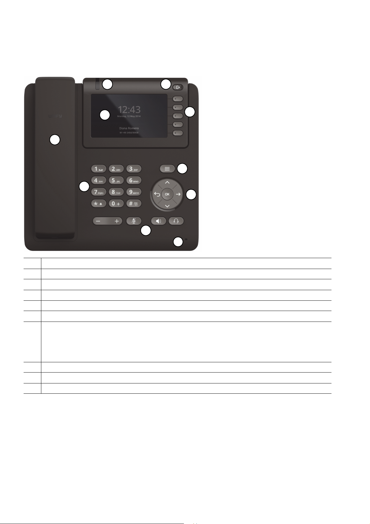
1.7.1 OpenScape Desk Phone CP600
1 With the Handset, the user can pick up and conduct calls in the usual manner.
2The Microphone is used in the speakerphone mode.
3The Display provides intuitive support for telephone operation.
4 With the Menu Key, the user/administrator has access to the user/administrator menu.
5 With the Navigation Keys, the user/administrator can navigate through the various phone functions.
6 With the Soft Keys, the user/administrator can operate the phone´s functions.
7 Audio Keys:
+ and -: Increases/decreases the speaker/headset and handset volume.
Mute: Turns off/on the microphone during conversations.
Speaker: Turns on/off the hands-free mode (speakerphone).
Headset: Switches the audio between handset/speakerphone and headset
8The Notification LED visually signals incoming calls and new voice messages.
9The Keypad is used for entering phone numbers and text.
10 The Out-of-Office Key provides an easy way to set up Call Forwarding and your Presence State.
Tabelle 1-1
12 OpenScape Desk Phone CP200/CP205/CP400/CP600 HFA, Administration Manual
A31003-C1000-M102-5-76A9, 09/2017
Page 13

1.7.2 OpenScape Desk Phone CP400
1
10
8
7
9
5
11
3
6
4
2
uebersicht.fm
Overview
The OpenScape Desk Phone CP Family
1 With the Handset, the user can pick up and conduct calls in the usual manner.
2The Microphone is used in the speakerphone mode.
3The Display provides intuitive support for telephone operation.
4 With the Menu Key, the user/administrator has access to the user/administrator menu.
5 With the Navigation Keys, the user/administrator can navigate through the various phone functions.
6 With the Context Keys, the user/administrator can operate the phone´s functions.
7 Audio Keys:
+ and -: Increases/decreases the speaker/headset and handset volume.
Mute: Turns off/on the microphone during conversations.
Speaker: Turns on/off the hands-free mode (speakerphone).
Headset: Switches the audio between handset/speakerphone and headset
8The Notification LED visually signals incoming calls and new voice messages.
9The Keypad is used for entering phone numbers and text.
10 The Out-of-Office Key provides an easy way to set up Call Forwarding or your Presence State.
11 The Free programmable Keys can be set up with various functions defined by user.
Tabelle 1-2
A31003-C1000-M102-5-76A9, 09/2017
OpenScape Desk Phone CP200/CP205/CP400/CP600 HFA, Administration Manual
13
Page 14
uebersicht.fm
1
10
11
7
9
5
8
3
6
4
2
Overview
The OpenScape Desk Phone CP Family
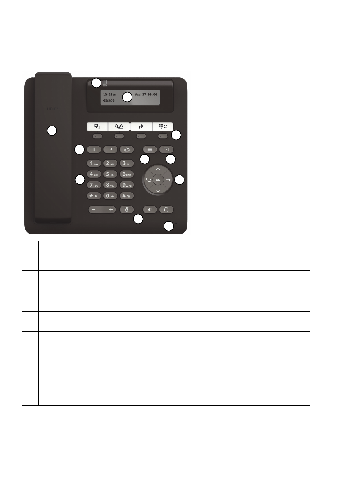
1.7.3 OpenScape Desk Phone CP200/CP205
1 With the Handset, the user can pick up and conduct calls in the usual manner.
2The Microphone is used in the speakerphone mode.
3The Display provides intuitive support for telephone operation.
4 Conversation Keys:
Hold: Places a call in hold.
Transfer: Transfers a current call to another party.
Conference: Initiates a conference call.
5 With the Menu Key, the user has access to the user menu.
6 With the Messages Key, the user has access to the voicemail and the call log.
7 With the Navigation Keys, the user/administrator can navigate through the various phone functions.
8 With the Function Keys, the user can comfortably operate the phone´s functions like Conversations,
Phonebook, Call Forwarding and Redial.
9The Keypad is used for entering phone numbers and text.
10 Audio Keys:
+ and -: Increases/decreases the speaker/headset and handset volume.
Mute: Turns off/on the microphone during conversations.
Speaker: Turns on/off the hands-free mode (speakerphone).
Headset: Switches the audio between handset/speakerphone and headset
11 The Notification LED visually signals incoming calls and new voice messages.
Tabelle 1-3
A31003-C1000-M102-5-76A9, 09/2017
14 OpenScape Desk Phone CP200/CP205/CP400/CP600 HFA, Administration Manual
Page 15
uebersicht.fm
Overview
Administration Interfaces
1.8 Administration Interfaces
You can configure the OpenScape Desk Phone CP by using any of the methods described in
this chapter.
1.8.1 Web-based Management (WBM)
This method employs a web browser for communication with the phone via HTTPS. It is applicable for remote configuration of individual IP phones in your network. Direct access to the
phone is not required.
To use this method, the phone must first obtain IP connectivity.
>
1.8.2 DLS (OpenScape Deployment Service)
The OpenScape Deployment Service (DLS) is an OpenScape Management application for administering phones and soft clients in both OpenScape and non-OpenScape networks. It has
a Java-supported, web-based user interface, which runs on an internet browser. For further information, please refer to the OpenScape Deployment Service Administration Guide.
1.8.3 Local Phone Menu
This method provides direct configuration of the OpenScape Desk Phone CP via the local
phone menu. Direct access to the phone is required.
As long as the IP connection is not properly configured, you have to use this method
>
to set up the phone.
A31003-C1000-M102-5-76A9, 09/2017
OpenScape Desk Phone CP200/CP205/CP400/CP600 HFA, Administration Manual
15
Page 16

inbetriebnahme.fm
Startup
Prerequisites
2Startup
2.1 Prerequisites
The OpenScape Desk Phone CP phone acts as an endpoint client on an IP telephony network
and has the following network requirements:
• An Ethernet connection to a network.
Only use switches in the LAN to which the OpenScape Desk Phone CP phone
7
• A OpenScape Business (with DLI) or OpenScape 4000 Communications System (with Integrated Phone Software Management, IPSM).
• Usage of Voice VLANs is recommended.
• An FTP Server for file transfer, e. g. firmware, configuration data, application software.
Starting with V1 software upgrade can be started via WBM by browsing for image file
through a directory.
• A Dynamic Host Configuration Protocol (DHCP) server (recommended).
• DLS (OpenScape Deployment Service) for advanced configuration and software deployment (recommended).
is connected. An operation at hubs can cause serious malfunctions in the hub
and in the whole network.
For additional information see: http://wiki.unify.com/wiki/IEEE_802.1x.
2.2 Assembling and Installing the Phone
2.2.1 Shipment
• Phone
• Handset
• Handset cable
• Document "Installation and Quick Reference Guide"
A31003-C1000-M102-5-76A9, 09/2017
16 OpenScape Desk Phone CP200/CP205/CP400/CP600 HFA, Administration Manual
Page 17
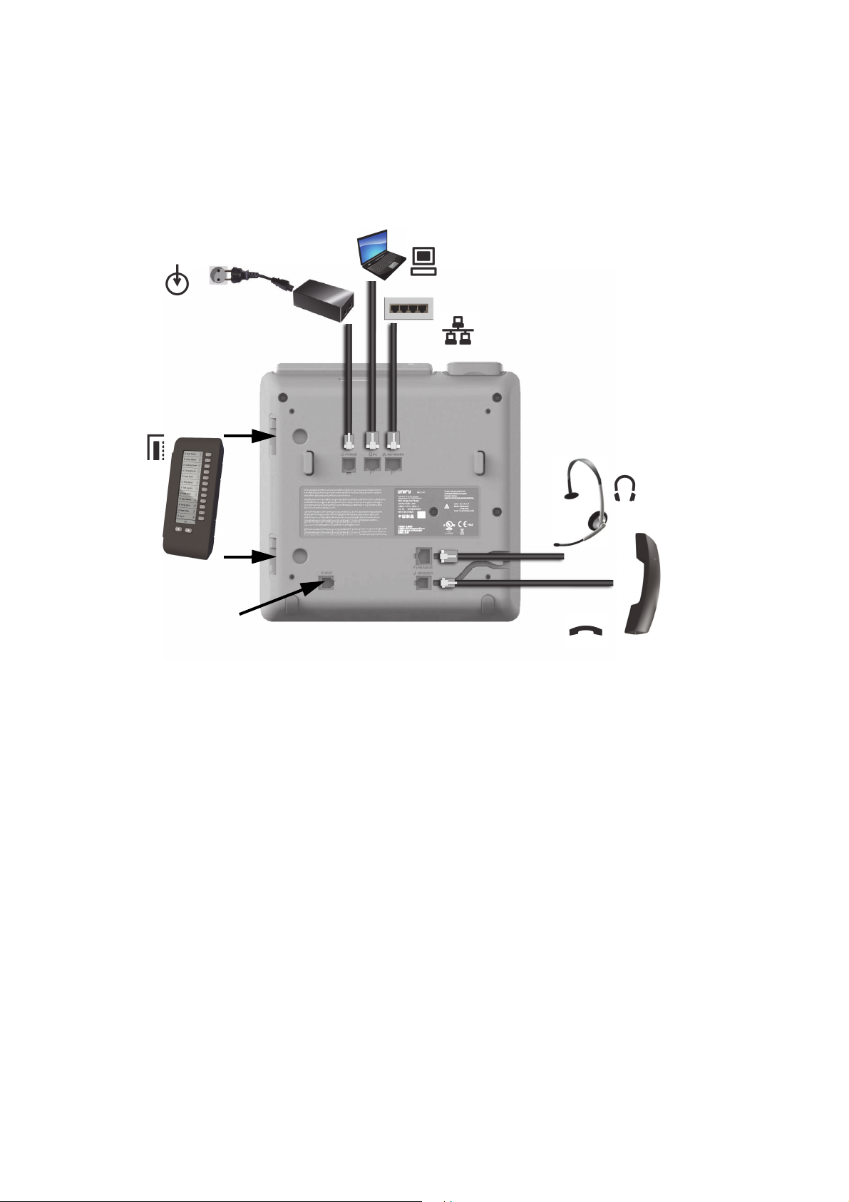
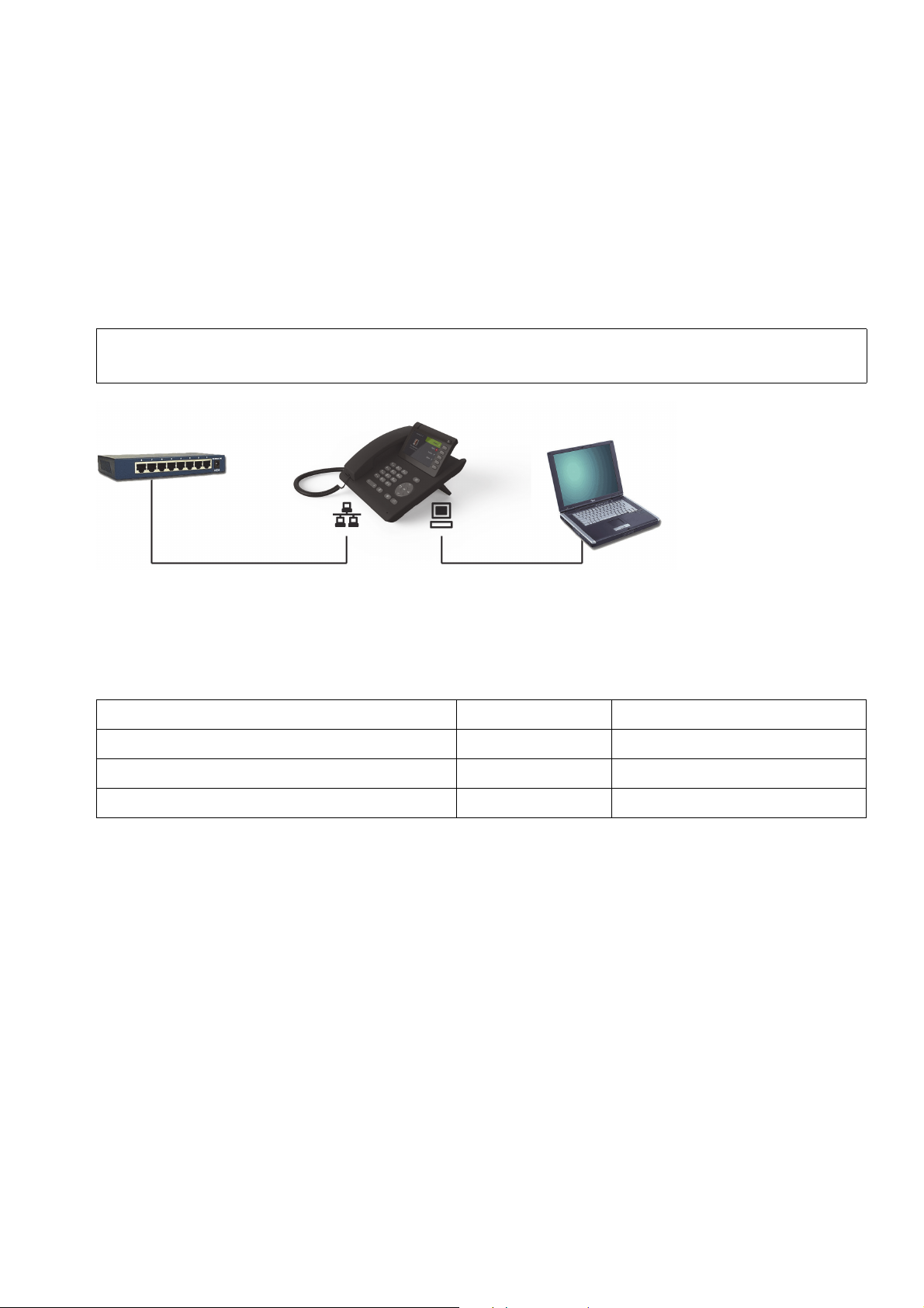
2.2.2 Connectors at the bottom side
Headset
Handset
Network Switch
PC
Key Module
(max. 4)
Power supply
(if required)
Service Interface
OpenScape Desk Phone CP600
inbetriebnahme.fm
Startup
Assembling and Installing the Phone
A31003-C1000-M102-5-76A9, 09/2017
OpenScape Desk Phone CP200/CP205/CP400/CP600 HFA, Administration Manual
17
Page 18
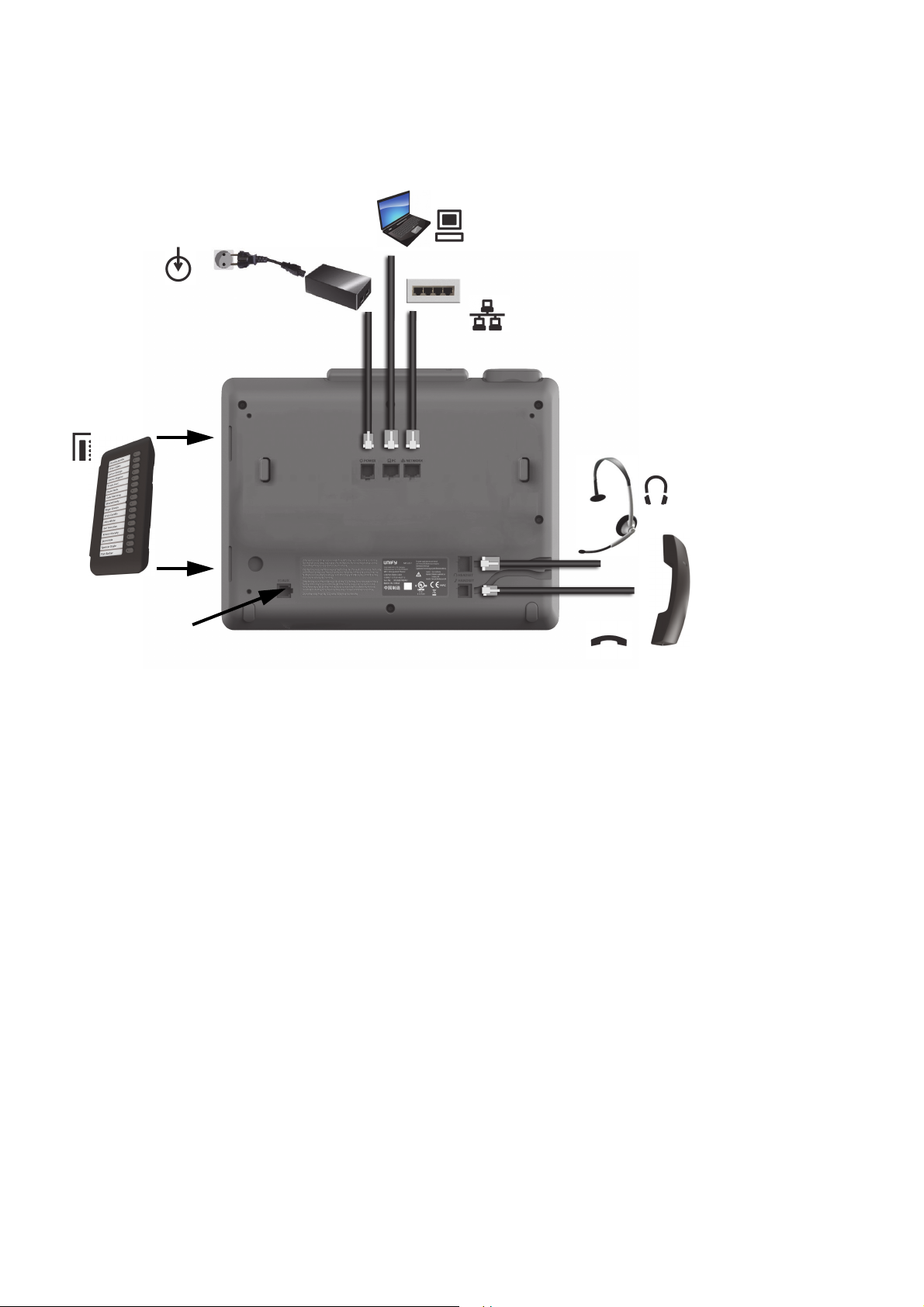
inbetriebnahme.fm
Headset
Handset
Network Switch
PC
Key Module
(max. 2)
Service Interface
Power supply
(if required)
Startup
Assembling and Installing the Phone
OpenScape Desk Phone CP400
18 OpenScape Desk Phone CP200/CP205/CP400/CP600 HFA, Administration Manual
A31003-C1000-M102-5-76A9, 09/2017
Page 19
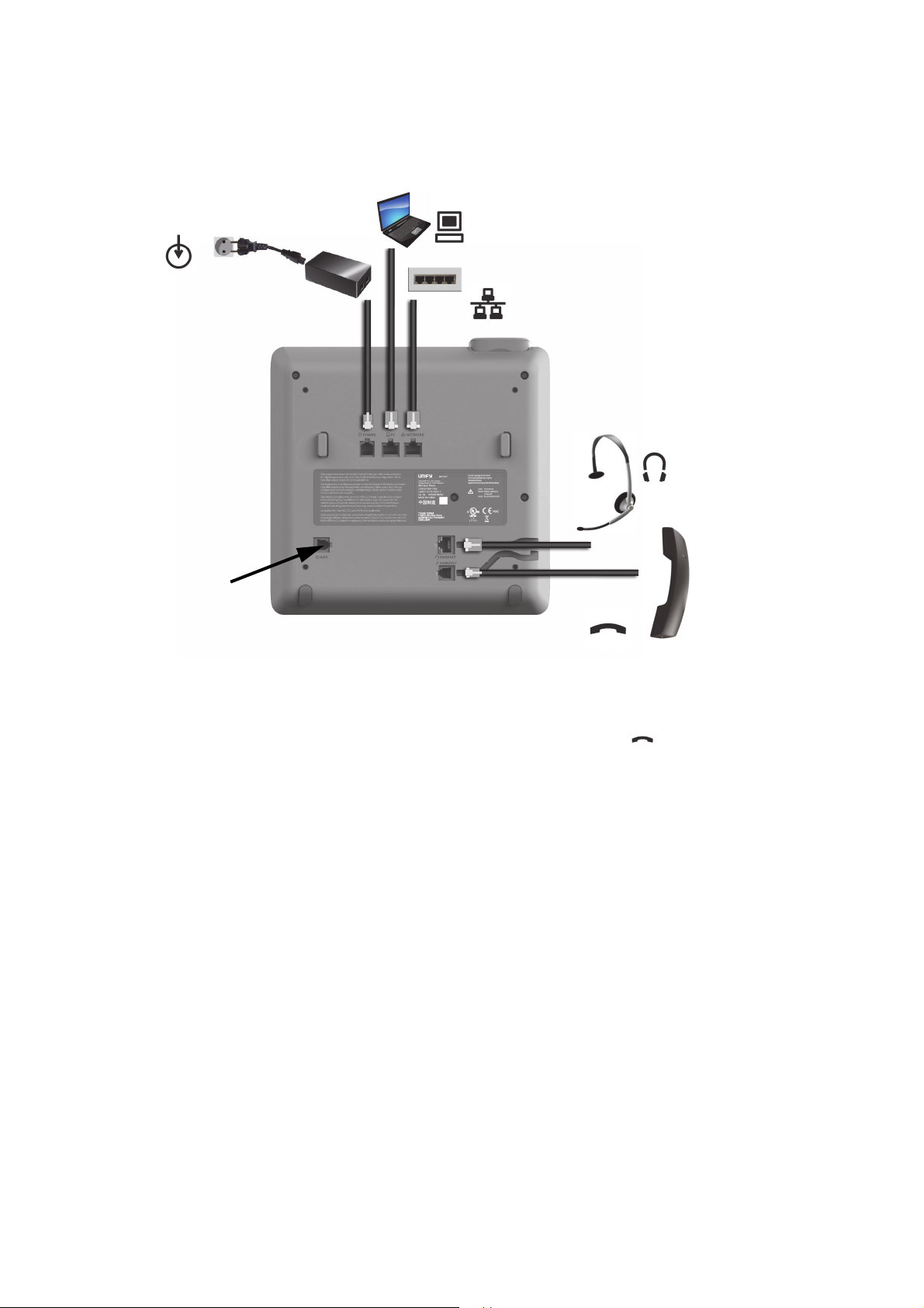
OpenScape Desk Phone CP200/CP205
Headset
Handset
Network Switch
PC
Service Interface
Power supply
(if required)
inbetriebnahme.fm
Startup
Assembling and Installing the Phone
2.2.3 Assembly
Insert the plug on the long end of the handset cable into the jack on the base of the telephone and press the cable into the groove provided for it. Next, insert the plug on the short end
of the handset cable into the jack on the handset.
A31003-C1000-M102-5-76A9, 09/2017
OpenScape Desk Phone CP200/CP205/CP400/CP600 HFA, Administration Manual
19
Page 20
inbetriebnahme.fm
Startup
Assembling and Installing the Phone
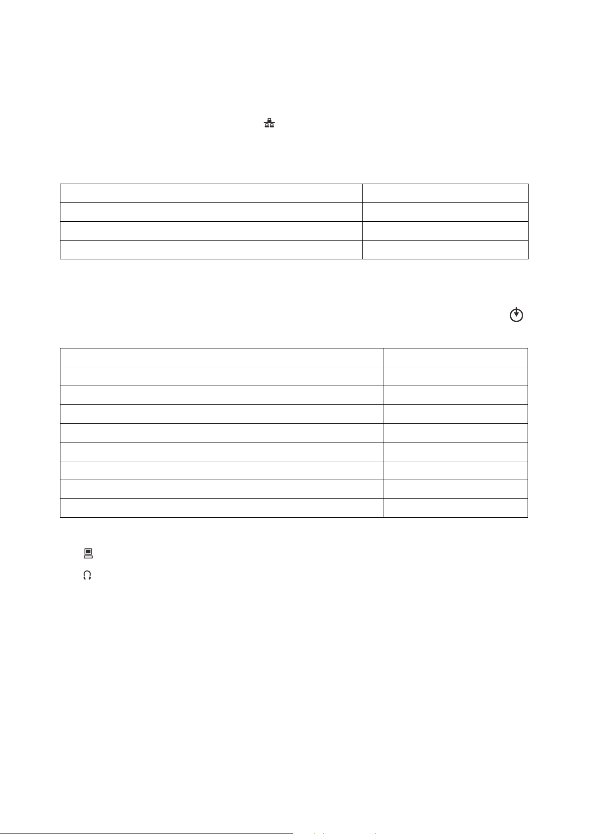
2.2.4 How to Connect the Phone
1. Plug the LAN cable into the connector at the bottom of the telephone and connect the
cable to the LAN resp. switch. If PoE (Power over Ethernet) is to be used, the PSE (Power
Sourcing Equipment) must meet the IEEE 802.3af specification.
For details about the required power supply, see the following table:
Model Power Consumption
OpenScape Desk Phone CP200/CP205 PoE (Power Class 1)
OpenScape Desk Phone CP400 PoE (Power Class 2)
OpenScape Desk Phone CP600
1 If more than one Key Module is connected, a Plug-in Power Supply is required (see below).
2. If Power over Ethernet (PoE) is NOT supported or an OpenScape Desk Phone CP600
phone has more than one Key Module connected:
Plug the power supply unit into the mains. Connect the plug-in power supply unit to the
jack at the bottom of the phone.
1
PoE (Power Class 2)
Plug-in Power Supply Order No.
Power Supply, power cable and plug (Type E+F) for EU L30250-F600-C141
Power Supply, power cable and plug for Great Britain L30250-F600-C142
Power Supply, power cable and plug for USA L30250-F600-C143
Power Supply, power cable and plug for Switzerland L30250-F600-C182
Power Supply, power cable and plug for Italy L30250-F600-C183
Power Supply, power cable and plug for Australia L30250-F600-C184
Power Supply, power cable and plug for South Africa L30250-F600-C185
Power Supply without power cable L30250-F600-C148
3. If applicable, connect the following optional jacks:
• LAN connection to PC
• Headset (accessory)
A31003-C1000-M102-5-76A9, 09/2017
20 OpenScape Desk Phone CP200/CP205/CP400/CP600 HFA, Administration Manual
Page 21
inbetriebnahme.fm
Network
switch
PC
OpenScape Desk Phone CP
Startup
Assembling and Installing the Phone
2.2.5 How to Better Use LAN Network Connections
The OpenScape Desk Phone CP400 and OpenScape Desk Phone CP600 phones provide a
1000 Mbps Ethernet-Switch. This allows you to connect one additional network device (e. g. a
PC) directly via the telephone to the LAN. The direct connection functionality from phone to PC
needs to be activated by administrator first. This type of connection allows you to save one network connection per switch,with the advantage of less network cables and shorter connection
distances.
Do not use this connection for further OpenScape Desk Phone CP,
7
OpenScape Desk Phone IP or OpenStage phones!
2.2.6 Key Module
A key module provides additional program keys. The following table shows which key modules
can be connected to the particular phone types.
Phone Type Key Modules additional keys per module
OpenScape Desk Phone CP200/CP205 - -
OpenScape Desk Phone CP400 2 16
OpenScape Desk Phone CP600 4 12
The configuration of a key on the key module is just the same as the configuration of a phone
key.
A31003-C1000-M102-5-76A9, 09/2017
OpenScape Desk Phone CP200/CP205/CP400/CP600 HFA, Administration Manual
21
Page 22
inbetriebnahme.fm
Startup
Quick Start
2.3 Quick Start
This section describes a typical case: the setup of an OpenScape Desk Phone CP endpoint in
an environment using a DHCP server and the web interface. For different scenarios, cross-references to the corresponding section of the administration chapter are given.
Alternatively, WBM, DLI or DLS (Deployment Service) administration tools can be
>
>
used. Its Plug & Play functionality allows to provide the phone with configuration data
by assigning an existing data profile to the phone’s MAC address or E.164 number.
Any settings made by a DHCP server are not configurable by other configuration
tools.
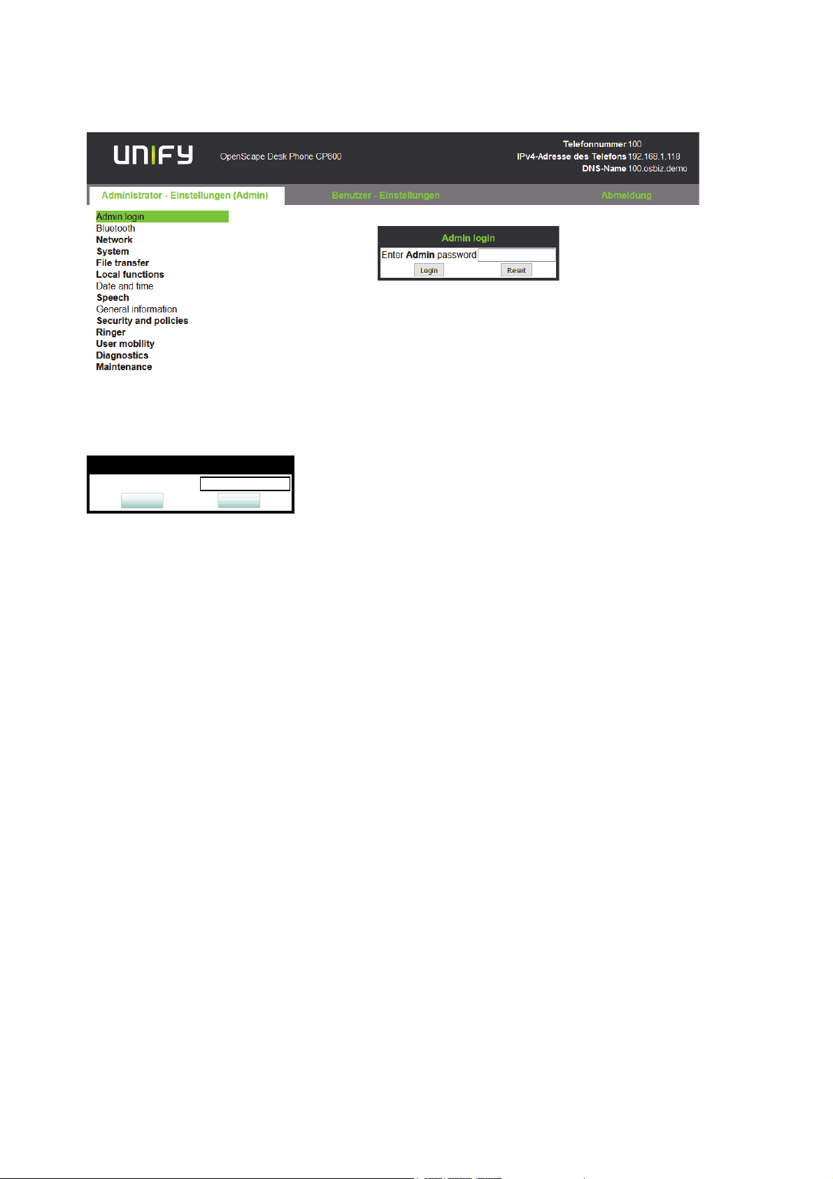
2.3.1 How to Access the Web Interface (WBM)
Prerequisites
• The phone´s IP address or URL is required for accessing the phone´s Web Interface via a
web browser. By default, the phone will automatically search for a DHCP server on startup
and try to obtain IP data and further configuration parameters from that central server.
• If no DHCP server is available in the IP network or if the DHCP parameter is disabled, the
IP address, subnet mask and default gateway/route must be defined manually.
• To obtain the phone´s IP address, proceed as follows:
1. Access the local phone´s Admin menu as described in Section 2.3.2, “Access via Local
Phone”.
• If DHCP is enabled (default): In the Admin menu, navigate to Network > IP configura-
tion > IP address. The IP address is displayed.
• If DHCP is disabled or if no DHCP server is available in the IP network, the IP address,
Subnet Mask and Default Route/Gateway must be defined manually as described in
How to Manually Configure the Phone´s IP address.
2. Open your web browser and enter the appropriate URL. Example: https://
192.168.1.15 or https://myphone.phones.
For configuring the phone’s DNS name, please refer to Section 3.3.6.2, “Terminal Host-
name”.
If the browser displays a certificate notification, accept it. The start page of the web inter-
face appears. In the upper right corner, the phone number, the phone’s IP address, as well
as the DNS name assigned to the phone are displayed. The left corner contains the user
menu tree.
A31003-C1000-M102-5-76A9, 09/2017
22 OpenScape Desk Phone CP200/CP205/CP400/CP600 HFA, Administration Manual
Page 23
inbetriebnahme.fm
Admin Login
Enter Admin password:
Login
Reset
Startup
Quick Start
3. Click on the tab "Administrator Pages". In the dialog box, enter the admin password. The
default password is 123456. It is highly recommended to change the password (see Section 3.13.1, “Password”) after your first login.
4. The administration main page opens. The left column contains the menu tree. If you click
on an item which is printed in normal style, the corresponding dialog opens in the center
of the page. If you click on an item printed in bold letters, a sub-menu opens to the right of
the main menu.
2.3.2 Access via Local Phone
2.3.2.1 OpenScape Desk Phone CP20X
1. Press 1 3 0 simultaneously. You will be prompted to enter the administrator password.
2. Enter the administrator password (default password is 123456). It is highly recommended
to change the password (see Section 3.13.1, “Password”) after your first login.
3. Confirm with OK key.
A31003-C1000-M102-5-76A9, 09/2017
OpenScape Desk Phone CP200/CP205/CP400/CP600 HFA, Administration Manual
23
Page 24

inbetriebnahme.fm
μ
Scroll upwards
Hold down: Jump to top of list
Z
Confirm input or perform action
«
Navigate tab or move right
^
Cancel function, delete character left of cursor, navigate tab or go
back one menu level
€
Scroll downwards
Hold down: Jump to bottom of list
Startup
Quick Start
2.3.2.2 OpenScape Desk Phone CP400/600
1. Access the Administration Menu
Press the @ or ^ key and use the Up Arrow, Down Arrow and OK keys consecutively
to select the Admin menu.
2. When the Admin menu is active, you will be prompted to enter the administrator password.
The default admin password is "123456". It is highly recommended to change the password (see Section 3.13.1, “Password”) after your first login.
For entering passwords with non-numeric characters, please consider the following:
By default, password entry is in numeric mode and a minimum length of 6 characters. For
changing the mode, press the # key once or repeatedly, depending on the desired character. The # key cycles around the input modes as follows:
(Abc) -> (abc) -> (123) -> (ABC) -> back to start.
Usable characters are 0-9 A-Z a-z .*#,?!’"+-()@/:_
3. Navigate within the Administration Menu.
4. Select a parameter
If a parameter is set by choosing a value from a selective list, an arrow symbol appears in
the parameter field that has the focus. Press the OK key to enter the selective list. Use the
Up Arrow and Down Arrow keys to scroll up and down in the selection list. To select a list
entry, press the OK key.
5. Enter the parameter value
For selecting numbers and characters, you can use special keys. See the following table:
Key Key Function during text input Key function when held down
*
24 OpenScape Desk Phone CP200/CP205/CP400/CP600 HFA, Administration Manual
Enter special characters. Ringer on/off when pressed short,
ringer set to alerting with longpress.
A31003-C1000-M102-5-76A9, 09/2017
Page 25

inbetriebnahme.fm
Startup
Quick Start
Key Key Function during text input Key function when held down
#
Toggle between lowercase characters, up-
Phonelock on/off.
percase characters, and digits in the following order:
(Abc) -> (abc) -> (123) -> (ABC) -> back to
start.
With the OpenScape Desk Phone IP use the keypad for entering parameter values. Use
the Navigation Keys or Navigation Block to navigate and execute administrative actions in
the Administration Menu.
6. Save and exit
When you are done, select Save & exit and press OK
key.
2.3.3 How to Set the Terminal Number
Prerequisites
• If the user and administrator menus are needed in the course of setup, the terminal number,
which by default is identical with the phone number, must be configured first. When the phone
is in delivery status, the terminal number input form is presented to the user/administrator right
after booting, unless the Plug&Play facility of the DLS is used. For further information about this
setting, please refer to Terminal Identity. With the WBM, the terminal number is configured as
follows:
1) Log on as administrator to the WBM by entering the access data for your phone.
2) In the Administrator menu (left column), select System > System Identity to open the "System Identity" dialog. Enter the terminal number, i. e. the HFA name / phone number.
2.3.4 Basic Network Configuration
For basic functionality, DHCP must provide the following parameters:
• IP Address: IP Address for the phone.
• Subnet Mask (option #1): Subnet mask of the phone.
• Default Route (option #3 "Router"): IP Address of the default gateway which is used for
connections beyond the subnet.
• DNS IP Addresses (option #6 "Domain Server"): IP Addresses of the primary and
secondary DNS servers.
If no DHCP server is present, see Section 3.3.3, “IP Address - Manual Configuration” for IP address and subnet mask, and Section 3.3.4, “Default Route/Gateway” for the default route.
A31003-C1000-M102-5-76A9, 09/2017
OpenScape Desk Phone CP200/CP205/CP400/CP600 HFA, Administration Manual
25
Page 26

inbetriebnahme.fm
Startup
Quick Start
2.3.5 DHCP Resilience
Prerequisites
It is possible to sustain network connectivity in case of DHCP server failure. If DHCP lease reuse is activated, the phone will keep its DHCP-based IP address even if the lease expires. To
prevent address conflicts, the phone will send ARP requests in 5 second intervals. Additionally,
it will send discovery messages periodically to obtain a new DHCP lease.
Step by Step
In the left column, select Network > IPv4 configuration. Select the check box to enable DHCP
lease reuse.
A31003-C1000-M102-5-76A9, 09/2017
26 OpenScape Desk Phone CP200/CP205/CP400/CP600 HFA, Administration Manual
Page 27

inbetriebnahme.fm
Startup
Quick Start
2.3.6 Date and Time / SNTP
An SNTP (Simple Network Time Protocol) server provides the current date and time for network
clients. The IP address of an SNTP server can be given by DHCP.
In order to provide the correct time, it is required to give the time zone offset, i.e. the shift in
hours to be added to the UTC time provided by the SNTP server.
The following DHCP options are required:
• SNTP IP Address (option #42 "NTP Servers"): IP Address or hostname of the SNTP server
to be used by the phone.
• Time zone offset (option #2 "Time Offset"): Offset in seconds in relationship to the UTC
time provided by the SNTP server. For manual configuration of date and time see 3.5.5
Date and Time.
2.3.7 Extended Network Configuration
To have constant access to other subnets, you can enter a total of two more network destinations. For each further domain/subnet you wish to use, first the IP address for the destination,
and then that of the router must be given. The option’s name and code are as follows:
• option #33 "Static Routing Table"
For manual configuration of specific/static routing see Section 3.3.5, “Specific IP Routing”.
Also the DNS domain wherein the phone is located can be specified by DHCP. The option’s
name and code are as follows:
• option #15 "Domain Name"
For manual configuration of the DNS domain name see Section 3.3.6.1, “DNS Domain Name”.
A31003-C1000-M102-5-76A9, 09/2017
OpenScape Desk Phone CP200/CP205/CP400/CP600 HFA, Administration Manual
27
Page 28
inbetriebnahme.fm
Startup
Quick Start
2.3.8 VLAN Discovery
If the phone is to be located in a VLAN (Virtual LAN), a VLAN ID must be assigned. If the VLAN
shall be provided by DHCP, VLAN Discovery must be set to "DHCP" (see Section 3.2.2,
“VLAN”). The corresponding DHCP option is vendor-specific, thus a specific procedure is necessary.
2.3.8.1 Using a Vendor Class
It is recommended to define a vendor class on the DHCP server, thus enabling server and
phone to exchange vendor-specific data exclusively. The data is disclosed from other clients.
The following steps are required for the configuration of the Windows DHCP server.
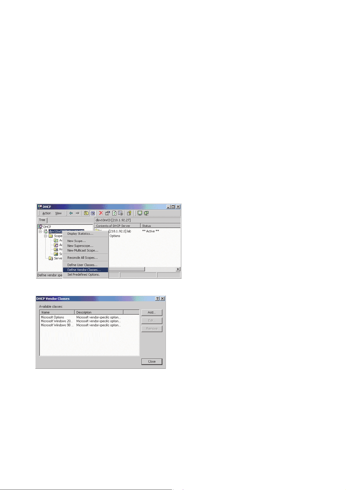
Setting up a new vendor class using the Windows DHCP Server
1. In the Windows Start menu, select Start > Programs > Administrative Tools > DHCP.
2. In the DHCP console menu, right-click the DHCP server in question and select Define
Vendor Classes... in the context menu.
3. A dialog window opens with a list of the classes that are already available.
4. Define a new vendor class with the name OptiIpPhone and enter a description of this
class.
A31003-C1000-M102-5-76A9, 09/2017
28 OpenScape Desk Phone CP200/CP205/CP400/CP600 HFA, Administration Manual
Page 29
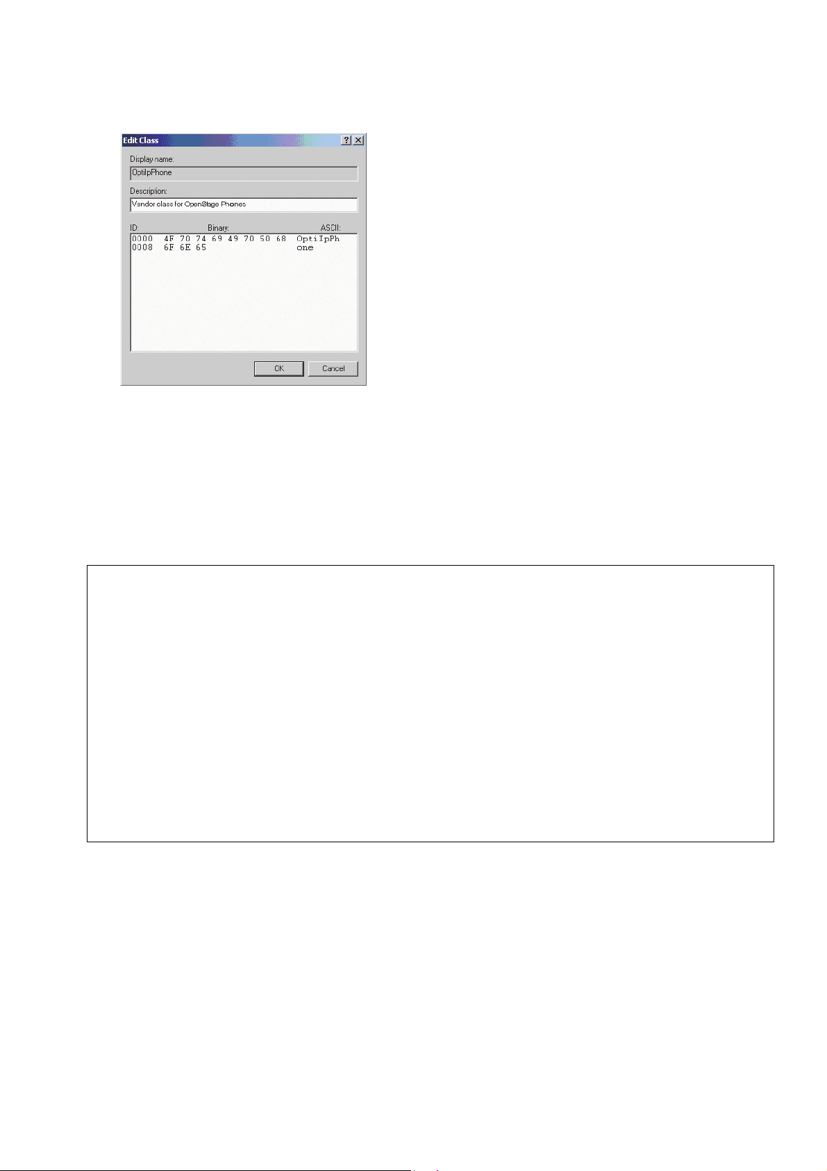
Click OK to apply the changes. The new vendor class now appears in the list.
5. Exit the window with Close.
inbetriebnahme.fm
Startup
Quick Start
Add Options to the New Vendor Class
Next, two options resp. tags will be added to the vendor class. Two passes are needed for this:
in the first pass, tag #1 with the required value "Siemens" is entered, and in the second pass,
the VLAN ID is entered as tag #2.
For DHCP servers on a Windows 2003 Server (pre-SP2):
>
Windows 2003 Server contains a bug that prevents you from using the DHCP console to create an option with the ID 1 for a user-defined vendor class. Instead, this
entry must be created with the netsh tool in the command line (DOS shell).
You can use the following command to configure the required option (without error
message) so that it is also appears later in the DHCP console:
netsh dhcp server add optiondef 1 "Optipoint element 001"
STRING 0 vendor=OptiIpPhone comment="Tag 001 for Optipoint"
The value SIEMENS for optiPoint Element 1 can then be re-assigned over the
DHCP console.
This error was corrected in Windows 2003 Server SP2.
A31003-C1000-M102-5-76A9, 09/2017
OpenScape Desk Phone CP200/CP205/CP400/CP600 HFA, Administration Manual
29
Page 30
inbetriebnahme.fm
Startup
Quick Start
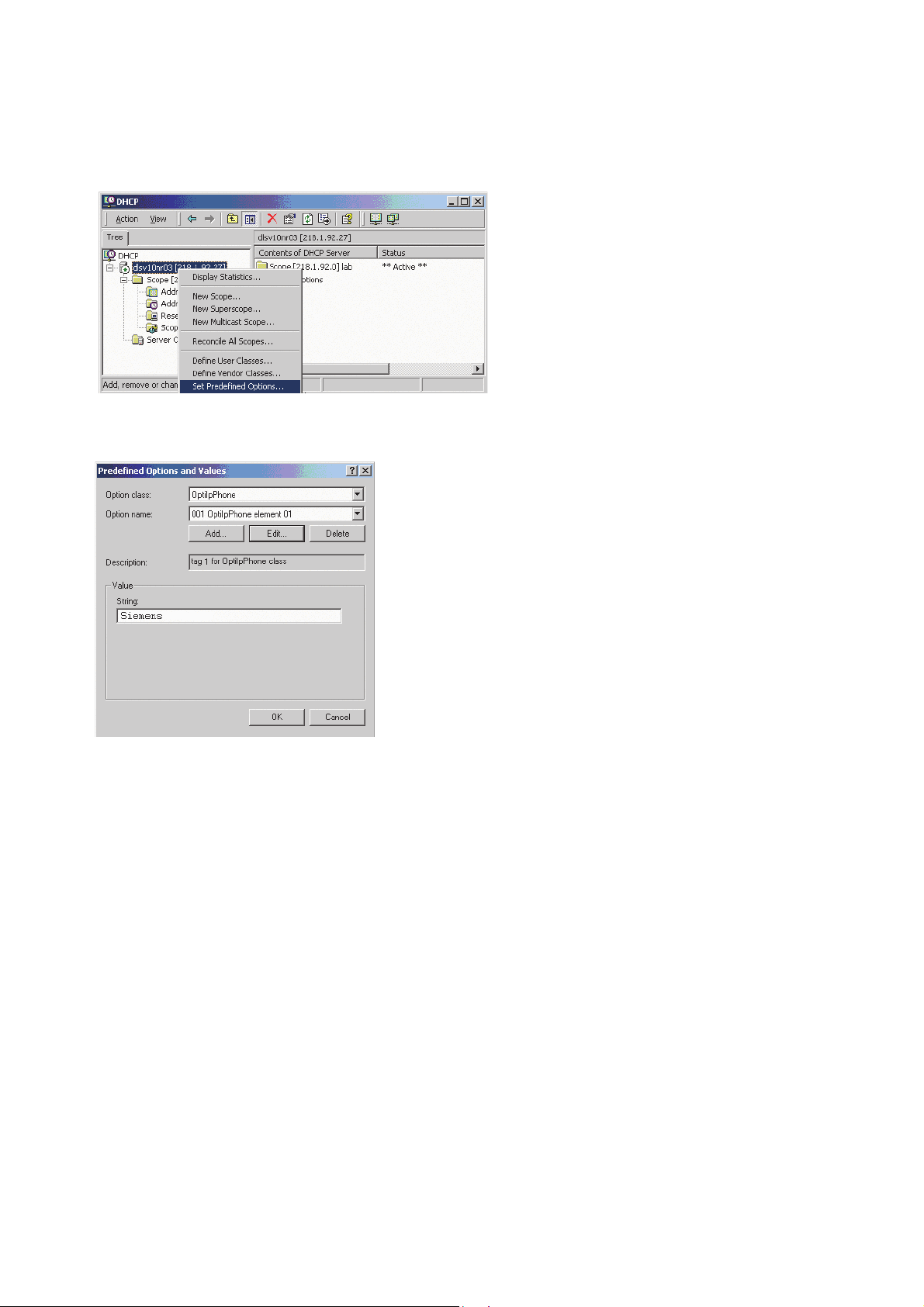
6. In the DHCP console menu, right-click the DHCP server in question and select Set Predefined Options from the context menu.
7. In the dialog, select the previously defined OptiIpPhone class and click on Add... to add
a new option.
A31003-C1000-M102-5-76A9, 09/2017
30 OpenScape Desk Phone CP200/CP205/CP400/CP600 HFA, Administration Manual
Page 31

8. Enter the following data for the new option:
1. First Pass: Option 1
• Name: Free text, e. g. "OptiIpPhone element 01"
• Data type: "String"
• Code: "1"
• Description: Free text.
2. Second Pass: Option 2
• Name: Free text, e. g. "OptiIpPhone element 02"
• Data type: "Long"
• Code: "2"
inbetriebnahme.fm
Startup
Quick Start
• Description: Free text.
9. Enter the value for this option.
1. First Pass: "Siemens"
2. Second Pass: VLAN ID
10. Press OK, repeat steps 7 to 9 for the second pass, and press OK again.
A31003-C1000-M102-5-76A9, 09/2017
OpenScape Desk Phone CP200/CP205/CP400/CP600 HFA, Administration Manual
31
Page 32

inbetriebnahme.fm
Startup
Quick Start
Defining the scope for the new vendor class
11. Select the DHCP server in question and the Scope and right-click Scope Options. Select
Configure Options... in the context menu.
12. Select the Advanced tab. Under Vendor class, select the class that you previously defined (OptiIpPhone) and, under User class, select Default User Class.
Activate the check boxes for the options that you want to assign to the scope (in the example, 001, 002, and 003). Click OK.
13. The DHCP console now shows the information that will be transmitted for the corresponding workpoints. Information from the Standard vendor is transmitted to all clients, whereas
information from the OptiIpPhone vendor is transmitted only to the clients (workpoints) in
this vendor class.
A31003-C1000-M102-5-76A9, 09/2017
32 OpenScape Desk Phone CP200/CP205/CP400/CP600 HFA, Administration Manual
Page 33

inbetriebnahme.fm
Startup
Quick Start
Setup using a DHCP server on Unix/Linux
The following snippet from a DHCP configuration file (usually dhcpd.conf) shows how to set up
a configuration using a vendor class and the "vendor-encapsulated-options" option.
class "OptiIpPhone" {
option vendor-encapsulated-options
# The vendor encapsulated options consist of hexadecimal values for
the option number (for instance, 01), the length of the value (for instance, 07), and the value (for instance, 53:69:65:6D:65:6E:73). The
options can be written in separate lines; the last option must be followed by a ’;’ instead of a ’:’.
# Tag/Option #1: Vendor "Siemens"
#1 7 S i e m e n s
01:07:53:69:65:6D:65:6E:73:
# Tag/Option #2: VLAN ID
#2 4 00 1 0
02:04:00:00:00:0A;
match if substring (option vendor-class-identifier, 0, 11) =
"OptiIpPhone";
}
2.3.8.2 Using Option #43 "Vendor Specific"
Alternatively, option #43 can be used for setting up the VLAN ID. Two tags are required:
• Tag 001: Vendor name
• Tag 002: VLAN ID
The Vendor name tag is coded as follows (the first line indicates the ASCII values, the second
line contains the hexadecimal values):
Code Length Vendor name
17Siemens
01 07 53 69 65 6D 65 6E 73
The following example shows a VLAN ID with the decimal value "10":
Code Length VLAN ID
240010
02 04 00 00 00 0A
For manual configuration of the VLAN ID see Section 3.2.2.1, “Automatic VLAN discovery using
LLDP-MED”.
A31003-C1000-M102-5-76A9, 09/2017
OpenScape Desk Phone CP200/CP205/CP400/CP600 HFA, Administration Manual
33
Page 34

inbetriebnahme.fm
Startup
Quick Start
Setup using the Windows DHCP Server
1. In the Windows Start menu, select Start > Programs > Administrative Tools > DHCP.
2. Select the DHCP server and the scope. Choose "Configure Options" in the context menu
using the right mouse button.
3. Enter the VLAN ID. Providing the length is not required here, as the VLAN ID is always 4
Bytes long.
A31003-C1000-M102-5-76A9, 09/2017
34 OpenScape Desk Phone CP200/CP205/CP400/CP600 HFA, Administration Manual
Page 35

inbetriebnahme.fm
Startup
Quick Start
2.3.9 DLS Server Address
This setting only applies if a DLS (Deployment Service) server is in use.
It is recommended to configure the DLS server address by DCHP, as this method enables full
Plug & Play and ensures the authenticity of the DLS server.
For manual configuration of the DLS server address see Section 3.3.7, “Configuration & Update
Service (DLS)”.
For the configuration of vendor-specific settings by DHCP, there are two alternative methods:
1) the use of a vendor class, or 2) the use of DHCP option 43.
2.3.9.1 Using Vendor Class
It is recommended to define a vendor class on the DHCP server, thus enabling server and
phone to exchange vendor-specific data exclusively. The data is disclosed from other clients. If
not done already, create a vendor class by the name of "OptiIpPhone".
The following steps are required for the configuration of the Windows DHCP server.
Setting up a new vendor class using the Windows DHCP Server
1. In the Windows Start menu, select Start > Programs > Administrative Tools > DHCP.
2. In the DHCP console menu, right-click the DHCP server in question and select Define
Vendor Classes... in the context menu.
A31003-C1000-M102-5-76A9, 09/2017
OpenScape Desk Phone CP200/CP205/CP400/CP600 HFA, Administration Manual
35
Page 36

inbetriebnahme.fm
Startup
Quick Start
3. A dialog window opens with a list of the classes that are already available.
4. Define a new vendor class with the name OptiIpPhone and enter a description of this
class.
Click OK to apply the changes. The new vendor class now appears in the list.
5. Exit the window with Close.
A31003-C1000-M102-5-76A9, 09/2017
36 OpenScape Desk Phone CP200/CP205/CP400/CP600 HFA, Administration Manual
Page 37

inbetriebnahme.fm
Startup
Quick Start
Add Options to the New Vendor Class
Next, two options resp. tags will be added to the vendor class. Two passes are needed for this:
in the first pass, tag #1 with the required value "Siemens" is entered, and in the second pass,
the DLS address is entered as tag #3.
For DHCP servers on a Windows 2003 Server (pre-SP2):
>
6. In the DHCP console menu, right-click the DHCP server in question and select Set Predefined Options from the context menu.
Windows 2003 Server contains a bug that prevents you from using the DHCP console to create an option with the ID 1 for a user-defined vendor class. Instead, this
entry must be created with the netsh tool in the command line (DOS shell).
You can use the following command to configure the required option (without error
message) so that it is also appears later in the DHCP console:
netsh dhcp server add optiondef 1 "Optipoint element 001"
STRING 0 vendor=OptiIpPhone comment="Tag 001 for Optipoint"
The value SIEMENS for optiPoint Element 1 can then be re-assigned over the
DHCP console.
This error was corrected in Windows 2003 Server SP2.
A31003-C1000-M102-5-76A9, 09/2017
OpenScape Desk Phone CP200/CP205/CP400/CP600 HFA, Administration Manual
37
Page 38

inbetriebnahme.fm
Startup
Quick Start
7. In the dialog, select the previously defined OptiIpPhone class and click on Add... to add
a new option.
8. Enter the following data for the new option:
1. First Pass: Option 1
• Name: Free text, e. g. "OptiIpPhone element 01"
• Data type: "String"
• Code: "1"
• Description: Free text.
2. Second Pass: Option 3
• Name: Free text, e. g. "OptiIpPhone element 03"
• Data type: "String"
• Code: "3"
• Description: Free text.
A31003-C1000-M102-5-76A9, 09/2017
38 OpenScape Desk Phone CP200/CP205/CP400/CP600 HFA, Administration Manual
Page 39

9. Enter the value for this option.
1. First Pass: "Siemens"
2. Second Pass: DLS address
The DLS address has the following format:
<PROTOCOL>:://<IP ADDRESS OF DLS SERVER>:<PORT NUMBER>
Example: sdlp://192.168.3.30:18443
inbetriebnahme.fm
Startup
Quick Start
10. Press OK, repeat steps 7 to 9 for the second pass, and press OK again.
Defining the scope for the new vendor class
11. Select the DHCP server in question and the Scope and right-click Scope Options. Select
Configure Options... in the context menu.
A31003-C1000-M102-5-76A9, 09/2017
OpenScape Desk Phone CP200/CP205/CP400/CP600 HFA, Administration Manual
39
Page 40

inbetriebnahme.fm
Startup
Quick Start
12. Select the Advanced tab. Under Vendor class, select the class that you previously defined (OptiIpPhone) and, under User class, select Default User Class.
Activate the check boxes for the options that you want to assign to the scope (in the example, 001 and 003)
13. The DHCP console now shows the information that will be transmitted for the corresponding workpoints. Information from the Standard vendor is transmitted to all clients, whereas
information from the OptiIpPhone vendor is transmitted only to the clients (workpoints) in
this vendor class.
A31003-C1000-M102-5-76A9, 09/2017
40 OpenScape Desk Phone CP200/CP205/CP400/CP600 HFA, Administration Manual
Page 41

inbetriebnahme.fm
Startup
Quick Start
Setup using a DHCP server on Unix/Linux
The following snippet from a DHCP configuration file (usually dhcpd.conf) shows how to set up
a configuration using a vendor class and the "vendor-encapsulated-options" option.
class "OptiIpPhone" {
option vendor-encapsulated-options
# The vendor encapsulated options consist of hexadecimal values for
the option number (for instance, 01), the length of the value (for instance, 07), and the value (for instance, 53:69:65:6D:65:6E:73). The
options can be written in separate lines; the last option must be followed by a ’;’ instead of a ’:’.
# Tag/Option #1: Vendor "Siemens"
#1 7 S i e m e n s
01:07:53:69:65:6D:65:6E:73:
# Tag/Option #3: DLS IP Address (here: sdlp://192.168.3.30:18443)
#3 25sdlp://1 92.168.3. ...etc.
03:19:73:64:6C:70:3A:2F:2F:31:39:32:2E:31:36:38:2E:33:2E:33:30:
3A:31:38:34:34:33;
match if substring (option vendor-class-identifier, 0, 11) =
"OptiIpPhone";
}
A31003-C1000-M102-5-76A9, 09/2017
OpenScape Desk Phone CP200/CP205/CP400/CP600 HFA, Administration Manual
41
Page 42

inbetriebnahme.fm
Startup
Quick Start
2.3.9.2 Using Option #43 "Vendor Specific"
Alternatively, option #43 can be used for setting up the DLS address. Two tags are required:
• Tag 001: Vendor name
• Tag 003: DLS IP address
Additionally, you can enter a host name for the DLS server:
• Tag 004: DLS hostname
The data is entered in hexadecimal values. Note that the length of the information contained in
a tag must be given.
The Vendor name tag is coded as follows (the first line indicates the ASCII values, the second
line contains the hexadecimal values):
Code Length Vendor name
17Siemens
01 07 53 69 65 6D 65 6E 73
The DLS IP address tag consists of the protocol prefix "sdlp://", the IP address of the DLS server, and the DLS port number, which is "18443" by default. The following example illustrates the
syntax:
Code Length DLS IP address
3 25 sdl p: / / 192. 168. 2. 19: 18443
03 19
73646C703A2F2F3139322E3136382E322E31393A3138343433
A31003-C1000-M102-5-76A9, 09/2017
42 OpenScape Desk Phone CP200/CP205/CP400/CP600 HFA, Administration Manual
Page 43

inbetriebnahme.fm
Startup
Quick Start
Setup using the Windows DHCP Server
1. In the Windows Start menu, select Start > Programs > Administrative Tools > DHCP.
2. Select the DHCP server and the scope. Choose "Configure Options" in the context menu
using the right mouse button. [Engl. Screenshot]
3. Enter the IP address and port number of the DLS server.
A31003-C1000-M102-5-76A9, 09/2017
OpenScape Desk Phone CP200/CP205/CP400/CP600 HFA, Administration Manual
43
Page 44

inbetriebnahme.fm
Startup
Quick Start
2.3.10 HFA Gateway Settings
To connect the OpenScape Desk Phone CP phone to the OpenScape Business or OpenScape
4000 Communication System, the IP address of the gateway, a subscriber number and the corresponding password is needed. The subscriber number can be 1 to 24 characters long, and
is used as the internal telephone number.
2.3.11 Using the Web Interface (WBM)
1. Log in to the Administrator Pages of the WBM. For details about accessing the WBM, see
Section 2.3.1, “How to Access the Web Interface (WBM)”.
2. In the menu at the lefthand side, go to System > Gateway.
3. Enter the IP address of the OpenScape Business or OpenScape 4000 Communication
System in the IP address field.
4. In the Subscriber number field, enter the internal extension number of the phone. It can
be 1 to 24 characters long.
5. Enter the subscriber password in the Password field.
2.3.12 Using the Local Menu
Take the following steps to configure the access to an HFA gateway (for further information see
Section 2.3.2, “Access via Local Phone”):
1. In the administration menu, go to System > Gateway. For further instructions on entering
data using the Local menu see Section 2.3.2, “Access via Local Phone”. The path is as
follows:
|
--- Administration
|
--- System
|
--- Gateway
|--- System type
|--- IP address
|--- Gateway ID
|--- Subscriber number
|
--- Password
2. Enter the IP address of the HFA gateway provided by your OpenScape Communication
System.
3. Enter the phone’s Gateway Id, which will also serve as internal phone number.
4. Enter the password associated with the Gateway Id.
After the data has been entered, select Save & exit and press .
A31003-C1000-M102-5-76A9, 09/2017
44 OpenScape Desk Phone CP200/CP205/CP400/CP600 HFA, Administration Manual
Page 45

administration.fm
Server Address
Server Port
Zone
Off
Disabled
Localization client
Submit
Reset
Bluetooth
Enable Bluetooth interface
;
Feature Access
Enable
Administration
Bluetooth Interface
3 Administration
This chapter describes the configuration of every parameter available on the OpenScape Desk
Phone CP phones. Please refer to Section 2.3.1, “How to Access the Web Interface (WBM)”.
3.1 Bluetooth Interface
Bluetooth is available only on Open Scape Desk Phone CP600.
>
3.1.1 Feature Access
You can activate and deactivate the Bluetooth interface. If the Bluetooth interface is deactivated
no Bluetooth services are available.
Administration via WBM
Bluetooth
Administration via Local Phone
|
--- Bluetooth
A31003-C1000-M102-5-76A9, 09/2017
OpenScape Desk Phone CP200/CP205/CP400/CP600 HFA, Administration Manual
45
Page 46

administration.fm
Administration
LAN Settings
3.2 LAN Settings
3.2.1 LAN Port Settings
The OpenScape Desk Phone CP200/205/400/600 phone provides an integrated switch which
connects the LAN, the phone itself and a PC port. By default, the switch will auto negotiate
transfer rate (10/100/1000 Mb/s autosensing, configurable, Gigabit not available on
OpenScape Desk Phone CP200) and duplex method (full or half duplex) with whatever equipment is connected. Optionally, the required transfer rate and duplex mode can be specified
manually using the LAN Port Speed parameter.
In the default configuration, the LAN port supports automatic detection of cable con-
>
figuration (pass through or crossover cable) and will reconfigure itself as needed to
connect to the network. If the phone is set up to manually configure the switch port
settings, the cable detection mechanism is disabled. In this case care must be taken
to use the correct cable type.
The PC Ethernet port (default setting: Disabled) is controlled by the PC port mode parameter.
If set to "Disabled", the PC port is inactive; if set to "Enabled", it is active. If set to "Mirror", the
data traffic at the LAN port is mirrored at the PC port. This setting is for diagnostic purposes. If,
for instance, a PC running Ethereal/Wireshark is connected to the PC port, all network activities
at the phone’s LAN port can be captured.
Do not use this connection for further OpenScape Desk Phone CP or OpenStage
>
>
When PC port autoMDIX is enabled, the switch determines automatically whether a regular
MDI connector or a MDI-X (crossover) connector is needed, and configures the connector accordingly.
Data required
phones!
Removing the power from the phone or a phone reset/reboot will result in the temporary loss of the network connection to the PC port.
• LAN port speed: Settings for the ethernet port connected to a LAN switch.
Value range: "Automatic," "10 Mbps half duplex", "10 Mbps full duplex", "100 Mbps half duplex", "100 Mbps full duplex", "1 Gbps full duplex" (OpenScape Desk Phone CP205, OpenScape Desk Phone CP400 and OpenScape Desk Phone CP600 only) .
Default: "Automatic"
A31003-C1000-M102-5-76A9, 09/2017
46 OpenScape Desk Phone CP200/CP205/CP400/CP600 HFA, Administration Manual
Page 47

administration.fm
System H.225
Standby H.225
System Cornet TLS
Standby Cornet TLS
System H.225 TLS
Standby H.225 TLS
1300
Port configuration
1720
4061
RTP base
5004
1300
1720
4061
Gateway
Standby gateway
4060
4060
LAN port speed
Automatic
Submit
Reset
Automatic
PC port speed
PC port autoMDIX
disabled
PC port mode
LDAP server
HTTP proxy
389
0
Administration
LAN Settings
• PC port speed / PC port type: Settings for the ethernet port connected to a PC.
Value range: "Automatic," "10 Mbps half duplex", "10 Mbps full duplex", "100 Mbps half duplex", "100 Mbps full duplex", "1 Gbps full duplex" (OpenScape Desk Phone CP205, OpenScape Desk Phone CP400 and OpenScape Desk Phone CP600 only).
Default: "Automatic"
• PC port mode / PC port status: Controls the PC port.
Value range: "disabled", "enabled", "mirror".
Default: "disabled"
• PC port autoMDIX: Switches between MDI and MDI-X automatically.
Value range: "On", "Off"
Default: "Off"
Administration via WBM
Network > Port configuration
Administration via Local Phone
|
--- Admin
A31003-C1000-M102-5-76A9, 09/2017
OpenScape Desk Phone CP200/CP205/CP400/CP600 HFA, Administration Manual
|
--- Network
|
--- Port Configuration
|
--- Number
|--- LAN port speed
|--- PC port status
|--- PC port speed
|
--- PC port autoMDIX
47
Page 48

administration.fm
Administration
LAN Settings
3.2.2 VLAN
VLAN (Virtual Local Area Network) is a technology that allows network administrators to partition one physical network into a set of virtual networks (or broadcast domains).
Partitioning a physical network into separate VLANs allows a network administrator to build a
more robust network infrastructure. A good example is a separation of the data and voice networks into data and voice VLANs. This isolates the two networks and helps shield the endpoints
within the voice network from disturbances in the data network and vice versa.
The implementation of a voice network based on VLANs requires the network infra-
>
In a layer 1 VLAN, the ports of a VLAN-aware switch are assigned to a VLAN statically. The
switch only forwards traffic to a particular port if that port is a member of the VLAN that the traffic
is allocated to. Any device connected to a VLAN-assigned port is automatically a member of
this VLAN, without being a VLAN aware device itself. If two or more network clients are connected to one port, they cannot be assigned to different VLANs. When a network client is moving from one switch to another, the switches’ ports have to be updated accordingly by hand.
structure (the switch fabric) to support VLANs.
With a layer 2 VLAN, the assignment of VLANs to network clients is realized by the MAC addresses of the network devices. In some environments, the mapping of VLANs and MAC addresses can be stored and managed by a central database. Alternatively, the VLAN ID, which
defines the VLAN whereof the device is a member, can be assigned directly to the device, e. g.
by DHCP. The task of determining the VLAN for which an Ethernet packet is destined is carried
out by VLAN tags within each Ethernet frame. As the MAC addresses are (more or less) wired
to the devices, mobility does not require any administrator action, as opposed to layer 1 VLAN.
The phone must be configured as a VLAN aware endpoint if the phone itself is a member of the
voice VLAN, and the PC connected to the phone’s PC port is a member of the data VLAN.
There are 3 ways for configuring the VLAN ID:
• By LLDP-MED
• By DHCP
• Manually
3.2.2.1 Automatic VLAN discovery using LLDP-MED
This is the default setting. The VLAN ID is configured by the network switch using LLDP-MED
(Link Layer Discovery Protocol-Media Endpoint Discovery). If the switch provides an appropriate TLV (Type-Length-Value) element containing the VLAN ID, this VLAN ID will be used. If no
appropriate TLV is received, DHCP will be used for VLAN discovery.
A31003-C1000-M102-5-76A9, 09/2017
48 OpenScape Desk Phone CP200/CP205/CP400/CP600 HFA, Administration Manual
Page 49

administration.fm
Administration
LAN Settings
Administration via WBM
Network > General IP configuration
First, click on change mode. Afterwards, the IP configuration mode dialog opens.
Administration via Local Phone
To enable VLAN discovery via LLDP-MED, set the Use LLDP-MED option to Yes and select
LLDP-MED in the VLAN discovery option.
|
--- Administration
|
--- Network
|
--- General IP configuration
|--- Protocol Mode
|--- LLDP-MED enabled
|--- DHCP enabled
|--- VLAN discovery
|--- VLAN ID
|
--- DNS domain
|
--- Primary DNS
|
--- Secondary DNS
|
--- HTTP proxy
3.2.2.2 Automatic VLAN discovery using DHCP
To automatically discover a VLAN ID using DHCP, the phone must be configured as DHCP enabled, and VLAN discovery mode must be set to "DHCP". LLDPMED should be disabled. The
DHCP server must be configured to supply the Vendor Unique Option in the correct VLAN over
DHCP format. If a phone configured for VLAN discovery by DHCP fails to discover its VLAN, it
will proceed to configure itself from the DHCP within the non-tagged LAN. Under these circumstances, network routing may probably not be correct.
A31003-C1000-M102-5-76A9, 09/2017
OpenScape Desk Phone CP200/CP205/CP400/CP600 HFA, Administration Manual
49
Page 50

administration.fm
Administration
LAN Settings
Administration via WBM
Network > General IP configuration
To enable VLAN discovery via LLDP-MED, activate the LLDP-MED Enabledcheckbox and select LLDP-MED in the VLAN discovery option. Afterwards, click Submit.
Administration via Local Phone
To enable VLAN discovery via DHCP, activate the DHCP Enabled checkbox and select DHCP
in the VLAN discovery option.
|
--- Administration
|
--- Network
|
--- General IP configuration
|--- Protocol Mode
|--- LLDP-MED enabled
|--- DHCP enabled
|--- VLAN discovery
|--- VLAN ID
|
--- DNS domain
|
--- Primary DNS
|
--- Secondary DNS
|
--- HTTP proxy
3.2.2.3 Manual configuration of a VLAN ID
To configure layer 2 VLAN manually, first make sure that VLAN discovery is set to "Manual" (see
Section 3.2.2.1, “Automatic VLAN discovery using LLDP-MED”). Then, the phone must be provided with a VLAN ID between 1 and 4095. If you misconfigure a phone to an incorrect VLAN,
the phone will possibly not connect to the network. In DHCP mode it will behave as though the
DHCP server cannot be found, in fixed IP mode no server connections will be possible.
A31003-C1000-M102-5-76A9, 09/2017
50 OpenScape Desk Phone CP200/CP205/CP400/CP600 HFA, Administration Manual
Page 51

administration.fm
Administration
LAN Settings
Administration via WBM
The phone must be provided with a VLAN Id between 1 and 4095. Set the VLAN discovery to
Manual. Afterwards, click Submit.
Network > General IP configuration
Administration via Local Phone
|
--- Administration
|
--- Network
|
--- General IP configuration
|--- Protocol Mode
|--- LLDP-MED enabled
|--- DHCP enabled
|--- VLAN discovery
|--- VLAN ID
|
--- DNS domain
|
--- Primary DNS
|
--- Secondary DNS
|
--- HTTP proxy
A31003-C1000-M102-5-76A9, 09/2017
OpenScape Desk Phone CP200/CP205/CP400/CP600 HFA, Administration Manual
51
Page 52

administration.fm
Administration
IP Network Parameters
3.3 IP Network Parameters
3.3.1 Quality of Service (QoS)
The QoS technology based on layer 2 and the two QoS technologies Diffserv and TOS/IP Precedence based on layer 3 are allowing the VoIP application to request and receive predictable
service levels in terms of data throughput capacity (bandwidth), latency variations (jitter), and
delay.
Layer 2 and 3 QoS for voice transmission can be set via LLDP-MED (see LLDP-
>
3.3.1.1 Layer 2 / 802.1p
QoS on layer 2 is using 3 Bits in the 802.1q/p 4-Byte VLAN tag which has to be added in the
Ethernet header.
MED). If so, the value can not be changed by any other interface.
The CoS (class of service) value can be set from 0 to 7. 7 is describing the highest priority and
is reserved for network management. 5 is used for voice (RTP-streams) by default. 3 is used
for signaling by default.
PREAM. SFD DA SA
TAG
4 Bytes
Three Bits Used for CoS
PT DATA FCS
(User Priority)
Data required
• Layer 2: Activates or deactivates QoS on layer 2.
Value range: "Yes", "No"
Default: "Yes"
• Layer 2 voice: Sets the CoS (Class of Service) value for voice data (RTP streams).
Value range: 0-7
Default: 5
• Layer 2 signalling: Sets the CoS (Class of Service) value for signaling.
Value range: 0-7
Default: 3
• Layer 2 default: Sets the default CoS (Class of Service) value.
Value range: 0-7
Default: 0
A31003-C1000-M102-5-76A9, 09/2017
52 OpenScape Desk Phone CP200/CP205/CP400/CP600 HFA, Administration Manual
Page 53

Administration via WBM
Layer 2 signalling
Layer 2 default
Layer 3 voice
Layer 3 signalling
Layer 2 voice
Layer 2
5
0
QoS
3
Layer 3
EF
AF31
;
Network > QoS
Administration via Local Phone
|
--- Admin
|
--- Network
|
--- QoS
|
--- Service
|--- Layer 2
|--- Layer 2 voice
|--- Layer 2 signalling
|
--- Layer 2 default
administration.fm
Administration
IP Network Parameters
3.3.1.2 Layer 3 / Diffserv
Diffserv assigns a class of service to an IP packet by adding an entry in the IP header.
Traffic flows are classified into 3 per-hop behavior groups:
1. Default
Any traffic that does not meet the requirements of any of the other defined classes is placed
in the default per-hop behaviour group. Typically, the forwarding has best-effort forwarding
characteristics. The DSCP (Diffserv Codepoint) value for Default is "0 0 0000".
2. Expedited Forwarding (EF referred to RFC 3246)
Expedited Forwarding is used for voice (RTP streams) by default. It effectively creates a
special low-latency path in the network. The DSCP (Diffserv Codepoint) value for EF is
"101110".
3. Assured Forwarding (AF referred to RFC 2597)
Assured forwarding is used for signaling messages by default (AF31). It is less stringent
than EF in a multiple dropping system. The AF values are containing two digits X and Y
(AFXY), where X is describing the priority class and Y the drop level.
Four classes X are reserved for AFXY: AF1Y (low priority), AF2Y, AF3Y and AF4Y (high
priority).
A31003-C1000-M102-5-76A9, 09/2017
OpenScape Desk Phone CP200/CP205/CP400/CP600 HFA, Administration Manual
53
Page 54

administration.fm
Layer 2 signalling
Layer 2 default
Layer 3 voice
Layer 3 signalling
Layer 2 voice
Layer 2
5
0
QoS
3
Layer 3
;
EF
AF31
Administration
IP Network Parameters
Three drop levels Y are reserved for AFXY: AFX1 (low drop probability), AFX2 and AFX3
(High drop probability). In the case of low drop level, packets are buffered over an extended
period in the case of high drop level, packets are promptly rejected if they cannot be forwarded.
Data required
• Layer 3: Activates or deactivates QoS on layer 3.
Value range: "Yes", "No"
Default: "Yes"
• Layer 3 voice: Sets the CoS (Class of Service) value for voice data (RTP streams).
Value range: "BE", "AF11", "AF12", "AF13", "AF21", "AF22", "AF23", "AF31", "AF32",
"AF33", "AF41", "AF42", "AF43", "EF", "CS7", "CS3", "CS4", "CS5", 0, 1, 2 ... through 63.
Default: "EF"
• Layer 3 signalling: Sets the CoS (Class of Service) value for signaling.
Value range: "BE", "AF11", "AF12", "AF13", "AF21", "AF22", "AF23", "AF31", "AF32",
"AF33", "AF41", "AF42", "AF43", "EF", "CS7", "CS3", "CS4", "CS5", 0, 1, 2 ... through 63.
Default: "AF31"
Administration via WBM
Network > QoS
Administration via Local Phone
|
--- Admin
|
--- Network
|
--- QoS
|
--- Service
|--- Layer 3
|--- Layer 3 voice
|
--- Layer 3 signalling
A31003-C1000-M102-5-76A9, 09/2017
54 OpenScape Desk Phone CP200/CP205/CP400/CP600 HFA, Administration Manual
Page 55

administration.fm
LLDP-MED enabled
DNS domain
Primary DNS
Secondary DNS
General IP configuration
osbiz
DHCP enabled
Submit
Reset
VLAN discovery
VLAN ID
Protocol mode
IPv4
DHCP
8.8.8.8
;
;
Administration
IP Network Parameters
3.3.2 Use DHCP
If this parameter is set to "Yes" (default), the phone will search for a DHCP server on startup
and try to obtain IP data and further configuration parameters from that central server.
If no DHCP server is available in the IP network, please deactivate this option. In this case, the
IP address, subnet mask and default gateway/route must be defined manually.
The change will only have effect if you restart the phone.
>
The following parameters can be obtained by DHCP:
Basic Configuration
• IP Address
• Subnet Mask
The phone is able to maintain its IP connection even in case of DHCP server failure.
For further information, please refer to DHCP Resilience.
Optional Configuration
• Default Route (Routers option 3)
• IP Routing/Route 1 & 2 (Static Routes option 33), Classless static route option 121, Provate/Classless Static Rout (Microsoft) option 249)
• Primary/Secondary DNS (DNS Server option 6)
• DNS Domain Name (DNS Domain option 15)
• SNTP IP Address (NTP Server option 42)
• Timezone offset (Time Server Offset option 2)
• VLAN ID, DLS address (Vendor specific Information option 43)
Administration via WBM
Network > General IP configuration
A31003-C1000-M102-5-76A9, 09/2017
OpenScape Desk Phone CP200/CP205/CP400/CP600 HFA, Administration Manual
55
Page 56

administration.fm
Administration
IP Network Parameters
Administration via Local Phone
|
--- Admin
|
--- Network
|
--- General IP Configuration
|
--- DHCP enabled
A31003-C1000-M102-5-76A9, 09/2017
56 OpenScape Desk Phone CP200/CP205/CP400/CP600 HFA, Administration Manual
Page 57

administration.fm
LLDP-MED Enabled
IP address
Subnet mask
Default route
Route 1 IP address
IPv4 configuration
255.255.255.0
DHCP Enabled
Submit
Reset
192.168.1.105
Route 2 mask
Route 1 gateway
Route 1 mask
Route 2 IP address
Route 2 gateway
192.168.1.2
;
DHCP lease reuse
Administration
IP Network Parameters
3.3.3 IP Address - Manual Configuration
If not provided by DHCP dynamically, you must specify the phone’s IP address and subnet
mask manually.
Data required
• IP address: used for addressing the phone.
• Subnet mask: subnet mask that is needed for the subnet in use.
Administration via WBM
Network > IPv4 configuration
Administration via Local Phone
A31003-C1000-M102-5-76A9, 09/2017
OpenScape Desk Phone CP200/CP205/CP400/CP600 HFA, Administration Manual
|
--- Admin
|
--- Network
|
--- IPv4 Configuration
|--- IP address
|
--- Subnet mask
57
Page 58

administration.fm
LLDP-MED Enabled
IP address
Subnet mask
Default route
Route 1 IP address
IPv4 configuration
255.255.255.0
DHCP Enabled
Submit
Reset
192.168.1.105
Route 2 mask
Route 1 gateway
Route 1 mask
Route 2 IP address
Route 2 gateway
192.168.1.2
;
DHCP lease reuse
Administration
IP Network Parameters
3.3.4 Default Route/Gateway
If not provided by DHCP dynamically (see Section 3.3.2, “Use DHCP”), enter the IP address of
the router that links your IP network to other networks. If the value was assigned by DHCP, it
can only be read.
The change will only have effect if you restart the phone.
>
Administration via WBM
Network > IPv4 configuration
Administration via Local Phone
|
--- Admin
|
--- Network
|
--- IPv4 Configuration
|
--- Default route
58 OpenScape Desk Phone CP200/CP205/CP400/CP600 HFA, Administration Manual
A31003-C1000-M102-5-76A9, 09/2017
Page 59

administration.fm
LLDP-MED Enabled
IP address
Subnet mask
Default route
Route 1 IP address
IPv4 configuration
255.255.255.0
DHCP Enabled
Submit
Reset
192.168.1.105
Route 2 mask
Route 1 gateway
Route 1 mask
Route 2 IP address
Route 2 gateway
192.168.1.2
;
DHCP lease reuse
Administration
IP Network Parameters
3.3.5 Specific IP Routing
To have constant access to network subscribers of other domains, you can enter a total of two
more network destinations, in addition to the default route/gateway. This is useful if the LAN has
more than one router or if the LAN is divided into subnets.
Data required
• Route 1/2 IP address: IP address of the selected route.
• Route 1/2 gateway: IP address of the gateway for the selected route.
• Route 1/2 mask: Network mask for the selected route.
Administration via WBM
Network > IPv4 configuration
Administration via Local Phone
A31003-C1000-M102-5-76A9, 09/2017
OpenScape Desk Phone CP200/CP205/CP400/CP600 HFA, Administration Manual
|
--- Admin
|
--- Network
|
--- IPv4 Configuration
|--- Route 1 IP
|--- Route 1 gateway
|--- Route 1 mask
|--- Route 2 IP
|--- Route 2 gateway
|
--- Route 2 mask
59
Page 60

administration.fm
LLDP-MED enabled
DNS domain
Primary DNS
Secondary DNS
General IP configuration
osbiz
DHCP enabled
Submit
Reset
VLAN discovery
VLAN ID
Protocol mode
IPv4
DHCP
8.8.8.8
;
;
Administration
IP Network Parameters
3.3.6 DNS
The main task of the domain name system (DNS) is to translate domain names to IP addresses. For some features and functions of the OpenScape Desk Phone CP phone, it is necessary
to configure the DNS domain the phone belongs to, as well as the name servers needed for
DNS resolving.
3.3.6.1 DNS Domain Name
This is the name of the phone’s local domain.
Administration via WBM
Network > General IP configuration
Administration via Local Phone
|
--- Admin
|
--- Network
|
--- General IP configuration
|
--- DNS domain
60 OpenScape Desk Phone CP200/CP205/CP400/CP600 HFA, Administration Manual
A31003-C1000-M102-5-76A9, 09/2017
Page 61

administration.fm
System Identity
Terminal number
Web name
Submit
Reset
3338
DNS name construction
Only number
Administration
IP Network Parameters
3.3.6.2 Terminal Hostname
The phone’s hostname can be customised.
DHCP and DNS must be appropriately connected and configured at the customer
>
site.
The corresponding DNS domain is configured in Network > IP configuration > DNS domain
(see Section 3.3.6.1, “DNS Domain Name”).
The current DNS name of the phone is displayed at the right-hand side of the banner of the
admin and user web pages, under DNS name. To see configuration changes, the web page
must be reloaded.
It is recommended to inform the user about the DNS name of the phone. The
>
complete WBM address can be found under User menu > Network information >
Web address.
The DNS name can be constructed from pre-defined parameters and free text. Its composition
is defined by the DNS name construction parameter. The following options are available:
• "None": No hostname is send to the DHCP server during DHCP configuration.
• "MAC based": The DNS name is built from the prefix "OIP" followed by the phone’s MAC
address.
• "Web name": The DNS name is set to the the string entered in Web name.
• "Only number": The DNS name is set to the Terminal number, that is, the phone’s call
number (E.164).
• "Prefix number": The DNS name is constructed from the the string entered in Web name,
followed by the Terminal number.
Administration via WBM
System > System Identity
Administration via Local Phone
|
--- Administration
A31003-C1000-M102-5-76A9, 09/2017
OpenScape Desk Phone CP200/CP205/CP400/CP600 HFA, Administration Manual
|
--- Identity
|--- Web name
|
--- DNS hostname
61
Page 62

administration.fm
Administration
IP Network Parameters
3.3.7 Configuration & Update Service (DLS)
The additional WBM and DLI are alternative administration tools. DLI uses the same
>
The OpenScape Deployment Service (DLS) is a OpenScape Management Application for administering workpoints. Amongst the most important features are: security (e.g. PSS generation and distribution within an SRTP security domain), mobility for OpenScape phones, software deployment, plug&play support, as well as error and activity logging.
DLS address, i.e. the IP address or hostname of the DLS server, and Default mode port, i.e.
the port on which the DLS server is listening, are required to enable proper communication between phone and DLS. The Contact gap parameter controls a security function. It specifies a
minimum time interval that must elapse between individual HTTP requests from the phone
which are responding to a ContactMe request from the DLS. Any requests coming within that
time will be ignored. The purpose is to prevent DoS (Denial of Service) attacks on the phone.
Set Revert to default security to disable mutual authentication and return to DEFAULT mode.
SECURE mode related settings are reset and certificates are removed.
technical inferface like DLS, but with less functionality.
The Mode determines whether the communication between the phone and the DLS is secure.
A secure connection is established by exchanging credentials between the DLS and the phone
for mutual authentication. After this, the communication is encrypted, and a different port is
used.
It is possible to operate the DLS server behind a firewall or NAT (Network Address
>
>
A Security PIN can be provided which is used for decrypting data provided by the DLS during
bootstrap. For further information, please refer to the DLS documentation.
Translation), which prevents the DLS from sending Contact-Me messages directly to
the phone. Only outbound connections from the phone are allowed. To overcome
this restriction, a DLS Contact-Me proxy (DCMP) can be deployed. The phone periodically polls the DCMP (DLS Contact- Me Proxy), which is placed outside of the
phone’s network, for pending contact requests from the DLS. If there are contact requests, the phone will send a request to the DLS in order to obtain the update, just
as with a regular DLS connection.
The URI of the DCMP, as well as the polling interval, are configured by the DLS. For
this purpose, it is necessary that the phone establishes a first contact to the DLS,
e. g. by phone restart or local configuration change.
A31003-C1000-M102-5-76A9, 09/2017
62 OpenScape Desk Phone CP200/CP205/CP400/CP600 HFA, Administration Manual
Page 63

administration.fm
Update service (DLS)
DLS address
Default mode port
Submit
Reset
192.168.1.10
Mode
Default
Contact gap
300
18443
Security PIN
300
Revert to default security
Administration
IP Network Parameters
Data required
• DLS address: IP address or hostname of the server on which the Deployment Service is
running.
• Default mode port: Port on which the DLS Deployment Service is listening.
Default: 18443.
• Revert to default security: When set, security mode will be set to default. When using
local phone administration, this will be set by selection option ’Default security’ after pressing Save&exit.
• Contact gap: Minimum time interval in seconds that must elapse between responses to a
ContactMe request from the DLS, in order to prevent DoS attacks.
Default: 300.
• Mode: Determines whether the communication between the phone and the DLS is secure.
Value range: "Default", "Secure".
Default: "Default".
• Security PIN: Used for enhanced security.
Administration via WBM
Network > Update Service (DLS)
Administration via Local Phone
|
--- Admin
|
--- Network
|
--- Update service (DLS)
|--- DLS address
|--- Default mode port
|--- Revert to default security
|--- Contact gap
|--- Mode
|
--- Security PIN
A31003-C1000-M102-5-76A9, 09/2017
OpenScape Desk Phone CP200/CP205/CP400/CP600 HFA, Administration Manual
63
Page 64

administration.fm
Administration
IP Network Parameters
3.3.8 SNMP
The Simple Network Management Protocol is used by network management systems for monitoring network-attached devices for conditions that warrant administrative attention. An SNMP
manager surveys and, if needed, configures several SNMP elements, e.g. VoIP phones.
OpenScape Desk Phone CP phones support SNMPv1.
There are currently 4 trap categories that can be sent by the phones:
Standard SNMP traps
OpenScape Desk Phone CP phones support the following types of standard SNMP traps, as
defined in RFC 1157:
• coldStart: sent if the phone does a full restart.
• warmStart: sent if only the phone software is restarted.
• linkUp: sent when IP connectivity is restored.
QoS Related traps
These traps are designed specifically for receipt and interpretation by the QDC collection system. The traps are common to SIP phones, HFA phones, Gateways, etc.
Traps specific to OpenScape Desk Phone CP phones
Currently, the following traps are defined:
TraceEventFatal: sent if severe trace events occur; aimed at expert users.
TraceEventError: sent if severe trace events occur; aimed at expert users.
Data required
• Trap sending enabled: Enables or disables the sending of a TRAP message to the SNMP
manager.
Value range: "Yes", "No"
Default: "No"
• Trap destination: IP address or hostname of the SNMP manager that receives traps.
• Trap destination port: Port on which the SNMP manager is receiving TRAP messages.
• Default: 162
• Trap community: SNMP community string for the SNMP manager receiving TRAP messages.
Default: "snmp"
• Queries allowed: Allows or disallows queries by the SNMP manager.
• Query password: Password for the execution of a query by the SNMP manager.
A31003-C1000-M102-5-76A9, 09/2017
64 OpenScape Desk Phone CP200/CP205/CP400/CP600 HFA, Administration Manual
Page 65

administration.fm
Administration
IP Network Parameters
• Diagnostic sending enabled: Enables or disables the sending of diagnostic data to the
SNMP manager.
Value range: "Yes", "No"
Default: "No"
• Diagnostic destination: IP address or hostname of the SNMP manager receiving diagnostic data.
• Diagnostic destination port: Port on which the SNMP manager is receiving diagnostic
data.
• Diagnostic community: SNMP community string for the SNMP manager receiving diagnostic data.
• Diagnostic to generic destination: Enables or disables the sending of SNMP traps to a
generic destination.
Value range: "Yes", "No"
Default: "No"
• QoS traps to QCU: Enables or disables the sending of TRAP messages to the QCU server.
Value range: "Yes", "No"
Default: "No"
• QCU address: IP address or hostname of the QCU server.
• QCU port: Port on which the QCU server is listening for messages.
Default: 12010.
• QCU community: QCU community string.
Default: "QOSCD".
• QoS to generic destination: Enables or disables the sending of QoS traps to a generic
destination.
Value range: "Yes", "No"
Default: "No"
A31003-C1000-M102-5-76A9, 09/2017
OpenScape Desk Phone CP200/CP205/CP400/CP600 HFA, Administration Manual
65
Page 66

administration.fm
Traping sending enabled
Trap destination
Trap destination port
Trap community
Queries allowed
Query password
SNMP
QoS report traps
Diagnostic traps
Generic traps
****
Diagnostic sending enabled
Diagnostic destination
Diagnostic destination port
Diagnostic community
Diagnostic to generic destination
Submit
Reset
162
QoS traps to QCU
QCU address
QCU port
12010
QCU community
QoS to generic destination
*****
Administration
IP Network Parameters
Administration via WBM
System > SNMP
Administration via Local Phone
|
--- Admin
|
--- System
|
--- SNMP
66 OpenScape Desk Phone CP200/CP205/CP400/CP600 HFA, Administration Manual
|--- Queries allowed
|--- Query password
|--- Traps enabled
|--- Manager address
|--- Manager port
|--- Community pwd
|--- Diag sending enabled
|--- Diag destination
|--- Diag destination port
|--- Diag community
|--- QoS traps to QCU
|--- QCU address
|--- QCU port
|--- QCU community
|
--- QoS to generic dest.
A31003-C1000-M102-5-76A9, 09/2017
Page 67

administration.fm
Administration
OpenScape Service Menu
3.4 OpenScape Service Menu
The phone’s local menu allows for controlling functions provided the OpenScape system. For
this purpose, the phone must be logged on at the system. For information on the available functions, see the phone’s user manual.
Administration via Local Phone
|
--- Service Menu
A31003-C1000-M102-5-76A9, 09/2017
OpenScape Desk Phone CP200/CP205/CP400/CP600 HFA, Administration Manual
67
Page 68

administration.fm
Gateway
System type
IP address
Gateway ID
DEFAULTH232ID
192.168.1.2
Subscriber number
101
Submit
Reset
OpenScape Business V1
Password
*****
Administration
System Settings
3.5 System Settings
3.5.1 System Identity
3.5.2 HFA Gateway Settings
To connect the OpenScape Desk Phone CP phone to the OpenScape System, the data described in the following are required.
The Gateway address is the IP address of the communication platform resp. HFA server.
The Gateway port is the port used by the HFA server for signaling messages. Usually, the de-
fault value "4060" is correct.
The Subscriber number is used as the internal extension number of the phone. It can be 1 to
24 characters long.
To log on to the HFA server, a subscriber password must be provided. A new subscriber pass-
word can be entered by the administrator.
Data required:
• IP address: IP address of the communication platform resp. HFA server.
• Gateway ID: The HFA server’s port for signaling.
Default: "4060".
• Subscriber number: The phone’s extension.
• Password: Password for logging on to the HFA server.
Optionally, a Gateway ID can be provided. The Gateway ID refers to the PBX/Gateway/Gatekeeper to which the phone is connected. The value is the same as the "Globid" parameter in
the OpenScape 4000 resp. the "H.323 ID" in the OpenScape Business.
The System type is provided by the system the phone is connected to and therefore read-only.
Administration via WBM
System > Gateway
A31003-C1000-M102-5-76A9, 09/2017
68 OpenScape Desk Phone CP200/CP205/CP400/CP600 HFA, Administration Manual
Page 69

Network > Port configuration
System H.225
Standby H.225
System Cornet TLS
Standby Cornet TLS
System H.225 TLS
Standby H.225 TLS
1300
Port configuration
1720
4061
RTP base
5004
1300
1720
4061
Gateway
Standby gateway
4060
4060
LAN port speed
Automatic
Submit
Reset
Automatic
PC port speed
PC port autoMDIX
disabledPC port mode
LDAP server
HTTP proxy
389
0
administration.fm
Administration
System Settings
Administration via Local Phone
|
--- Admin
|
--- System
|
--- Gateway
|--- System type
|--- IP address
|--- Gateway ID
|--- Subscriber number
|
--- Password
|
--- Admin
|
--- Network
|
--- Port configuration
|
--- Gateway
A31003-C1000-M102-5-76A9, 09/2017
OpenScape Desk Phone CP200/CP205/CP400/CP600 HFA, Administration Manual
69
Page 70

administration.fm
Standby Gateway
System type
IP address
Gateway ID
Subscriber number
Submit
Reset
Password
System H.225
Standby H.225
System Cornet TLS
Standby Cornet TLS
System H.225 TLS
Standby H.225 TLS
1300
Port configuration
1720
4061
RTP base
5004
1300
1720
4061
Gateway
Standby gateway
4060
4060
LAN port speed
Automatic
Submit
Reset
Automatic
PC port speed
PC port autoMDIX
disabled
PC port mode
LDAP server
HTTP proxy
389
0
Administration
System Settings
3.5.3 HFA Emergency Gateway Settings
For enabling survivability, the phone switches to a backup communications system in case the
main system fails.
The settings are analog to those for the main system (see Section 3.5.2, “HFA Gateway Settings”).
Administration via WBM
System > Standby gateway
Network > Port configuration
70 OpenScape Desk Phone CP200/CP205/CP400/CP600 HFA, Administration Manual
A31003-C1000-M102-5-76A9, 09/2017
Page 71

Administration via Local Phone
System H.225
Standby H.225
System Cornet TLS
Standby Cornet TLS
System H.225 TLS
Standby H.225 TLS
1300
Port configuration
1720
4061
RTP base
5004
1300
1720
4061
Gateway
Standby gateway
4060
4060
LAN port speed
Automatic
Submit
Reset
Automatic
PC port speed
PC port autoMDIX
disabled
PC port mode
LDAP server
HTTP proxy
389
0
|
--- Admin
|
--- System
|
--- Standby gateway
|--- System type
|--- IP address
|--- Gateway ID
|--- Subscriber number
|
--- Password
|
--- Admin
|
--- Network
|
--- Port configuration
|
--- Standby gateway
administration.fm
Administration
System Settings
3.5.4 Server and Standby Server ports
In this section, the server ports for signalisation and speech data transfer are determined.
H.225.0 port determines the port used for non-secure H.225 signaling.
Default: 1720.
CorNet-TC TLS port determines the port used for secure communication by the HFA server.
H.225.0 TLS port determines the port used for secure H.225 signaling.
Administration via WBM
Network > Port configuration
A31003-C1000-M102-5-76A9, 09/2017
OpenScape Desk Phone CP200/CP205/CP400/CP600 HFA, Administration Manual
71
Page 72

administration.fm
Administration
System Settings
Administration via Local Phone
|
--- Admin
|
--- Network
|
--- Port configuration
|--- Server port configuration
||---H.225.0 port
||---TC TLS port
|
|
--- H.225.0 TLS port
|
--- Standby server port configuration
|--- H.225.0 port
|--- TC TLS port
|
--- H.225.0 TLS port
3.5.5 Redundancy
This section controls the switching between main HFA server and standby HFA server.
If Small remote side redundancy is activated, the phone willl switch over to the standby HFA
server in case the connection to the main server ist lost. By default, this is disabled.
When Auto switch back is activated, the phone will switch back to the main server as soon as
the connection is re-established. By default, this is disabled.
Retry count main sets the number of trials to establish a connection to the main server before
the phone switches over to the standby server. The default is 1.
The Timeout main parameter determines the time interval between the last try to get a connection to the main server and the establishing of a connection to the standby server. The default is 30.
Retry Count Standby: Sets the number of trials to establish a connection to the standby server
before the phone switches back to the main server. The default is 3.
• Timeout Standby: Timeout between two "Retry count standby". The default is 30.
• Timeout main: Timeout between two "Retry count main" The default is 30.
• TC test retry: TC_Test retry determines the count of how many successfull TC_Tests the
Main system need to answer before the phone switches back, if Auto switchback is enabled. The default is 3.
• TC Test Expiry: Determines how long the Previous connection needs to timeout to actually
trigger any further SRSR activities.
How much time to wait from one unsuccessfull Retry count main sequence until the next
happens and in which interval the phone will send itself a TC_Test message (in idle mode).
The default is 30.
Lowering this value will significantly increase network load but the phone might detect failures faster but at an increased risk of false positive detections due to short time network
outage.
A31003-C1000-M102-5-76A9, 09/2017
72 OpenScape Desk Phone CP200/CP205/CP400/CP600 HFA, Administration Manual
Page 73

administration.fm
Redundancy
Small remote site reduncancy
Auto switch back
Retry count main
Retry count standby
Submit
Reset
Timeout main
Timeout standby
TC test retry
TC test expiry
Administration
System Settings
After a change of the timeing values the SRSR need to be deactivated and re-activated again
to take effect!
Administration via WBM
System > Redundancy
Administration via Local Phone
|
--- Admin
|
--- System
|
--- Redundancy
|--- Small remote site
|--- Auto switch back
|--- Retry count main
|--- Timeout main
|--- Retry count stdby
|
--- Timeout standby
A31003-C1000-M102-5-76A9, 09/2017
OpenScape Desk Phone CP200/CP205/CP400/CP600 HFA, Administration Manual
73
Page 74

administration.fm
Emergency number
Configuration
Submit
Reset
LIN
Not used timeout (minutes)
2
Emergency number
Configuration
Submit
Reset
LIN
Not used timeout (minutes)
Administration
System Settings
3.5.6 Emergency number
E.911 emergency number. This number establishes a connection to the PSAP (Publiy Safety
Answering Point). If a user dials this number, and an appropriate LIN (see Section 3.5.7, “LIN”)
is configured, the user’s location is communicated to the PSAP. In the USA, the number is 911.
Administration via WBM
System > Features > Configuration
Administration via Local Phone
|
--- Admin
|
--- System
|
--- Features
|
--- Configuration
|
--- General
|
--- Emergency number
3.5.7 LIN
The Location Identification Number is a number code which provides detailed geographic information about the phone, including e. g. the office room. On issuing an emergency call using
the E.911 emergency number (see Section 3.5.6, “Emergency number”), this code is transferred to an ALI (Automatic Location Information) system in the public network. When the ALI
has looked up the location data in its database, it transmits the data along with the call to the
PSAP. The emergency operator is presented with the location data in readable form, so he can
dispatch help as appropriate.
Administration via WBM
74 OpenScape Desk Phone CP200/CP205/CP400/CP600 HFA, Administration Manual
A31003-C1000-M102-5-76A9, 09/2017
Page 75

Administration via Local Phone
Emergency number
Configuration
Submit
Reset
LIN
Not used timeout (minutes)
1
|
--- Admin
|
--- System
|
--- Features
|
--- Configuration
|
--- General
|
--- LIN
3.5.8 Not Used Timeout
This is available only on OpenScape Desk Phone CP400/600 phones.
>
administration.fm
Administration
System Settings
The timeout for the local user and admin menu is configurable. When the time interval is over,
the menu is closed and the administrator/user is logged out.
The timeout may be helpful in case a user does a long press on a line key unintentionally, and
thereby invokes the key configuration menu. The menu will close after the timeout, and the key
will return to normal line key operation.
The timeout ranges from 1 to 5 five minutes. The default value is 2.
Administration via WBM
System > Features > Configuration
Administration via Local Phone
|
--- Admin
|
--- System
|
--- Features
|
--- Configuration
|
--- General
|
--- Not used timeout
A31003-C1000-M102-5-76A9, 09/2017
OpenScape Desk Phone CP200/CP205/CP400/CP600 HFA, Administration Manual
75
Page 76

administration.fm
Administration
System Settings
3.5.9 Energy Saving
3.5.9.1 Energy Efficient Ethernet (OpenScape Desk Phone CP205/CP400/600 only)
The OpenScape Desk Phone CP205/400/600 phones support the standard IEEE 802.3az (Energy Efficient Ethernet).
The energy saving benefit provided by this standard can only be received when the phone is
connected to a network component which also is able to support the IEEE 802.3az standard.
3.5.10 Date and Time
To ensure that HFA security operates properly, the phone must obtain the correct date and time
before logging on to the system. For this purpose, the phone must use the same SNTP server
that is used by the system/PBX. If the DHCP server in your network provides the IP address of
the SNTP server, no manual configuration is necessary. If not, you have to set the SNTP IP
address parameter manually.
The date and time to be displayed can be obtained either from the SNTP server or from the
system/PBX. To select SNTP-based date and time, set the Time source parameter to "SNTP".
The default value is "System".
For correct display of the current time, the Timezone offset must be set appropriately. This is
the time offset from UTC (Coordinated Universal Time). If, for instance, the phone is located in
Munich, Germany, the offset is +1 (or simply 1); if it is located in Los Angeles, USA, the offset
is -8. For countries or areas with half-our timezones, like South Australia or India, non-integer
values can be used, for example 10.5 for South Australia (UTC +10:30).
If the phone is located in a country with daylight saving, the administrator can choose whether
daylight saving time is activated manually or automatically. If Daylight saving is enabled, and
Auto time change is disabled, daylight saving time (DST) is in effect immediately. If Auto time
change is enabled, daylight saving is controlled by the DST zone parameter. This selects the
daylight saving timezone which is characterized by the start and end date for daylight saving
time.
The Difference (minutes) provides the time difference for daylight saving time in minutes. This
parameter is required also when Auto time change is enabled. In Germany, for instance, as in
most countries, this is +60.
The Current DISPLAY Time is the date and time according to the timezone and daylight saving
settings; this date and time is presented to the user. The Current UTC Time is the UTC time
used by the phone and the system internally.
A31003-C1000-M102-5-76A9, 09/2017
76 OpenScape Desk Phone CP200/CP205/CP400/CP600 HFA, Administration Manual
Page 77

administration.fm
Administration
System Settings
3.5.10.1 SNTP is Available, but no Automatic Configuration by DHCP Server
Data required
• SNTP IP address: IP address or hostname of the SNTP server.
• Timezone offset (hours): Shift in hours corresponding to UTC.
• Daylight saving: Enables or disables daylight saving time in conjunction with Auto time
change.
Value range: "Yes", "No".
• Difference (minutes): Time difference when daylight saving time is in effect.
• Auto time change / Auto DST: Enables or disables automatic control of daylight saving
time according to the DST zone.
Value range: "Yes", "No".
• DST zone: Area with common start and end date for daylight saving time.
Value range: "Australia 2007 (ACT, South Australia, Tasmania, Victoria)", "Australia 2007
(New South Wales)", "Australia (Western Australia)", "Australia 2008+ (ACT, New South
Wales, South Australia, Tasmania, Victoria)", "Brazil", "Canada", "Canada (Newfoundland)", "Europe (Portugal, United Kingdom)", "Europe (Finland)", "Europe (Rest)", "Mexico", "United States".
A31003-C1000-M102-5-76A9, 09/2017
OpenScape Desk Phone CP200/CP205/CP400/CP600 HFA, Administration Manual
77
Page 78

administration.fm
SNTP IP address
Date and time
Timezone and Daylight saving
SNTP
DST zone
;
Europe (Rest)
192.43.244.18
60
Display and Trace time
Source
SNTP
NOTE: When Display and Trace source is set to System the timezone and daylight savings settings below do not apply
Timezone offset (hours)
Daylight saving
Difference (minutes)
Auto time change
1
;
Thu May 8 17:01:05 2014
Current DISPLAY Time
Thu May 8 17:01:05 2014
Current UTC Time
ResetSubmit
Administration
System Settings
Administration via WBM
Date and Time
Administration via Local Phone
|
--- Administration
|
--- Date and Time
|
--- Time source
|--- SNTP IP address
|--- Timezone offset
|
78 OpenScape Desk Phone CP200/CP205/CP400/CP600 HFA, Administration Manual
--- Time source
A31003-C1000-M102-5-76A9, 09/2017
Page 79

administration.fm
Administration
System Settings
3.5.11 Security
3.5.11.1 System
OpenScape Desk Phone CP phones support the following security option:
• PKI-based SPE (Signaling and Payload Encryption)
The security settings are be configured separately for the main gateway and for the fallback
gateway (standby) when using SRSR (Small Remote Site Redundancy).
The Signalling transport main/standby parameter selects the protocol to use for signalling.
TCP and TLS are avaliable.
Certificate validation main/standby shows whether the phone certificate used for encrypted
logon via TLS is checked against the certificate on the gateway (read only). For configuration
see Section 3.13.2.2, “Authentication Policy”.
For further information on deploying SPE, please refer to the manual of the Open-
>
Data required
• Validate SW upgrade: validates if the uploaded Phone software is compatible with the
• Signalling transport main: Protocol to use for signalling when the main gateway is in use.
• Signalling transport standby: Protocol to use for signalling when the standby gateway is
• Certificate validation main: Check the phone certificate against the gateway certificate
• Certificate validation standby: Check the phone certificate against the gateway certifi-
• TLS renegotiation: Check whether Server accepts TLS renegotiation.
Scape system in use, and to the Deployment Service Administration manual.
phone.
Value range: "TCP", "TLS".
in use.
Value range: "TCP", "TLS".
when the main gateway is in use (read only).
Value range: true, false.
cate when the main gateway is in use (read only).
Value range: true, false.
Value range:
Insecure allowed: Server without TLS renegotiation are accepted
Secure (RFC5746): Only server with TLS renegotiation are allowed
A31003-C1000-M102-5-76A9, 09/2017
OpenScape Desk Phone CP200/CP205/CP400/CP600 HFA, Administration Manual
79
Page 80

administration.fm
System
Submit
Reset
Signalling transport main
Signalling transport standby
Certificate validation main
Certificate validation standby
TCP
TCP
TLS renegotiation
Insecure allowed
;
Validate SW upgrade
Administration
System Settings
Administration via WBM
System > Security > System
Administration via Local Phone
|
--- Administration
|
--- System
|
--- Security
|
--- System
|--- Signalling main
|--- Signalling stdby
|--- Certificate main
|--- Certificate stdby
|
--- TLS renegotiation
A31003-C1000-M102-5-76A9, 09/2017
80 OpenScape Desk Phone CP200/CP205/CP400/CP600 HFA, Administration Manual
Page 81

administration.fm
Factory reset claw
Access control
Submit
Reset
Serial port
Unavailable
CCE access
Enable
Administration
System Settings
3.5.11.2 Access control
The CCE access parameter controls TCP and UDP access for the CCE (CommsChannel
Extender). This affects the operation of the OpenStage Manager, local CTI access, and HPT
access. When Disable is selected, both TCP and UDP are disabled. With Enable, there are no
restrictions.
With Factory reset claw, the ’hooded claw’ keypad mechanism to initiate a factory reset without requiring an authenticated access can be enabled or disabled.
The Serial port parameter controls access to the serial port. When set to No password, a terminal connected to the port can interact with the phone’s operating system without restrictions. When Passwd reqd is selected, the serial port requires a password for access (root user
is not available). When Unavailable is chosen, the serial port is not accessible.
As a prerequisite, the root user needs to create a user and to define a password via Serial
Access, so that access can be granted when the Password required prompt is issued.
Administration via WBM
System > Security > Access control
Administration via Local Phone
|
--- Administration
|
--- System
|
--- Security
|
--- Access control
|--- CCE access
|--- Factory reset claw
|
--- Serial port
A31003-C1000-M102-5-76A9, 09/2017
OpenScape Desk Phone CP200/CP205/CP400/CP600 HFA, Administration Manual
81
Page 82

administration.fm
Administration
Dialing
3.6 Dialing
3.6.1 Canonical Dialing Configuration
Call numbers taken from a directory application, LDAP for instance, are mostly expressed in
canonical format. Moreover, call numbers entered into the local phone book are automatically
converted and stored in canonical format, thereby adding "+", Local country code, Local na-
tional code, and Local enterprise number as prefixes. If, for instance, the user enters the extension "1234", the local country code is "49", the local national code is "89", and the local enterprise number is "722", the resulting number in canonical format is "+49897221234".
For generating an appropiate dial string, a conversion from canonical format may be required.
The following parameters determine the local settings of the phone, like Local country code
or Local national code, and define rules for converting from canonical format to the format required by the PBX.
To enable the number conversion, all parameters not marked as optional must be
>
Data required
• Local country code: E.164 Country code, e.g. "49" for Germany, "44" for United Kingdom.
• National prefix digit: Prefix for national connections, e.g. "0" in Germany and United King-
• Local national code: Local area code or city code, e.g. "89" for Munich, "20" for London.
• Minimal local number length: Minimum number of digits in a local PSTN number, e.g.
• Local enterprise node: Number of the company/PBX wherein the phone is residing. Max-
• PSTN access code: Access code used for dialing out from a PBX to a PSTN. Maximum
• International access code: International prefix used to dial to another country, e.g. "00"
• Operator codes: List of extension numbers for a connection to the operator. The numbers
• Emergency numbers: List of emergency numbers to be used for the phone. If there are
provided, and the canonical lookup settings must be configured (see Section 3.6.1,
“Canonical Dialing Configuration”).
Maximum length: 5.
dom. Maximum length: 5.
Maximum length: 6.
3335333 = 7 digits.
imum length: 10. (Optional)
length: 10. (Optional)
in Germany and United Kingdom. Maximum length: 5.
entered here are not converted to canonical format. Maximum length: 50. (Optional)
more than one numbers, they must be separated by commas. The numbers entered here
are not converted to canonical format. Maximum length: 50. (Optional)
A31003-C1000-M102-5-76A9, 09/2017
82 OpenScape Desk Phone CP200/CP205/CP400/CP600 HFA, Administration Manual
Page 83

administration.fm
Administration
Dialing
• Initial extension digits / Initial digits: List of initial digits of all possible extensions in the
local enterprise network. When a call number could not be matched as a public network
number, the phone checks if it is part of the local enterprise network. This is done by comparing the first digit of the call number to the value(s) given here. If it matches, the call number is recognized as a local enterprise number and processed accordingly.
If, for instance, the extensions 3000-5999 are configured in the OpenScape Desk Phone
IP, each number will start with 3, 4, or 5. Therefore, the digits to be entered are 3, 4, 5.
• Internal numbers
To enable the phone to discern internal numbers from external numbers, it is
>
• "Local enterprise form": Default value. Any extension number is dialed in its simplest
crucial that a canonical lookup table is provided (Section 3.6.1, “Canonical Dialing Configuration”).
form. For an extension on the local enterprise node, the node ID is omitted. If the extension is on a different enterprise node, then the appropriate node ID is prefixed to
the extension number. Numbers that do not correspond to an enterprise node extension are treated as external numbers.
• "Always add node": Numbers that correspond to an enterprise node extension are al-
ways prefixed with the node ID, even those on the local node. Numbers that do not correspond to an enterprise node extension are treated as external numbers.
• "Use external numbers": All numbers are dialled using the external number form.
• External numbers
• "Local public form": Default value. All external numbers are dialed in their simplest
form. Thus a number in the local public network region does not have the region code
prefix. Numbers in the same country but not in the local region are dialled as national
numbers. Numbers for a different country are dialled using the international format.
• "National public form": All numbers within the current country are dialled as national
numbers, thus even local numbers will have a region code prefix (as dialling from a mobile). Numbers for a different country are dialled using the international format.
• "International form": All numbers are dialled using their full international number for-
mat.
• External access code
• "Not required": The access code to allow a public network number to be dialled is not
required.
• "For external numbers": Default value. All public network numbers will be prefixed with
the access code that allows a number a call to be routed outside the enterprise network. However, international numbers that use the + prefix will not be given access
code.
A31003-C1000-M102-5-76A9, 09/2017
OpenScape Desk Phone CP200/CP205/CP400/CP600 HFA, Administration Manual
83
Page 84

administration.fm
Canonical dial settings
Local country code
National prefix digit
Local national code
89
0
Minimum local number length
4
Local enterprise node
PSTN access code
0
723
International access code
00
Submit
Reset
49
Operator codes
Emergency numbers
Initial extension digits
1,2,3,4
Canonical dial
Internal numbers
External numbers
External access code
Not required
Local public form
International gateway code
Use national code
Submit
Reset
Local enterprise form
Administration
Dialing
• International gateway code:
• "Use national code": Default value. All international formatted numbers will be dialled
explicitly by using the access code for the international gateway to replace the "+" prefix.
• "Leave as +": All international formatted numbers will be prefixed with "+".
Administration via WBM
Local functions > Locality > Canonical dial settings
Local functions > Locality > Canonical dial
84 OpenScape Desk Phone CP200/CP205/CP400/CP600 HFA, Administration Manual
A31003-C1000-M102-5-76A9, 09/2017
Page 85

Administration via Local Phone
|
--- Admin
|
--- Local Functions
|
--- Locality
|
--- Canonical settings
|--- Local country code
|--- National prefix digit
|--- Local national code
|--- Min(imum) local num(ber) length
|--- Local enterprise node
|--- PSTN access code
|--- International access code
|--- Operator code
|--- Emergency number
|
--- Initial extension digits
administration.fm
Administration
Dialing
|
--- Admin
|
--- Local Functions
|
--- Locality
|
--- Canonical dial
|--- Internal numbers
|--- External numbers
|--- External access code
|
--- Internat(iona)l access
3.6.2 Canonical Dial Lookup
The parameters given here are important for establishing outgoing calls and for recognizing incoming calls.
In the local phonebook, and, mostly, in LDAP directories, numbers are stored in canonical format. In order to generate an appropriate dial string according to the settings in Internal num-
bers and External numbers, internal numbers must be discerned from external numbers. The
canonical lookup table provides patterns which allow for operation.
Furthermore, these patterns enable the phone to identify callers from different local or international telephone networks by looking up the caller’s number in the phone book. As incoming
numbers are not always in canonical format, their composition must be analyzed first. For this
purpose, an incoming number is matched against one or more patterns consisting of country
codes, national codes, and enterprise nodes. Then, the result of this operation is matched
against the entries in the local phone book.
A31003-C1000-M102-5-76A9, 09/2017
OpenScape Desk Phone CP200/CP205/CP400/CP600 HFA, Administration Manual
85
Page 86

administration.fm
Canonical dial lockup
Local code 1:
Local code 2:
Local code 3:
Local code 4:
Local code 5:
Submit
Reset
International code 1:
International code 2:
International code 3:
International code 4:
International code 5:
Administration
Dialing
To make sure that canonical dial lookup works properly, at least the following para-
>
meters of the phone must be provided:
• Local country code
• Local area code
• Local enterprise code
Up to 5 patterns can be defined. The Local code 1 ... 5 parameters define up to 5 different local
enterprise nodes, whilst International code 1... 5 define up to 5 international codes, that is,
fully qualified E.164 call numbers for use in a PSTN.
Data required
• Local code 1 ... 5: Local enterprise code for the node/PBX the phone is connected to.
Example: "7007" for Unify Munich.
• International code 1 ... 5: Sequence of "+", local country code, local area code, and local
enterprise node corresponding to to one or more phone book entries.
Example: "+49897007" for Unify Munich.
Administration via WBM
Locality > Canonical dial lookup
Administration via Local Phone
|
--- Admin
|
--- Local Functions
|
--- Locality
|
--- Canonical lookup
|--- Local code 1
|--- International 1
|--- Local code 2
|--- International 2
|--- Local code 3
|--- International 3
|--- Local code 4
|--- International 4
|--- Local code 5
|
--- International 5
A31003-C1000-M102-5-76A9, 09/2017
86 OpenScape Desk Phone CP200/CP205/CP400/CP600 HFA, Administration Manual
Page 87

administration.fm
Administration
Distinctive Ringing
3.7 Distinctive Ringing
The HFA server may provide information indicating a specific type of call within an incoming
call. The phone can use this information to choose a ring tone according to the call type. A list
of different ring types is maintained in the phone.
Any ringer sound may either be
• OpenScape specified tones
• Audio file (selected from the pool of ringer files on the phone)
• Constructed (from melody and tone sequence settings)
The ringer sounds are system controlled by default.
Once distinctive ringing is configured locally a system control of the ringer parameters is not
possible. If system control of the ringer is desired the ringer mode must be set to “HiPath”.
Even though the ringers are configured locally the behaviour of the ringers should be the same
as system controlled ones. In particular, cyclic ringers shall be played endlessly until the switch
commands to stop playing (and therefore repeated if necessary), whereas single shot ringers
should play for just a short period - the intention being to alert the phone user to a new state of
the phone but not to hinder the ongoing conversation. This short period is defined to be 3 seconds. It should be possible to interrupt the playing of the cyclic ringer to play the single shot
ringer and after timeout the cyclic ringing should resume. This behaviour is independent of
whether low or high quality ringer files are played or whether the ringer is pattern generated.
The value in Octet 12 in the CorNet AU_RINGER_START message is used as an index into
ringers configured on the phone. The indexed entry indicates the ringing to be used for the call.
In any cases if a distinctive ring is requested then the associated ring type is used instead of
the default ringer. The ringing is played immediately when requested. If distinctive ringing is not
requested or cannot be matched to a ringer then, the tone specified in the CorNet ringer message by the OpenScape system will be used to construct the ring tone.
Distinctive ringer naming
There is no configuration necessary to set the names. CorNet specifies the ringer types and
enumerations. Please be aware that the naming refers to the call type as sent in the CorNet
message, not to be confused with a feature or a call scenario. The mapping of calltype to feature or call scenario occurs in the system and this may be configurable (e.g. in HiPath 4000 by
means of AMO ZAND). It is up to the administrator to configure such that the user hears the
required ring tones for the various features/call scenarios. Also note that only the set of call
types actually implemented by the system should be offered for configuration of the ringers.
Currently OpenScape Business only implements a subset of those in CorNet. It is assumed that
this set is relatively stable.
A31003-C1000-M102-5-76A9, 09/2017
OpenScape Desk Phone CP200/CP205/CP400/CP600 HFA, Administration Manual
87
Page 88

administration.fm
Administration
Distinctive Ringing
Ringer setting and preview
The configuration of distinctive ringers overlaps considerably with the general ringer configuration feature and the ability to preview (manually and automatically) what a ringer sounds like.
Data required
• Name: Selects the call type to be used. In OpenScape 4000, for “Speaker call” function the
call type “Rollover call” is used in the CorNet AU_RINGER_START message.
Value range OpenScape 4000: "Internal call", "External call", "Buzz call", "Rollover call",
"Alert (simple)", "Alert (multiple)", "Special #1", "Special #2", "Special #3", "Attention ringer", "Unspecified call", " US DSN precedence ring", "US DSN routine ring", "Emergency
call"
Value range OpenScape Business: "Internal call", "External call", "Attention ringer"
Default: "Internal call".
• Ringer sound: ‘Pattern’ or the name of the selected ring tone file. Sets the distinctive ringer to use the currently set pattern (melody and sequence). This is the pattern that will be
used if the configured ring tone file cannot be played for any reason.
Value range: "Pattern", "<audio file>"
Default: "Pattern".
• Pattern melody: Selects the melody pattern that will be used if Ringer sound is set to
"Pattern".
Value range: "1"... "8"
Default: "2".
• Pattern sequence: Determines the length for the melody pattern, and the interval between
the repetitions of the pattern.
Value range: "1": 1 sec ON, 4 sec OFF
"2": 1 sec ON, 2 sec OFF
"3": 0.7 sec ON, 0.7 sec OFF, 0.7 sec ON, 3 sec OFF
Default: "2".
• User changeable: Selects if the user is allowed to change destinctive ringer settings.
Value range: "Yes", "No"
Default: "Yes".
• Mode: Determines the source of ringer tone.
Value range: "HiPath ", "Local ringer"
Default: "HiPath".
Administration via WBM
OpenScape 4000: Admin > Ringer > Local ringers
A31003-C1000-M102-5-76A9, 09/2017
88 OpenScape Desk Phone CP200/CP205/CP400/CP600 HFA, Administration Manual
Page 89

administration.fm
Internal
Extermal
Buzz
Rollover
Simple alert
Multiple alert
Special 1
Submit
Reset
Name Ringer sound Pattern melody Pattern sequence
Pattern
Pattern
Pattern
2
2
Local ringers
2
2
2
Pattern
Pattern
2
Pattern
2
Pattern
2
Special 2
Pattern
2
Special 3
Pattern
2
Attention
Pattern
2
Unspecified
Pattern
2
US DSN-Precedence
Pattern
2
US DSN-Routine
Pattern
2
Emergency
Pattern
2
2
2
2
2
2
2
2
2
2
2
2
2
2
Submit
Reset
Local ringers
Name Ringer sound Pattern melody Pattern sequence
Internal
2
2
Pattern
External
2
2
Pattern
Attention
2
2
Pattern
Administration
Distinctive Ringing
OpenScape Business: Admin > Ringer > Local ringers
A31003-C1000-M102-5-76A9, 09/2017
OpenScape Desk Phone CP200/CP205/CP400/CP600 HFA, Administration Manual
89
Page 90

administration.fm
Ringer setting
Submit
Reset
Local ringer
User Changeable
Ringer Mode
;
Administration
Distinctive Ringing
Admin > Ringer >Ringer setting
Administration via Local Phone
|
--- Admin
|
--- Settings
|
--- Ringer
|--- Local ringer
||---Name
||---Ringer sound
||---Ringer melody
|
|
--- Ringer sequence
|
--- Ringer Setting
|--- Options
|--- User changeable
|
--- Mode
A31003-C1000-M102-5-76A9, 09/2017
90 OpenScape Desk Phone CP200/CP205/CP400/CP600 HFA, Administration Manual
Page 91

administration.fm
Administration
User Mobility
3.8 User Mobility
The Set Mobility Mode parameter controls the behaviour of the phone if mobile user logs on
to the phone. The following settings are possible:
• Basic (Default): When a new user logs on at the phone, all user data of the precedent user
will be shown.
• Data Privacy: When a new user logs on at the phone, an empty conversation list will be
presented to the mobile user. When the mobile user logs off, all conversation list entries
which have been created while he was using the phone, will be deleted. No synchronization to and from DLS will happen.
A31003-C1000-M102-5-76A9, 09/2017
OpenScape Desk Phone CP200/CP205/CP400/CP600 HFA, Administration Manual
91
Page 92

administration.fm
Administration
Transferring Phone Software, Application, and Media Files
3.9 Transferring Phone Software, Application, and Media Files
New software images, hold music, picture clips for phonebook entries, LDAP templates,
screensaver images, and ring tones can be uploaded to the phone via DLS (Deployment Service) or WBM (Web Based Management).
For all user data, which includes files as well as phonebook content, the following
>
amounts of storage place are available:
• OpenScape Desk Phone CP600: 100 MB
• OpenScape Desk Phone CP400: 100 MB
• OpenScape Desk Phone CP200/CP205: 25 MB
3.9.1 FTP/HTTPS Server
There are no specific requirements regarding the FTP server for transferring files to the OpenScape Desk Phone CP. Any FTP server providing standard functionality will do.
3.9.2 Common FTP/HTTPS Settings (Defaults)
For each one of the various file types, e.g. phone software, or logos, specific FTP/HTTPS access data can be defined. If some or all file types have the parameters Download method, FTP
Server, FTP Server port, FTP Account, FTP Username, FTP path, and HTTPS base URL
in common, they can be specified here. These settings will be used for a specific file type if its
Use defaults parameter is set to "Yes".
If Use defaults is activated for a specific file type, any specific settings for this file
>
Data required
• Download method: Selects the protocol to be used.
• FTP Server: IP address or hostname of the FTP server in use.
• FTP Server port: Port number of the FTP server in use. For HTTPS, port 443 is assumed,
• FTP Account: Account at the server (if applicable).
• FTP Username: User name for accessing the server.
• FTP Password: Password corresponding to the user name.
• FTP path: Path of the directory containing the files.
type are overridden by the defaults.
Value range: "FTP", "HTTPS".
Default: "FTP".
unless a different port is specified in the HTTPS base URL.
Default: 21.
A31003-C1000-M102-5-76A9, 09/2017
92 OpenScape Desk Phone CP200/CP205/CP400/CP600 HFA, Administration Manual
Page 93

administration.fm
Administration
Transferring Phone Software, Application, and Media Files
• HTTPS base URL: IP address or hostname of the HTTPS server in use. If no port number
is specified here, port 443 is used. Only applicable if Download method is switched to
"HTTPS".
A31003-C1000-M102-5-76A9, 09/2017
OpenScape Desk Phone CP200/CP205/CP400/CP600 HFA, Administration Manual
93
Page 94

administration.fm
Defaults
Download method
FTP Server address
FTP Server port
21
FTP account
FTP username
FTP password
FTP path
Submit
Reset
FTP
HTTPS base URL
Administration
Transferring Phone Software, Application, and Media Files
Administration via WBM
File transfer > Defaults
Administration via Local Phone
|
--- Admin
|
--- File Transfer
|
--- Defaults
|--- Download method
|--- Server
|--- Port
|--- Account
|--- Username
|--- Password
|--- FTP path
|
--- HTTPS base URL
94 OpenScape Desk Phone CP200/CP205/CP400/CP600 HFA, Administration Manual
A31003-C1000-M102-5-76A9, 09/2017
Page 95

administration.fm
Administration
Transferring Phone Software, Application, and Media Files
3.9.3 Phone Application
The firmware for the phone can be updated by downloading a new software file to the phone.
If an incorrect software image is being attempted to be loaded onto the phone, the phone will
reject the request and return to normal operation without reboot. As part of this security mechanism, new software binds are identified by a "Supported Hardware Level" information built into
the header.
Prerequisite: The phone knows it’s own hardware level (from the part number and/or by a dynamical check of its HW level).
When a new software bind is downloaded to the phone, the following verifcation is performed:
1. If new software bind has hardware level header included (in the bind header): Hardware
level of new bind is compared with phone’s hardware level.
• If compatible (or if Override is set): Proceed with update
• If NOT compatible: Abandon update and return to original application
2. If new software bind does NOT have hardware level header included (in the bind header):
Software version of new bind is compared with minimum known supported SW level.
• If compatible (or if Override is set): Proceed with update
• If NOT compatible: Abandon update and return to original application
Do not disconnect the phone from the LAN or power unit during software update. An
7
3.9.3.1 Upgrade Using File
Use an image file choosen by browsing to upgrade the phone.
active update process is indicated by blinking LEDs and/or in the display.
Closing or navigating away from this screen will cancel the file upload.
7
3.9.3.2 Upgrade Using FTP/HTTPS Access Data
If the default FTP/HTTPS access settings (see Section 3.9.2, “Common FTP/HTTPS Settings
(Defaults)”) are to be used, Use defaults must be set to "Yes", and only the Filename must be
specified.
A31003-C1000-M102-5-76A9, 09/2017
OpenScape Desk Phone CP200/CP205/CP400/CP600 HFA, Administration Manual
95
Page 96

administration.fm
Administration
Transferring Phone Software, Application, and Media Files
Data required (in every case)
• Use defaults: Specifies whether the default FTP/HTTPS access settings shall be used.
Value range: "Yes", "No".
• Filename: Specifies the file name of the phone software.
Data required (if not derived from Defaults)
• Download method: Selects the protocol to be used.
Value range: "FTP", "HTTPS".
Default: "FTP".
• Server: IP address or hostname of the FTP/HTTPS server in use.
• Server port: Port number of the FTP/HTTPS server in use.
Default: 21.
• Account: Account at the server (if applicable).
• Username: User name for accessing the server.
• Password: Password corresponding to the user name.
• FTP path: Path of the directory containing the files.
• HTTPS base URL: IP address or hostname of the HTTPS server in use; only applicable if
Download method is switched to "HTTPS".
• After submit: Specifies actions after submit button is pressed.
Value range: "do nothing", "start download".
Default: "do nothing".
A31003-C1000-M102-5-76A9, 09/2017
96 OpenScape Desk Phone CP200/CP205/CP400/CP600 HFA, Administration Manual
Page 97

Administration via WBM
Phone application
Download method
FTP Server address
FTP Server port
21
FTP account
FTP username
FTP password
FTP path
Submit
Reset
FTP
HTTPS base URL
Filename
After submit
do nothing
Use defaults
Upgrade using FTP/HTTPS
Upgrade using file
Choose the image file you wish to use to
upgrade the phone
Closing or navigating away from this
page will cancel the file upload
Upgrade
Cancel
Browse
File transfer > Phone application
administration.fm
Administration
Transferring Phone Software, Application, and Media Files
A31003-C1000-M102-5-76A9, 09/2017
OpenScape Desk Phone CP200/CP205/CP400/CP600 HFA, Administration Manual
97
Page 98

administration.fm
Administration
Transferring Phone Software, Application, and Media Files
Administration via Local Phone
|
--- Admin
|
--- File Transfer
|
--- Phone app
|--- Use default
|--- Download method
|--- Server
|--- Port
|--- Account
|--- Username
|--- Password
|--- FTP path
|--- HTTPS base URL
|
--- Filename
A31003-C1000-M102-5-76A9, 09/2017
98 OpenScape Desk Phone CP200/CP205/CP400/CP600 HFA, Administration Manual
Page 99

administration.fm
Phone application
Download method
FTP Server address
FTP Server port
21
FTP account
FTP username
FTP password
FTP path
Submit
Reset
FTP
HTTPS base URL
Filename
After submit
start download
Use defaults
Upgrade using FTP/HTTPS
Upgrade using file
Choose the image file you wish to use to
upgrade the phone
Closing or navigating away from this
page will cancel the file upload
Upgrade Cancel
Browse
Administration
Transferring Phone Software, Application, and Media Files
3.9.3.3 Download/Update Phone Application
If applicable, phone software should be deployed using the Deployment Service (DLS) or DLI.
Alternatively, the download can be triggered from the WBM interface or from the Local phone
menu. When the download has been successful, the phone will restart and boot up using the
new software.
Start Download via WBM
File transfer > Phone application
In the File transfer > Phone application dialog, set After submit to "start download" and press
the Submit button.
Start Download via Local Phone
In the administration menu, set the focus to Phone app.
|
--- Admin
A31003-C1000-M102-5-76A9, 09/2017
OpenScape Desk Phone CP200/CP205/CP400/CP600 HFA, Administration Manual
|
--- File Transfer
|
--- Phone app
99
Page 100

administration.fm
Administration
Transferring Phone Software, Application, and Media Files
• On Desk Phone CP200/CP205:
Press the OK key. A context menu opens. In the context menu, select Download. The
download will start immediately.
• On Desk Phone CP400/600:
Press the Soft Key labeled Download. The download will start immediately.
A31003-C1000-M102-5-76A9, 09/2017
100 OpenScape Desk Phone CP200/CP205/CP400/CP600 HFA, Administration Manual
 Loading...