

Uniform UIC682 Users manual

UIC682
Contactless Smart Card Reader Module
-RS232/TTL Interface-
Programmer’s Manual
Revision 1
July. 5, 2007

UIC682 Programmer’s Manual UDN PM070-U Rev. 1
NOTICE
The issuer of this manual has made every effort to provide accurate information contained
in this manual. The issuer shall not be held liable for any technical and editorial omissions
or errors made herein; nor for incidental consequential damages resulting from the
furnishing, performance or use of this material.
This document contains proprietary information protected by copyright. All rights are
reserved. No part of this document may be photocopied, reproduced, or translated without
the prior written permission of the issuer. The information provided in this manual is subject
to change without notice.
AGENCY APPROVED
- Specification for FCC Class B
- Specification for CE Class B, CISPR 22 Class B
NOTE: This equipment has been tested and found to comply with the limits for a Class B
digital device, pursuant to part 15 of the FCC Rules. These limits are designed to provide
reasonable protection against harmful interference in a residential installation. This
equipment generates, uses and can radiate radio frequency energy and, if not installed and
used in accordance with the instructions, may cause harmful interference to radio
communications. However, there is no guarantee that interference will not occur in a
particular installation. If this equipment does cause harmful interference to radio or
television reception, which can be determined by turning the equipment off and on, the user
is encouraged to try to correct the interference by one or more of the following measures:
—Reorient or relocate the receiving antenna.
—Increase the separation between the equipment and receiver.
—Connect the equipment into an outlet on a circuit different from that to which the receiver
is connected.
—Consult the dealer or an experienced radio/ TV technician for help.
You are cautioned that any change or modifications to the equipment not expressly approve
by the party responsible for compliance could void your authority to operate such
equipment.
WARNING
You are cautioned that changes or modifications not expressly approved by the party
responsible for compliance could void your authority to operate the equipment.
WARRANTY
This product is served under one-year warranty of defects in material and functionality to
the original purchasers. Within the warranty period, if the product found to be defective will
be repaired or replaced. This warranty applies to the products only under the normal use of
the original purchasers, and in no circumstances covers incidental or consequential
damages through consumers’ misuse or modification of the product.
PREFACE
I

UIC682 Programmer’s Manual UDN PM070-U Rev. 1
This manual provides detailed information relating to the overall operational, electrical,
mechanical, environmental and functional aspects of the UIC682. This document should be
read and understood prior to initial operation of the product.
For ease of installation and programming use, we have addressed everything from its
attractive features to its various configurations.
When designing the UIC682, we selected what we feel are the most useful features and
functions. If in some cases you find that your specific needs differ from our existing
products, we welcome your comments and suggestions. Custom-designed models are also
available.
If further questions do arise, please call for technical support, our FAE will assist you in any
way we can.
II

UIC682 Programmer’s Manual UDN PM070-U Rev. 1
Table of Contents
Section1 : General Description.................................................................1-1
1.1 Features............................................................................................................. 1-1
1.2 Application ........................................................................................................ 1-1
1.3 Part Number Description ................................................................................. 1-2
Section2 : Configurations ......................................................................... 2-1
2.1 Dimensions of UIC682 PCBA........................................................................... 2-1
2.2 Dimensions of Remote Antenna PCBA........................................................... 2-1
2.3 Accessories of UIC682..................................................................................... 2-1
Section3 : Technical Specifications ......................................................... 3-1
3.1 Functional Specifications ................................................................................ 3-1
3.2 Mechanical Specifications............................................................................... 3-1
Dimension............................................................................................................................. 3-1
3.3 Electrical Specifications................................................................................... 3-2
Power Required....................................................................................................................3-2
Power Consumption............................................................................................................. 3-2
Communication..................................................................................................................... 3-2
Communication Signal (RS232)........................................................................................... 3-2
3.4 Environmental Specifications.......................................................................... 3-2
Temperature.......................................................................................................................... 3-2
Humidity................................................................................................................................3-2
3.5 Pin Assignment................................................................................................. 3-3
3.6 Communication................................................................................................. 3-4
RS232 Interface Data Output............................................................................................... 3-4
RS232 Interface Pass Through............................................................................................3-4
F2F TTL Interface (Optional)................................................................................................3-4
Transmission Protocol..........................................................................................................3-4
Self – Arm Mode...................................................................................................................3-5
Transmission Format............................................................................................................ 3-5
Section4 : Commands and Responses....................................................4-1
4.1 Reader Default Setting..................................................................................... 4-1
4.2 Reader Command Description ........................................................................ 4-2
% (25H) – Retransmit...........................................................................................................4-2
70 (3730H) or 90 (3930H) – Serial Number Report............................................................. 4-2
71 (3731H) or 91 (3931H) – Copyright Report.....................................................................4-2
72 (3732H) or 92 (3932H) – Reader Model Numbe r Report................................................4-2
III

UIC682 Programmer’s Manual UDN PM070-U Rev. 1
73 (3733H) or 93 (3933H) – Reader PCB Number Report..................................................4-2
77 (3737H) or 97 (3937H) – Reader Configuration Data Report .........................................4-2
78 (3738H) or 98 (3938H) – Reader Customer Configuratio n Data Report......................... 4-3
79 (3739H) or 99 (3939H) – Reader Manufacturing Configuration Data Report .................4-3
9 (39H) – Ve rsion Report......................................................................................................4-4
? (3FH) – Select V erbose Responses Command................................................................4-4
$ (24H) – Reader S tatus Request........................................................................................4-4
L (4CH) – LED ON................................................................................................................4-4
l (6CH) – LED OFF...............................................................................................................4-5
( (28H) – LED Flash..............................................................................................................4-5
# (23H) – Configuration Request.......................................................................................... 4-5
<DC2> (12H) – RS232 pass through enable.......................................................................4-5
<CAN> (18H) – Clear Data Buff er........................................................................................4-6
<7FH> – Warm Res e t...........................................................................................................4-6
<09H> – Configuration Setting.............................................................................................4-6
P (50H) – Arm to Read.........................................................................................................4-6
p (70H) – Arm to Read (Used for Manufacturing Test Only).................................................4-6
<ESC> (1BH) – Abort Arm to Read ......................................................................................4-7
Q (51H) – Transmit Track 1 data.......................................................................................... 4-7
R (52H) – Transmit Track 2 data ..........................................................................................4-7
S (53H) – Transmit Track 3 dat a...........................................................................................4-7
H (48H) – Self-ARM function disable/enable........................................................................4-7
4.3 Contactless Card Operation Command Description ..................................... 4-9
G (47H) – ISO14443 type protocol select ............................................................................4-9
O (4FH) – Antenna power ON.............................................................................................. 4-9
o (6FH) – Ant enna power OFF............................................................................................. 4-9
b (62H) – Request................................................................................................................ 4-9
c (63H) – Anticollision(type A)/Slot-Marker(type B)............................................................4-10
f (66H) – Select(type A)/Attrib(type B)................................................................................4-10
g (67H) – Mifare classical card authentication (Support Mifare classical card only)..........4-11
h (68H) – Mifare classical card read block (Support Mifare classical card only)................ 4-11
i (69H) – Mifare classical card write block (Support Mifare classical card only)................4-12
t (74H) – Mifare Value Operation (Support Mifare classical card only).............................. 4-12
X (58H) – Mifare classical card activation.......................................................................... 4-13
x (78H) – Card halt.............................................................................................................4-13
J (4AH) – Activate PICC cpu card...................................................................................... 4-13
j (6AH) – Load Mifare key (Support Mifare classical card only)......................................... 4-14
y (79H) – Send DESELECT command...............................................................................4-14
Z (5AH) – I/O to contactless CPU card with APDU format................................................. 4-14
z (7AH) – I/O to contactless card for block data ex change................................................ 4-15
IV

UIC682 Programmer’s Manual UDN PM070-U Rev. 1
4.4 Responses to the Host....................................................................................4-16
Section5 : Application Example................................................................ 5-1
V
UIC682 Programmer’s Manual UDN PM070-U Rev. 1
Section1: General Description
This section presents general information about the basic characters of the UIC682.
1.1 Features
The UIC682 provides the following features:
1 Small footprint PCB size: 87 L* 20 W (mm) without antenna board
2 Support ISO 14443 type A & B standard
Support American Express® ExpressPay, MasterCard® PayPass
3
applications.
4 Read/write Philips Mifare® classical contactless smart card
5 RS232, and serial TTL (optional) Interface
6 RS232 data pass through function
7 TTL F2F magnetic stripe decode data pass through
8 F2F decoder data emulation (optional)
9 Firmware upgradeable
TM
, Visa® MSD
1.2 Application
The contactless smart card reader module UIC682 is mainly to support the contactless
payment systems. The small footprint size of the module makes it easily to integrate to the
current transaction system such as Point-of-Sale terminal, kiosk, and vending machine
station as the part of the system. The module communicates with a host computer or
terminal using a standard RS-232 or TTL interface.
At the meantime, UIC682 offers both RS232 and TTL magnetic stripe decoder pass-thru
function to allow the terminal to share the same input port with other peripheral devices.
The TTL interface output is in the F2F decoder data emulation. This benefits the existing
system without change its hardware configuration to catch up the future payment trend.
1-1
UIC682 Programmer’s Manual UDN PM070-U Rev. 1
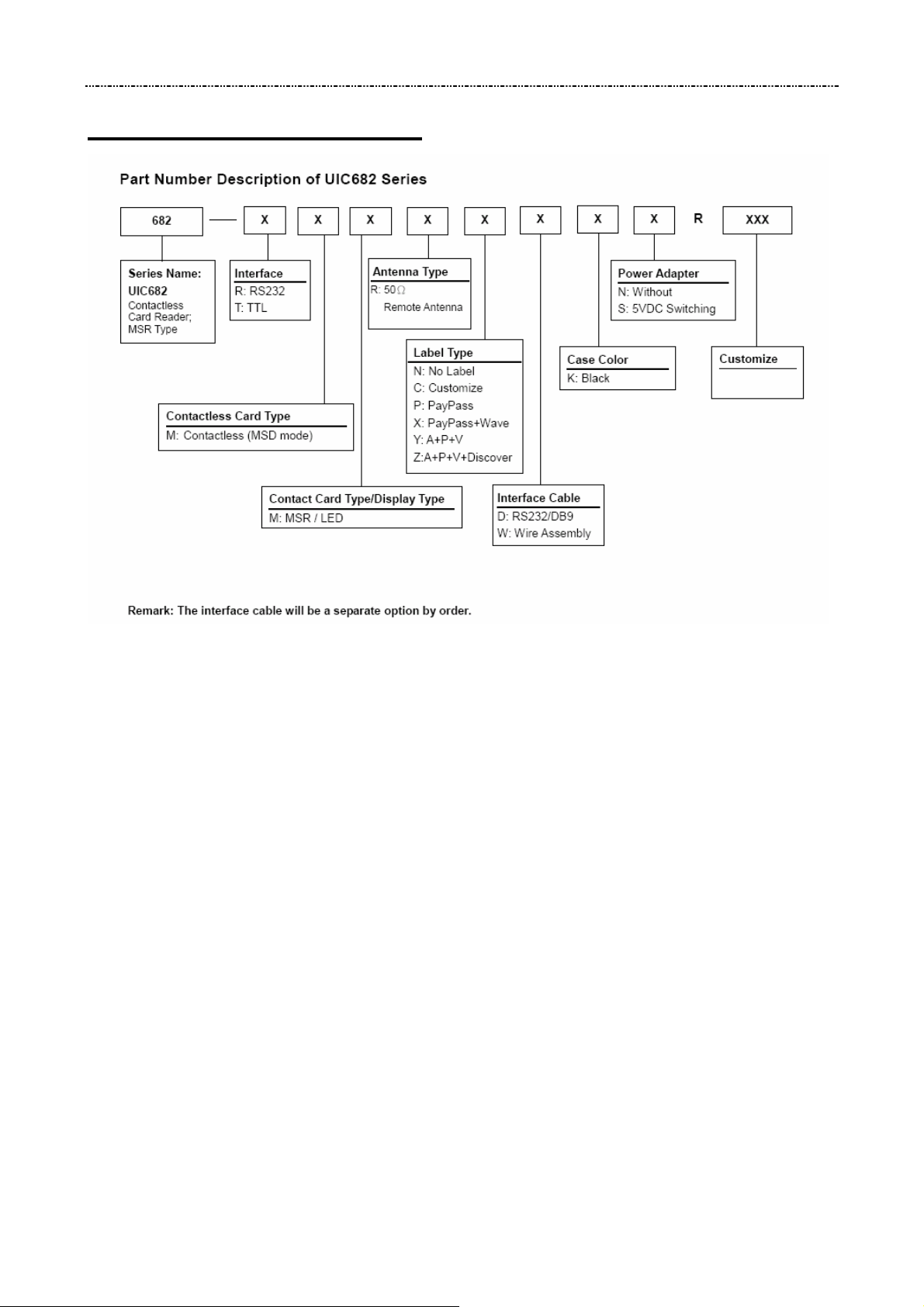
1.3 Part Number Description
1-2
UIC682 Programmer’s Manual UDN PM070-U Rev. 1
Section2: Configurations
This section shows the dimensions and accessories of the UIC682.
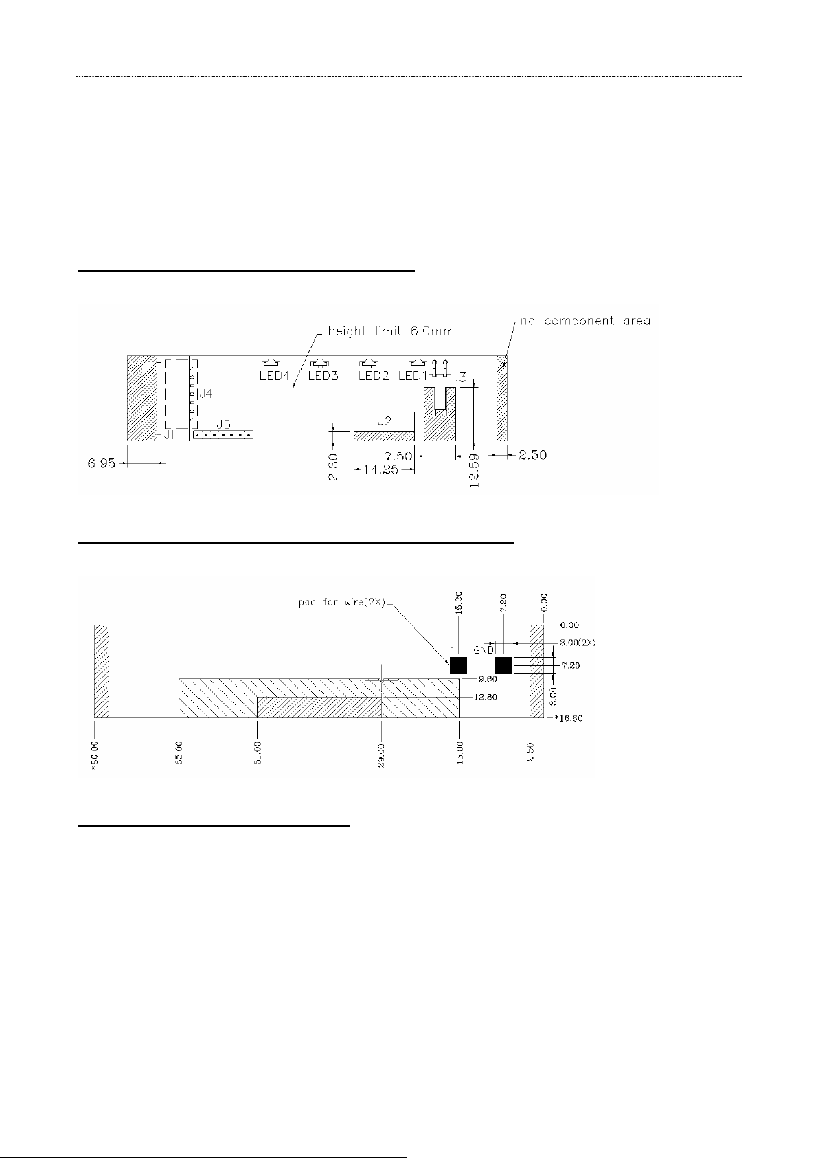
2.1 Dimensions of UIC682 PCBA
Figure 2-1 Dimensions of UIC682
2.2 Dimensions of Remote Antenna PCBA
Figure 2-2 Dimensions of Remote Antenna PCBA
2.3 Accessories of UIC682
The following accessories should be supplied along with UIC682. Make sure all the
following accessories are contained in your package.
1. Interface cable - DB9 male connector 1.5M
2. Power adapter 5VDC 500mA (RS232 interface only)
2-1

UIC682 Programmer’s Manual UDN PM070-U Rev. 1
Section3: Technical Specifications
3.1 Functional Specifications
• Contactless communication at 13.56MHz
• Proximity operation distance of up to 100mm
• LED indication (support PayPass application)
• Audio buzzer
• Support RS232 data output baud rate up to 115.2K BPS
• Support RS232 pass through baud rate up to 38400 BPS
• Support TTL level for serial data output (optional)
• Support TTL level for F2F decoder data output emulation (optional)
• Support Remote 50 ohm matching antenna
• Support all layers of 14443 including the type A and B communication scheme
• Support contactless communication using MIFARE higher baud rate up to 424KHz
• Support the MIFARE Classic products
• Support American Express ExpressPay transaction application
• Support MasterCard PayPass transaction application
• Support Visa MSD transaction application
3.2 Mechanical Specifications
• Dimension Without antenna board Length: 87 mm Width: 20 mm
3-1

UIC682 Programmer’s Manual UDN PM070-U Rev. 1
3.3 Electrical Specifications
• Power Required 5VDC
• Power Consumption 350mA in operating mode
• Communication Standard RS232 signal level TTL 5V signal level (optional)
• Communication Signal (RS232) Logic 1 = -3 volts to –15 volts or TTL level 5 volts Logic 0 = +3 volts to +15 volts or TTL level 0 volt
3.4 Environmental Specifications
• Temperature Operating: -10 ~ 50℃
Storage: -30 ~ 70℃
• Humidity Operating: 10 ~ 85% (non condensing) Storage: 10 ~ 90% (non condensing)
3-2
 Loading...