


3,13DG
3URJUDPPHU¶V0DQXDO
3HUVRQDO,'1XPEHU3DG
:LWK(09/HYHO7UDQVDFWLRQ&DSDELOLWLHV
3&,326$6SHFLILFDWLRQ
308
5HYLVLRQ

PIN Pad 791 Programmer’s Manual (PCI POS-A) UDN PM0103-U Rev. 06
Notice, Agency Approved, and Warranty 2015-04-20
NOTICE
The issuer of this manual has made every effort to provide accurate information. The issuer will not be held
liable for any technical and editorial omission or errors made herein; nor for incidental consequential
damages resulting from the furnishing, performance or use of this material. This document contains
proprietary information that is protected by copyright. All rights are reserved. No part of this document may be
photocopied, reproduced, or translated without the prior written consent of the issuer. The information
provided in this manual is subject to change without notice.
第十二條 經型式認證合格之低功率射頻電機,非經許可,公司、商號或使用者均不得擅自變更頻率、 大功率
或變更原設計之特性及功能。
第十四條 低功率射頻電機之使用不得影響飛航安全及干擾合法通信;經發現有干擾現象時,應立即停用,並改
善至無干擾時方得繼續使用。
前項合法通信,指依電信法規定作業之無線電通信。低功率射頻電機須忍受合法通信或工業、科學及醫療用電
波輻射性電機設備之干擾。
AGENCY APPROVED
- FCC class B
- CE class B
WARRANTY
This product is served under one-year warranty to the original purchaser. Within the warranty period,
merchandise found to be defective would be repaired or replaced. This warranty applies to the products only
under the normal use of the original purchaser, and in no circumstances covers incidental or consequential
damages through consumers’ misuse or modification of the products.
Page 2
Uniform Industrial Corp. Proprietary and Confidential Total 342 pages

PIN Pad 791 Programmer’s Manual (PCI POS-A) UDN PM0103-U Rev. 06
Notice, Agency Approved, and Warranty 2015-04-20
Document History
Document Version Apply to FW version Change
01 PP791: 10A.01
SysMgr: 10A.01
02 PP791: 10A.03
SysMgr: 10A.03
03 PP791: 10A.05
SysMgr: 10A.04
04 PP791: 10A.06
SysMgr: 10A.05
05 PP791: 10A.06
SysMgr: 10A.05
First Release
Modify the description of I17 command.
Remove “All” type of saver screen setting in BB
command.
Add a error code in 71 command.
Add a error code in 91 command.
Add a error code in 02 command.
Add a error code in 91 command.
Add message JA for set boot logo.
EMV Level 2 transaction messages for PCD
implementation done.
Add Contactless EMV transaction description in EMV
Level 2 transaction messages.
Message T19, T23 update message flow.
Add PCD MiFare Message.
Split EMV transaction chapter into two, Contact and
06 PP791: 10A.09
SysMgr: 10A.08
Contactless EMV transaction.
Remove I10 command.
Add a new description of WIFI/BT setting menu.
Add NCC Compliance and Advisory Statement.
Page 3
Uniform Industrial Corp. Proprietary and Confidential Total 342 pages

PIN Pad 791 Programmer’s Manual (PCI POS-A) UDN PM0103-U Rev. 06
Section 1 – Introduction 2015-04-20
Table of Contents
Section 1 Introduction _________________________________________________ 11
PIN Pad components _______________________________________________________________ 11
Display ________________________________________________________________ 12
Keypad ________________________________________________________________ 12
Communication Interface __________________________________________________ 12
Magnetic and Smart Card reader ____________________________________________ 12
Smart card and Security Access Module (SAM) interfaces ________________________ 13
Tamper Evidence and Tamper Responsive ____________________________________________ 13
Section 2 System Manager _____________________________________________ 14
Introduction 14
Security management ______________________________________________________________ 14
Main menu of system manager ______________________________________________________ 15
Prepare downloading ______________________________________________________________ 15
“Download” menu _________________________________________________________________ 16
“Date & Time” menu _______________________________________________________________ 17
“Setting” menu 17
“System Info” menu _______________________________________________________________ 18
“Self Test” menu __________________________________________________________________ 18
“Change Password” menu __________________________________________________________ 19
Section 3 PP791 Setup & Diagnostic Menu ________________________________ 20
Call up Diagnostic Menu ____________________________________________________________ 20
Diagnostic Menu 1: HW Tests _______________________________________________________ 20
Diagnostic Menu 2: Display Info _____________________________________________________ 21
Diagnostic Menu 3: Setup COM Port __________________________________________________ 21
Diagnostic Menu 4: Set LCD Backlight ________________________________________________ 22
Diagnostic Menu 5: Logo Setup ______________________________________________________ 23
Diagnostic Menu 6: Setup Password _________________________________________________ 23
Diagnostic Menu 7: Set Keypad Beep _________________________________________________ 23
About USB virtual COM port (only applied on USB version) ______________________________ 24
Call up Interface Setting Menu _______________________________________________________ 24
Interface Setting Menu 1: COMM. Interface Switch ______________________________________ 24
Interface Setting Menu 2: WIFI Setting ________________________________________________ 24
Interface Setting 3: Bluetooth Setting _________________________________________________ 25
Interface Setting Menu 4: Status _____________________________________________________ 25
Section 4 Message format ______________________________________________ 26
Notation Conventions ______________________________________________________________ 26
Control Codes ___________________________________________________________ 26
Message frame summary ___________________________________________________________ 27
Page4
Uniform Industrial Corp. Proprietary and Confidential Total 342 pages

PIN Pad 791 Programmer’s Manual (PCI POS-A) UDN PM0103-U Rev. 06
Section 1 – Introduction 2015-04-20
Message type ___________________________________________________________ 27
Time-out _______________________________________________________________ 27
Transmission Error _______________________________________________________ 27
Packet Error ____________________________________________________________ 27
Section 5 Administration and maintenance messages _______________________ 28
Message 02 Load Master Key ____________________________________________________ 28
Symmetric Keys Loading Authentication ______________________________________________ 32
Message 04 Check Master Key ____________________________________________________ 34
Message 05 Load Serial Number __________________________________________________ 36
Message 06 Get Serial Number ___________________________________________________ 37
Message 07 Test DES Implementation ______________________________________________ 38
Message 08 Select Master Key ____________________________________________________ 39
Message 09 Communication Test _________________________________________________ 40
Message 11 PIN Pad Device Connection Test _______________________________________ 42
Message 12 Select Prompt Language ______________________________________________ 43
Message 13 Adjust COM1 Baud Rate (RS-232 version only) ___________________________ 45
Message 14 Enable/Disable Timer Display __________________________________________ 47
Message 15 Adjust LCD Backlight Level ____________________________________________ 49
Message 16 Remote self-test request ______________________________________________ 50
Message 17 Request random number ______________________________________________ 51
Message 18 Set PIN pad system time ______________________________________________ 52
Message 19 Query Firmware Version ______________________________________________ 56
Message 1C Query Hardware Capability ___________________________________________ 58
Message 1F Query Usable Prompt Table ____________________________________________ 59
Message 1J Turn ON/OFF LCD Backlight ___________________________________________ 61
Message 1K Turn ON/OFF LCD Power-save mode ____________________________________ 63
Message 1M Setup Keypad Beeper _________________________________________________ 65
Section 6 Contact EMV Level 2 transaction messages ________________________ 67
Message T01 Terminal Configuration Setup _________________________________________ 69
Message T02 Terminal Configuration Setup Response ________________________________ 72
Message T03 Certification Authority Public Key Setup ________________________________ 73
Message T04 Certification Authority Public Key Setup Response _______________________ 75
Message T05 EMV Application Configuration Setup __________________________________ 76
Message T06 EMV Application Configuration Setup Response _________________________ 80
Message T07 Data Format Table Setup _____________________________________________ 81
Message T08 Data Format Table Setup Response ____________________________________ 83
Message T09 EMV Config Data Query Message ______________________________________ 84
Message T0A Response of EMV Config Data Query Message _____________________________ 85
Message T0B Delete EMV Configuration Data Message. _________________________________ 86
Message T0C Response of Delete EMV Configuration Data Message. ______________________ 87
Page5
Uniform Industrial Corp. Proprietary and Confidential Total 342 pages

PIN Pad 791 Programmer’s Manual (PCI POS-A) UDN PM0103-U Rev. 06
Section 1 – Introduction 2015-04-20
Message T11 Application Select ___________________________________________________ 88
Message T12 Application Select Response _________________________________________ 89
Message T13 Application Select Next ______________________________________________ 90
Message T15 Start Transaction ____________________________________________________ 91
Message T16 Start Transaction Response __________________________________________ 93
Message T17 Send Online Authorized Code _________________________________________ 95
Message T19 Send Issuer Script Command _________________________________________ 97
Message T1D Transaction Data loading _______________________________________________ 99
Message T1E Transaction Data loading Response ____________________________________ 101
Message T20 Send Issuer Script Command Response _______________________________ 102
Message T21 Get Transaction Result’s Data ________________________________________ 103
Message T22 Get Transaction Result’s Data Response _______________________________ 104
Message T23 Erase EMV Transaction Log. _________________________________________ 105
Message T1C Terminal Cancel Transaction ___________________________________________ 106
Message T25 Get Batch Data ____________________________________________________ 107
Message T26 Response of Get Batch Data message _________________________________ 109
Message T27 Get Online authorization Data ________________________________________ 110
Message T28 Response of Get Online authorization Data message ____________________ 111
Message T29 Get Reversal Data __________________________________________________ 112
Message T2A Response of Get Reversal Data message _________________________________ 113
Overall Contact EMV Level 2 transaction flow reference ________________________________ 114
Ref. 1 Packet command flow for transaction with offline ____________________ 114
Ref. 2 Packet command flow for transaction with online _____________________ 114
Ref. 3 Packet command flow for transaction with MSR. _____________________ 115
Ref. 4 Packet command flow for transaction with online and Issuer Script command
Processing 116
Ref. 5 Packet command flow for first EMV application is blocked _____________ 116
Section 7 Contactless EMV Level 2 transaction messages __________________ 118
Message T51 PCD Terminal Configuration Setup _____________________________________ 120
Message T52 PCD Terminal Configuration Setup Response _____________________________ 123
Message T53 PCD Certification Authority Public Key Setup _____________________________ 124
Message T54 PCD Certification Authority Public Key Setup Response ____________________ 126
Message T55 PCD Application Configuration Setup ____________________________________ 127
Message T56 PCD Application Configuration Setup Response ___________________________ 131
Message T59 PCD Config Data Query Message________________________________________ 132
Message T5A Response of PCD Config Data Query Message ____________________________ 133
Message T5B Delete PCD Configuration Data Message. ________________________________ 134
Message T5C Response of Delete PCD Configuration Data Message. _____________________ 135
Message T5D PCD House Keeping Message. _________________________________________ 136
Message T5E Response of PCD House Keeping Message. ______________________________ 137
Page6
Uniform Industrial Corp. Proprietary and Confidential Total 342 pages

PIN Pad 791 Programmer’s Manual (PCI POS-A) UDN PM0103-U Rev. 06
Section 1 – Introduction 2015-04-20
Message T61 Start Transaction _____________________________________________________ 138
Message T62 Start Transaction Response ____________________________________________ 140
Message T63 Get Transaction Result’s Data __________________________________________ 141
Message T64 Get Transaction Result’s Data Response _________________________________ 142
Message T65 Get Online authorization Data __________________________________________ 143
Message T66 Response of Get Online authorization Data message _______________________ 144
Message T6C Cancel PCD Transaction _______________________________________________ 145
Message T71 Send PCD Online Authorized Code ______________________________________ 146
Message T73 Send Issuer Script Command ________________________________________ 148
Message T75 Revocation List Setup _________________________________________________ 149
Message T76 Revocation List Setup Response ________________________________________ 150
Message T77 Exception List Setup __________________________________________________ 151
Message T78 Exception List Setup Response _________________________________________ 152
Overall Contactless EMV Level 2 transaction flow reference _____________________________ 153
Ref. 1 Packet command flow for transaction with offline approval _____________ 153
Ref. 2 Packet command flow for transaction with online approval _____________ 154
Section 8 MIFARE card messages ______________________________________ 155
Message P01 Enable/Disable MIFARE _____________________________________________ 156
Message P02 Query MIFARE Presence ____________________________________________ 158
Message P03 MIFARE Anti-collision _______________________________________________ 160
Message P04 MIFARE Selection __________________________________________________ 162
Message P05 MIFARE Classic/Ultralight Card Activation _____________________________ 164
Message P06 MIFARE Classic/Ultralight Card HALT _________________________________ 166
Message P07 MIFARE Classic Card Authentication ___________________________________ 168
Message P08 MIFARE Ultralight Card Read Page ____________________________________ 170
Message P09 MIFARE Ultralight Card Write Page _____________________________________ 172
Message P10 MIFARE Classic/Ultralight Card Read Block ____________________________ 174
Message P11 MIFARE Classic/Ultralight Card Write Block _____________________________ 176
Message P12 MIFARE Classic/Ultralight Card Read Sector ____________________________ 178
Message P13 MIFARE Classic/Ultralight Card Write Sector ___________________________ 180
Message P14 MIFARE Classic Card Value Operation __________________________________ 182
Message P15 Load MIFARE key __________________________________________________ 184
Message P16 Identify MIFARE Card Type ___________________________________________ 186
Message P17 MIFARE DESfire Card Activation ______________________________________ 188
Message P18 MIFARE DESfire Card Deselect ________________________________________ 190
Message P19 I/O to MIFARE card with APDU format _________________________________ 192
Message P20 I/O to MIFARE card for block data exchange _____________________________ 194
Overall MIFARE operation flow reference _____________________________________________ 196
Ref. 1 Activate and authenticate for MIFARE classic card. ___________________ 196
Ref. 2 The quick method for activating classic card. ________________________ 197
Page7
Uniform Industrial Corp. Proprietary and Confidential Total 342 pages

PIN Pad 791 Programmer’s Manual (PCI POS-A) UDN PM0103-U Rev. 06
Section 1 – Introduction 2015-04-20
Ref. 3 Activate and authenticate for MIFARE Ultralight card. ________________ 198
Ref. 4 The quick method for activating Ultralight card. ______________________ 199
Ref. 5 Activating for DESFire card _____________________________________ 200
Section 9 Online transaction messages with Master/Session Keys (MK/SK) ____ 201
Message 70 PIN entry request (MK/SK) ____________________________________________ 201
Message 71 Encrypted PIN Block Response _______________________________________ 204
Message 72 PIN Entry Cancel ____________________________________________________ 206
Message Z0 Move Display Cursor ________________________________________________ 207
Message Z1 Reset State ________________________________________________________ 208
Message Z2 Display String ______________________________________________________ 209
Message Z3 Display Line Prompts ________________________________________________ 212
Z2 / Z3 Authenticated mode with fixed prompt ________________________________________ 215
Z2 / Z3 PIN entry mode with fixed prompt_____________________________________________ 215
Message Z2 Display String with Authentication Code ________________________________ 216
Message Z3 Display Line Prompts with Authentication Code _________________________ 218
Example to use Z2 / Z3 with Authencation Code. ______________________________________ 220
Message Z42 Read Key Code ____________________________________________________ 221
Message Z43 Read Key Code Response ___________________________________________ 222
Message Z50 String Entry Request _______________________________________________ 223
Message Z51 String Entry Response ______________________________________________ 225
Message Z60 PIN entry request with external prompt (MK/SK) ________________________ 226
Message Z62 PIN entry request with customized prompt (MK/SK) _____________________ 228
Message Z66 Message Authentication Code (MAC) Request __________________________ 231
Message Z67 Message Authentication Code (MAC) Response_________________________ 234
Message Z7 Turn ON/OFF CANCEL Message Display ________________________________ 236
Message Z8 Set Idle Prompt _____________________________________________________ 237
Section 10 Online transaction messages with Derived Unique Key per Transaction
(DUKPT) _____________________________________________________________ 238
Message 60 Pre-authorization PIN Entry Request ___________________________________ 239
Message 62 Pre-authorization Amount Authorization Request ________________________ 241
Message 63 Pre-authorization Amount Authorization Response _______________________ 242
Message 70 PIN Entry Request (DUKPT) __________________________________________ 243
Message 71 Encrypted PIN Block Response _______________________________________ 245
Message 72 PIN Entry Cancel ____________________________________________________ 246
Message Z60 PIN entry request with external prompt (DUKPT) ________________________ 247
Message Z62 PIN entry request with customized prompt (DUKPT) _____________________ 249
Message 76 PIN Entry Test Request ______________________________________________ 252
Message 7A KSN output format _____________________________________________________ 253
Message 90 Load First Initial Key Request _________________________________________ 254
Message 91 Load Initial Key Response ____________________________________________ 256
Page8
Uniform Industrial Corp. Proprietary and Confidential Total 342 pages

PIN Pad 791 Programmer’s Manual (PCI POS-A) UDN PM0103-U Rev. 06
Section 1 – Introduction 2015-04-20
Message 94 Load Second Initial Key Request ______________________________________ 257
Message 96 Select Active Key Set ________________________________________________ 259
Section 11 ICC / SAM / Magnetic stripe card manipulating messages _________ 260
Message I00 Query Primary Smart Card Presence ___________________________________ 261
Message I01 Primary Smart Card Cold Reset _______________________________________ 262
Message I02 Primary Smart Card ATR Response ____________________________________ 263
Message I04 Primary Smart Card Deactivate ________________________________________ 264
Message I06 Primary Smart Card C-APDU __________________________________________ 265
Message I07 Primary Smart Card R-APDU __________________________________________ 266
Message I08 Smart Card Offline PIN Verification (EMV) _______________________________ 267
Message I09 Response of Smart Card Offline PIN Verification (EMV) ___________________ 269
Message I0F Error Codes _______________________________________________________ 270
Message I11 SAM slot Cold Reset_________________________________________________ 271
Message I12 SAM slot ATR Response _____________________________________________ 272
Message I14 SAM slot Card Deactivate ____________________________________________ 273
Message I15 SAM Select Interface ________________________________________________ 274
Message I16 SAM slot C-APDU ___________________________________________________ 275
Message I17 SAM slot R-APDU ___________________________________________________ 276
Message Q1 Display SWIPE CARD message_______________________________________ 277
Message Q2 Transaction Completed ______________________________________________ 278
Message Q3 Ignore Card Swipe __________________________________________________ 279
Message Q4 Enable/Disable Magnetic Card Reader _________________________________ 280
Message Q5 Set MSR Retry Count ________________________________________________ 281
Message Q6 MSR Operation Control _____________________________________________ 282
Message Q7 MSR Mode Query ___________________________________________________ 283
Message Q8 Display TAP CARD message __________________________________________ 284
Message Q9 Display SWIPE / TAP CARD message __________________________________ 285
Message QA Enable/Disable Contactless Card Reader ______________________________ 286
Message QB MSR Device (Not) Always Detection ___________________________________ 287
Message QC Contactless module (Not) Always Detection ____________________________ 288
Message QD Contactless Card Data with/without Start/End sentinels __________________ 289
Message 81 MSR Card Data _____________________________________________________ 290
Message 83 Contact-less Card Data ______________________________________________ 292
Section 12 Display functionality messages _______________________________ 293
Message B1 Font Size Selection __________________________________________________ 294
Message B3 Font Color (Foreground / Backgroud) Selection __________________________ 295
Message BB Screen Saver Setting ________________________________________________ 296
Message BD Enable / Disable Screen Saver ________________________________________ 298
Message BF Screen Saver Preview / Stop Preview___________________________________ 299
Section 13 JPEG File Operation messages _______________________________ 300
Page9
Uniform Industrial Corp. Proprietary and Confidential Total 342 pages

PIN Pad 791 Programmer’s Manual (PCI POS-A) UDN PM0103-U Rev. 06
Section 1 – Introduction 2015-04-20
Message J0 JPEG File Table Initialization __________________________________________ 301
Message J1 Query JPEG File Table _______________________________________________ 302
Message J2 Select JPEG File ____________________________________________________ 304
Message J3 Delete JPEG File ____________________________________________________ 306
Message J4 Download JPEG File _________________________________________________ 308
Message J5 Upload JPEG File ___________________________________________________ 310
Message J6 Play JPEG File______________________________________________________ 312
Message J7 Set JPEG File As Idle Prompt _________________________________________ 313
Message J8 Enable/Disable Idle Logo Functionality _________________________________ 314
Message J9 Show JPEG File ____________________________________________________ 315
Message JA Set Boot Logo ________________________________________________________ 317
Appendix A Key management __________________________________________ 319
Appendix B PIN Block Format__________________________________________ 327
ANSI x9.8 format (MK/SK, DUKPT, and Offline clear text PIN entry) _______________________ 327
EMV Level 2 format (Offline enciphered PIN entry) _____________________________________ 328
Appendix C Features and specification __________________________________ 329
Appendix D Tag Definition on EMV data _________________________________ 330
Appendix E Minimum Set of EMV Configuration Data ______________________ 333
Appendix F PCD Tag Definition on EMV data _____________________________ 334
Appendix G PCD Minimum Set of EMV Configuration Data __________________ 337
Appendix H Fixed Prompts for Z2/Z3 authenticated mode ___________________ 339
Appendix I Fixed Prompts for Z2/Z3 PIN entry mode _______________________ 341
Page10
Uniform Industrial Corp. Proprietary and Confidential Total 342 pages

PIN Pad 791 Programmer’s Manual (PCI POS-A) UDN PM0103-U Rev. 06
Section 1 – Introduction 2015-04-20
Section 1 Introduction
PIN Pad 791 (PP791) provides a secure and friendly way of obtaining customer Personal Identification
Numbers (PIN), dealing with smart card offline transaction specified in EMV Level 2 book 3 and book4.
PP791 can deal PIN entry and transaction in following ways:
1. As a PIN Entry Device (PED): PP791 can encrypt ANSI X9.8 standard PIN block by DES and TDES
algorithm, using master/session key or DUKPT as key management scheme. In addition, it can
encrypt EMV Level 2 specified PIN block by DES or RSA algorithm.
2. As an EMV Lv2 mini terminal: PP791 can handle most of the EMV Level 2 transaction flow,
especially card holder verification (CHV) process, and send transaction result to its host machine.
With properly development tool, system integrators can develop their customized application for
PP791, use its internal function calls to build their own transaction flow. PP791 will secure the
sensitive data by restricting the memory space that can be accessed by customized application
program.
PIN Pad components
This PIN Pad is composed of the following components:
(5)
(6)
(1)
(2)
(7)
(3)
(4)
(1). LCD display with 320 * 240 resolution.
(2). Magnetic stripe reader swiping slot.
(3). 13 key telephone-style keypad and 3 function keys.
(4). Smart card reader inserting slot.
(5). Primary communication interface (RS232 or USB), with protection cover
(6). Ethernet LAN Port
Page11
Uniform Industrial Corp. Proprietary and Confidential Total 342 pages

PIN Pad 791 Programmer’s Manual (PCI POS-A) UDN PM0103-U Rev. 06
Section 1 – Introduction 2015-04-20
(7). Three secure access module (SAM) slots, with protection cover.
Display
The 320*240 pixels TFT LCD is capable of displaying characters and graphic. For displaying characters,
It provides ASCII 8*8 character set for range 0x20~0x7E, 8*16, 16*16, 16*24 character set for range
0x20~0xFF.
Keypad
The PIN Pad uses its 16 keys to accept commands. For each key pressed, there will be a short beep to
confirm that key is accepted. The following diagram shows layout of the keys.
1 2 3
4 5 6
7 8 9
0
CAN
CLR
[CAN] (Cancel) button will abort PIN entering transactions or magnetic card swiping actions, and cause
PP791 back to idle state.
[CLR] (Clear) button will reset PIN input when doing PIN entry transactions.
[F1] The F1 button is treated as “move up” when dealing with function menu (such as diagnostic
mode or EMV Lv2 transaction menu). With customized application, system integrators can define
its usage by themselves.
[F2] The F2 button is treated as “go back” when dealing with function menu. With customized
application, system integrators can define its usage by themselves.
ENTER
F1 F2 F3
[F3] The F3 button is treated as “move down” when dealing with function menu. With customized
application, system integrators can define its usage by themselves.
Communication Interface
PP791 has two communication interfaces:
1. A detachable 9-pin Mini-DIN interface which can be used to connect proprietary RS232/USB auto
selecting cable for power feeding and data exchange with host device.
2. A RJ-45 Ethernet jack for TCP/IP communication.
Magnetic and Smart Card reader
The smart card reader of PP791 can accept EMV Level 2 compatible smart cards for offline transaction,
Page12
Uniform Industrial Corp. Proprietary and Confidential Total 342 pages

PIN Pad 791 Programmer’s Manual (PCI POS-A) UDN PM0103-U Rev. 06
Section 1 – Introduction 2015-04-20
or exchange APDU packets with EMV Level 1 compatible smart cards via ICC-related commands. It also
reads ISO 7811 compatible magnetic cards for legacy online debit / credit card operation.
Smart card and Security Access Module (SAM) interfaces
PP791 provides three SAM interfaces (optional) for customer usage. System Integrators can use PP791
internal API or SAM-related commands to switch between different slots and exchange APDU.
Tamper Evidence and Tamper Responsive
PP791 is compatible with “Payment Card Industry (PCI) POS PIN entry device security requirement”
version 3.0. Per this requirement, PP791 will detect tampering attempts by its multiple security design. If
tamper is detected, security subsystem will cause the automatic and immediate erasure of all secret
information contained in it. Such as master keys, DUKPT key, personalization information and so on.
Without security information PP791 will not work anymore. A user should contact system
integrator or vendor representative for RMA when a PP791 was tampered.
Page13
Uniform Industrial Corp. Proprietary and Confidential Total 342 pages

PIN Pad 791 Programmer’s Manual (PCI POS-A) UDN PM0103-U Rev. 06
Section 2 –System Manager 2015-04-20
Section 2 System Manager
Introduction
The system manager is a resident process launched automatically when PP791 boot up. It will manage
the download and execution of other application, do basic settings, and self tests.
After system booted up and the startup application is launched, user can press “ENT + 1” (press ENT
key and ‘1’ at the same time), then input dual passwords of system manager to enter system manager
menu. (The default password will be sent to legal user by secure method).
NOTE 1: Enter system manager will terminate the current application.
NOTE 2: System manager will exit and re-launch startup application if no input over 60 seconds.
Security management
1. Personalization and tamper detection
Each PP791 is “personalized” (create an AES key randomly for sensitive data protection) before
delivery. Every time PP791 boot up, system manager will check the personalization status and
existence of this AES key. If device is tampered, security mechanism will erase the AES key and
invalid personalization status, then reboot. After reboot, system manager will see the change and
show following message (tamper evidence mode):
“System has tampered, you shall release it before you can normally use.”
In this situation, user can press “ENT + 1” (press ENT key and ‘1’ at the same time), then input
dual passwords of system manager to exit tamper evidence mode.
When exiting tamper evidence mode, PP791 will be re-personalized. All keys will be erased.
2. Certificate management
Every application in the PP791 should have digital signature (sha256 hash encrypted by 2048bit
RSA key) The system process (system manager and PP791 appl.,) will be verified by a fixed
system certificate resident in system kernel, and user applications will be verified by user-loaded
certificates, which is managed by system manager.
The certificate hierarchy of PP791 contains:
Vendor certificate: This certificate is created by user (i.e. system integrator or bank), it verifies user
applications when downloading application and launching application.
Intermediate certificate: This certificate is issued by intermediate CA, it verifies vendor certificate
every time when system manager starts.
Root certificate: This certificate is issued by root CA, by default, PP791 have a root certificate
resident in system kernel. But users can load their own root certificate along with intermediate and
vendor certificate in the same trust chain. It verifies intermediate certificate every time when
system manager starts.
Page14
Uniform Industrial Corp. Proprietary and Confidential Total 342 pages
PIN Pad 791 Programmer’s Manual (PCI POS-A) UDN PM0103-U Rev. 06
Section 2 –System Manager 2015-04-20
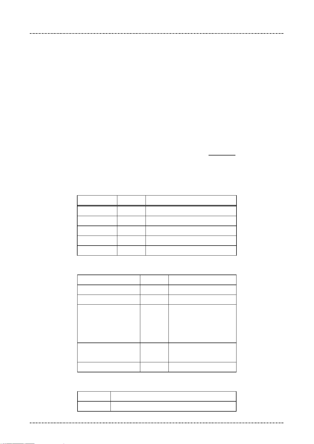
Main menu of system manager
DISPLAY ACTION
Key Injection
Download
Date & Time
Setting
System Info
Self Test
Change Password
Do clear text key load.
Do firmware updates.
Adjust system date, time, and time zone.
Set up system manager options.
Show firmware version, TCP/IP settings, and certificate names.
Do basical hardware test.
Change system manager password.
Prepare downloading
User has to use system manager to download applications, graphics, or update system components.
There are two methods to download: via TCP/IP (need to a FTP server, and correctly setup IP address
and FTP config scripts by “Setting” menu).
Prepare FTP server:
User can establish a FTP server on any computer that already connected to LAN and have valid IP
address. The server should have a directory (i.e. ftproot/pub) that contains following directory (case
sensitive):
1. certs: Contains certificate files with pre-defined names: “appl_vendor.crt” for vendor
certificate; “appl_inter.crt” for intermediate certificate; “custom_root.crt” for customized
root certificate if needed; “certificates.tar.gz” for package download if needed.
2. graphics: Contains a “graphics.lst” file and picture packages in tar.gz format.
3. system: Contains system update files provided by UIC.
The list files (graphics.lst) are pure text file, with one name per line:
Graph_01
Graph_02
.....
When PP791 reads “Graph_01”, in graphics.lst, it will go to server to find “Graph_01.tar.gz”.
Prepare FTP config script:
PP791 can manage multiple FTP settings by selecting config script. Each config script should have the
extension name “.cfg”, with following format:
host=xxx.xxx.xxx.xxx
port=21
user=anonymous
Page15
Uniform Industrial Corp. Proprietary and Confidential Total 342 pages
IP address of FTP server.
FTP port number.
FTP login name.
PIN Pad 791 Programmer’s Manual (PCI POS-A) UDN PM0103-U Rev. 06
Section 2 –System Manager 2015-04-20
password=xxxxxx
FTP login password.
path=/pub
PP791 will read an “ftp_setting_file” which contains one ftp config script name, and use it as
default FTP setting. The factory default of ftp_setting_file is:
ftp_site1.cfg
(As a result, system manager will read server IP address, port, username and password from this file).
The FTP setting file and config scripts can by edited by system manager.
Directory name that contains appls, certs, graphics and system.
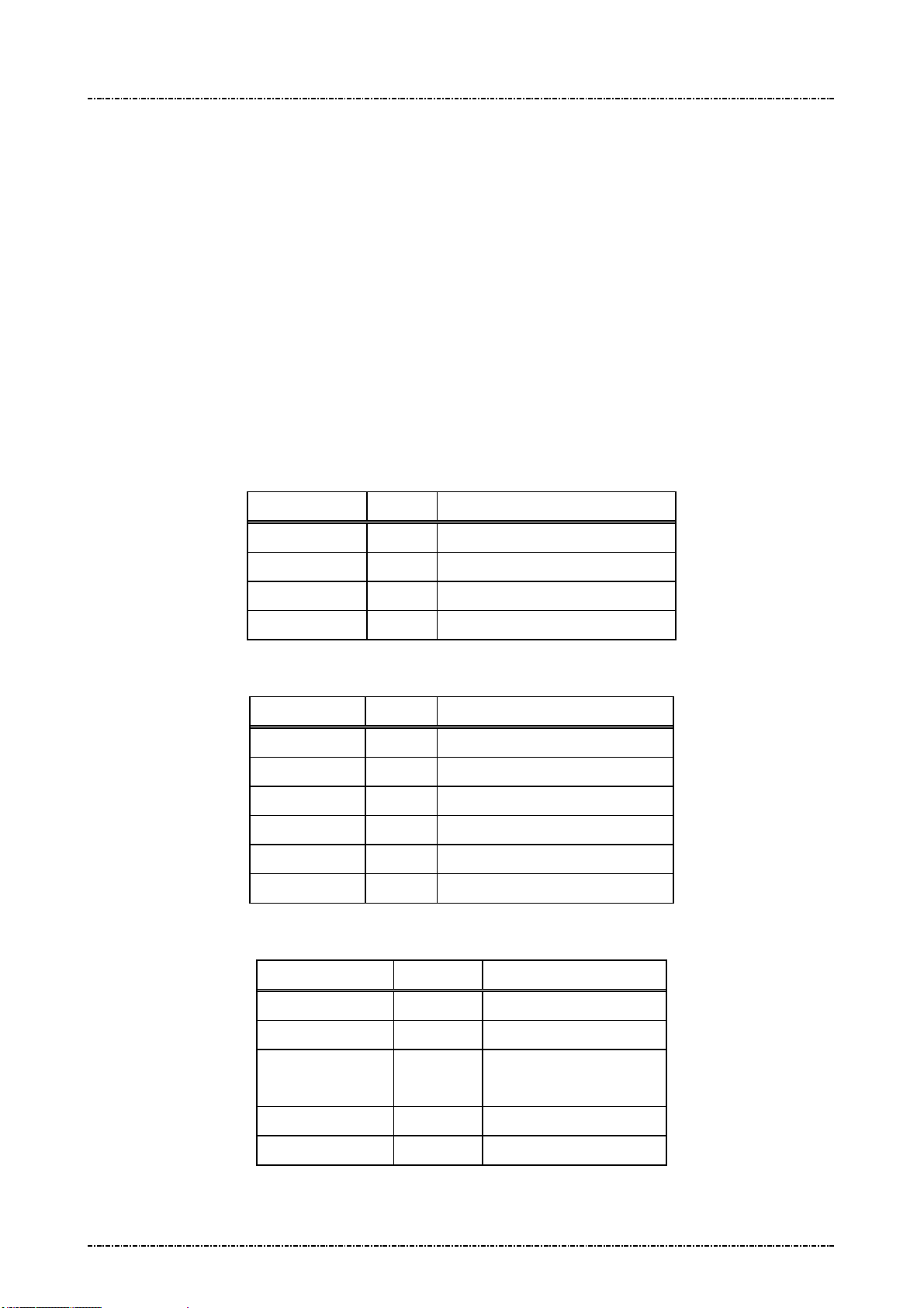
“Download” menu
DISPLAY ACTION
Download System
Download Graphics
Download Certs
Select download method; Then show system update menu.
Select download method; Then show graphics download menu.
Select download method; Then show certificates download
menu
“Download System” menu:
DISPLAY ACTION
PIN Pad 791
System Manager
Linux Kernel
Root Filesystem
Note: these update files will be signed by UIC and verified by built-in UIC system certificate.
“Download Graphics” menu:
The graphic package (.tar.gz format) should have a subdirectory:
jpeg: JPEG pictures (Refer to Jxx commands of PP791)
DISPLAY ACTION
Download Graphics
Update PP791 application.
Update System Manager.
Update Linux kernel of PP791.
Update system files of PP791.
Display graphic package names from “graphics.lst” resident in
PP791. Use [F1] ~ [F3] to navigate, [ENT] to start download
graphic package.
If download success, system manager will copy graphics in the
package file to system graphics directory.
Download Graphics List
“Download Certs” menu:
Page16
Uniform Industrial Corp. Proprietary and Confidential Total 342 pages
Download “graphics.lst” from server.

PIN Pad 791 Programmer’s Manual (PCI POS-A) UDN PM0103-U Rev. 06
Download Intermediate
Section 2 –System Manager 2015-04-20
DISPLAY ACTION
Download Vendor Cert.
Cert.
View current cert. CN
Lock/Unlock Cert. CN
“Date & Time” menu
DISPLAY ACTION
Current date/time
Download “appl_vendor.crt”
Download “appl_inter.crt”
View CN (common name) of current intermediate and vendor
certificate.
This option , if enabled, will cause system manager to check the
CN (common name) field of newly downloaded certificate; if
new CN is different than old one, system manager will reject
this certificate.
Display current time zone,
Current RTC time (UTC).
Set time zone
Set date/time
“Setting” menu
DISPLAY ACTION
Set DHCP / IP
Current Local time.
1. Enter the name of local time zone. (3~6 bytes)
2. Input the time offsets from UTC. (use [F1] to add minus sign)
3. Enter the name of Daylight Saving Time (DST) or press
[CAN] to skip the related settings of DST.
4. Input the time offsets of DST from UTC.
5. Enter the start date and time of DST.
6. Enter the date and time to set the end of DST.
1. Enter year, month, day, hour (24h format), minute, second.
2. Press [ENT] to set time, or [CAN] to cancel.
Bring up sub menu of basic TCP/IP settings
Page17
Uniform Industrial Corp. Proprietary and Confidential Total 342 pages
[Set DHCP]
Enable or disable DHCP client of PP791. This setting will effect
after reboot.
[Set Local IP]
Set fixed IP address of PP791 if DHCP disabled.
[Set Gateway IP]
PIN Pad 791 Programmer’s Manual (PCI POS-A) UDN PM0103-U Rev. 06
e Before Run
Section 2 –System Manager 2015-04-20
Set gateway IP address of PP791 if DHCP disabled.
[Set Subnet Mask]
Set subnet mask of PP791 if DHCP disabled.
[Set DNS Server]
Set DNS server address of PP791 if DHCP disabled.
Set Console
Set FTP [Set FTP Server]
Set Leav
Appl
Display all setting
Save all setting?
“System Info” menu
Enable or disable linux command console.
Set default FTP server IP address and save to detault FTP
config script when user selected “Save all setting”.
[Select FTP script]
System manager will show a list of FTP config scripts resident
in PP791, use [F1] ~ [F3] to navigate, and [ENT] to select one
as defaut FTP config script.
NOTE: The settings in the script will take effect immediately.
If this option enabled, system manager will leave interactive
menu before run application.
Display current value of each “Setting” menu.
Save new settings.
DISPLAY ACTION
Kernel
RFS
SysMgr
PP791
Serial#
MAC
IP Addr
After 10 seconds passed or user press any key, PP791 will show the certificate information:
(The certificate info has 3 pages: for vendor, intermediate, and root certificate).
DISPLAY ACTION
Cert. CN
Cert. Hash (partial)
PP791 Linux kernel version.
PP791 root file system version.
PP791 system manager version.
PP791 appication version.
Serial number of this device.
Ethernet MAC address of this device.
Current IP address of this device.
“Common Name” field of certificate
Most significant 4 bytes of the SHA-1 hash of this certificate.
“Self Test” menu
Page18
Uniform Industrial Corp. Proprietary and Confidential Total 342 pages

PIN Pad 791 Programmer’s Manual (PCI POS-A) UDN PM0103-U Rev. 06
Section 2 –System Manager 2015-04-20
DISPLAY ACTION
Display Test
Keypad Test
MSR Test
ICC Test
RFID Test
COM1 Test
TCP Test
“Change Password” menu
Display black screen, then display test string on LCD.
Display keypad input on LCD, press [CAN] to exit.
Test MSR swipe; the PAN of payment track will be partially
masked.
Test smart card powerup and display its ATR.
Test tap for RFID credit cards such as visa wave and PayPass;
the PAN of payment track will be partially masked.
Select baud rate, then PP791 will send a test pattern thru
COM1. User should echo this test pattern. PP791 will show the
compare result.
Enter any IP address, PP791 will ping 4 times to see if network
is accessable.
DISPLAY ACTION
Change Password 1
Change Password 2
Change 1st password of system manager.
Change 2nd password of system manager.
Page19
Uniform Industrial Corp. Proprietary and Confidential Total 342 pages

PIN Pad 791 Programmer’s Manual (PCI POS-A) UDN PM0103-U Rev. 06
Section 3 –PP791 Setup & Diagnostic Menu 2015-04-20
Section 3 PP791 Setup & Diagnostic Menu
Call up Diagnostic Menu
Press function key [CLR] + [3] (quickly press ‘3’ after [CLR] released) of PP791 will call up diagnostic
menu when PP791 in idle state. The default 2 passwords for diagnostic menu are “87806799” (both
passwords)
DISPLAY ACTION
(Idle prompt) Power on.
Press [CLR]+[3]
Password 1?
Password 2?
HW Tests
Display Info
Setup COM Port
Set LCD Backlight
Logo Setup
Update Password
Set Keypad Beep
Diagnostic Menu 1: HW Tests
DISPLAY ACTION
Display Test
Input first setup password and press [ENTER]
Input second setup password and press [ENTER]
Use [F1] ,[F3] to scroll up and down.
[F2] to go back.
[ENTER] to execute.
Display two pages of test pattern:
First page is turn on all pixels to check if there are any dot
damage. Press any key or wait 10 sec to continue.
Second page shows PP791 character sets. Press any key or wait
5 sec to leave.
Keypad Test
MSR Test
ICC Test
Page20
Uniform Industrial Corp. Proprietary and Confidential Total 342 pages
PP791 will echo user’s input key at line 2.
Press [CAN] to leave this test.
PP791 will show “MSR TEST –SWIPE” on LCD and wait for
user to swipe any magnetic stripe card. After card swiped, a
submenu will displayed to let user check track 1,2,3
independently.
Insert an EMV Lv1 compatible smart card into primary card
slot, and then select this function. PP791 will display its ATR
string on LCD for check.

PIN Pad 791 Programmer’s Manual (PCI POS-A) UDN PM0103-U Rev. 06
Section 3 –PP791 Setup & Diagnostic Menu 2015-04-20
Diagnostic Menu 2: Display Info
DISPLAY ACTION
Show COM Param.
Show SerialNum
Show Version
SENSOR STATUS
Display current COM port setting on PP791.
COM1: Primary interface (if primary interface is USB, the
value will be 9600, N, 8, 1)
Display current serial number. Refer to message 06.
Display current firmware version
Display the sensor setting information
Diagnostic Menu 3: Setup COM Port
DISPLAY ACTION
Set COM1 Param
A sub menu will show up:
Set Baudrate
Set Mode
Enter into “Set Baudrate” to set COM1 baud rate
Press keypad to set baud rate:
‘1’ = 1200bps
‘2’ = 2400bps
‘3’ = 4800bps
‘4’ = 9600bps
‘5’ = 19200bps
‘6’ = 38400bps
‘7’ = 57600bps
‘8’ = 115200bps
Page21
Uniform Industrial Corp. Proprietary and Confidential Total 342 pages

PIN Pad 791 Programmer’s Manual (PCI POS-A) UDN PM0103-U Rev. 06
Section 3 –PP791 Setup & Diagnostic Menu 2015-04-20
Set COM1 Param
Enter into “Set Mode” to set COM1 operation mode
(Continued)
Press keypad to set COM1 operation mode:
‘1’ = ‘8’, ‘N’, ‘1’ (8-bit data length, none parity, 1 stop bit)
‘2’ = ‘7’, ‘E’, ‘1’ (8-bit data length, even parity, 1 stop bit)
‘3’ = ‘7’, ‘O’, ‘1’ (8-bit data length, odd parity, 1 stop bit)
‘4’ = ‘8’, ‘N’, ‘1’ with handshake
‘5’ = ‘7’, ‘E’, ‘1’ with handshake
‘6’ = ‘7’, ‘O’, ‘1’ with handshake
The COM1 on PP791 supports three handshake modes:
1. RTS flow control
2. XON-XOFF flow control
3. RTS/XON-XOFF flow control
The default parameter of COM1 on PP791 is “9600bps, none
parity, 8 data bits, 1 stop bit”. User can use command message
10 to change this setting remotely.
Diagnostic Menu 4: Set LCD Backlight
DISPLAY ACTION
Light Always ON
Light Auto OFF
First item will set LCD backlight always on. This setting is the
same with message Z9 with parameter 1.
Second item will set PP791 enable its backlight in following
situation:
And backlight will automatically turn off after 3 seconds of
above operation ends.
a. Any key is pressed.
b. PIN entry command is working
c. Selecting Menu.
Page22
Uniform Industrial Corp. Proprietary and Confidential Total 342 pages

PIN Pad 791 Programmer’s Manual (PCI POS-A) UDN PM0103-U Rev. 06
Section 3 –PP791 Setup & Diagnostic Menu 2015-04-20
Diagnostic Menu 5: Logo Setup
DISPLAY ACTION
Idle Logo ON/OFF
Enable or disable graphical idle logo.
(The logo image is defined by command J7)
Diagnostic Menu 6: Setup Password
DISPLAY ACTION
Update Password1
PP791 will show following message:
NEW PASSWD
****
CONFIRM PASSWD
****
User should press 1st password, press [ENTER] to enter 2nd
password, then press [ENTER] to finish input. If two passwords
mismatch the password will not be changed. Password must
have 6 characters at least, with maximum 16 characters.
Update Password2
PP791 will show following message:
NEW PASSWD
****
CONFIRM PASSWD
****
(Usage is the same with password 1.)
Diagnostic Menu 7: Set Keypad Beep
DISPLAY ACTION
Beep ON
Beep OFF
Key press with beep.
Key press without beep.
Page23
Uniform Industrial Corp. Proprietary and Confidential Total 342 pages

PIN Pad 791 Programmer’s Manual (PCI POS-A) UDN PM0103-U Rev. 06
Section 3 –PP791 Setup & Diagnostic Menu 2015-04-20
About USB virtual COM port (only applied on USB version)
PP791 USB version will identify itself as a virtual COM port for Windows 2000/XP device enumeration.
When Windows requests PP791’s device driver, please provide a directory name which contains PP791
USB driver, and answer “proceed anyway” when prompted with driver certification questions.
The baud rate of PP791 virtual COM port is determined by the application program. When AP calls
Windows API to open COM port, PP791 and Windows virtual COM port driver will adjust its baud rate
according to the parameters sent to API function.
Call up Interface Setting Menu
In a WIFI/Bluetooth capable PP791, press function key [CLR] + [F2] (quickly press ‘F2’ after [CLR]
released) of PP791 will call up interface setting menu when PP791 in idle state.
DISPLAY ACTION
(Idle prompt) Power on.
Press [CLR]+[F2]
COMM. Interface Switch
WIFI Setting
Bluetooth Setting
Status
Use [F1] ,[F3] to scroll up and down.
[F2] to go back.
[ENTER] to execute. Interface Setting
Interface Setting Menu 1: COMM. Interface Switch
DISPLAY ACTION
COM
WIFI
Bluetooth
Use Default
PP791 communicate with Terminal via COM.
PP791 communicate with Terminal via WIFI.
PP791 communicate with Terminal via Bluetooth.
Use Default interface which is COM.
Interface Setting Menu 2: WIFI Setting
DISPLAY ACTION
Discover Server
Set Server IP
Page24
Uniform Industrial Corp. Proprietary and Confidential Total 342 pages
PP791 will scan all available server on the same wireless lan
(Refer to PIN PAD 791 Multicast Programmer’s Manual)and
show the result on the screen. As user choose a server, the
configuration(Server IP and Server Port) of Server will be set
into PP791, and then user can use “Connect” option to connect
to the server.
Manually set the IP address of Server which you want to
connect.

PIN Pad 791 Programmer’s Manual (PCI POS-A) UDN PM0103-U Rev. 06
Section 3 –PP791 Setup & Diagnostic Menu 2015-04-20
Set Server Port
Manually set the Port number of Server which you want to
connect.
Connect
Disconnect
Status
Connect to the Server.
Disconnect with the Server.
Display the WIFI setting information
Interface Setting 3: Bluetooth Setting
DISPLAY ACTION
Choose Devices
PIN Setup
Connect Device
Disconnect Device
1. Scan Devices: Get the BT Device name, and MAC address.
2. Choose Devices: Input the 0~ 9 to choose the BT device.
1. Read Device PIN: Default PIN is “123456”
Change Device PIN
Connect to BT Device
Disconnect with BT Device
Interface Setting Menu 4: Status
Page25
Uniform Industrial Corp. Proprietary and Confidential Total 342 pages

PIN Pad 791 Programmer’s Manual (PCI POS-A) UDN PM0103-U Rev. 06
Section 4 – Message format 2015-04-20
Section 4 Message format
This chapter details the format of messages exchanged between the host and PIN Pad.
Notation Conventions
The following conventions are used to make the description of messages more readable:
Control Codes
Control codes (non-displayable codes) are represented by two to three capital letters enclosed in angled
brackets “<>“. This PIN Pad uses 12 control codes in total. Their actual code, when referenced, is
represented by two hex digits enclosed in angled brackets, <0F> for example. The following table lists
their usage and value in hex codes.
CODE HEX VALUE USAGE
STX 02 Denotes the beginning of a message frame
ETX 03 Denotes the ending of a message frame
EOT 04 Indicates communication session terminated
ACK 06 Acknowledge of message received
SI 0F Denotes the beginning of a message frame
SO 0E Denotes the ending of a message frame
NAK 15 Indicates invalid message received
SUB 1A Message parameter follows
FS 1C Field separator
GS 1D Message ID follows
DC1 11 Used for Z2 message, enable inverse mode.
DC2 12 Used for Z2 message, disable inverse mode.
[LRC]
Each message frame transmitted is followed by an LRC byte to detect communication error. This byte
should be regarded as part of the message frame but comes after the ending delimiter character. [LRC]
is used to represents this LRC byte in describing message frames.
LRC is calculated as an XORed value of every byte after start code in the message frame except itself,
that means from the next byte of <STX> or <SI> through the <ETX> or <SO> byte.
[item]
A descriptive item name enclosed in bracket denotes a string or data byte that has no fixed value.
Page26
Uniform Industrial Corp. Proprietary and Confidential Total 342 pages

PIN Pad 791 Programmer’s Manual (PCI POS-A) UDN PM0103-U Rev. 06
Section 4 – Message format 2015-04-20
Message frame summary
Data exchanged between PIN Pad and host computer are grouped into “message frames”. Each
message frame has one of the two frame formats listed below:
<STX>[message ID][data]<ETX>[LRC]
<SI>[message ID][data]<SO>[LRC]
Each type of message has a unique value in its message ID field. In the following texts, we reference a
message type by its message ID value, e.g. “message 70”.
Message type
Messages exchanged between the PIN Pad and the HOST can be divided into two categories.
One is for administration and maintenance, in general administrative messages have <SI> packet
header and will return message to HOST by the same message ID.
The other is for various transactions, in general transaction messages have <STX> packet header, and
comes in pair. Even number message packets sends command and data to PIN pad, then odd number
message packets returns the result.
Time-out
Whenever the PIN Pad sends a message, a response (<ACK> character for acknowledgement or
<NAK> character if LRC error occurred) from host is expected. If the PIN Pad does not receive a
response within 5 seconds, it will retransmit the last packet. If PIN pad does not receive <ACK> or
<NAK> after two retransmit attempts, it will send <EOT> character and this communication session will
be terminated.
Transmission Error
The PIN Pad expects the host computer to send a NAK when the host decides that an invalid frame is
received. When the PIN Pad receives a NAK, it will retransmit its last message. If the message
retransmitted is invalid again, then a NAK should be sent by host to request for another try. The PIN Pad
will keep on retransmitting until an <ACK> or <EOT> is received.
Packet Error
When PIN pad received a good transmission but invalid packet (wrong message id) it will ignore the
packet. If the packet has acceptable message id but have wrong format. PIN pad will send <EOT> as
error message. When in PIN entry functions it will send more detail error code.
Page27
Uniform Industrial Corp. Proprietary and Confidential Total 342 pages

PIN Pad 791 Programmer’s Manual (PCI POS-A) UDN PM0103-U Rev. 06
Section 5 – Administration and maintenance messages 2015-04-20
Section 5 Administration and maintenance messages
Message 02 Load Master Key
Format: <SI>02[Key ID][Key value] <FS>[Usage][Mode]<SO>[LRC]
(with clear text key)
<SI>02[Key ID][Key value (ANSI TR31 format)]<SO>[LRC]
(with encrypted key)
Message length: Variable (38 to 94 bytes).
Usage: Load Master Keys into PP791.
PP791 can store 32 master keys (16 of them not used by PP791 application); each has
a one digit ID. Master keys are divided into three groups of different functions. Refer to
Appendix A: Key management for key usage and ID definition.
PP791 implements multiple security measures to conform Payment Card Industry (PCI)
security requirement. In order to load clear text master keys, two authorized people
with their password are required. Otherwise the user must issue message 02 with
encrypted key value (ANSI TR31 format). See next entity “Symmetric Keys Loading
Authentication” for detailed information.
Note: 1. The [key value] field’s format is ASCII string with range ‘0’-‘9’, ‘A’-‘V’, which
represents a hexadecimal byte in two characters, i.e. “1F” represents 0x1F.
2. PP791 requires key loading key (master key #F) to be TDES.
3. Pass key loading authentication and then load new clear text master key will erase
all other master keys, to prevent malicious key substitution. For more information refer
to “Symmetric Keys Loading Authentication” at page 24.
Page28
Uniform Industrial Corp. Proprietary and Confidential Total 342 pages

PIN Pad 791 Programmer’s Manual (PCI POS-A) UDN PM0103-U Rev. 06
Section 5 – Administration and maintenance messages 2015-04-20
Message element:
Request fame (HOST to PP791)
Field Length Value and description
<SI> 1 <0F>
02 2 Message ID
[Key ID] 1 ‘0’ to ‘9’, ‘A’ to ‘V’ (A and H to V is not used)
[Key value] Var. Hexadecimal string for key value.
Clear text format: 32 bytes for double length, 48
bytes for triple length.
TR31 format: 56 bytes for single length, 72 bytes
for double length, 88 bytes for triple length.
<FS> 1 Field separator.
(Optional, only available in clear text format frame
if following [Usage] and [Mode] exists)
[Usage] 2 (Optional: ANSI TR-31 key usage for clear text
frame.)
Available value are:
“K0” for key encryption. (id 0 ~ 9, B ~ G)
“P0” for PIN encryption. (id 0 ~ 9)
“M3” for MAC calculation. (id B ~ E)
“D0” for data encryption. (id G)
If omitted, default value is “K0”
[Mode] 1 (Optional: ANSI TR-31 key mode for clear text
frame.)
Available value are:
‘D’ for decryption only. (K0 keys)
‘E’ for encryption only (P0 / D0 keys)
‘G’ for MAC generation only (M3 keys)
‘V’ for MAC verification only (M3 keys)
If omitted, default value is ‘D’.
<SO> 1 <0E>
[LRC] 1 Checksum
Page29
Uniform Industrial Corp. Proprietary and Confidential Total 342 pages

PIN Pad 791 Programmer’s Manual (PCI POS-A) UDN PM0103-U Rev. 06
Section 5 – Administration and maintenance messages 2015-04-20
Response fame – Error message (HOST to PP791)
Field Length Value and description
<SI> 1 <0F>
02 2 Message ID
? 1
[Err msg] 1 ‘2’: Key duplicate.
‘3’: Internal fail: fail to allocate memory
‘4’: Internal fail: fail to read key structure
‘7’: Fail to decrypt key value.
‘A’: TR31 format error.
‘B’: Insecure key inject. (New key is longer than
the key used to protect it.)
‘C’: Fail to verify MAC value.
‘D’: KLK does not exist / The selected key (KLK)
<SO> 1 <0E>
[LRC] 1 Checksum
Message flow:
HOST Direction PIN Pad
Message 02 (request frame)
Verify echo frame.
If verify ok, send <ACK>.
If packet LRC error, send
is not with usage “K0”
‘E’: Incompatible key usage.
‘F’: Key loading count over limit.
<ACK> /<NAK>/<EOT>
Processing request.
If format error, send <EOT> and end.
Message 02 (echo of request frame).
<NAK>.
If host want to cancel key
loading procedure, send
<EOT>.
Save key value and send <EOT>
Page30
Uniform Industrial Corp. Proprietary and Confidential Total 342 pages

PIN Pad 791 Programmer’s Manual (PCI POS-A) UDN PM0103-U Rev. 06
Section 5 – Administration and maintenance messages 2015-04-20
Example:
Clear Text
Master key to be loaded: 1919191919191919 5B5B5B5B5B5B5B5B
The Key ID you want to load: 0
The resulting 02 message : <SI>02019191919191919195B5B5B5B5B5B5B5B<SO>[LRC]
Encrypted (ANSI TR-31 2005 Key Variant Binding Method)
Key encrypting key (Mkey #F): 1919191919191919 5B5B5B5B5B5B5B5B
Master key to be loaded (K0): AA55AA55AA55AA55 3434343434343434
Key Block Header (KBH): (ASCII) A0072K0TD00N0000
TDES CBC encrypted key value: 7D2D21FC9ECD3EEC BB0A2615BD8F0560 5722120BDFF2CCAC
Left 4 bytes of MAC value: 319C3198
The Key ID you want to load: 0
The resulting 02 message:
<SI>020A0072K0TD00N00007D2D21FC9ECD3EECBB0A2615BD8F05605722120BDFF2CCAC319C3
918 <SO>[LRC]
Encrypted (ANSI TR-31 2010 Key Derivation Binding Method)
Key condition: Load a double length PIN encryption key to key position #1
Key block protection key (KBPK): 1919191919191919 5B5B5B5B5B5B5B5B
PIN encryption key to be loaded: AA55AA55AA55AA55 3434343434343434
Padded key data: 0080 AA55AA55AA55AA55 3434343434343434 1C2965473CE2
Key Block Header (KBH): (ASCII) B0080P0TE00N0000
Derived Key block encryption key (KBEK): DB7F2A99D5647A7D D3EDFE3DA7CF5B21
Derived Key block MAC key (KBMK): 87EE6C0795954446 A34A0BB5F305BCE1
(See Appendix A for detail derive process)
CMAC of (KBH + Padded key data), using KBMK: EA391E5834C1AA0C
(See Appendix A for detail CMAC algorithm)
Use CMAC as IV to do TDES CBC encryption on padded key data, using KBEK:
Encrypted key data: 3C4F5024C59C182F 7165BC870FCB7F63 456AAE07DB736C32
The resulting 02 message:
<0F>021B0080P0TE00N0000 3C4F5024C59C182F 7165BC870FCB7F63 456AAE07DB736C32
EA391E5834C1AA0C<0E>
Page31
Uniform Industrial Corp. Proprietary and Confidential Total 342 pages

PIN Pad 791 Programmer’s Manual (PCI POS-A) UDN PM0103-U Rev. 06
Section 5 – Administration and maintenance messages 2015-04-20
Symmetric Keys Loading Authentication
In order to make PP791 accept clear text key loading frame, the key loading authentication must be
processed.
[Enter key loading authentication menu]
Press [CLR]+[2] on the keypad of PP791, then PP791 will show key injection authentication login screen
as following:
ENTER PASSWORD 1:
(Default password will be sent to authentic owner separately)
The first authorized person come to enter 1st password on keypad and press [ENTER].
Then PP791 will prompt to enter 2nd password if 1st password is correct. If 2nd password is correct, too,
PP791 will enter key loading mode and show following menu:
KEY INJECT MODE
UPDATE PASSWORD1
UPDATE PASSWORD2
INJECT MKEY/IPEK
Use [F1] and [F3] key to navigate light bar to “Inject MKEY/IPEK”, then press [ENTER]. Then user is free
to load clear text master key by message 02, or load DUKPT initial key by message 90 and 94.
[Timing constraint and message constraint of Key Inject Mode]
According to PCI security requirement, PIN pad cannot stay in Key Inject Mode forever. Thus when
PP791 entered Key Inject Mode, its internal timer will start to countdown, and its operating system will
monitor specific message packets. If any one of following criteria is matched, PP791 will exit Key Inject
Mode and reject message 02(clear text form) and 90, 94 command:
1. When PIN pad idled for 60seconds, it will exit Key Inject Mode. (Each time 02 / 90 / 94 / 08 / 96 is
succeeded, the 60 seconds counter will reset to 60 again.)
2. When PIN pad has been in Key Inject Mode for 15 minutes. It will unconditionally exit Key Inject
Mode.
3. When PIN pad receives messages other than 02 / 90 / 94 / 08 / 86, it will exit Key Inject Mode.
4. When user pressed CAN key on keypad, it will exit key inject mode.
[Master key substitution protection]
When user entered Key Inject Mode, PIN pad operating system will set up a new “Key Injecting Session”.
The first injected clear text master key in a new session will erase all other master keys.
The other master keys loaded in the same session will not erase any other master key.
DUKPT key set 0 and set 1 will not erase each other.
Page32
Uniform Industrial Corp. Proprietary and Confidential Total 342 pages

PIN Pad 791 Programmer’s Manual (PCI POS-A) UDN PM0103-U Rev. 06
Section 5 – Administration and maintenance messages 2015-04-20
Example flow to load master keys with security:
In the following example we assume a bank receives a new PP791 and wants to initialize it before deploy.
And want to update some master keys after its deployed. We also assume the master key to be loaded is
position 0 and position F; their values are already stored in a Tamper Resistant Security Module (TRSM)
in a secure way.
1. The bank must generate two passwords, and make two authorized people to keep them separately.
2. Authorized people must enter KEY INJECT AUTH menu and change password 1 and password 2.
3. After password changed, connect PIN Pad to TRSM, enter KEY INJECT AUTH menu again and
choose Inject MKEY/IPEK function.
4. Operate TRSM to load master key #F and master key #0.
After step 4 finishes, user can issue other commands to PIN pad (such as message 08 to select key
#0 as active master key) or turn it off and deploy it.
5. To load or update master keys at field site, user should issue encrypted command 02.
Page33
Uniform Industrial Corp. Proprietary and Confidential Total 342 pages
PIN Pad 791 Programmer’s Manual (PCI POS-A) UDN PM0103-U Rev. 06
Section 5 – Administration and maintenance messages 2015-04-20
Message 04 Check Master Key
Format: <SI>04[key ID][Key Info Query]<SO>[LRC]
Message length: Variable (6 or 7) bytes.
Usage: Host sends this message to PIN Pad for checking if the master key with an ID of [key
ID] has been loaded or not. Message 04 should be used before loading any master
key. Message 04 can be also used to query key information (key
usage/mode/algorithm) if the designated key is not empty.
Message element:
Request frame (HOST to PIN Pad)
Field Length Value and description
<SI> 1 <0F>
04 2 Message ID
[key ID] 1 Master key ID (0~9, A~G)
[Key Info Query] 1 <Option>, 1: query key information
<SO> 1 <0E>
[LRC] 1 Checksum
Response frame (PIN Pad to HOST)
Field Length Value and description
<SI> 1 <0F>
04 2 Message ID
[response code] 1 0 Master key not loaded
F Master key loaded
[Key usage] 2 <Option, if key info query filed is set>
“K0”: Key encrypting key. (Master key
for PIN / MAC / Data key)
“P0”: PIN key
“D0”: Data key
“M1”: MAC key for MAC algorithm 1
“M3”: MAC key for MAC algorithm 3
<FS> 1 <Option, if key info query filed is set>
<1C>, filed separator
[Mode] 2 <Option, if key info query filed is set>
“E”: Encryption use
“D”: Decryption use
<FS> 1 <Option, if key info query filed is set>
<1C>, filed separator
[Algorithm] 2 <Option, if key info query filed is set>
Page34
Uniform Industrial Corp. Proprietary and Confidential Total 342 pages

PIN Pad 791 Programmer’s Manual (PCI POS-A) UDN PM0103-U Rev. 06
Section 5 – Administration and maintenance messages 2015-04-20
“T”: Triple DES
“D”: Single DES
<SO> 1 <0E>
[LRC] 1 Checksum
Message flow:
HOST Direction PIN Pad
Message 04 (request)
<ACK> (Good LRC)
<NAK> (Bad LRC)
<EOT> (after 3 NAKs)
Check requested memory location
Message 04 (response)
<ACK> (Good echo)
<NAK> (Bad LRC)
<EOT> (after 3 NAKs)
<EOT>
Page35
Uniform Industrial Corp. Proprietary and Confidential Total 342 pages
PIN Pad 791 Programmer’s Manual (PCI POS-A) UDN PM0103-U Rev. 06
Section 5 – Administration and maintenance messages 2015-04-20
Message 05 Load Serial Number
Format: <SI>05[string]<SO>[LRC]
Message length: Variable, maximum length is 17 bytes
Usage: Load the PIN Pad with the serial number given in the message frame. PIN Pad will
send the whole message frame back to host as a confirmation of good reception. Host
should then send an <ACK> to confirm or <EOT> to cancel this serial number loading
process if the LRC is good but serial number echoed is incorrect. Follow the standard
<NAK> process if an invalid LRC is detected.
Message element:
Field Length Value and description
<SI> 1 <0F>
05 2 Message ID
[string] 0..12 Alphanumeric string (0~9, A~Z, a~z)
<SO> 1 <0E>
Message flow:
[LRC] 1 Checksum
HOST Direction PIN Pad
Message 05
<ACK> (Good echo)
<NAK> (Bad LRC)
<EOT> (after 3 NAKs)
<ACK> (Good LRC)
<NAK> (Bad LRC)
<EOT> (after 3 NAKs)
Message 05 (echo frame)
or <EOT> indicate error.
(Stores serial number)
<EOT>
Page36
Uniform Industrial Corp. Proprietary and Confidential Total 342 pages
PIN Pad 791 Programmer’s Manual (PCI POS-A) UDN PM0103-U Rev. 06
Section 5 – Administration and maintenance messages 2015-04-20
Message 06 Get Serial Number
Format: <SI>06<SO>[LRC]
<SI>06[string]<SO>[LRC]
Message length: Fixed 5 bytes for requesting message, variable for response message (max 17 bytes.)
Usage: This message is used to get serial number of the PIN Pad. PIN Pad will send the serial
number previously loaded or string of 12 ‘0’s as the serial number if it has not been
loaded. Serial number will be displayed on LCD, too.
Message element:
Request frame (HOST to PIN Pad)
Field Length Value and description
<SI> 1 <0F>
06 2 Message ID
<SO> 1 <0E>
[LRC] 1 Checksum
Message flow:
Response frame (PIN Pad to HOST)
Field Length Value and description
<SI> 1 <0F>
06 2 Message ID
[string] 0..12 String for serial number
<SO> 1 <0E>
[LRC] 1 Checksum
HOST Direction PIN Pad
Message 06 (request)
<ACK> (Good LRC)
<NAK> (Bad LRC)
<EOT> (after 3 NAKs)
Message 06 (response frame) or
<EOT> if read error
<ACK> (Good echo)
<NAK> (Bad LRC)
<EOT> (after 3 NAKs)
Page37
Uniform Industrial Corp. Proprietary and Confidential Total 342 pages
<EOT>
PIN Pad 791 Programmer’s Manual (PCI POS-A) UDN PM0103-U Rev. 06
Section 5 – Administration and maintenance messages 2015-04-20
Message 07 Test DES Implementation
Format: <SI>07[master key][clear text][cipher text]<SO>[LRC]
Message length: Fixed 53 bytes.
Usage: This message is used to validate DES implementation of PIN Pad. Testing result will
be shown on the PIN Pad display and return response code for remote diagnostic.
Message element:
Request frame (HOST to PIN Pad)
Field Length Value and description
<SI> 1 <0F>
07 2 Message ID
[Master key]
[Clear text] 16 Clear text for encoding
[Cipher text] 16 Known ciphered text
<SO> 1 <0E>
[LRC] 1 Checksum
Response frame (PIN Pad to HOST)
Field Length Value and description
<SI> 1 <0F>
07 2 Message ID
[response code] 1 0: Test Success
<SO> 1 <0E>
[LRC] 1 Checksum
16 Master Key used of encoding
(hexadecimal string)
(hexadecimal string)
(hexadecimal string)
F: Test Failed.
Message flow:
HOST Direction PIN Pad
Message 07 (request)
<ACK>/<NAK>/
<EOT>
Page38
Uniform Industrial Corp. Proprietary and Confidential Total 342 pages
<ACK> (Good LRC)
<NAK> (Bad LRC)
<EOT> (after 3 NAKs)
Message 07 (response)
<EOT>
PIN Pad 791 Programmer’s Manual (PCI POS-A) UDN PM0103-U Rev. 06
Section 5 – Administration and maintenance messages 2015-04-20
Message 08 Select Master Key
Format: <SI>08[KeyID]<SO>[LRC]
Message length: Fixed 6 bytes.
Usage: This message is used to select one of the 10 possible PIN encrypting master keys
previously loaded using message 02. The selected master key will be used in the
following transactions.
Note: Check master key existence before change:
This message does not respond for checking master key existence. You may choose
an empty master key without notice.
TDES capability: If selected master key is a double length key (32 characters when
loaded with message 02), PP791 will treat all session keys (in MK/SK message 70,
Z60, Z62) as EDE encrypted by this master key. (See Appendix A)
Confirm key existence before issue 08: message 08 is not responsible for check if
[KeyID] has a valid master key, use message 04 before 08.
Message element:
Message flow:
Field Length Value and description
<SI> 1 <0F>
08 2 Message ID
[KeyID] 1 0~9, one of Master key id.
<SO> 1 <0E>
[LRC] 1 Checksum
HOST Direction PIN Pad
Message 08
<ACK>/<NAK>/<EOT>
[Success]
<SI>080<SO>
[Fail]
<SI>08[errCode]<SO>
<ACK>/<NAK>/
<EOT>
Error Message:
Error Code Meaning
‘1’ Key index > 9
Page39
Uniform Industrial Corp. Proprietary and Confidential Total 342 pages
<EOT>
PIN Pad 791 Programmer’s Manual (PCI POS-A) UDN PM0103-U Rev. 06
Section 5 – Administration and maintenance messages 2015-04-20
Message 09 Communication Test
Format: <SI>09<SO>[LRC]
<SI>09<SUB>PROCESSING<SO>[LRC]
Message length: Fixed 5 bytes for requesting message, fixed 16 bytes for response message.
Usage: This message is used to test communication link between HOST and the PIN Pad.
Both HOST and PIN Pad can initiate communication test. The initiating party should
send the requesting message; the other party should response with the response
message that should be ACKed if received correctly. After verifying that the response
message is correctly, the initiating party should send back the same response
message and the receiving party should acknowledge this message. Testing results
are shown on the PIN Pad display.
Message element:
Request frame (HOST to PIN Pad)
Field Length Value and description
<SI> 1 <0F>
09 2 Message ID
<SO> 1 <0E>
[LRC] 1 Checksum
Response frame (PIN Pad to HOST)
Field Length Value and description
<SI> 1 <0F>
09 2 Message ID
<SUB> 1 <1A>
[Test string] 10 ASCII string “PROCESSING”
<SO> 1 <0E>
[LRC] 1 Checksum
Result frame (PIN Pad to HOST)
Field Length Value and description
<SI> 1 <0F>
09 2 Message ID
[response code] 1 0: Test Success
F: Test Failed.
<SO> 1 <0E>
[LRC] 1 Checksum
Page40
Uniform Industrial Corp. Proprietary and Confidential Total 342 pages

PIN Pad 791 Programmer’s Manual (PCI POS-A) UDN PM0103-U Rev. 06
Section 5 – Administration and maintenance messages 2015-04-20
Message flow:
HOST Direction PIN Pad
Message 09 (request)
<ACK> (Good echo)
<NAK> (Bad LRC)
<EOT> (after 3 NAKs)
Message 09 (response)
<ACK> (Good echo)
<NAK> (Bad LRC)
<EOT> (after 3 NAKs)
<ACK> (Good LRC)
<NAK> (Bad LRC)
<EOT> (after 3 NAKs)
Message 09 (response frame)
<ACK> (Good LRC)
<NAK> (Bad LRC)
Message 09 (result frame)
<EOT>
Page41
Uniform Industrial Corp. Proprietary and Confidential Total 342 pages

PIN Pad 791 Programmer’s Manual (PCI POS-A) UDN PM0103-U Rev. 06
Section 5 – Administration and maintenance messages 2015-04-20
Message 11 PIN Pad Device Connection Test
Format: <SI>11<SO>[LRC]
Message length: Fixed 5 bytes.
Usage: This message is used to ensure that the PIN Pad is attached to the HOST working
normally. PIN Pad will response an ACK (or NAK if LRC incorrect) within one second.
Message element:
Field Length Value and description
<SI> 1 <0F>
11 2 Message ID
<SO> 1 <0E>
[LRC] 1 Checksum
Message flow:
HOST Direction PIN Pad
Message 11
<ACK> (Good LRC)
<NAK> (Bad LRC)
<EOT> (after 3 NAKs)
Page42
Uniform Industrial Corp. Proprietary and Confidential Total 342 pages

PIN Pad 791 Programmer’s Manual (PCI POS-A) UDN PM0103-U Rev. 06
Section 5 – Administration and maintenance messages 2015-04-20
Message 12 Select Prompt Language
Format: <SI>12[language index]<SO>[LRC] (request frame)
<SI>12[status]<SO>[LRC] (response frame)
Message length: Fixed 6 bytes.
Usage: This message is used to select PP791 prompt message table to different language.
There is always an English prompt table resident as default, its index number is ‘0’.
The other prompts can be updated and selected. PP791 will select corresponding
code page in order to display correctly.
NOTE. The language order or supported language may be different from this manual as the
prompt message module changes. Refer to the response from PIN pad through
message 1F.
Message element:
Request frame (HOST to PIN Pad)
Field Length Value and description
<SI> 1 <0F>
12 2 Message ID
[language
index]
<SO> 1 <0E>
[LRC] 1 Checksum
Response frame (PIN Pad to HOST)
Field Length Value and description
<SI> 1 <0F>
12 2 Message ID
[status] 1 Status:
1 Language code
‘0’: English (default)
‘1’: Spanish
‘2’: Brazilian Portuguese
‘0’: Success
‘F’: prompt index value error.
<SO> 1 <0E>
[LRC] 1 Checksum
Page43
Uniform Industrial Corp. Proprietary and Confidential Total 342 pages

PIN Pad 791 Programmer’s Manual (PCI POS-A) UDN PM0103-U Rev. 06
Section 5 – Administration and maintenance messages 2015-04-20
Message flow:
HOST Direction PIN Pad
Message 12
(Request frame)
<ACK> (Good LRC)
<NAK> (Bad LRC)
<EOT> (after 3 NAKs)
Message 12
(Response frame)
<ACK>/<NAK>/<EOT>
<EOT>
Page44
Uniform Industrial Corp. Proprietary and Confidential Total 342 pages

PIN Pad 791 Programmer’s Manual (PCI POS-A) UDN PM0103-U Rev. 06
Section 5 – Administration and maintenance messages 2015-04-20
Message 13 Adjust COM1 Baud Rate (RS-232 version only)
Format: <SI>13[baud code][mode]<SO>[LRC]
Message length: Variable, 6~7 bytes.
Usage: This message will change the working baud rate and transmit mode of PP791 for later
operations. The setting is kept in the battery-powered memory, which will not be
erased until security is breached or the battery exhausted. Baud rate will be changed
after message flow ends.
Note: If [mode] parameter is not specified, the default transmit mode is N, 8, 1.
Message element:
Request frame (HOST to PIN Pad)
Field Length Value and description
<SI> 1 <0F>
13 2 Message ID
[baud code] 1 ASCII character
[Transmit mode]
(optional)
‘1’ = 1200bps
‘2’ = 2400bps
‘3’ = 4800bps
‘4’ = 9600bps
‘5’ = 19200bps
‘6’ = 38400bps
‘7’ = 57600bps
‘8’ = 115200bps
1 ASCII character
‘1’ = None parity, 8-bit, 1 stop bit
‘2’ = Even parity, 7-bit, 1 stop bit
‘3’ = Odd parity, 7-bit, 1 stop bit
0x41 = None parity, 8-bit, 1 stop
bit, with XON-XOFF flow control
0x42 = Even parity, 7-bit, 1 stop bit,
with XON-XOFF flow control
0x43 = Odd parity, 7-bit, 1 stop bit,
with XON-XOFF flow control
0x81 = None parity, 8-bit, 1 stop
bit, with RTS flow control
0x82 = Even parity, 7-bit, 1 stop bit,
with RTS flow control
Page45
Uniform Industrial Corp. Proprietary and Confidential Total 342 pages

PIN Pad 791 Programmer’s Manual (PCI POS-A) UDN PM0103-U Rev. 06
Section 5 – Administration and maintenance messages 2015-04-20
0x83 = Odd parity, 7-bit, 1 stop bit,
with RTS flow control
0xC1 = None parity, 8-bit, 1 stop
bit, with RTS/XON-XOFF flow
control
0xC2 = Even parity, 7-bit, 1 stop
bit, with RTS/XON-XOFF flow
control
0xC3 = Odd parity, 7-bit, 1 stop bit,
with RTS/XON-XOFF flow control
<SO> 1 <0E>
[LRC] 1 Checksum
Response frame (PIN Pad to HOST)
Message flow:
Field Length Value and description
<SI> 1 <0F>
13 2 Message ID
[status] 1 ASCII character
‘0’ for success
‘1’ for parameter error
<SO> 1 <0E>
[LRC] 1 Checksum
HOST Direction PIN Pad
Message 13 (request)
<ACK> (Good LRC)
<NAK> (Bad LRC)
<EOT> (after 3 NAKs)
Message 13 (response)
<ACK>/<NAK>/<EOT>
<EOT>
(Change working baud
rate and save setting)
Page46
Uniform Industrial Corp. Proprietary and Confidential Total 342 pages
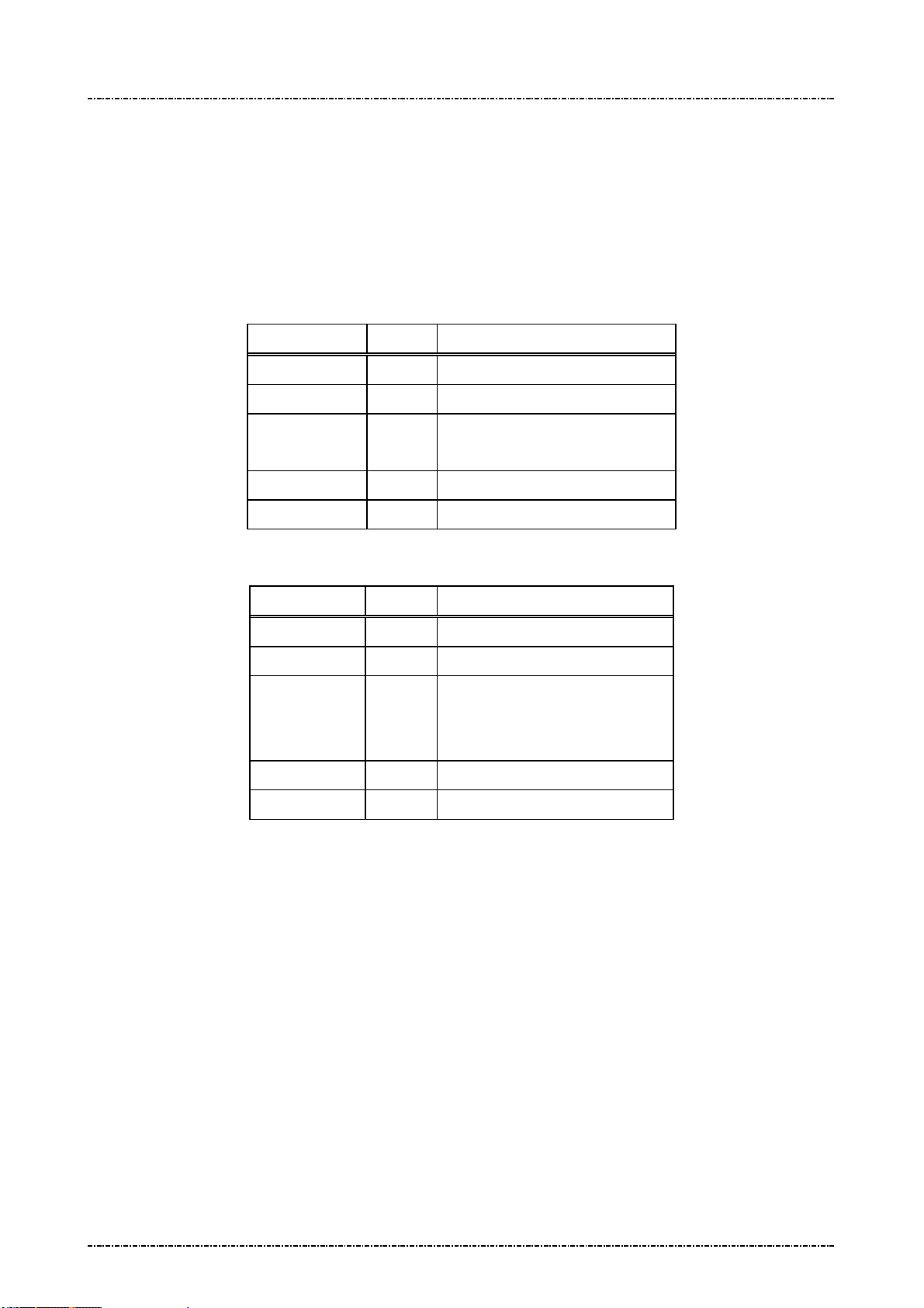
PIN Pad 791 Programmer’s Manual (PCI POS-A) UDN PM0103-U Rev. 06
Section 5 – Administration and maintenance messages 2015-04-20
Message 14 Enable/Disable Timer Display
Format: <SI>14[E/D]<SO>[LRC] (request frame)
<SI>14[Status]<SO>[LRC] (response frame)
Message length: Fixed 6 bytes.
Usage: This message is used to enable / disable PP791 system timer display.
Message element:
Request frame (HOST to PIN Pad)
Field Length Value and description
<SI> 1 <0F>
14 2 Message ID
[E/D] 1 ‘0’: Disable
‘1’: Enable
<SO> 1 <0E>
[LRC] 1 Checksum
Response frame (PIN Pad to HOST)
Field Length Value and description
<SI> 1 <0F>
14 2 Message ID
[Status] 1 ‘0’: Disabled
‘1’: Enabled
‘2’: Format Error
<SO> 1 <0E>
[LRC] 1 Checksum
Page47
Uniform Industrial Corp. Proprietary and Confidential Total 342 pages

PIN Pad 791 Programmer’s Manual (PCI POS-A) UDN PM0103-U Rev. 06
Section 5 – Administration and maintenance messages 2015-04-20
Message flow:
HOST Direction PIN Pad
Message 14
(Request frame)
<ACK> (Good LRC)
<NAK> (Bad LRC)
<EOT> (after 3 NAKs)
Message 14
(Response frame)
<ACK>/<NAK>/<EOT>
<EOT>
Page48
Uniform Industrial Corp. Proprietary and Confidential Total 342 pages
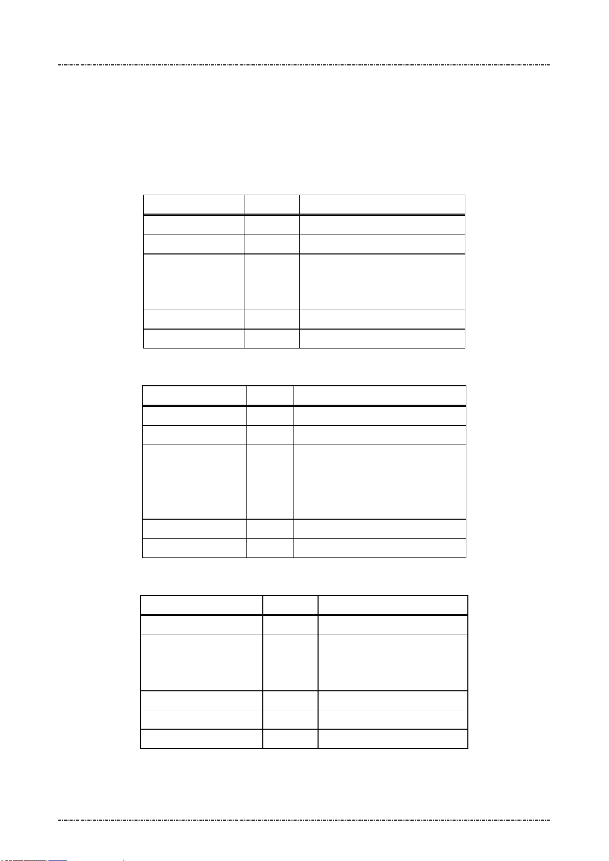
PIN Pad 791 Programmer’s Manual (PCI POS-A) UDN PM0103-U Rev. 06
Section 5 – Administration and maintenance messages 2015-04-20
Message 15 Adjust LCD Backlight Level
Format: <SI>15[contrast stepping code]<SO>[LRC]
Message length: Fixed 6 bytes.
Usage: This message will set the backlight level of LCD monitor.
Message element:
Request frame (HOST to PIN Pad)
Field Length Value and description
<SI> 1 <0F>
15 2 Message ID
[contrast
stepping
code]
<SO> 1 <0E>
[LRC] 1 Checksum
Response frame (PIN Pad to HOST)
Field Length Value and description
<SI> 1 <0F>
15 2 Message ID
[status] 1 ASCII character
<SO> 1 <0E>
[LRC] 1 Checksum
1 ASCII character
‘1’ = darkest to
‘8’ = lightest
‘1’ to ‘8’ for success (echo of contrast
stepping code).
‘F’ for operation fail
Message flow:
HOST Direction PIN Pad
Message 15 (request)
<ACK>/<NAK>/<EOT>
Page49
Uniform Industrial Corp. Proprietary and Confidential Total 342 pages
<ACK> (Good LRC)
<NAK> (Bad LRC)
<EOT> (after 3 NAKs)
Message 15 (response)
<EOT>
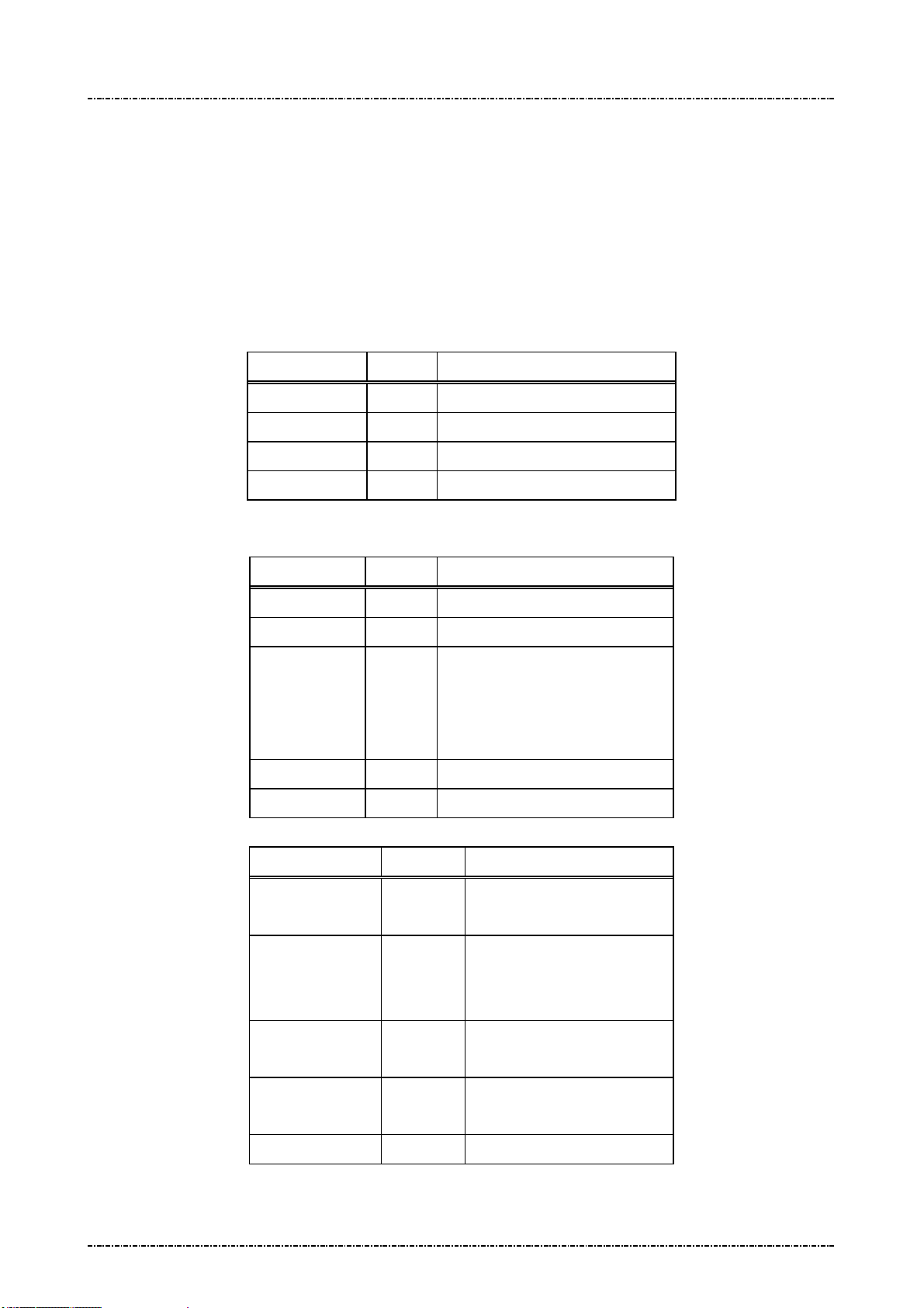
PIN Pad 791 Programmer’s Manual (PCI POS-A) UDN PM0103-U Rev. 06
Section 5 – Administration and maintenance messages 2015-04-20
Message 16 Remote self-test request
Format: <SI>16<SO>[LRC]
Message length: Fixed 5 bytes.
Usage: This message is used to ensure that the PP791 attached to the HOST is working
normally. PP791 will response an ACK (or NAK if LRC incorrect) within one second. If
multiple tests failed, response code will concatenate such as “<SI>16125<SO>”.
Message element:
Request frame (HOST to PIN Pad)
Field Length Value and description
<SI> 1 <0F>
16 2 Message ID
<SO> 1 <0E>
[LRC] 1 Checksum
Message flow:
Response frame (PIN Pad to HOST)
Field Length Value and description
<SI> 1 <0F>
16 2 Message ID
[Response] 1 .. 3 0 – Healthy
1 – RAM test fail
2 – ROM checksum fail
5 – Master keys CRC error
<SO> 1 <0E>
[LRC] 1 Checksum
HOST Direction PIN Pad
Message 16
(Request frame)
<ACK> (Good LRC)
<NAK> (Bad LRC)
<EOT> (after 3 NAKs)
<ACK>/<NAK>
/<EOT>
Page50
Uniform Industrial Corp. Proprietary and Confidential Total 342 pages
Message 16
(Response frame)
<EOT>
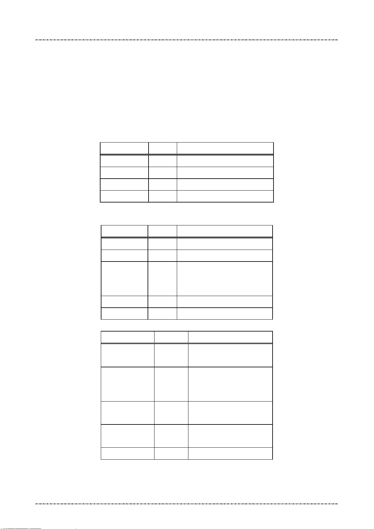
PIN Pad 791 Programmer’s Manual (PCI POS-A) UDN PM0103-U Rev. 06
Section 5 – Administration and maintenance messages 2015-04-20
Message 17 Request random number
Format: <SI>17<SO>[LRC]
Message length: Fixed 5 bytes.
Usage: This message is used to request PIN Pad to generate an 8bytes random number block.
This random number is generated by hardware TRNG that is certified with sufficient
security.
Message element:
Request frame (HOST to PIN Pad)
Field Length Value and description
<SI> 1 <0F>
17 2 Message ID
<SO> 1 <0E>
[LRC] 1 Checksum
Message flow:
Response frame (PIN Pad to HOST)
Field Length Value and description
<SI> 1 <0F>
17 2 Message ID
[RndBlk] 16 Random number block generated
by PP791.
Format: hexadecimal string.
<SO> 1 <0E>
[LRC] 1 Checksum
HOST Direction PIN Pad
Message 17
(Request frame)
<ACK> (Good LRC)
<NAK> (Bad LRC)
<EOT> (after 3 NAKs)
<ACK>/<NAK>
/<EOT>
Page51
Uniform Industrial Corp. Proprietary and Confidential Total 342 pages
Message 17
(Response frame)
<EOT>

PIN Pad 791 Programmer’s Manual (PCI POS-A) UDN PM0103-U Rev. 06
Section 5 – Administration and maintenance messages 2015-04-20
Message 18 Set PIN pad system time
Format: <SI>18[YYYY][MM][DD][W][HH][MM][SS]<SUB>[TZ Variable]<SO>[LRC]
(Request frame for setting local time and time zone)
<SI>18<SUB>[TZ Variable]<SO>[LRC]
(Request frame for setting time zone)
<SI>18[YYYY][MM][DD][W][HH][MM][SS]<SO>[LRC]
(Request frame for setting local time)
Message length: Fixed 20 bytes. Fixed 20 (set date and time only) or Variables (with time zone) bytes.
Usage: This message is used to set PP791 internal clock to display local time and for EMV
level 2 transaction log.
The syntax of time zone environment variables are same as POSIX systems. Please
be aware of the input syntax, otherwise the time zone setting will be invalid. This time
zone setting just needs to setup once, and then the environment variables will be
Message element:
stored in PP791.
Request frame for setting local time and time zone
(HOST to PIN Pad)
Field Length Value and description
<SI> 1 <0F>
18 2 Message ID
[YYYY] 4 AD year, i.e. “2014”
[MM] 2 Month, “01”~”12”
[DD] 2 Day of month, “01”~”31”
[W] 1 Day of week, “0”=Sunday, ~
“6”=Saturday
[HH] 2 Hour, “00”~”23”
[MM] 2 Minute, “00”~”59”
[SS] 2 Second, “00”~”59”
<SUB> 1 <1A>
[TZ Variable] Var. Time zone environment variable.
(For example,
send
"PST+8PDT,M3.2.0/2,M11.1.0/2"
to set Pacific time zone in the
United States)
<SO> 1 <0E>
Page52
Uniform Industrial Corp. Proprietary and Confidential Total 342 pages

PIN Pad 791 Programmer’s Manual (PCI POS-A) UDN PM0103-U Rev. 06
Section 5 – Administration and maintenance messages 2015-04-20
[LRC] 1 Checksum
Request frame for setting time zone
(HOST to PIN Pad)
Field Length Value and description
<SI> 1 <0F>
18 2 Message ID
<SUB> 1 <1A>
[TZ Variable] Var. Time zone environment variable.
<SO> 1 <0E>
[LRC] 1 Checksum
Request frame for setting local time
(HOST to PIN Pad)
Field Length Value and description
<SI> 1 <0F>
18 2 Message ID
[YYYY] 4 AD year, i.e. “2014”
[MM] 2 Month, “01”~”12”
[DD] 2 Day of month, “01”~”31”
[W] 1 Day of week, “0”=Sunday, ~
“6”=Saturday
[HH] 2 Hour, “00”~”23”
[MM] 2 Minute, “00”~”59”
[SS] 2 Second, “00”~”59”
<SO> 1 <0E>
[LRC] 1 Checksum
Response frame (PIN Pad to HOST)
Field Length Value and description
<SI> 1 <0F>
18 2 Message ID
[status] 1 0: Success
F: Failed.
<SO> 1 <0E>
[LRC] 1 Checksum
Page53
Uniform Industrial Corp. Proprietary and Confidential Total 342 pages

PIN Pad 791 Programmer’s Manual (PCI POS-A) UDN PM0103-U Rev. 06
Section 5 – Administration and maintenance messages 2015-04-20
Message flow:
HOST Direction PIN Pad
Message 18 request frame
<ACK> (Good LRC)
<NAK> (Bad LRC)
<EOT> (after 3 NAKs)
<ACK> /<NAK> /<EOT>
Message 18 Response Frame
Processing and send <EOT>
NOTE:
The followings describe that how to input a proper syntax of time zone enviorment variable.
The first format is used when there is no Daylight Saving Time in the local time zone:
std offset
The std string specifies the name of the time zone. It must be 3 ~ 6 characters long and must not contain a
leading colon, embedded digits, commas nor plus and minus signs.
The offset specifies the time value you must add to the local time to get a Coordinated Universal Time
value. It has syntax like [+|-]hh[:mm[:ss]]. This is positive if the local time zone is west of the Prime Meridian
and negative if it is east. The hour must be between 0 and 23, and the minute and seconds between 0 and
59. (for example, PST+8)
The second format is used when there is Daylight Saving Time:
std offset dst[offset],start[/time],end[/time]
The initial std and offset specify the standard time zone, as described above. The dst string and offset
specify the name and offset for the corresponding Daylight Saving Time zone. If the offset is omitted, it
defaults to one hour ahead of standard time.
The start field is when Daylight Saving Time goes into effect and the end field is when the change is made
back to standard time. The following formats are recognized for these fields:
Jn
This specifies the Julian day, with n between 1 and 365. February 29 is never counted, even in
leap years.
n
This specifies the Julian day, with n between 0 and 365. February 29 is counted in leap years.
Page54
Uniform Industrial Corp. Proprietary and Confidential Total 342 pages

PIN Pad 791 Programmer’s Manual (PCI POS-A) UDN PM0103-U Rev. 06
Section 5 – Administration and maintenance messages 2015-04-20
Mm.w.d This specifies day d of week w of month m. The day d must be between 0 (Sunday) and 6. The
week w must be between 1 and 5, week 1 is the first week in which day d occurs, and week 5
specifies the last d day in the month. The month m should be between 1 and 12.
The time fields specify when, in the local time currently in effect, the change to the other time occurs. If
omitted, the default is 02:00:00.
For example, here is how you would specify the Pacific time zone in the United States, including the
appropriate Daylight Saving Time and its dates of applicability. The normal offset from UTC is 8 hours, since
this is west of the prime meridian, the sign is positive. Summer time begins on the second Sunday in March at
2:00am, and ends on the first Sunday in Novenber at 2:00am.
PST+8PDT,M3.2.0/2,M11.1.0/2
Page55
Uniform Industrial Corp. Proprietary and Confidential Total 342 pages
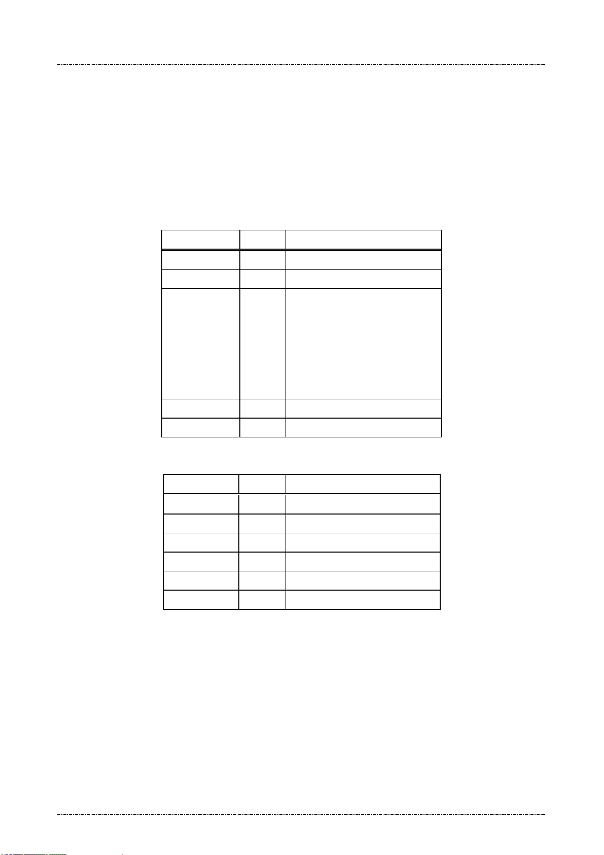
PIN Pad 791 Programmer’s Manual (PCI POS-A) UDN PM0103-U Rev. 06
Section 5 – Administration and maintenance messages 2015-04-20
Message 19 Query Firmware Version
Format: <SI>19[part]<SO>[LRC] (request frame)
<SI>19.[Version] <SO>[LRC] (response frame)
Message length: Fixed 6 bytes (request frame) / Variable (response frame).
Usage: This message is used to query PP791 firmware version number and firmware check
sum value.
Message element:
Request frame (HOST to PIN Pad)
Field Length Value and description
<SI> 1 <0F>
19 2 Message ID
[part] 1 Firmware Part number
1: Uboot
2: Kernel
3: Root File System (RFS)
4: System Manager (SysMgr)
5: PP791 App.
<SO> 1 <0E>
[LRC] 1 Checksum
Response frame (PIN Pad to HOST)
Field Length Value and description
<SI> 1 <0F>
19 2 Message ID
. 1 <2E>, field separator
[Version] Var. Version string (ASCII string)
<SO> 1 <0E>
[LRC] 1 Checksum
Page56
Uniform Industrial Corp. Proprietary and Confidential Total 342 pages

PIN Pad 791 Programmer’s Manual (PCI POS-A) UDN PM0103-U Rev. 06
Section 5 – Administration and maintenance messages 2015-04-20
Message flow:
HOST Direction PIN Pad
Message 19
(Request frame)
<ACK> (Good LRC)
<NAK> (Bad LRC)
<EOT> (after 3 NAKs)
Message 19
(Response frame)
<ACK>/<NAK>/<EOT>
<EOT>
Page57
Uniform Industrial Corp. Proprietary and Confidential Total 342 pages

PIN Pad 791 Programmer’s Manual (PCI POS-A) UDN PM0103-U Rev. 06
Section 5 – Administration and maintenance messages 2015-04-20
Message 1C Query Hardware Capability
Format: <SI>1C<SO>[LRC] (request frame)
<SI>1C[string]<SO>[LRC] (response frame)
Message length: Fixed 5 bytes (request). Variable (response).
Usage: This message is used to query the peripheral capability of PP791.
Message element:
Request frame (HOST to PIN Pad)
Field Length Value and description
<SI> 1 <0F>
1C 2 Message ID
<SO> 1 <0E>
[LRC] 1 Checksum
Response frame (PIN Pad to HOST)
Message flow:
Field Length Value and description
<SI> 1 <0F>
1C 2 Message ID
[string] Variable <1C>[HW1]<1C>[HW2]......
Possible string:
“ICC”: Smart card reader.
“SAM”: Security Access Module Slot.
“MSR”: Magnetic Stripe Reader.
“0” Pure PIN pad without peripherals.
<SO> 1 <0E>
[LRC] 1 Checksum
HOST Direction PIN Pad
Message 1C
(Request frame)
<ACK>/<NAK>/<EOT>
Page58
Uniform Industrial Corp. Proprietary and Confidential Total 342 pages
<ACK> (Good LRC)
<NAK> (Bad LRC)
<EOT> (after 3 NAKs)
Message 1C
(Response frame)
<EOT>

PIN Pad 791 Programmer’s Manual (PCI POS-A) UDN PM0103-U Rev. 06
Section 5 – Administration and maintenance messages 2015-04-20
Message 1F Query Usable Prompt Table
Format: <SI>1F<SO>[LRC] (request frame)
<SI>1F[Prompt_List]<SO>[LRC] (response frame)
Message length: Fixed 6 bytes (request frame); Variable (response frame).
Usage: This message is used to query usable PP791 prompt message table list. List will be
represented as 2-character country code defined by ISO 3166.
Message element:
Request frame (HOST to PIN Pad)
Field Length Value and description
<SI> 1 <0F>
1F 2 Message ID
<SO> 1 <0E>
[LRC] 1 Checksum
Message flow:
Response frame (PIN Pad to HOST)
Field Length Value and description
<SI> 1 <0F>
1F 2 Message ID
[Prompt List] 20 Format:
[active country code]
<FS> [country code0]
….
<FS> [country code5]
<SO> 1 <0E>
[LRC] 1 Checksum
HOST Direction PIN Pad
Message 1F
(Request frame)
<ACK>/<NAK>/<EOT>
Page59
Uniform Industrial Corp. Proprietary and Confidential Total 342 pages
<ACK> (Good LRC)
<NAK> (Bad LRC)
<EOT> (after 3 NAKs)
Message 1F
(Response frame)

PIN Pad 791 Programmer’s Manual (PCI POS-A) UDN PM0103-U Rev. 06
Section 5 – Administration and maintenance messages 2015-04-20
<EOT>
Page60
Uniform Industrial Corp. Proprietary and Confidential Total 342 pages

PIN Pad 791 Programmer’s Manual (PCI POS-A) UDN PM0103-U Rev. 06
Section 5 – Administration and maintenance messages 2015-04-20
Message 1J Turn ON/OFF LCD Backlight
Format: <SI>1J[option]<SO>[LRC]
Message length: Fixed 6 bytes.
Usage: This message can control the global backlight ON or OFF for the LCD of PP791 with
backlight option. By default, PP791 will turn on its LCD backlight when it receives PIN
entry or clear text entry message such as 70 or Z50, and turn it off when those
functions exits. With message “1J1”, the PP791 will keep LCD backlight turned ON
until “1J0” is issued.
Message element:
Request frame (HOST to PIN Pad)
Field Length Value and description
<SI> 1 <0F>
1J 2 Message ID
[option] 1 ASCII character
‘0’: Turn off LCD backlight
‘1’: Turn on LCD backlight
<SO> 1 <0E>
[LRC] 1 Checksum
Response frame (PIN Pad to HOST)
Field Length Value and description
<SI> 1 <0F>
1J 2 Message ID
[status] 1 ASCII character
‘0’: Turn off LCD backlight
‘1’: Turn on LCD backlight
<SO> 1 <0E>
[LRC] 1 Checksum
Page61
Uniform Industrial Corp. Proprietary and Confidential Total 342 pages

PIN Pad 791 Programmer’s Manual (PCI POS-A) UDN PM0103-U Rev. 06
Section 5 – Administration and maintenance messages 2015-04-20
Message flow:
HOST Direction PIN Pad
Message 1J
<ACK> (Good LRC)
<NAK> (Bad LRC)
<EOT> (after 3 NAKs)
Message 1J
(Response frame)
<ACK>/
<NAK>/
<EOT>
<EOT>
LCD backlight turned ON/OFF
Page62
Uniform Industrial Corp. Proprietary and Confidential Total 342 pages

PIN Pad 791 Programmer’s Manual (PCI POS-A) UDN PM0103-U Rev. 06
Section 5 – Administration and maintenance messages 2015-04-20
Message 1KTurn ON/OFF LCD Power-save mode
Format: <SI>1K[option]<SO>[LRC]
Message length: Fixed 6 bytes.
Usage: For power consumption saving, this message can make PP791 turns the backlight
level to darker after several seconds automatically. The backlight level will return to the
value set before when a key strobe is pressed, a message about PIN entry or key entry
is received.
Message element:
Request frame (HOST to PIN Pad)
Field Length Value and description
<SI> 1 <0F>
1K 2 Message ID
[option] 1 ASCII character
‘0’: Turn off LCD power-save mode
‘1’: Turn on LCD power-save mode
<SO> 1 <0E>
[LRC] 1 Checksum
Response frame (PIN Pad to HOST)
Field Length Value and description
<SI> 1 <0F>
1K 2 Message ID
[status] 1 ASCII character
‘0’: Turn off LCD power-save mode
‘1’: Turn on LCD power-save mode
<SO> 1 <0E>
[LRC] 1 Checksum
Page63
Uniform Industrial Corp. Proprietary and Confidential Total 342 pages

PIN Pad 791 Programmer’s Manual (PCI POS-A) UDN PM0103-U Rev. 06
Section 5 – Administration and maintenance messages 2015-04-20
Message flow:
HOST Direction PIN Pad
Message 1K
<ACK> (Good LRC)
<NAK> (Bad LRC)
<EOT> (after 3 NAKs)
Message 1K
(Response frame)
<ACK>/
<NAK>/
<EOT>
<EOT>
LCD power-save mode turned ON/OFF
Page64
Uniform Industrial Corp. Proprietary and Confidential Total 342 pages
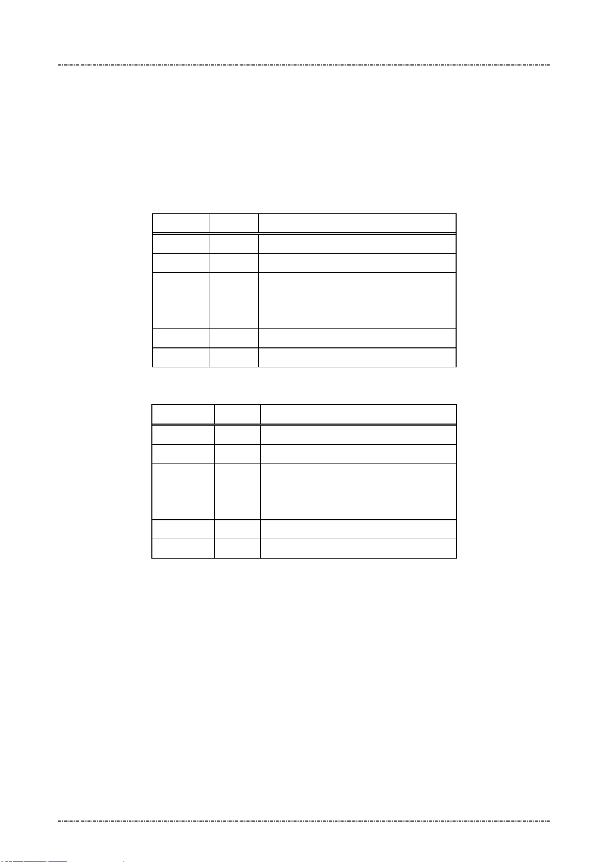
PIN Pad 791 Programmer’s Manual (PCI POS-A) UDN PM0103-U Rev. 06
Section 5 – Administration and maintenance messages 2015-04-20
Message 1M Setup Keypad Beeper
Format: <SI>1M[option]<SO>[LRC]
Message length: Fixed 6 bytes.
Usage: This message is used to turn on or turn off beeper when the keypad is pressing.
Message element:
Request frame (HOST to PIN Pad)
Field Length Value and description
<SI> 1 <0F>
1M 2 Message ID
[option] 1 ASCII character
‘0’: Disable keypad beeper.
‘1’: Enable keypad beeper.
<SO> 1 <0E>
[LRC] 1 Checksum
Response frame (PIN Pad to HOST)
Field Length Value and description
<SI> 1 <0F>
1M 2 Message ID
[status] 1 ASCII character
‘0’: Keypad beeper disabled.
‘1’: Keypad beeper enabled.
<SO> 1 <0E>
[LRC] 1 Checksum
Page65
Uniform Industrial Corp. Proprietary and Confidential Total 342 pages

PIN Pad 791 Programmer’s Manual (PCI POS-A) UDN PM0103-U Rev. 06
Section 5 – Administration and maintenance messages 2015-04-20
Message flow:
HOST Direction PIN Pad
Message 1M
<ACK> (Good LRC)
<NAK> (Bad LRC)
<EOT> (after 3 NAKs)
Message 1M
(Response frame)
<ACK>/
<NAK>/
<EOT>
<EOT>
Page66
Uniform Industrial Corp. Proprietary and Confidential Total 342 pages

PIN Pad 791 Programmer’s Manual (PCI POS-A) UDN PM0103-U Rev. 06
Section 6 – Contact EMV Level 2 transaction messages 2015-04-20
Section 6 Contact EMV Level 2 transaction messages
EMV Level2 transaction messages are divided into 2 groups. One is EMV-configuration data operation
messages (T01, T03, T05, T07, T09, T0B) and the other one is EMV-transaction messages (T11, T13, T15,
T17, T19, T1C, T21, T25, T27, T29).
The ICC EMV transaction messages issuing sequence is control by PIN pad, an invalid sequence will
terminate ICC EMV transaction. At the first of ICC EMV transaction, user has to issue messages T11 to make
PIN pad negotiate with card and generate a candidate list of EMV-application that supported by PIN pad and
card both, and then select a highest priority one automatically or selected by user (according to the terminal
configuration data installed in PIN pad), finally return the EMV-application name. Message T15 is used for
terminal-side to transmit transaction information such as amount and then PIN pad do a complete transaction
with card if the transaction needs not to be authorized online. Terminal can issue message T1D to transmit
additional transaction data into PIN pad for ICC EMV transaction, such as online response data, magnetic
stripe card track data. Message T17 is applied if the transaction needs to be authorized online, terminal-side
will transmit necessary information via this message to PIN pad to continue the rest steps of transaction. If
the response from host contains issuer script (see EMV), terminal-side applies message T19 to input these
scripts into PIN pad and PIN pad will issue these scripts at appropriate time to card. Message T1C is used to
terminate an ICC EMV transaction. Finally, message T21 is used for terminal-side to get the transaction
information through EMV transaction.
Terminal can apply Txx messages to handle a complete ICC EMV transaction except that the transaction
must be changed to magnetic stripe card processing. According to EMV rule, if terminal fails to read IC card,
the transaction could be change to magnetic stripe card transaction. Because of different types of magnetic
stripe card, the magnetic stripe card processing should be taken by terminal. Terminal could issue message
Q1 provided by PIN pad to make user swipe his card and then issue message 70 to complete a magnetic
stripe card transaction. In this situation, terminal will get response of T11 message that indicates an failed IC
card read, terminal should then issue message T1D, T15 and T17 to PIN pad for batch data capture. The flow
chart for changing to magnetic stripe card processing could be referred in “Overall Contact EMV level 2
transaction flow reference” section.
Page67
Uniform Industrial Corp. Proprietary and Confidential Total 342 pages

PIN Pad 791 Programmer’s Manual (PCI POS-A) UDN PM0103-U Rev. 06
Section 6 – Contact EMV Level 2 transaction messages 2015-04-20
The meaning of error code in the [Err Message] are listed below:
Error Code Error Description
00000003 Service not accepted.
00000F9B Store configuration data error.
8FFF0001 Out of memory.
8FFF0002 Parameter error.
8FFFFF02 Tag’s data format error.
8FFFFF03 Some mandatory tags are not configured well.
8FFFFFF0 Command format error.
8FFFFFF1 The sequence of EMV transaction command is error.
8FFFFFF2 Terminal fundamental data is missing.
8FFFFFF3 Authentication failed.
8FFFFF1A Authentication key expired.
8FFFFF1B Terminal configuration data is missing.
8FFFFF1C No configuration data of EMV application or the data is missing.
8FFFFFF4 The storage space of batch data capture is full.
8FFFFFF5 No terminal configuration data, EMV application configuration data or CA public key.
A2000001 Application initial conditions are not satisfied.
A2000002 The generated cryptogram is not allowed.
A2000007 The instruction ID of the specified is not recognized.
A200000A The type to request application cryptogram is incorrect.
A200000C The status response (SW1 SW2) is other than ‘9000’.
A200000D The Generate AC command is called more than 2 times in the current transaction.
A200000E The AIP mandatory data is missing in response data from card.
A200000F The AFL mandatory data is missing in response data from card.
A2000010 The response template from card isn't correct.
A2000011 The format of AFL is incorrect.
A2000013 A redundant data output from card is not allowed.
A2000014 Missing mandatory data in response data from card.
EFFFFFFF EMV transaction cancelled.
DFFFFFFF EMV forced abort.
Page68
Uniform Industrial Corp. Proprietary and Confidential Total 342 pages
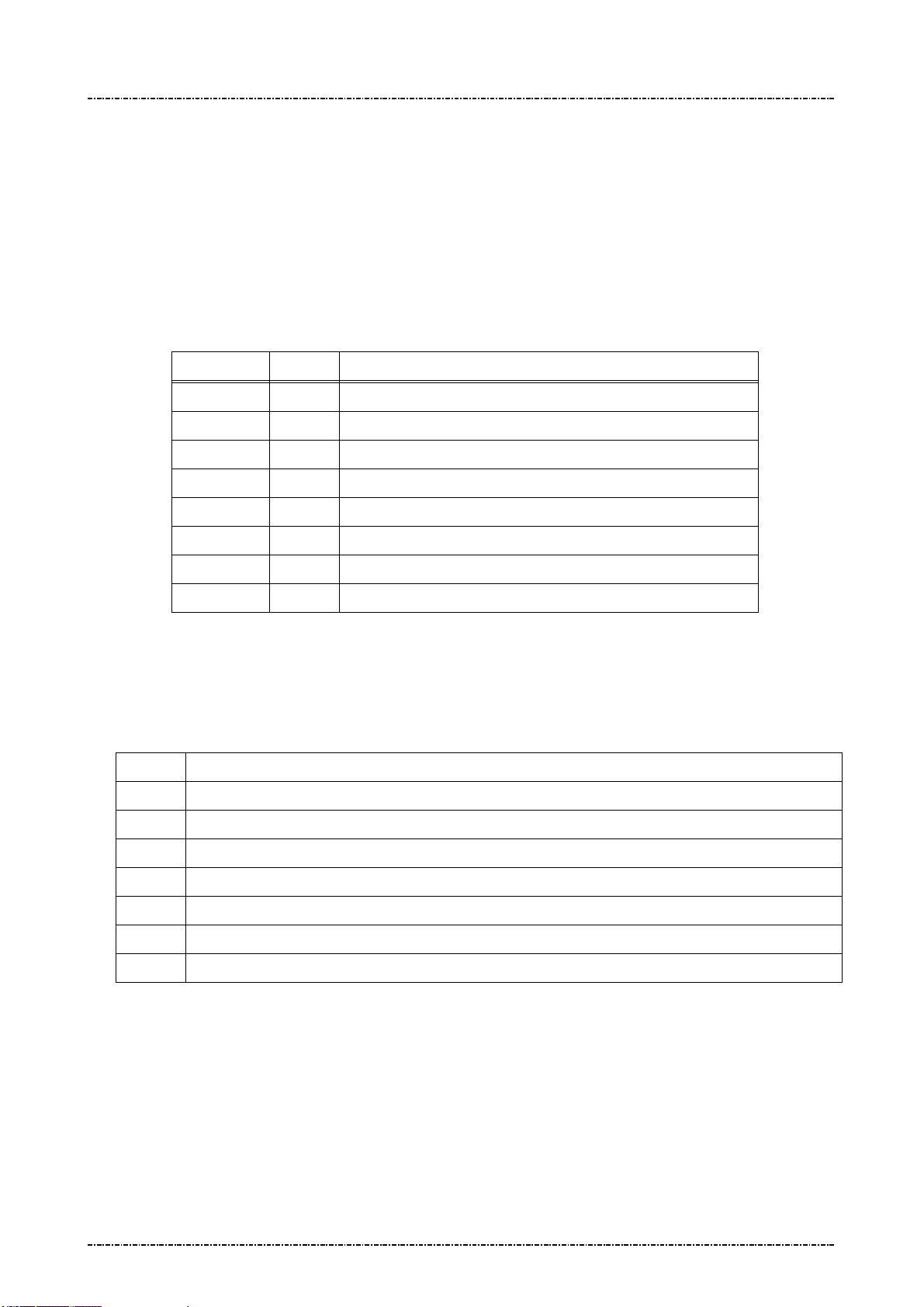
PIN Pad 791 Programmer’s Manual (PCI POS-A) UDN PM0103-U Rev. 06
Section 6 – Contact EMV Level 2 transaction messages 2015-04-20
Message T01 Terminal Configuration Setup
Format: <STX>T01[Pkt No.][Total Pkts]<SUB>[DO]<ETX>[LRC]
Message length: Variable.
Usage: Host can use this command to send terminal configuration data to PIN pad, this
command can be sent many times. PIN pad will save those data inside and apply
those data when do the transaction. PIN pad will send the message T02 (Terminal
Configuration Setup Response) to host.
Message element:
Field Length
<STX> 1 <02>
T01 3 Message ID
Pkt No. 1 Decimal. Packet sequence number (1 ~ 9)(ex. 2)
Total Pkts 1 Decimal. Total packets (1~9)(ex. 8).
<SUB> 1 <1A, Optional, only if [DO] is existed
DO Var. Data Object, format as below
<ETX> 1 <03>
[LRC] 1 Checksum
Data Object Format: each data object is delimited by <SUB>, and each field inside each data
object is delimited by <FS>.
Data Format: (Please also refer to EMV 4.3 BOOK3, section 4.3)
Format
1 a - Alphabetic data (a ~z, A~Z)
Value and description
Description
2 b - unsigned binary numbers or bit combinations
3 an - Alphanumeric data (a ~z, A~Z, 0~9)
4 ans - Alphanumeric Special data (Characters defined in ISO8859)
5 cn - Compressed numeric data (0~9, left justify, pad hexadecimal ‘F’s. Ex. 12 34 56 12 3F FF)
6 n - Numeric data (0~9, right justify, pad leading hexadecimal zeroes. Ex. 00 00 00 01 23 45)
7 var - Variable data (Any bit combination)
Note. User has to obey the restriction specified in EMV 4.3 BOOK3, Annex A and Appendix D of
this document to load configuration data. PIN pad will check if the length of each
configuration data item is consistent. Any inconsistent data item will make data loading
fail.
Note. If the data format is ‘2’ (binary), ‘5’(compressed numeric), ‘6’(numeric) or ‘7’(variable data),
it can not be allocated in message T01 directly. It should be transferred into hexadecimal
string and then allocated in message T01.
Page69
Uniform Industrial Corp. Proprietary and Confidential Total 342 pages

PIN Pad 791 Programmer’s Manual (PCI POS-A) UDN PM0103-U Rev. 06
Section 6 – Contact EMV Level 2 transaction messages 2015-04-20
Example: (Clear the terminal configuration data and then setup new data.)
Merchant Category Code: 0000 (Numerical)
Terminal ID: SmartPOS (Ascii)
UI Capability: 0x01 (binary)
<STX>T0111<SUB>9f15<FS>6<FS>0000<SUB>9f1c<FS>3<FS>SmartPOS<SUB>
50000002<FS>2<FS>01<ETX>[LRC]
Special Tag for PIN pad: 0x50000001, 0x50000002
Name Description Format Tag Length
Terminal UI
Capability
MSR
Processing
Batch Tag
List
Online PIN
Block Tag
Define
Online PIN
0: Make PIN pad selects the highest
priority application and ask user’s
confirmation.
1:Make PIN pad provides a list of
candidate applications.
PIN pad will store transaction data
according to the tag list while the
transaction is performed as MSR
processing. Ex, for tag list (829F365F3
09F399F029F03), PIN pad will store
transaction data of tag number 0x82,
0x9F36, 0x5F30, 0x9F39, 0x9F02 and
0x9F03.
User can define new tag number for
online PIN block.
User can define new tag number for
b 50000002 1
b 50000003 var
b 50000004 1~4
b 50000005 1~4
Key Tag
online PIN key.
Define
These data object are defined in EMV 4.3 BOOK3, Annex A without tag values. The tag values are
defined by UIC.
NOTE.
In order to make PIN pad accept new defined tag (Online PIN Block Tag, Online PIN Key Tag),
terminal should issue message T07 to add the new tag into tag table inside PIN pad. For example, if
terminal wants to define new tag 0xDF01 and 0xDF02 for PIN block tag and PIN key tag, it must
issue message T07 with value “0<SUB>DF01<FS>202020<SUB>DF02<FS>202020” to add new tag
number into tag table inside PIN pad. Finally, issue message T01 with value “50000004
<FS>2<FS>DF01<SUB>50000005<FS>2<FS>DF02”
Page70
Uniform Industrial Corp. Proprietary and Confidential Total 342 pages
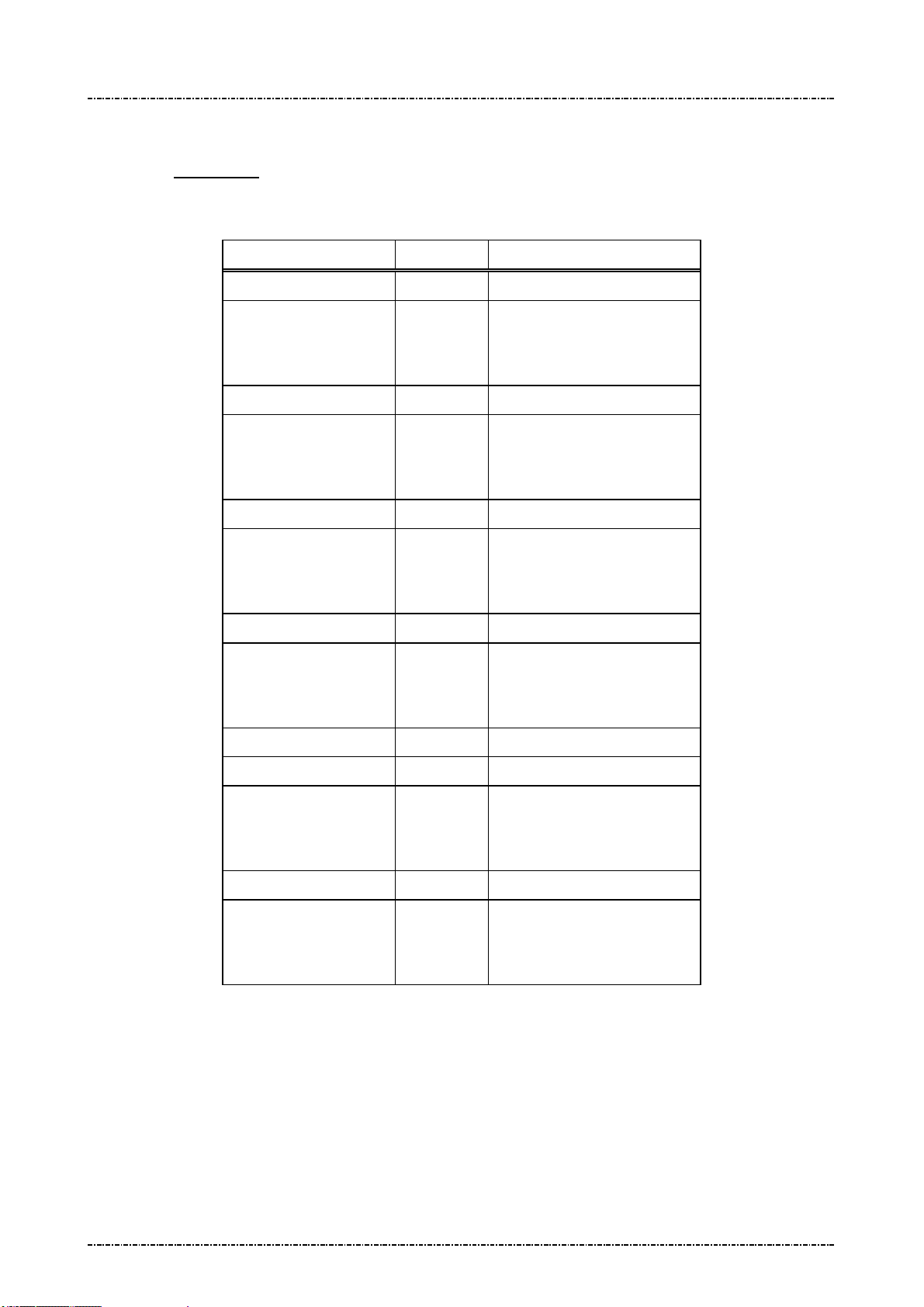
PIN Pad 791 Programmer’s Manual (PCI POS-A) UDN PM0103-U Rev. 06
Section 6 – Contact EMV Level 2 transaction messages 2015-04-20
PIN pad will check if terminal downloads minimum set of terminal-related information into PIN
pad. The download process will be failed if there is not enough data in this message. Please
refer to Appendix E for minimum set of terminal-related data
Message flow:
HOST Direction PIN pad
1st Message T01
<ACK> (Good LRC)
<NAK> (Bad LRC)
<EOT> (after 3 NAKs)
2nd Message T01
<ACK> (Good LRC)
<NAK> (Bad LRC)
<EOT> (after 3 NAKs)
<ACK> (Good LRC)
<NAK> (Bad LRC)
<EOT> (after 3 NAKs)
1st Message T02
<ACK> (Good LRC)
<NAK> (Bad LRC)
<EOT> (after 3 NAKs)
2nd Message T02
… … …
Last one Message T01
<ACK> (Good LRC)
<NAK> (Bad LRC)
<EOT> (after 3 NAKs)
<ACK> (Good LRC)
<NAK> (Bad LRC)
Last one Message T02
<EOT> (after 3 NAKs)
Page71
Uniform Industrial Corp. Proprietary and Confidential Total 342 pages

PIN Pad 791 Programmer’s Manual (PCI POS-A) UDN PM0103-U Rev. 06
Section 6 – Contact EMV Level 2 transaction messages 2015-04-20
Message T02 Terminal Configuration Setup Response
Format: <STX>T02[Res][Reason][Err Msg][Err Tag Number]<ETX>[LRC]
Message length: Variable.
Usage: The response message of command T01.
Message element:
Field Length Value and description
<STX> 1 <02>
T02 3 Message ID
Res 1 ‘0’: Ok,
‘1’: Fail
Reason 1 <Optional, if Res = ‘1’>
‘1’: Fatal Error
‘2’: Format Error
‘3’: Invalid Data Object format.
‘4’: Invalid Tag value
Err Message 8 Optional, if Reason = ‘1’, Hex decimal string
Err Tag Number Var. Optional, if Reason = ‘3’ or ‘4’, Hex decimal
string
<ETX> 1 <03>
[LRC] 1 Checksum
Message flow: Please refer to message T01.
Page72
Uniform Industrial Corp. Proprietary and Confidential Total 342 pages

PIN Pad 791 Programmer’s Manual (PCI POS-A) UDN PM0103-U Rev. 06
Section 6 – Contact EMV Level 2 transaction messages 2015-04-20
Message T03 Certification Authority Public Key Setup
Format: <STX>T03[Op code][RID][PKI][Hash Algo][Hash][PK Algo][PK Leng]
[PK Exponent]<ETX>[LRC]
<STX>T03[Op code][PK Modulus]<ETX>
Message length: Variable.
Usage: Host can use this command to send the Certification Authority Public key data to
PIN pad, each command can only setup one key but this command can be sent many
times. PIN pad will save those key data inside and use those data when do the
transaction. PIN pad will send the message T04 (Certification Authority Public Key
Setup Response) to host. The data installed into PIN pad via this message, PIN pad
will save it in internal storage structure with a name same as concatenation of value in
[RID] and [PKI] fields. Ex. value in [RID] field is “A000000003”, value in [PKI] filed is
“90”, PIN pad will save these data and give an ID as “A00000000390”.
Message element:
1st Packet (Load RSA public key):
Field Length Value and description
<STX> 1 <02>
T03 3 Message ID
Op code 1 1: Load first part of RSA public key
RID 10
PKI 2 Public Key Index, hexadecimal string. (Refer to
Hash
Algorithm
Hash 40 Hash checksum, hexadecimal
2 Hash Algorithm Index, hexadecimal string
Hexadecimal string, the left 5 bytes of Registered
Application Provider ID
EMV 4.3, tag ‘9F22’)
‘01’: SHA-1. Now, PIN pad accepts only ‘01’.
Sha1(PKModules)
or
Sha1(RID+PKI+PKModules+PKExp)
PK
Algorithm
PK Leng 2 Public Key size, hexadecimalstring, for example:
PK
Exponent
Page73
Uniform Industrial Corp. Proprietary and Confidential Total 342 pages
2 Public Key Algorithm, hexadecimal string
‘01’: RSA digital signature. Now, PIN pad accepts
only ‘01’.
‘80’ = 128 bytes = 1024 bits
1 Public Key Exponent’s size, hexadecimal
‘1’: 3
‘2’: 216+1

PIN Pad 791 Programmer’s Manual (PCI POS-A) UDN PM0103-U Rev. 06
Section 6 – Contact EMV Level 2 transaction messages 2015-04-20
<ETX> 1 <03>
[LRC] 1 Checksum
2nd Packet (Load RSA public key):
Field Length Value and description
<STX> 1 <02>
T03 3 Message ID
Op code 1 2: Load second part of RSA public key
Message flow:
PK
Modulus
Var Public Key Modulus, presented in
hexadecimal, data length = 2*[PK length]
<ETX> 1 <03>
[LRC] 1 Checksum
HOST Direction PIN pad
1st Message T03
<ACK> (Good LRC)
<NAK> (Bad LRC)
<EOT> (after 3 NAKs)
1st CA Public Key Setup
Response Message T04
<ACK> (Good LRC)
<NAK> (Bad LRC)
<EOT> (after 3 NAKs)
2nd Message T03
<ACK> (Good LRC)
<NAK> (Bad LRC)
<EOT> (after 3 NAKs)
2nd CA Public Key Setup
Response Message T04
<ACK> (Good LRC)
<NAK> (Bad LRC)
<EOT> (after 3 NAKs)
Page74
Uniform Industrial Corp. Proprietary and Confidential Total 342 pages
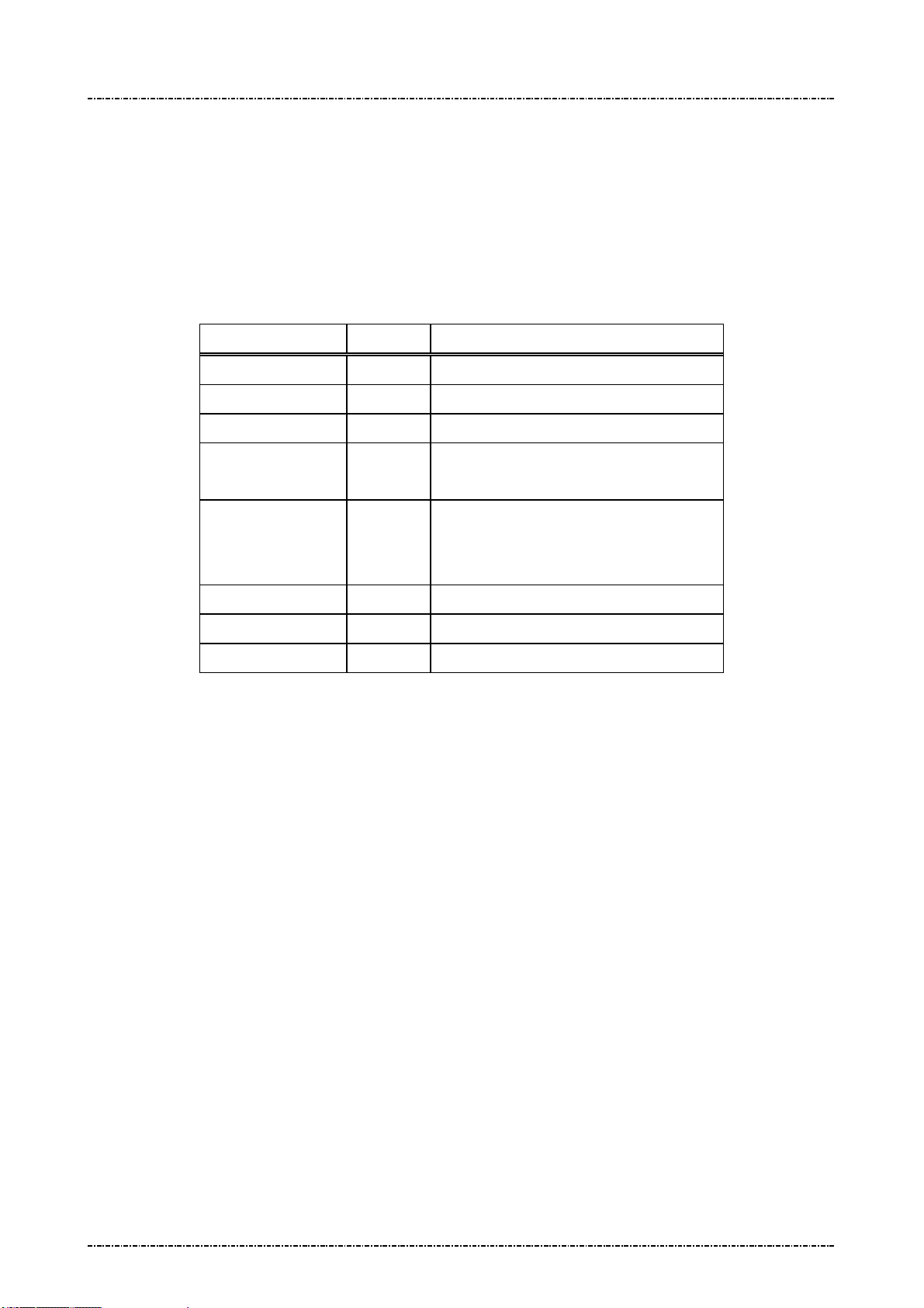
PIN Pad 791 Programmer’s Manual (PCI POS-A) UDN PM0103-U Rev. 06
Section 6 – Contact EMV Level 2 transaction messages 2015-04-20
Message T04 Certification Authority Public Key Setup Response
Format: <STX>T04[Sequence][Res][Reason][Err Msg]<ETX>[LRC]
Message length: Variable.
Usage: The response message of command T03.
Message element:
1st, 2nd Packet:
Field Length Value and description
<STX> 1 <02>
T04 3 Message ID
Sequence 1 1 / 2 (first/second part of RSA public key)
Res 1 ‘0’: Ok,
‘1’: Fail
Reason 1 ‘1’: Fatal Error
Err Message 8 Optional, if Reason = ‘1’Hex String
<ETX> 1 <03>
[LRC] 1 Checksum
Message flow: Please refer to message T03.
‘2’: Format Error
‘3’: Authentication Fail
Page75
Uniform Industrial Corp. Proprietary and Confidential Total 342 pages

PIN Pad 791 Programmer’s Manual (PCI POS-A) UDN PM0103-U Rev. 06
Section 6 – Contact EMV Level 2 transaction messages 2015-04-20
Message T05 EMV Application Configuration Setup
Format: <STX>T05[Pkt No.][Total Pkts]<SUB>[AID]<SUB>[DO]<ETX>[LRC]
<STX>T05[Pkt No.][Total Pkts]<SUB>[DO]<ETX>[LRC]
Message length: Variable.
Usage: Host can use this command to send the EMV application configuration data to PIN
pad, this command can be sent many times but each command is only for one
application. PIN pad will save those data inside and use those data when do the
transaction. PIN pad will send the message T06 (EMV Application Configuration Setup
Response) to host. The data installed into PIN pad via this message, PIN pad will save
it in internal storage structure with a name same as in [AID] field.
Message element:
1st Message:
Field Length
<STX> 1 <02>
T05 3 Message ID
Pkt No. 1 Decimal. Packet sequence number (1 ~ 9)
Total Pkts 1 Decimal. Total packets (1~9)(ex. 8).
<SUB> 1 Optional, if Pkt No is 1 <1A>
AID 10~32 Optional, if Pkt No is 1. EMV Application ID, refer to EMV 4.3
<SUB> 1 Optional, only if [DO] is existed
DO Var. Data Object, format as below
<ETX> 1 <03>
[LRC] 1 Checksum
Rest of Message (If there are 2 more messages):
Field Length
<STX> 1 <02>
T05 3 Message ID
Pkt No. 1 Decimal. Packet sequence number (1 ~ 9)
Value and description
Value and description
Total Pkts 1 Decimal. Total packets (1~9)(ex. 8).
<SUB> 1 Optional, only if [DO] is existed
DO Var. Data Object, format as below
<ETX> 1 <03>
[LRC] 1 Checksum
Page76
Uniform Industrial Corp. Proprietary and Confidential Total 342 pages

PIN Pad 791 Programmer’s Manual (PCI POS-A) UDN PM0103-U Rev. 06
Section 6 – Contact EMV Level 2 transaction messages 2015-04-20
Data Format: (Please also refer to EMV 4.3 BOOK3, section 4.3)
Format
Description
1 a - Alphabetic data (a ~z, A~Z)
2 b - unsigned binary numbers or bit combinations
3 an - Alphanumeric data (a ~z, A~Z, 0~9)
4 ans - Alphanumeric Special data (Characters defined in ISO8859)
5 cn - Compressed numeric data (0~9, left justify, pad hexadecimal ‘F’s. Ex. 12 34 56 12 3F FF)
6 n - Numeric data (0~9, right justify, pad leading hexadecimal zeroes. Ex. 00 00 00 01 23 45)
7 var - Variable data (Any bit combination)
Note. User has to obey the restriction specified in EMV 4.3 BOOK3, Annex A and Appendix D of
this document to load configuration data. PIN pad will check if the length of each
configuration data item is consistent. Any inconsistent data item will make data loading
fail.
Note. If the data format is ‘2’ (binary), ‘5’(compressed numeric), ‘6’(numeric) or ‘7’(variable data),
it can not be allocated in message T05 directly. It should be transfer into hexadecimal
string and then allocated in message T05.
Example:
Default TDOL: 97 07 9f 02 06 95 05 9b 02 (binary)
Threshold Value for Biased Random Selection: 00 00 00 00 40 00(numerical)
Max. Target percentage to be used for Biased Random selection: 100 (decimal) / 0x46 (binary)
<STX>T0511<SUB>A00000031010<SUB>97<FS>2<FS>97079f020695059b02
<SUB>40000004<FS>6<FS>000000004000 <SUB>40000006<FS>2<FS>46<ETX>[LRC]
PIN pad saves these data and give an ID as “A00000031010” to this group of data.
Special Tag for PIN pad: 0x40000001, 0x40000004, 0x40000005, 0x40000006, 0x40000007,
0x40000008, 0x40000009.
Name Description Format Tag Length
Application Selection Indicator See below n 40000001 1
Threshold Value for Biased
See below n 40000004 6
Random Selection
Target Percentage to be used
See below b 40000005 1
for Biased Random Selection
Maximum Target Percentage to
See below b 40000006 1
be used for Biased Random
Selection
Page77
Uniform Industrial Corp. Proprietary and Confidential Total 342 pages

PIN Pad 791 Programmer’s Manual (PCI POS-A) UDN PM0103-U Rev. 06
Section 6 – Contact EMV Level 2 transaction messages 2015-04-20
Terminal Action Code - Default See below b 40000007 5
Terminal Action Code - Denial See below b 40000008 5
Terminal Action Code - Online See below b 40000009 5
Data Tags required in Online
See below b 4000000A var.
message (ARQC)
Data tags required in reversal
See below b 4000000D var.
message
Data tags for batch data capture See below b 40000010 var.
ARC Approve See below b 4000001A var.
ARC Decline See below b 4000001B var.
ARC Referral See below b 4000001C var.
These data object are defined in EMV 4.3 BOOK3, Annex A without tag values. The tag values are
defined by PIN pad.
Page78
Uniform Industrial Corp. Proprietary and Confidential Total 342 pages

PIN Pad 791 Programmer’s Manual (PCI POS-A) UDN PM0103-U Rev. 06
Section 6 – Contact EMV Level 2 transaction messages 2015-04-20
Message flow:
HOST Direction PIN pad
1st Message T05
<ACK> (Good LRC)
<NAK> (Bad LRC)
<EOT> (after 3 NAKs)
2nd Message T05
<ACK> (Good LRC)
<NAK> (Bad LRC)
<ACK> (Good LRC)
<NAK> (Bad LRC)
<EOT> (after 3 NAKs)
1st Message T06
<ACK> (Good LRC)
<NAK> (Bad LRC)
<EOT> (after 3 NAKs)
Application Select Response.
2nd Message T06
<EOT> (after 3 NAKs)
… … …
Last one Message T05
<ACK> (Good LRC)
<NAK> (Bad LRC)
<EOT> (after 3 NAKs)
Application Select Response.
Last one Message T06
<ACK> (Good LRC)
<NAK> (Bad LRC)
<EOT> (after 3 NAKs)
PIN pad will check if terminal downloads minimum set of EMV Application-related information into PIN
pad. The download process will be failed if there is not enough data in this message. Please refer to
Appendix E for minimum set of EMV Application -related data
Page79
Uniform Industrial Corp. Proprietary and Confidential Total 342 pages

PIN Pad 791 Programmer’s Manual (PCI POS-A) UDN PM0103-U Rev. 06
Section 6 – Contact EMV Level 2 transaction messages 2015-04-20
Message T06 EMV Application Configuration Setup Response
Format: <STX>T06[Res][Reason][Err Msg][Err Tag Number]<ETX>[LRC]
Message length: Variable.
Usage: The response message of command T05.
Message element:
Message flow: Please refer to message T05.
Field Length Value and description
<STX> 1 <02>
T06 3 Message ID
Res 1 ‘0’: Ok,
Reason 1 ‘1’: Fatal Error
Err Message 8 Optional, if Reason = ‘1’Hex String
Err Tag Number Var. Optional, if Reason = ‘3’ or ‘4’, Hex
<ETX> 1 <03>
[LRC] 1 Checksum
‘1’: Fail
‘2’: Format Error
‘3’: Invalid Data Object format.
‘4’: Invalid Tag value
decimal string
Page80
Uniform Industrial Corp. Proprietary and Confidential Total 342 pages
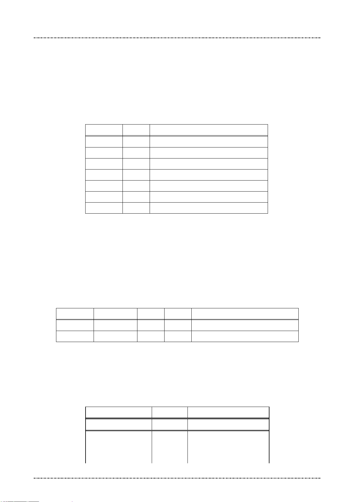
PIN Pad 791 Programmer’s Manual (PCI POS-A) UDN PM0103-U Rev. 06
Section 6 – Contact EMV Level 2 transaction messages 2015-04-20
Message T07 Data Format Table Setup
Format: <STX>T07[Clear]<SUB>[DO]<ETX>[LRC]
Message length: Variable.
Usage: PIN pad will check the consistent of TLV object from terminal via message T01 and
T05. Terminal can add more TLV format checking rules into PIN pad. PIN pad will send
the message T08 (Data Format Setup Response) to host.
Message element:
Field Length
<STX> 1 <02>
T07 3 Message ID
Clear 1 ‘1’: Clear existed Data Format file
<SUB> 1 <1A, Optional, only if [DO] is existed
DO Var. Data Object, format as below
<ETX> 1 <03>
[LRC] 1 Checksum
Format of Data Objects:
The Data Objects for T07 shall include five data fields delimited by <FS>: [Tag#] <FS> [Format]
[Min Len] [Max Len] [Flag], Each data object is delimited by a <SUB> to construct multiple <DO>. If [flag]
is ‘0’, the data object will accept the length of value within [Min Len] and [Max Len]; if [flag] is ‘1’, the
data object will only accept ether [Min Len] or [Max Len] as valid length.
Example: (setup new data format.)
Value and description
<STX>T070<SUB>5F88<FS>4021A0<SUB>5F99<FS>2080B1<ETX>[LRC]
In this example, PIN pad will check if the length of data with tag value 5F99 is 8-byte or 11-byte. PIN
pad will check if the length of data with tag value 5F88 is more than 1-byte and less than 27-byte.
Message flow:
Page81
Uniform Industrial Corp. Proprietary and Confidential Total 342 pages
Tag Data Format Min Len Max Len
5F88 4 02 1A 0 (data length is 2 ~ 26 bytes)
5F99 2 08 0B 1 (data length is 8 bytes or 11 bytes)
HOST Direction PIN pad
1st Message T07
<ACK> (Good LRC)
<NAK> (Bad LRC)
<EOT> (after 3 NAKs)
Or Flag

PIN Pad 791 Programmer’s Manual (PCI POS-A) UDN PM0103-U Rev. 06
Section 6 – Contact EMV Level 2 transaction messages 2015-04-20
<ACK> (Good LRC)
<NAK> (Bad LRC)
<EOT> (after 3 NAKs)
1st Message T08
Page82
Uniform Industrial Corp. Proprietary and Confidential Total 342 pages

PIN Pad 791 Programmer’s Manual (PCI POS-A) UDN PM0103-U Rev. 06
Section 6 – Contact EMV Level 2 transaction messages 2015-04-20
Message T08 Data Format Table Setup Response
Format: <STX>T08[Res][Reason][Err Msg]<ETX>[LRC]
Message length: Variable.
Usage: The response message of command T07.
Message element:
Field Length Value and description
<STX> 1 <02>
T08 3 Message ID
Res 1 ‘0’: Ok,
‘1’: Fail
Reason 1 ‘1’: Fatal Error
‘2’: Format Error
Err Message 8 Optional, if Reason = ‘1’Hex String
<ETX> 1 <03>
[LRC] 1 Checksum
Message flow: Please refer to message T07.
Page83
Uniform Industrial Corp. Proprietary and Confidential Total 342 pages

PIN Pad 791 Programmer’s Manual (PCI POS-A) UDN PM0103-U Rev. 06
Section 6 – Contact EMV Level 2 transaction messages 2015-04-20
Message T09 EMV Config Data Query Message
Format: <STX>T09[Config Type]<ETX>[LRC]
Message length: Fixed 7 bytes.
Usage: Get the group ID of EMV application data or CA public key stored in PIN pad.
Message element:
Field Length Value and description
<STX> 1 <02>
T09 3 Message ID
[Config Type] 1 1: All the IDs of CA public key.
2: All the IDs of EMV application data.
<ETX> 1 <03>
[LRC] 1 Checksum
Message flow:
HOST Direction PIN pad
Message T09
<ACK>/
<NAK>/
<EOT>
<ACK> (Good LRC)
<NAK> (Bad LRC)
<EOT> (after 3 NAKs)
Message T0A
Page84
Uniform Industrial Corp. Proprietary and Confidential Total 342 pages
PIN Pad 791 Programmer’s Manual (PCI POS-A) UDN PM0103-U Rev. 06
Section 6 – Contact EMV Level 2 transaction messages 2015-04-20
Message T0A Response of EMV Config Data Query Message
Format: <STX>T0A[Config Type][Status]<SUB>[ID List]<ETX>[LRC]
Message length: Variable.
Usage: Get the group ID of EMV application data or CA public key stored in PIN pad.
Message element:
Field Length Value and description
<STX> 1 <02>
T0A 3 Message ID
Config Type 1 Return the inputted data in the field [Config Type] of T09.
Status 1 0: There is data in identified data type.
1: No data in identified data type.
2: Arrange exceed.
<SUB> 1 <1A>, Optional if Status is 0
ID List Var Optional, if Status is 0.
[LRC] 1 Checksum
[ID List]: The concatenation of IDs. There is a <FS> between each ID.
Ex. [ID List] = A00000000390<FS> A000000004F8<FS> A000000004F5 ( Config Type = 1 )
[ID List] = A0000000041010<FS>B0123456781234<FS> A000000010 ( Config Type = 2 )
Message flow: Please refer to message T09.
Page85
Uniform Industrial Corp. Proprietary and Confidential Total 342 pages
PIN Pad 791 Programmer’s Manual (PCI POS-A) UDN PM0103-U Rev. 06
Section 6 – Contact EMV Level 2 transaction messages 2015-04-20
Message T0B Delete EMV Configuration Data Message.
Format: <STX>T0B[Config Type]<SUB>[ID List]<ETX>[LRC]
Message length: Variable.
Usage: Host can use this command to delete EMV application configuration data or CA
public key in PIN pad, this command can be sent many times.
Message element:
Field Length
<STX> 1 <02>
T0B 3 Message ID
Config Type
<SUB> 1 <1A>
ID List Var List of ID that will be erased.
<ETX> 1 <03>
[LRC] 1 Checksum
[ID List]: The concatenation of IDs. There is a <FS> between each ID.
Ex. [ID List] = A00000000390<FS> A000000004F8<FS> A000000004F5 ( Config Type = 1 )
[ID List] = A0000000041010<FS>B0123456781234<FS> A000000010 ( Config Type = 2 )
Message flow:
HOST Direction PIN pad
1 1: CA public key.
2: EMV application data.
Value and description
Message T0B
<ACK> (Good LRC)
<NAK> (Bad LRC)
<EOT> (after 3 NAKs)
Page86
Uniform Industrial Corp. Proprietary and Confidential Total 342 pages
<ACK> (Good LRC)
<NAK> (Bad LRC)
<EOT> (after 3 NAKs)
Message T0C

PIN Pad 791 Programmer’s Manual (PCI POS-A) UDN PM0103-U Rev. 06
Section 6 – Contact EMV Level 2 transaction messages 2015-04-20
Message T0C Response of Delete EMV Configuration Data Message.
Format: <STX>T0C[Config Type][Status]<SUB>[Del Result]<ETX>[LRC]
Message length: Variable.
Usage: The response message of command T0B.
Message element:
Field Length Value and description
<STX> 1 <02>
T0C 3 Message ID
Config Type 1 1: CA public key.
2: EMV application data.
Status 1 0: Delete OK
1: Fatal Error
2: Format error.
3: No CA public key or EMV application data
existed.
<SUB> 1 <1A>, Optional, if Status is 0.
Del Result var The results of delete operation on indicated ID
<ETX> 1 <03>
[LRC] 1 Checksum
[Del Result]: It’s the concatenation of results for delete operation on indicated ID. There is a <FS>
between each result. If the delete operation is successfully (When PIN pad finds
out the matched one and delete it successfully), the result is 0. If there is no such ID as
terminal specified, the result is 1.
Ex. Terminal issues message T0B to erase EMV application data with ID “A0000000102020”,
“A0000020” and “A0000000103030”. PIN pad now keeps EMV application data with ID
“A0000000103030” only.
The data in [Del Result] field will be “1<FS>1<FS>0”.
Message flow: Please refer to message T0B.
Page87
Uniform Industrial Corp. Proprietary and Confidential Total 342 pages

PIN Pad 791 Programmer’s Manual (PCI POS-A) UDN PM0103-U Rev. 06
Section 6 – Contact EMV Level 2 transaction messages 2015-04-20
Message T11 Application Select
Format: <STX>T11<ETX>[LRC]
Message length: Fixed 6 bytes.
Usage: PIN pad performs an application select on the active smart card. PIN pad will also
prompt user to insert its card if the card has not yet presented. PIN pad will send the
message T12 (Application Selection Response) to host.
Message element:
Field Length Value and description
<STX> 1 <02>
T11 3 Message ID
<ETX> 1 <03>
[LRC] 1 Checksum
Message flow:
HOST Direction PIN pad
Message T11
<ACK> (Good LRC)
<NAK> (Bad LRC)
<EOT> (after 3 NAKs)
<ACK> (Good LRC)
<NAK> (Bad LRC)
<EOT> (after 3 NAKs)
Application Select Response.
Message T12
Page88
Uniform Industrial Corp. Proprietary and Confidential Total 342 pages

PIN Pad 791 Programmer’s Manual (PCI POS-A) UDN PM0103-U Rev. 06
Section 6 – Contact EMV Level 2 transaction messages 2015-04-20
Message T12 Application Select Response
Format: <STX>T12[Status][Reason][Application Name][ErrMessaeg]<ETX>[LRC]
Message length: Variable, depending on the length of returned application name.
Usage: The message contains the name of final selected application on the smart card to be
sent to host. In general, application name conforms to the EMV 4.3 level 2. See these
standards for more information.
Message element:
Field Length Value and description
<STX> 1 <02>
T12 3 Message ID
Status 1 0:OK
[Application Name] 10-32 EMV application is selected successfully.
Format: Hexadecimal string. The content of this filed will not exist if
there is no EMV application can be selected.
<ETX> 1 <03>
[LRC] 1 Checksum
OR
Field Length Value and description
<STX> 1 <02>
T12 3 Message ID
Status 1 1:Fail
Reason 1 1:Fatal Error
2:Command Format Error
3.Transaction Canceled
4.MSR processing.
[Err Message] 8 Optional, if Reason = ‘1’Hex String
<ETX> 1 <03>
[LRC] 1 Checksum
NOTE. According to EMV Level2’s rule, if IC card can not be read, PIN pad will return message “T1214”
to indicate that terminal should apply magnetic stripe card processing. In this situation, terminal
should issue message Q1 to get magnetic stripe data and issue message T1D to tell PIN pad the
data element in magnetic stripe card and message T15 to transmit necessary data (Amount,
transaction type, and so on.) to make PIN pad record enough information for this transaction.
Message flow: Please refer to message T11.
Page89
Uniform Industrial Corp. Proprietary and Confidential Total 342 pages

PIN Pad 791 Programmer’s Manual (PCI POS-A) UDN PM0103-U Rev. 06
Section 6 – Contact EMV Level 2 transaction messages 2015-04-20
Message T13 Application Select Next
Format: <STX>T13<ETX>[LRC]
Message length: Fixed 6 bytes.
Usage: If the selected EMV application is blocked (terminal will know that in message T16),
terminal could issue this message to ask PIN pad to display rest of EMV application for
cardholder selection.
Message element:
Field Length Value and description
<STX> 1 <02>
T13 3 Message ID
<ETX> 1 <03>
[LRC] 1 Checksum
Message flow:
HOST Direction PIN pad
Message T13
<ACK> (Good LRC)
<NAK> (Bad LRC)
<EOT> (after 3 NAKs)
<ACK> (Good LRC)
<NAK> (Bad LRC)
<EOT> (after 3 NAKs)
Application Select Response.
Message T12
Page90
Uniform Industrial Corp. Proprietary and Confidential Total 342 pages

PIN Pad 791 Programmer’s Manual (PCI POS-A) UDN PM0103-U Rev. 06
Section 6 – Contact EMV Level 2 transaction messages 2015-04-20
Message T15 Start Transaction
Format: <STX>T15<SUB>[AmtAuth]<SUB>[AmtOther]<SUB>
[CurExponent][CurCode]<SUB>[TranType]<SUB>[TranInfo]<SUB>
[Account Type]<SUB>[Force Online]<SUB>[Encrypted Session key]
<ETX>[LRC]
Message length: Variable.
Usage: PIN pad performs an completed EMV transaction flow (via ‘Initiate Application’ through
‘Completion’, see EMV 4.3, book 3, chap 8.2, figure 6 - transaction flow example)
based on the selected EMV application that has corrected application name on the
T12 (Application Select response), PIN pad will also prompt user to do the
appropriated entry when presented, like confirm or enter PIN code. PIN pad will send
the message T16 (Start Transaction Response) to host. If the IC card can not be read
(switch to magnetic stripe card processing), PIN pad will store the information provided
from this message and return the track data of magnetic stripe card and then finish
EMV transaction (The rest of operation on magnetic stripe card is outside scope of
EMV). Terminal could have extra operation on magnetic stripe card transaction (Issue
message 70 for PIN, and so on.).
Message element:
Field Length Value and description
<STX> 1 <02>
T15 3 Message ID
<SUB> 1 <1A>
[AmtAuth]
<SUB> 1 <1A>
[AmtOther]
<SUB> 1 <1A>
[CurExponent] 1 Hexadecimal, tag ‘0x5F36’
[CurCode]
12 Hexadecimal, Amount Authorized tag
‘0x9F02’
12 Hexadecimal, Amount Other, tag
‘0x9F03’
3 Hexadecimal, tag ‘0x5F2A’.
For example, USD$ = 0x840
<SUB> 1 <1A>
[TranType]
<SUB> 1 <1A>
[TranInfo]
<SUB> 1 <1A>
[Account Type]
Page91
Uniform Industrial Corp. Proprietary and Confidential Total 342 pages
2 Hexadecimal, Transaction Type, tag
‘0x9c’
2 Transaction Info, tag ‘0x60000001’
2 Account Type, tag ‘0x5F57’

PIN Pad 791 Programmer’s Manual (PCI POS-A) UDN PM0103-U Rev. 06
Section 6 – Contact EMV Level 2 transaction messages 2015-04-20
<SUB> 1 <1A>
Message flow:
[Force Online]
1 1: Force Online
<SUB> 1 <1A>
[Encrypted
Session key]
16 or
32
(Optional, if the transaction needs user
to enter password for online authorized
and not session key exists, PIN pad
will ignore the password input and
indicate that no password is entered)
DES session key / TDES session key
used for EMV online PIN entry.
<ETX> 1 <03>
[LRC] 1 Checksum
HOST Direction PIN pad
Message T15
<ACK> (Good LRC)
<NAK> (Bad LRC)
<EOT> (after 3 NAKs)
Start Transaction Response.
Message T16
<ACK> (Good LRC)
<NAK> (Bad LRC)
<EOT> (after 3 NAKs)
Page92
Uniform Industrial Corp. Proprietary and Confidential Total 342 pages

PIN Pad 791 Programmer’s Manual (PCI POS-A) UDN PM0103-U Rev. 06
Section 6 – Contact EMV Level 2 transaction messages 2015-04-20
Message T16 Start Transaction Response
Format: <STX>T16[Status][Reason][Err Message][Result]<SUB>
<Advice Need><Reversal Need><Financial Need><ETX>[LRC]
Message length: Variable.
Usage: The message contains the transaction result on the smart card to be sent to terminal.
Message element:
Field Leng
th
<STX> 1 <02>
T16 3 Message ID
Status 1 0:OK; 1:Fail
Reason 1 Optional. (If Status = 1)
Err Message 8 Optional, if Reason = ‘1’Hex String
Result 2 Optional. (If Status = 0)
Value and description
1:Fatal Error
2:Command Format Error
‘Y1’: Offline Approved,
‘Z1’: Offline Declined
‘Y3’: Unable to go online,
Offline Approved
‘Z3’: Unable to go online, Offline Decline.
‘Y4’: Online Approved
‘Z4’: Online Decline
‘A1’: Online Authorize Request,
‘A4’: Application reselection.
<Reversal Need> 1 0: Terminal does not need to send a reversal to
host for this transaction
1: Terminal should send a reversal to host for this
transaction.
<ETX> 1 <03>
[LRC] 1 Checksum
Note: If the [Result] is ‘A1’, then terminal should send online authorization request to issuer host; and
after done, send message T17 to PIN pad to continue transaction. (See EMV 4.3, book 3, chap 9,
figure 7)
Note: If the transaction is switched to MSR processing, T16 will always return “A1” in [Result] field.
Note: If the previous selected application on IC card can’t do the transaction (for example, this
Page93
Uniform Industrial Corp. Proprietary and Confidential Total 342 pages

PIN Pad 791 Programmer’s Manual (PCI POS-A) UDN PM0103-U Rev. 06
Section 6 – Contact EMV Level 2 transaction messages 2015-04-20
application has blocked) but has another application ID within this IC card, PIN pad will response
‘A4’ to let terminal know and terminal can issue message T13 to select another application ID and
issue message T15 to re-start the transaction. Please refer the paragraph of “Ref. 5 Packet
command flow for first EMV application is blocked” in the section of “Overall EMV Level 2
transaction flow reference”.
Message flow: Please refer to message T15.
Page94
Uniform Industrial Corp. Proprietary and Confidential Total 342 pages
PIN Pad 791 Programmer’s Manual (PCI POS-A) UDN PM0103-U Rev. 06
Section 6 – Contact EMV Level 2 transaction messages 2015-04-20
Message T17 Send Online Authorized Code
Format: <STX>T17[OnlineRes]<SUB>[ARC]<SUB>[IAD]<ETX>[LRC]
Message length: Fixed 7 or 16 bytes.
Usage: PIN pad continues to perform the EMV transaction flow after received this online
response from host when the transaction response T16 is ‘A1’ (online authorized
request, see EMV 4.3, book 3, chap 8.2, figure 6 – transaction flow example). PIN pad
will send the message T16 (Start Transaction Response) to host.
Message element:
Field Length Value and description
<STX> 1 <02>
T17 3 Message ID
Online Res 1 ‘0’: Unable to go online
<ETX> 1 <03>
[LRC] 1 Checksum
OR
Field Length Value and description
<STX> 1 <02>
T17 3 Message ID
Online Res 1 ‘1’: Get Online Response,
<SUB> 1 <1A>
ARC 2 Optional, if there is ARC from host.
Authorisation Response code, ASCII
(0~9, A~Z),.
<SUB> 1 <1A>
[IAD]
<ETX> 1 <03>
[LRC] 1 Checksum
OR (If the transaction is changed to Magnetic stripe card processing)
16~32 Optional, if there is IAD from host.
Issuer Authentication Data , Hex string.
Field Length Value and description
<STX> 1 <02>
T17 3 Message ID
Online Res 1 ‘3’: MSR Online Approve
other: MSR Online Decline,
<ETX> 1 <03>
[LRC] 1 Checksum
Page95
Uniform Industrial Corp. Proprietary and Confidential Total 342 pages

PIN Pad 791 Programmer’s Manual (PCI POS-A) UDN PM0103-U Rev. 06
Section 6 – Contact EMV Level 2 transaction messages 2015-04-20
Note: If [Online Res] is ‘4’, then PIN pad will decide to approve or decline by the rule of TAC/IAC default.
Message flow:
HOST Direction PIN pad
Message T17
<ACK> (Good LRC)
<NAK> (Bad LRC)
<EOT> (after 3 NAKs)
Start Transaction Response.
Message T16
<ACK> (Good LRC)
<NAK> (Bad LRC)
<EOT> (after 3 NAKs)
Page96
Uniform Industrial Corp. Proprietary and Confidential Total 342 pages

PIN Pad 791 Programmer’s Manual (PCI POS-A) UDN PM0103-U Rev. 06
Including
Script ID,
Section 6 – Contact EMV Level 2 transaction messages 2015-04-20
Message T19 Send Issuer Script Command
Format: <STX>T19[IS]<ETX>[LRC]
Message length: Var.
Usage: PIN pad performs the Issuer script processing as in EMV transaction flow after
received this command from the host those are the response message when doing
online authorization. This command can be send many times if too many script
commands need to be processed, but the last one should be send before T17
command.
Message element:
Message flow:
Field Length Value and description
<STX> 1 <02>
T19 3 Message ID
IS Var. Issuer Script, format as follow. Hex string.
<ETX> 1 <03>
[LRC] 1 Checksum
HOST Direction PIN pad
Message T19
<ACK> (Good LRC)
<NAK> (Bad LRC)
<ACK> (Good LRC)
<NAK> (Bad LRC)
<EOT> (after 3 NAKs)
Message T20
Issuer Script Command Format: (see EMV 4.3, book 3, chap 10.10, Figure 15)
<EOT> (after 3 NAKs)
Issuer Script Format: (see EMV 4.3, book 3, chap 10.10, Figure 14)
T L T L Script ID Commands
‘71’ or
‘72’
tags,
lengths
Page97
Uniform Industrial Corp. Proprietary and Confidential Total 342 pages
‘9F18’ ‘04’ Identifier (4 bytes)
Issuer Script
Command Format
(see below)

PIN Pad 791 Programmer’s Manual (PCI POS-A) UDN PM0103-U Rev. 06
Section 6 – Contact EMV Level 2 transaction messages 2015-04-20
T1 L1 V1 T2 L2 V2 T3 L3 V3 Tx Lx Vx
‘86’ L(V1) Cmd ‘86’ L(V2) Cmd ‘86’ L(V3) Cmd ‘86’ L(Vx) cmd
Page98
Uniform Industrial Corp. Proprietary and Confidential Total 342 pages
PIN Pad 791 Programmer’s Manual (PCI POS-A) UDN PM0103-U Rev. 06
Section 6 – Contact EMV Level 2 transaction messages 2015-04-20
Message T1D Transaction Data loading
Format: <STX>T1D<SUB>[DO]<ETX>[LRC]
Message length: Variable.
Usage: Terminal can use this command to send transaction data to PIN pad, this command
can be sent many times. PIN pad will save those data inside and apply those data
when do the transaction. PIN pad will send the message T1E to terminal.
Message element:
Field Length
<STX> 1 <02>
T1D 3 Message ID
<SUB> 1 <1A, Optional, only if [DO] is existed
DO Var. Data Object, format as below
<ETX> 1 <03>
[LRC] 1 Checksum
Data Object:
Each <DO> shall include three data field: [Tag#] || [Format] || [Value], and each field shall
delimit with a <FS>. Each data object is delimited by a <SUB> to construct multiple <DO>. The
[tag#] defined in EMV 4.3 Book3 Annex A and specific [tag#] defined at Appendix D of this
manual have the pre-defined data format and length range, those [tag#] must follow up the rule,
otherwise the PP791 will reject this data setup. Any customer defined [tag#] number shall use
the command T07 pre-defined the data format and length range before load by this T1D
command.
Value and description
Note. If the data format is ‘2’ (binary), ‘5’(compressed numeric), ‘6’(numeric) or ‘7’(variable data),
Data Format: (Please also refer to EMV 4.3 BOOK3, section 4.3)
Format
1 a - Alphabetic data (a ~z, A~Z)
2 b - unsigned binary numbers or bit combinations
3 an - Alphanumeric data (a ~z, A~Z, 0~9)
4 ans - Alphanumeric Special data (Characters defined in ISO8859)
5 cn - Compressed numeric data (0~9, left justify, pad hexadecimal ‘F’s. Ex. 12 34 56 12 3F FF)
6 n - Numeric data (0~9, right justify, pad leading hexadecimal zeroes. Ex. 00 00 00 01 23 45)
7 var - Variable data (Any bit combination)
Example:
(IC card can not be read, terminal changes to MSR processing and then load these data into PIN pad.)
Service Code: 0211 (Numeric)
Page99
Uniform Industrial Corp. Proprietary and Confidential Total 342 pages
Description
 Loading...