

Page 1
unden
LO
IQL
OUP
m
SUNDOWNER HANO-HElO UH-OSS
HI
wwww
UH-055
HAND-HELD
Page 2

DESCRIPTION
jl, y. Your UNIDEN Model SUNDOWNER UH-055 represents the most advanced Hand-Held
*
’ type radio ever designed for use in the Citizens Band Radio Service. It will operate on any
of the 40 frequencies designated as citizens band channels by the Department of Cornmunlcfitions. Your Model SUNDOWNER UH-055 features a frequency synthesizing circuit
with PHASE LOCK LOOP techniques to assure ultraprecise Frequency control. This radio
has been Type Accepted and Type Certified by the D.O.C.
WARNING
Before transmitting with your transceiver, you must obtain a Department of Com
munications (D.O.C. ) Citizens Radio Licence. Obtain an application form from the
D.O.C. Before completing the form you should read the conditions governing the li
cencing and operation of the C.R.S. (D.O.C. brochureMS250). This brochure also
can be obtained from the D.O.C. After completing the application form, mail it with
the appropriate fee to the Superintendant Regulatory of Licensing in the State or
(I
lerrltory in which the station will be operated.
Channel information
1
This radio has been designed to provide high level performance in the Citizens Band Radio
Service, which is comprised of the following frequency assignments;
—
ChanrMi
1
Channel Frequency
Channel
in MHz
476.425 15
Channel Frequency
in MHz
476.775
Channel
29
Channel Frequency
in MHz
477 125
2 476.450
3 476 475 17
4 476.500
5 476 525 19
6 476.550
7
8 476600 22
9 476.625 23
10
11 476 675 25
12 476.700 26 477 050
13 476.725
14 476.750
476.575 21
476.650 24 477 000
16
18 476 850 32 477 200
20 476900
27
28 477.100
DUPLEX OPERATING FREQUENCIES
476 800
476.825 31 477 175
476 875 33 477 225
476.925 35
476 950 36 477.300
476 975
477.025 39 477.375
477.075
30 477 150
34
37
38 • 477.350
40
477 250
477 275
477,325
477 400
CHANNEL RX TX
CHI
CH2 476.450 "
CH3 476.475 "
CH4
476.425 MHz
476.500 " 477.250
477.175 MHz
477.200
477.225 "
CHANNEL RX TX
CH5
CH6 476.550
CH7
CH8
476 525 MHz
476575 "
476.600 ■’
477.275 MHz
477300 ”
477.325 "
477.350 ”
2-
Page 3
INSTALLATION
ANTENNA
Since the maximum allowable power output of the transmitter is limited by the D.O.C., the
antenna is a very important factor affecting transmission 'distance. It is for this reason that
we strongly recommended that you install only a qaaiity^ntenna in your new citizens band
system. You have just purchased a superi^ transceiver. Don’t diminish its performance
by installing an inferior antenna. *
Only a properly matched antenna system will allow maximum power transfer from the 50ohm transmission line tolfie ^diating element. Your Uniden dealer is qualified to assist
you in the selection'of the prt^>цr antenna to meet your application requirements.
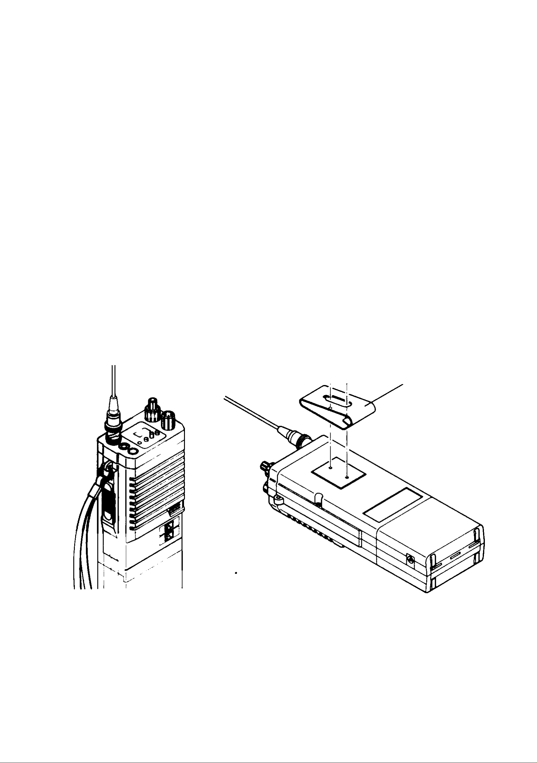
ATTACHMENT QF HANDSTRAP
.A mounting hqle is i>rovided above the PTT switch on the left of the unit. If you wish to use
the handstrap, apply the tip of the metal ring of the strap to this hole and attach by rotating
k. Se&the illustration below.
^ •
ATTACHMENT OF BELT SUSPENDER
If you wish to use a belt suspender, attach it with the 2 screws provided on the rear panel as
illustrated below.
Belt
Suspender
SELCALL
SELCALL (Selective Calling) is a special Squelch System which quiets your receiver until
it receives an Encoded signal from another set which matches the one installed in your set.
This means your set will remain quiet and not receive idle chit chat or other signals until the
station you want to hear calls.
SELCALL is not initially installed in your set (each one has to be individually programmed)
but may be purchased as an option.
-3-
Page 4
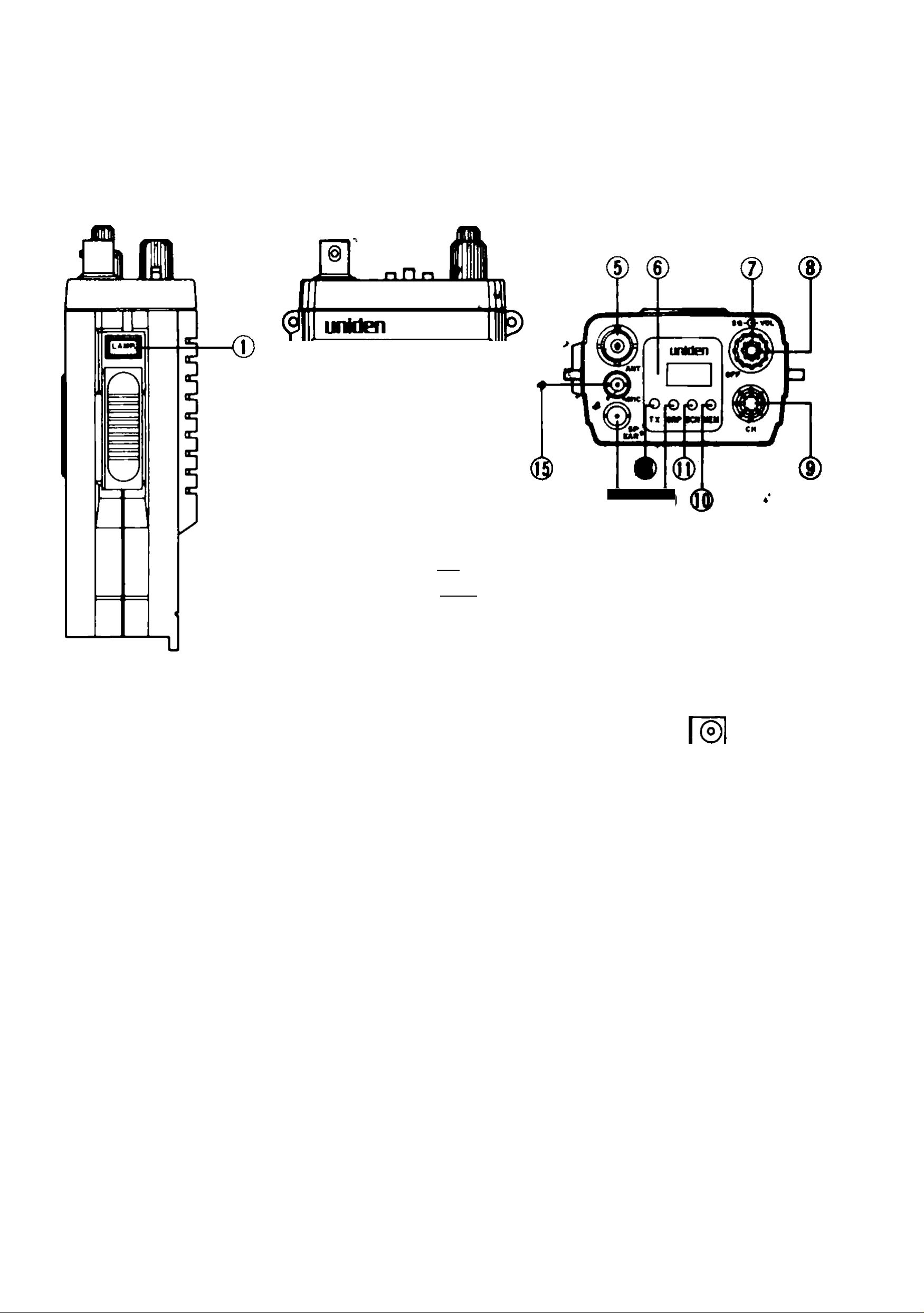
CONTROLS AND THEIR FUNCTIONS
\
to
MOOVOtt huO'NTlo gM-000
wwww
«1
V
<D
llfi^
^ II»"
I
1. CHANNEL LAMP SWITCH: If desired to know proper channel No. in the night opera
tion. turn on this switch, the channel light will light and be able to read it out clearly.
2. PRESS-TO-TALK SWITCH: This will changeover the mode to either transmit or re
ceive. Depress it to fall in the transmit mode, and release to return to the receive mode.
3. POWER HI-LOW SWITCH: This selects the RF output power. In High mode, the output
power is 2.5W (rated output) and LOW 350mW.
In LOW mode, power consumption is decreased to enable a long hours of operation.
For a short distance communication, it is suggested to operate on low power.
-4-
Page 5

4. DUPLEX/SIMPLEX SWITCH: Allows the transceiver to operate via a repeater
station when switched to channels 1,2.3,4.5,6,7 or 8. The set receives on these
channels but automatically transmits on channel 31,32,33,34,35,36,37 or 38 re
spectively. When this switch is on the "simplex" position the set receives and trans
mits normally on the same channel (simplex transmission).
5 ANTENNA CONNECTOR: Connect the flexible antenna provided with the UH-055.
Fit the connector tip of the antenna to the connector on the top panel then press and
rotate it clockwise till it stops with a click sound. An external antenna can be used in
the same manner as the flexible antenna.
6. CHANNEL INDICATOR: LCD indicates the channel number in use.
During NORMAL Mode; Displays the channel selected by the CHANNEL SELEC
TOR Switch.
During SCAN Mode; Displays the channel currently being scanned.
7. SQUELCH CONTROL: This Squelch Control is rotated to cut off or eliminate
received background noise in the absence of an incoming signal. For maximum re
ceive sensitivity, it is desired that the control be rotated only to this point where the re
ceive background noise or ambient background noise is eliminated. Turn the control
fully counterclockwise, then slowly rotate clockwise until the receive noise disap
pears. Any signal to be heard must now be slightly stronger than the average re
ceived noise. Further clockwise rotation will increase the threshold level which a
signal must overcome in order to be heard. Only strong signals will be heard at the
maximum clockwise setting.
8. OFF/VOL. CONTROL: Turn clockwise to apply power to the radio and to set the au
dio volume to the desired listening level. Fully counterclockwise to turn the radio
OFF.
9. CHANNEL SELECTOR SWITCH: This switch selects the desired channel for trans
mission and reception. All channels, except channel 11 may be used for Call Chan
nel. Channel 11 has been reserved by the D.O.C. for emergency communications
involving the immediate safety of individuals or immediate protection of property.
Channel 11 also may be used to render assistance to a motorist. This is the D.O.C.
rule and applies to all operators of citizens band radios.
10. MEM SWITCH:
In the NORMAL mode; Press the MEM switch to program or disable channels in the
selected scan memory.
In the GROUP SCAN mode: When scanning, press the MEM switch to HOLD the
channel currently being scanned. Press again to resume scanning.
In the OPEN SCAN mode: When scanning, press the MEM switch to SKIP over a busy
channel you do not wish to listen to.
-5-
Page 6

11, SCAN SWITCH: When this switch is pressed, the UH-055 will scan any channels pro
grammed in the selected Scan mode.
in the GROUP NORMAL mode or the OPEN NORMAL mode, you can select 2 differ
ent scan speed (FAST or SLOW). When this switch is pressed for more than 1 sec
ond, (a BEEP is hear twice) the radio scans FAST.
When it is pressed for less than 1 second, (a BEEP is heard once) the radio scans
SLOW
NOTE: The radio will not Scan if the selected Scan memory has not been pro
grammed.
12, GROUP SWITCH: This switch is used to select the required Scan mode. When this
switch Is pressed and the G is disappeared, the radio is able to scan in the OPEN
SCAN mode.
Press this switch again to scan in the GROUP SCAN mode.
The G should be indicated on the CHANNEL indicator.
13, TX INDICATOR: Light Emitting Diode (LED) indicates red while transmitting. If the
LED does not indicate red when the PTT switch is depressed, this phenomenon indi
cates battery is exhausted. In this case it is recommended to recharge or replace the
battery.
14, SP/EAR JACK: When you attempt to use an external speaker or an earphone, con
nect it to this jack.
When this jack is plugged, the built-in speaker will not work but the external speaker
or the earphone will.
15.
EXTERNAL RWCROPHONE JACK: When you wish to use an external microphone,
connect it to this jack.
Memory Backup
Channels maintained in the UH-055 memory are protected from loss by a built-in capacitor
which protects the memory for up to 12 hours when you disconnect the Battery Pack.
BATTERY SAVE
In the RX mode, UH-055 saves the battery life. (Except in the SCAN FAST mode and the
NORMAL mode with the optional selcall module.)
-6-
Page 7

OPERATING INSTRUCTIONS
NORMAL OPERATION
RECEIVE OPERATING PROCEDURE
1. Connect the antenna.
2. Before initial use, charge the battery pack for approximately 14 hours.
3. Rotate the SQUELCH control fully counterclockwise.
4. Switch the radio on by turning the OFF/VOLUME control clockwise and adjust for a
comfortable volume level, and adjust for a comfortable squelch level.
5. Select the NORMAL mode by pressing the SCAN switch. The S is disappeared.
6. Rotate the CHANNEL SELECTOR switch to select the required channel.
OPERATING PROCEDURE TO TRANSMIT
--------------------------------------
The transceiver Voltage Standing Wave Ratio (V.S.W.R.) measurement must be
performed prior to the use of the transmitter. A V.S.W.R. ratio in excess of 2:1 may
damage the transmitter.
CAUTION------------------------------------------
TRANSMITTING
To transmit, depress the PRESS-TO-TALK switch. Hold the microphone 5-10 cm from
your mouth and slightly to one side so that your voice does not project directly into the mi
crophone (this provides best results). Speak at a normal level. Never raise your voice or
shout into the microphone. Whenever the PTT switch is pressed, the TX indicator will light.
PROGRAMMING SCAN CHANNELS
When the radio is initially powered up. there will not be any channels programmed into the
GROUP SCAN MEMORY.
To program scan channels into the GROUP SCAN MEMORY, use the following proce
dure:
1. Select the NORMAL mode by pressing the SCAN switch. The S is disappeared.
2. Select the GROUP SCAN Mode by pressing the GROUP switch. TheG should be indi
cated on the CHANNEL indicator.
3. Rotate the CHANNEL SELECTOR switch until the channel you wish to scan is display
ed. Note that the ME should NOT be indicated on the CHANNEL indicator, indicating
that this channel is not currently programmed into the GROUP SCAN MEMORY.
4. Press and hold the MEM switch for about 1 second until a BEEP is heard. The ME
should now be indicated on the CHANNEL indicator indicating that the channel is now
programmed into the memory.
5. Continue steps 3 and 4 to program all the channels you wish to scan.
— 7 —
Page 8

REMOVING GROUP SCAN CHANNELS
To DELETE a programmed channel from the GROUP SCAN MEMORY.
1. Rotate the CHANNEL SELECTOR switch until the channel you wish to remove is dis
played. Note that the ME should be Indicated on the CHANNEL indicator, indicating
that this channel is currently programmed in the memory.
2. Press and hold the MEM switch for about 2 seconds until a BEEP is heard twice. The
ME should now be extinguished.
OPEN SCANNING
To commence open scanning, select the OPEN SCAN mode by pressing the GROUP
switch. The G is disappeared. Then press the SCAN switch.
The UH-055 will commence scanning the programmed channels, and will indicate each
channel on the CHANNEL indicator as it Is scanned.
When a busy channel is found, the radio will 'lock' onto it. and will remain there for as long
as the signal is present, and for 3 seconds after the transmission ceases. This allows the
UH-055 to hold the channel during short breaks in the conversation. Once the channel has
remained clear for 3 seconds, the radio will resume scanning.
If you don't wish to listen to a busy channel, you can SKIP over it by pressing the MEM
switch. The receiver will immediately resume scanning.
When you stop scanning, press the SCAN switch again.
NOTE: 1. During OPEN SCAN mode, the CHANNEL SELECTOR switch and PTT
switch is ignored.
2. The scan rate in SCAN FAST mode is 70 msec per channel, i.e. all 40 chan
nels can be scanned in 2.8 seconds.
GROUP SCANNING
NOTE:
1. If the GROUP SCAN MEMORY has not been programmed when the GROUP SCAN
Mode is selected by pressing the GROUP switch and the SCAN switch is pressed, the
UH-055 will ignore the SCAN switch and a BEEP is heard. It will behave as if it had not
been pressed.
2, The PRIORITY channel number can easily be read when required by:
(a) Stop scanning by pressing the SCAN switch.
(b) Pressing the PTT switch. The radio will jump to the PRIORITY channel for 3 sec
onds before resuming the SCAN function.
To commence GROUP SCANNING, select the GROUP SCAN Mode by pressing the
GROUP switch and select the SCAN mode by pressing the SCAN switch.
The UH-055 will now scan the programmed channels, displaying each channel num
ber and the PRIORITY channel number. Because, before it scans each channel, it
quickly "checks” the PRIORITY channel (set by the CHANNEL SELECTOR switch).
-8-
Page 9

RECEIVING A SIGNAL ON A GROUP SCAN CHANNEL
If a signal is received on a programmed scan channel, the radio will ‘lock* onto that channel
provided there is no signai on the PRiORITY channei.
When the receiver is ‘locked’ onto the scan channel, and at the same time, the channel dis
play will flash from the scan channel to the PRIORITY channel. This is because the receiv
er is still ‘listening’ for signals on the PRIORITY channel.
When the scan channel becomes quiet again, the radio will continue to hold the channel for
a further 3 seconds in order to allow for a natural pause in the conversation before resum
ing the Group Scanning mode.
If there is a transmission on the PRIORITY channel while you are listening to a scan chan
nel. the receiver will immediately transfer to the PRIORITY channel and the PRIORITY
channel number will be displayed.
To manually HOLD a scan channel indefinitely, momentarily press the MEM switch. The
radio will cease scanning and will hold the channel, but will continue to DUAL WATCH the
PRIORITY channel. The S go on and off on the CHANNEL indicator.
To RESUME scanning, momentarily press the MEM switch again. The receiver will re
sume scanning.
To transmit on a Group Scan channel, rotate the channel switch to the required channel,
making it the PRIORITY channel. Return the channel selector to the correct PRIORITY
channel when you have completed your conversation.
REMOVING OPEN SCAN CHANNELS
When the radio is initially powered upfrom the box, all 40 channels will be programmed into
the OPEN SCAN MEMORY.
If you do not wish to scan any particular channels (e.g. if one or more channels are continu
ally busy and always causing the scanning function to pause), you may remove these
channels from the scan group using the following sequence.
1. Select the NORMAL mode by pressing the SCAN switch.
The S should not be indicated on the CHANNEL indicator.
2. Select the OPEN SCAN mode by pressing the GROUP switch. The G should NOT be
indicated on the CHANNEL indicator.
3. Rotate the CHANNEL SELECTOR switch until the channel you wish to REMOVE is
displayed on the CHANNEL indicator.
Note that ME is indicated on the CHANNEL indicator, showing you that this channel is
currently included in the scan group.
4. PRESS and HOLD the MEM switch for about 2 seconds until a BEEP is heard twice.
NOTE: that the ME is now extinguished.
-9-
Page 10

The selected channel has now been removed from the scan group and will not be included
when scanning has commenced and the ME will not be indicated on that channel.
Continue steps 3 and 4 to remove any other channels you do not wish to scan,
REINSTALLING CHANNELS INTO THE SCAN GROUP
To reinstall previously deleted channels into the scan group, simply repeat steps 3 and 4.
However, this time note that there will be a BEEP heard when the MEM switch is pressed,
and the ME will be indicated on the CHANNEL indicator, showing the selected channel is
now included in the scan group.
When you have finished, rotate the channel switch and notice that the ME is indicating on
the CHANNEL indicator which channels are programmed and which have been removed.
SERVICING YOUR TRANSCEIVER
The technical information, diagrams and charts will be supplied upon request.
It is the user's responsibility to see that this radio is operating at all times in accordance with
the D.O.C. Citizens Radio Service regulations.
We highly recommend that you consult a qualified radiotelephone technician for the ser
vicing and alignment of this UHF CB radio product.
Please refer to the WARNING information contained in the 1 st page of this Owner’s Manu
al.
(NOTE: When ordering parts, it is essential to specify the correct model number and serial
number of the unit.)
PREVENTIVE MAINTENANCE
At six to twelve month intervals, the following system checks should be made:
Í
1. Check Standing Wave Ratio (SWR).
OPERATOR TROUBLESHOOTING
Should the unit malfunction or not perform properly, the operator should perform the
procedures indicated below;
1. If the transceiver is completely inoperative.
* Check the battery.
2. If trouble is experienced with receiving,
* Check OFF/VOLUME control setting.
* Be sure SQUELCH is adjusted properly, is the radio over-squelched?
‘ Check to see that the radio is switched to an operational mode.
{
3. If trouble is experienced with transmitting.
* Check to see that the antenna is securely connected to the ANTENNA CONNEC
TOR
-10-
Page 11

SPECIFICATIONS
GENERAL
Channels
Frequency Rarrye
Crystal Oscillator
Microphone
Speaker
Jacks & Connectors
Antenna
Channel Channel Selector.
Controls Power Switch & Vol
Indicators
Cabinet Size
40 *
476 425 MHz to
477 400 MHz
• REPEATER USE
(CH I to CH 8. TX
only)
477 175 MHz to
477 350 MHz
2
Press to talk switcti
16 ohm. 0 2W
MIC 2.5^
SP/EAR&OC Pow
er 3.5ii
BNC
ume. Squelch. Channel
Lamp. Power Hi Lo.
Duplex/Simplex. Mem.
Scan. Group Switch
Cfiannel Indicator
(LCD)
TX Indicator (LED)
W 65 mm
H 175 mm (with Bat
tery pack)
D 42 mm
TRANSMITTER SECTION
Frequency Tolerance at 25®C
(5 minutes after switch on)
Carrier Power
(High)
(Low)
Spurious Emission
476.3625MHz to
477.4625MHz
476.3125MHz to
476.3625MHz
477 4625MHz to
477 5125MHz
Oihe»' Frequency
Current Dram
(High)
(Low)
Modulation Frequency
Response. (1 kHz. OdB
reference, at 600 Hz
deviation)
Lower at 500 Hz
Upper at 2.5 kHz
Microphone Sensitivity for 3
kHz Deviation v
Maximum Deviation ^
at 1 kHz
at 6 kHz
; 10 5 kHz
; 2 5W
: 0.35W
. 200/iW
: 2.5i«W
. 2 5/iW
. 1 Ou^
: 1.3dA
650inA
-6dB
18 dB
5m V
1 4 75 kHz
11 5 kHz
MAX
Weight
Accessories
0 3 kg (without Battery
pack)
r
f
Flexible Antenna. N1CAD Battery Pack. AC
Charger. Earphone.
Handslrap, Belt Clip.
MEASUREMENT CONDITIONS
Power Source lOV
Antenna Impedance
Test Temperature 25“C
Modulation Frequency
Mean Signal Input
Level
Reference Audio
Output Power
Reference Modulation
Deviation
Audio Output Load
•
50 ohm
1 kHz(RX7IX)
1000 yiV
125mW
± 3 kHz Deviation
8 ohms resistive
RECEIVER SECTION
Sensitivity for 12 dB SINAD
Overall Audio Fidelity
(1 kHz. 0 dB reference)
l.ower at 500 Hz
Upper at 2.5 kHz
Adjacent Channel
Selectivity (125 kHz)
Maximum Audio Output Power;
Audio Output Power at 10%
THD
Hum & Noise Ratio at
Input ImV
Squelch Sensitivity at
Threshold
Squelch Sensitivity at Tight
Image Rejection Ratio
IF Rejection Ratio
Oscillator Dropout
•
Voltage
Current Drain at squelched
0 3i^V *
+3 08
-8 dB
60 J8
035W
0.3W
40 iJB
0.2yxV
1 yrV
50 OB
70 OB
7V
55mA
- 11
Current Drain at
Maximum Output
150mA
Page 12

WARRANTY
WARRANTOR: UNIDEN Australia Pty. Lid. (“UNIDEN ”).
ELEMENTS OF WARRANTY: UNIDEN warrants to the original retail owner for the duration of
this warranty, UNIDEN CB Product (hereinafter referred to as the Product) to be free from de
fects in materials and craftsmanship with only the limitations or exclusions set out below.
WARRANTY DURATION: This warranty to the original user shall terminate and be of no fur
ther effect One (1) Year after the date of original retail sale. The warranty is invalid if the Pro
duct is (A) damaged or not maintained as reasonable or necessary, (B) modified, altered, or
used as part of any conversion kits, subassemblies, or any configurations not sold by UNIDEN.
(C) improperly installed, (D) repaired by someone other than an authorized service center for a
defect or malfunction covered by this warranty, (E) used in any conjunction with equipment or
parts or as part of any system not manufactured by UNIDEN (F) installed, programmed or ser
viced by anyone other than an authorized UNIDEN service center.
STATEMENT OF REMEDY: In the event that the product does not conform to this warranty at
any time while this warranty is in effect, warrantor will repair the defect and return it to you with
out charge for parts, service, or any other cost incurred by warrantor or its representatives in
connection with the performance of this warranty. THIS WARRANTY DOES NOT COVER OR
PROVIDE FOR THE REIMBURSEMENT OR PAYMENT OFINCIDENTAL OR CONSEQUEN
TIAL DAMAGES. Some states do not allow this exclusion or limitation of incidental or conse
quential damages so the above limitation or exclusion may not apply to you.
PROCEDURE FOR OBTAINING PERFORMANCE OF WARRANTY: In the event that the
Product does not conform to this warranty, the Product should be shipped or delivered, freight
prepaid, to warrantor at 345 Princes Highway, Rockdale, N.S.W. 2216 with evidence of origin
al purchase.
LEGAL REMEDIES: This warranty gives you specific legal rights, and you may also have
other rights which vary from state to state.
Brisbane:
1/49 Allgas St.
Slacks Creek. OLD. 4127.
Ph (07) 290 1188
Fax (07) 808 4251
Perth:
39 Delawney St.
Balcatta. WA. 6021.
uniden
Australia Pty. Ltd.
HEAD OFFICE:
345 Princes Highway. Rockdale, N.S.W. 2216.
Phone (02) 599 3355 Fax (02) 599 4018
Metboume:
Suite 4/2 Irene St.
Preston. VIC. 3072.
Ph (03) 480 5700
Fax (03) 484 6057
Service Center:
25 Phillips Rd.
Kogarah. NSW. 2217
Adelaide:
19 Nelson St.
Stepney, SA. 5069.
Ph (08) 363 2272
Fax (08) 363 2551
New ZealarKi:
4/166 Harris Rd.
East Tamaki, Auckland
Ph (09) 344 3937
Fax (09) 349 8165
UTUA01852ZZ (SK)
Ph (02) 588 5522
Fax (02) 588 5704
© Copyright 1991 Uniden Australia Pty. Ltd, Printed In the PhUIppInee
Ph (09) 274 4179
Fax (09) 274 0009
 Loading...