

Uniden SUNDOWNER UH-011 Owner's Manual
uni ~n@
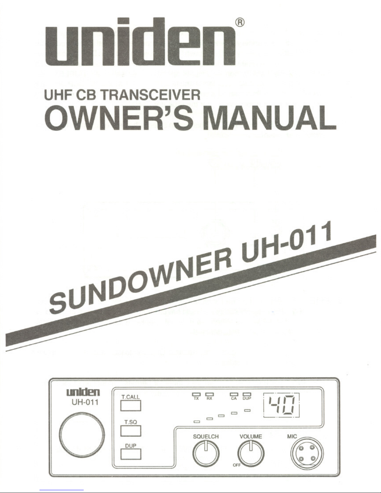
UHF CB TRANSCEIVER
OWNER'S MANUAL
FlLJI-I-O11
IBIIdm
11
T.CALL
UH-O11 Cl
"
n
o
110
\... ~ 11 0
I::J I::J I::J I::J .- .- .--,
TX RX CACUP I ,_, ,-, !
= = = L-~ L~J
=
=
cs ~o M~
DESCRIPTION
YourUNIDEN Model SUNDOWNER UH-011 represents one of the most advanced Mobile
Station type radio ever designed for use in the Citizens Band Radio Service. It will operate
on any ofthe 40 frequencies designated as citizens band channels by the Department of
Communications. Your Model SUNDOWNER UH-011 features a frequency synthesizing
circuit with PHASE LOCK LOOP techniques to assure ultraprecise Frequency control.
This radio has been Type Accepted and Type Certified by the D.O.C.
WARNING
Before transmitting with your transceiver, you must obtain a Department of Com-
munications (D.O.C.) Citizens Radio Licence. Obtain an application form from the
D.O.C. Before completing the form you should read the conditions governing the li-
censing and operation of the C.R.S. A brochure can be obtained from the D.O.C.
After completing the application form, mail itwith the appropriate fee to the Super-
intendant Regulatory of Licensing in the State or territory in which the station will be
operated.
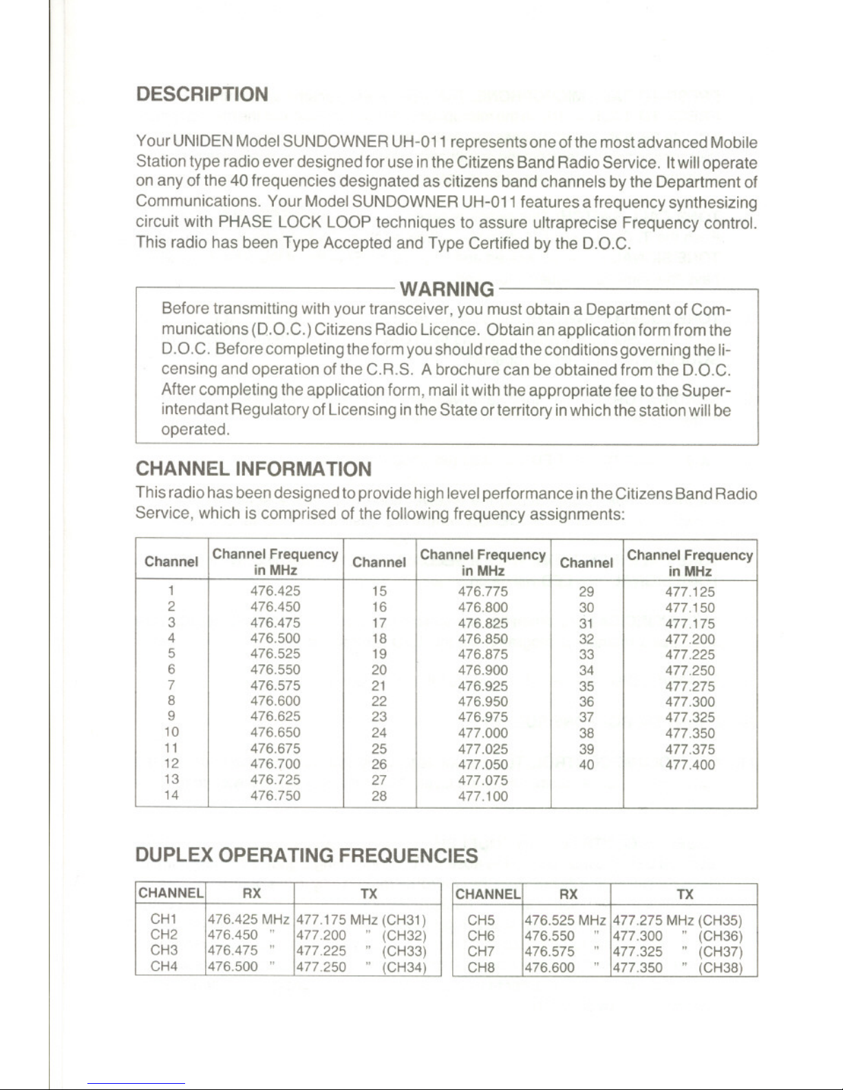
CHANNEL INFORMATION
This radio has been designed to provide high level performance in the Citizens Band Radio
Service, which is comprised of the following frequency assignments:
DUPLEX OPERATING FREQUENCIES
Channel
Channel Frequency
Channel
Channel Frequency
Channel
Channel Frequency
inMHz
inMHz
inMHz
1
476.425
15
476.775 29
477.125
2 476.450 16
476.800 30
477.150
3 476.475 17
476.825 31
477.175
4
476.500
18 476.850
32
477.200
5 476.525
19
476.875 33 477.225
6
476.550 20 476.900 34
477.250
7
476.575
21 476.925
35 477.275
8
476.600
22 476.950 36
477.300
9 476.625
23 476.975
37 477.325
10
476.650
24
477.000
38 477.350
11
476.675
25
477.025
39
477.375
12 476.700
26
477.050 40
477.400
13
476.725
27 477.075
14
476.750
28
477.100
CHANNEL
RX
TX
CH1 476.425 MHz
477.175 MHz(CH31)
CH2
476.450" 477.200
"(CH32)
CH3
476.475"
477.225
"(CH33)
CH4
476.500" 477.250
"(CH34)
CHANNEL
RX
TX
CH5 476.525 MHz
477.275 MHz (CH35)
CH6 476.550
"
477.300
"(CH36)
CH7 476.575
"
477.325
"(CH37)
CH8 476.600
"
477.350
"(CH38)
INSTALLATION
MOBILE STATION INSTALLATION
Plan the location of the transceiver and microphone bracket before starting the installa-
tion. Select a location that isconvenient for operation and does not interfere with the driver
or passenger inthe vehicle. The radio should be securely fastened to some solid face, us-
ing the mounting bracket and self-tapping screws which are provided.
MOBILE STATION ANTENNA
Since the maximum allowable power output of the transmitter is limited by the D.O.C., the
antenna is avery important factor affecting transmission distance. Itis for this reason that
we strongly recommend that you install only a quality antenna in your new citizens band
system. You have just purchased a superior transceiver. Don't diminish its performance
by installing an inferior antenna.
Only a properly matched antenna system will allow maximum power transfer from the 50-
ohm transmission line to the radiating element. Your Uniden dealer is qualified to assist
you in the selection of the proper antenna to meet your application requirements.
For automobile installation, the whip antenna may be used with good effect. The most effi-
cient and practical installation is a full quarter wave whip antenna mounted on the rear
deck or fender top midway between the rear window and bumper.
A short "loaded" whip antenna is more convenient to install on your automobile, although
the efficiency is less than a full quarter wave whip antenna.
For marine installation, consult your dealer for information regarding an adequate ground-
ing system and prevention of electrolysis between fittings in the hull and water.
GROUND SYSTEM
Connect the red DC power cord from the transceiver to the positive, or (+), battery terminal
or other convenient point and con nect the black power lead to the chassis or vehicle frame,
or (-) battery terminal.
SELCALL
SELCALL (Selective Calling) is a special Squelch System which quiets your receiver until
it receives an Encoded signal from another set which matches the one installed inyour set.
This means your set will remain quiet and not receive idle chit chat or other signals until the
station you want to hear calls.
SELCALL is not initially installed in your set (each one has to be individually programmed)
but may be purchased as an option.
OPERATING PROCEDURE TO RECEIVE
1. Be sure that the power source, antenna and microphone are connected to the proper
connectors before going to the next steps.
2. Turn the unitON by rotating the OFF/VOLUME Controlclockwise.
3. Setthe CHANNELSELECTORswitch to the desired channel.
4. Setthe OFF/VOLUMEControl to a comfortable listeninglevel.
5. Listen to the background noise from the speaker. Turn the SQUELCH control slowly
clockwise until the noise JUST disappears (no signal should be present). Leave the
control at this setting. The SQUELCH is now properly adjusted. The receiver will re-
main quiet until a signal is actually received. Do not advance the control too far, or
some of the weaker signals will not be heard.
OPERATING PROCEDURE TO TRANSMIT
CAUTION -
The transceiver Voltage Standing Wave Ratio (V.S.W.A.) measurement must be
performed priorto the use of the transmitter. A V.S.W.R. ratio inexcess of 2:1 may
damage the transmitter.
1. Be sure the operator has read and understands D.G.C. Rules and Regulations priorto
operating the transmitter.
2. Select the desired channel.
3. If the channel is clear, depress the PRESS- TO-TALK switch on the microphone and
speak in a normal voice.
PREVENTIVE MAINTENANCE
At six to twelve month intervals, the following system checks should be made:
1. Check Standing Wave Ratio (SWR).
2. Inspect all electrical connections to ensure that they are tight.
3. Inspect antenna coaxial cable for wear or breaks on shielding.
4. Inspect all screws and other mounting hardware for tightness.
 Loading...