

Page 1

unidenT'
PRO 640XL
Professional Mobile CB radio
OWNER'S MANUAL
rir
Page 2

Welcome!
To the world of sophi sticated, m icro processor con trotted CBradiacommunications. YourUniden
PRO 640XL represents the most advanced mobile radio ever designed tor use in the Citizens
Band Radio Sendee. ItwNI operate on any of the 40 AM, 40 USB or 40 LS8 frequencies authorized
by the Department of Transport and Commur^cations (OOTAC). Your PRO 640 XL features a
superheterodyne dreuit with PHASE LOCKED LOOP techniques to assure precise frequency
control. This radio has been type accepted and certified by the DOTAC.
WARNING
Before transmitting with your transmitter, you must obtain a Department of Transport and
Communications Citizens Band Radio (CBRS) License. Obtain a brochure and a CBRS License
Application Form at your nearest DOTAC office. Mail the completed application form and the
appropriate fee to the Superinterrdent Regulatory of Licensing in the State ot Territory in which
the station will be operated.
CONNECTING THE POWER CORDS
With regard to the connection of the power cords, it may he possible or desirable
to connect the red lead (for negative ground systems) or the black lead (for positive
ground systems) to the ignitionswitchaccessory terminal so that the radio is auto
matically turned off when the ignition switch (key) is turned off.
Alternately, the power lead may be connected to an available terminal on the fuse
block or even to a point in the wiring harness. Care must be taken, however, to
guard against a short circuit condition. When in doubt, please contact your vehi
cle dealer for specific information about your vehicle.
Page 3

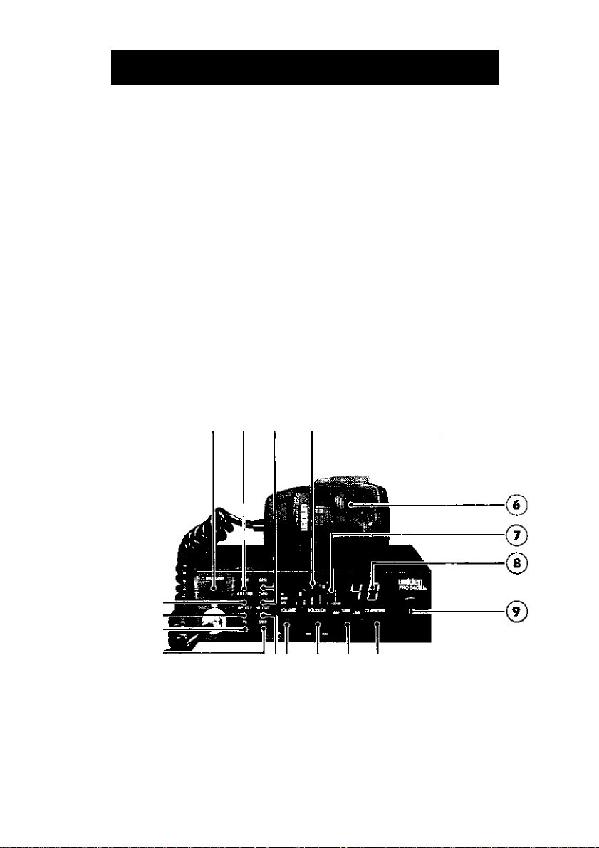
1. MIC GAIN - Adjusts the modulation of the mic for crisp, dear transmission.
2. ANL/NB KEY — You can select Noise Blankerand Automatic Noise Limi
ter orall filters OFF. The ANL/NB helps to reduce harsh background noise caused
by a variety of interference sources.
3. DIM KEY — The dimmer adjusts the front panel lights for optimum viewing.
4. INSTANT CH 9 and 19 — Press these keys to instantly select either channel.
Press again to return to normal 40 channel operation,
5. TXand RX INDICATORS — An LED lights to indicate when the radio is trans
mitting or receiving.
MICROPHONE - TTie operational mode ol the CB is controlled by the push-to-tatk switch on
the mic. Press the switch to activate the transmitter and disable the receiver. Release the switch
to en^le the receiver and disable the transmitter. When transmitting, hold the mic about 2 inches
from your mouth and speak dearly in a normal voice. The mic induded with the PRO 640XL is
a detachsüble, low impedance, dynamic type.
7. S/RF/SWR METER — This LED merer shows the relative strength of the re
ceived signal or the RF output and the Standing Wave Ratio of your antenna,
8. CHANNEL INDICATOR - Displays the channel currently in use.
9. CHANNEL SELECTOR - This switch selects the desired channel tor transmission and
reception. All channels, except channel 9, may be used for communications-between stations
operating under different license. Channel 9 has been reserved by №e DOTAC for emergency
communications involving the immediate safely of individuals or the immediate protection of
property. Channel 9 also may be used to render assistance to a motorist. This is a DOTAC rule
and ap^ies to all operators of CB radios.
10. CLARIFIER — Used to fine tune the receive frequency in USB/LSB modes.
11. RFGAIN — Press this control when strong signa Is are present to improve sig
nal reception sensitivity,
12. SQUELCH - The Squelch control is used to eliminate background noise dur
ing the absence of a transmission. Turn the control fully counterclockwise, then
slowly rotate it back, clockwise until all noise disappears. At this setting any trans
mission must be slightly stronger than the background noise to 'Break Squelch" or
to be heard. Further clockwise rotation will increase the threshold at which a sig
nal will be heard. You can select any level to "Break Squelch"
Page 4
Controls and Functions
13. VOLUME CONTHOL — Rotate clockwise to turn radio on and to increase
volume.
14. SWR KEY — Press to read the Standing Wave Ratio of your antenna. The
SWR LED wtil light when the 5WR key is pressed.
15. HI CUT KEY — Press to reduce the high frequency response of the receiver.
This key can be used to help eliminate the hiss and pop of weak signal reception.
16. PA KEY — Press this switch to the Pub lie Address mode when an external PA
speaker is connected. When the PA mode is selected, the CB radio will be dis
abled. Adjust the PA output level by rotating the mic gain control.
17. AM/USB/LSB Switch — This switch selects the operating mode of either
Amplitude Modulation, Upper Sideband, or Lower Sideband.
® ® 0 ®
(1^
(Q>
@@@@
Pro 640XL Front Panel
Page 5

R1. ANTENNA CONNECTOR — This female connector permits connection of
the transmission line cable male connector (PL-259) to the transceiver.
R2. PUBLICADDRESS —An external 4 ohm 7-watt speaker must be connected
to the "PA SP'jack located on the back of the unit. The speaker must be directed
away from the mic to prevent feedback.
R3. EXTERNAL SPEAKER — The "EXT. SP.'jack is used for remote monitoring.
The external speaker should have a 4 ohm impedance and be rated at least 7
watts. When an external speaker is connected, the internal speaker is disabled.
R4. POWER CONNECTOR - This connector allows you to connect thepoww to the PRO640XL
with the power connecting cable.
Pro 640XL Rear Panel
Page 6

Mobile Installation
Plan the location of the radio and microphone bracket before starting installation.
Select a location that is convenient for operation and does not interfere with the
driver or passenger in the vehicle. The radio should be securely fastened to a solid
surface using the mounting bracket and self-tapping screws which are provided.
MOBILE ANTENNA
Since the maximum allowable power output of the transceiver is limited by the DOT AC. the antenna
is a very important factor affecting transmission distance, ft is for this reason that we strongly
recommend that you install only a quality antenna in your new CB radio system. You have
purchased a superior quality transceiver. Don’t diminish its performance by installing an inferior
antenna.
Only a properly matched antenna system will allow maximum power transfer from the 50-ohm
transmission line to the radiating element. We recommend that you use a SWR meter when
installing your antenna. Set your PRO $40XL to channel 20 and make adjustments to the antenna
until the meter shows SWR = 1. Your local dealer is qualified to assist you in the selection of the
proper antenna to meet your application requirements.
Forautomobile installation, the whip antenna may be used with goodeffect. The most efficient and
practical installation is a full quarter wave whip antenna mounted on the rear deck or fender lop,
midway between the rear window arid bumper.
A short 'loaded" whip antenna is more convenient to install on your automobile, although the
efficiency is less than a full quarter wave whip antenna.
For marine installation, consult your dealer for information regarding an adequate grounding
system and prevention of electrolysis between fittings on the hull and water.
GROUND INFORMATION
Most newer cars and small trucks use a negative ground system, while some older
cars and some newer, larger trucks may use a positive ground system. A negative
ground system is generally identified by
the vehicle motor block, but if you cannot determine the polarity of your vehicle,
consult your vehicle dealer for information.
NOTE; This radio may be installed and used in any 12-voft DC negative
or positive ground system.
thebattery terminal being connected to
NEGATIVE GROUND SYSTEM
If you are operating on a negative ground system, connect the red DC power cord
from the radio to the positive '-I-" battery terminal or other convenient point and
connect the black power lead to the chassis or vehicle frame, or the negative
terminal of the battery.
POSITIVE GROUND SYSTEM
If you are operating on a positive ground system, connect the black DC power
cord from the radio to the nega tivebattery terminal or other convenient point
and connect the red power lead to the chassis or vehicle frame, or the positive"+"
terminal of the battery.
Page 7

Operatinq Procedure
TO RECEIVE
J, Be sure that the power source, antenna and microphone are properly
connected.
2. Turn the unit on by rotating the Volume control clockwise.
3. Set the channel selector switch to the desired channel.
4. Set the Volume control to a comfortable listening level,
5. Listen to the background noise from the speaker. Turn the Squelch control
clockwise until the noise disappears (no signal should be present). Leave the con
trol at this setting. The squelch is now properly set. The receiver will remain quiet
until a signal is actually received. Do not advance the control too far, or some
weaker signals will not be heard.
6. If the transmission you are hearing has annoying high frequency distortion try
activating the Hi Cut feature.
TO TRANSMIT
1, Be sure the operator has read artd understands DOT AC rules and regulations prior to operating
the transmitter.
2, Select the desired channel for transmission.
3, If the channel isclear, depress the push-to-t^k switch on the side of the microphone and speak
CAUTION; The transceiver Voltage Standing Wave Ratio (V,S.W,R.) measure
ment must be performed prior to the use of the transmitter. A “V.S.W.R." ratio in
excess of 2:1 may damage the transmitter. Please check your SWR reading fre
quently by pressing the SWR key.
PREVENTIVE MAINTENANCE
At six to twelve month intervals, the following system checks should be made;
1. Check the Standing Wave Ratio (V.S.W.R.)
2. Inspect all electrical connections
3. Inspect antenna coaxial cable for wear
4. Inspect all screws and other mounting hardware
Page 8

'.;t 11-
-('ÍÚV- 5’,'^ í-
V, > awi-
.- 'Я í~i'-M ¡7*'’ -.
i 'tGMíera ■
Air ,;I'P' ' • '1 "й ■
j brif ’ '
'■ï ЛС .í'r<l:J0Aiir3*4jWE ..j' ■ i.- ■
1. v<í^U i
. ‘C jí >irSyri
r . ■ ■^ . ’rr¡ г /
• Л'Ч'Х, r ■'В «í ' ■
, ;■ T?.l ¿I =
- í' *■ - ait w rr’-'-ir*..: ■■■■ r ■ '
■>г^л ;V*e i-'iíjei TKJÎÏtilJÂiL ?)* 1*. ;.l
■ ■■ <ü ar.i-; tçf -:f-
■> --i ‘ •
. níifti :'íríi .',v ■
* i< T>lírT tcftiï в’"'^ w
ti июу «tóCU, Й j . Ijí - '
is.'tl •'Viv? i»rtf Л1 ,yrt. li - i-V
. *• I >e. ibví!*í- >j bíi atl*' i~ ' ■ ■ '
lí j¿!!* ■чг*’ o# ■-.
tíQi2'v . ji,--: -.- i ' r -
-A '■ -r. ' ■ '
ргйг.т*^ a-? (£'•■ if>íi . . í,
íIí'ItjO ü:-"n^ ■ W- ■■ ;*'”*• ■
. -.re»/ i*:’flçA ■■■тьи!-.''^ ;в-’’. " ' lïl --
ííí' : ' feJ 'Tt-; '■ '■' '•■■■ '■'■
\ ' ■ ,é\ -i:
.yi
■ i‘- i-: 1 t a'" ,■ ■■' .
Page 9

Troubleshooting
If your PRO640XLis not performing up toyourexpectations. please try these simple steps. If you
still cannot get satisfactory results after reading this manual and following the trouble shooting
steps, please call Uniden Australia Pty. Ltd. at (02) 599-3100.
Trouble Check
Unit will not turn on.
No power.
Poor reception
Weak transmission ?. Check antenna system and cable, connec
If you determine that service is necessary contact your local dealer or pack the unit
in its original carton. Send it along with a brief, concise description of the prob
lem, your name, address, phone number, and a copy of the original purchase re
ceipt to the address listed in the warranty.
1. Check power cord and all
connections.
2. Check power cord fuse.
3. Check vehicle electrical system.
1. Check and adjust Squelch
2. Check antenna system and cable, connec
tors.
3. Check operation mode of the radio.
tors.
2. Check antenna grounding,
3. Check for corrosion on connectors.
SERVICING YOUR CB
Technical information, diagrams and charts will be provided upron request. It is the user's
responsibility to see that this radio is operating at all times In accordance with the DOTAC Citizens
Band Radio Service regulations. We highly recommend that you consult a qualified radiotele
phone technician for service and alignment of this radio. When ordering parts, it is important to
specify the correct model number and serial number of this radio.
Please refer to the WARNING information on the first page of this manual.
Page 10

Specifications
Channels:
Frequency Range; 26.965 to 27.405 MHz
Frequency Control:
Frequency Tolerance:
Operating Temp.: -10"C to+50'C
Microphone:
input Voltage:
Current Drain: TX; full mod., 3.0A
Size:
Weight: 3 lb. 2 02.
Antenna Connector:
LED Meter:
TRANSMITTER
Power Output:
Freq. Response;
Output Impedance:
RECEIVER
Sensitivity:
Selectivity:
Image Rejection:
I.F. Frequency:
RF Gain Control:
Automatic Gain:
Noise Blanker:
Squelch:
Audio Output Power:
Freq. Response:
Distortion:
Internal SpeakerExternal Speaker:
PA System;
40 AM, 40 USB, 40 LSB
Phase Locked Loop (PLL] synthesizer
±0.005%
Plug in type: dynamic
13.8 VDC nom. [+ or — ground)
RX: with max audio output, 1.2A
6 7/8" Wx 8 1/4" Dx 2"H
UHF, SO-239
Indicates relative RF output and received sig
nal strength and standing wave ratio.
AM maximunn of 4W
SSB rrtaxinnum of 12W PEP
300 - 2,500 Hz
50 ohms, unbalanced
AM 0.5|iV
SSB O.ISfiy for lOdB [S + N)/N typical
6dB @ 7KHz, 70dB @ 1 OKHz typical
75 dB typical
10.695 MHz
Selectable attenuator for optimum reception
(AGC): less than lOdB change in audio out
put for inputs from 10 to 50,000 microvolts
RF type
Adjustable; threshold less than 1 ¡u\/
1 watts max. into 4 ohms
300 to 3,000 Hz
less than 10% @ 5 watts, @ 1,000Hz
4 ohms, 7 watts round
(not supplied) 4 ohms
7 watts in external 4 ohm speaker
Page 11

'.;t 11-
-('ÍÚV- 5’,'^ í-
V, > awi-
.- 'Я í~i'-M ¡7*'’ -.
i 'tGMíera ■
Air ,;I'P' ' • '1 "й ■
j brif ’ '
'■ï ЛС .í'r<l:J0Aiir3*4jWE ..j' ■ i.- ■
1. v<í^U i
. ‘C jí >irSyri
r . ■ ■^ . ’rr¡ г /
• Л'Ч'Х, r ■'В «í ' ■
, ;■ T?.l ¿I =
- í' *■ - ait w rr’-'-ir*..: ■■■■ r ■ '
■>г^л ;V*e i-'iíjei TKJÎÏtilJÂiL ?)* 1*. ;.l
■ ■■ <ü ar.i-; tçf -:f-
■> --i ‘ •
. níifti :'íríi .',v ■
* i< T>lírT tcftiï в’"'^ w
ti июу «tóCU, Й j . Ijí - '
is.'tl •'Viv? i»rtf Л1 ,yrt. li - i-V
. *• I >e. ibví!*í- >j bíi atl*' i~ ' ■ ■ '
lí j¿!!* ■чг*’ o# ■-.
tíQi2'v . ji,--: -.- i ' r -
-A '■ -r. ' ■ '
ргйг.т*^ a-? (£'•■ if>íi . . í,
íIí'ItjO ü:-"n^ ■ W- ■■ ;*'”*• ■
. -.re»/ i*:’flçA ■■■тьи!-.''^ ;в-’’. " ' lïl --
ííí' : ' feJ 'Tt-; '■ '■' '•■■■ '■'■
\ ' ■ ,é\ -i:
.yi
■ i‘- i-: 1 t a'" ,■ ■■' .
Page 12

WARRANTY
Uniden PRO 640XL CB Radio Australian 2 Year Warranty.
(Accessories are covered for 90 days only).
Note: Rease keep your sales dodret as it provides evidence of warranty.
WARRANTOR: Uniden Australia Pty. Ltd.
ELEMENTS OF WARRANTY; Uniden warrants to the original retail owner for the duration of
this warranty, its PRO 640XL CB Radio (hereinafter referred to as ttie Product), to bo free
from defects in materials ar>d craftsmanship with only the limitatirms or exclusions set out
below.
WARRANTY DURATION: This warranty to the original user only shall terminate and be of
no further effect Two (2) Years after the date of original retail sale. This warranty will be
deemed invdid ifthe product is (A) Damaged or not maintained as reasonable and necessary,
(B) Modified, altered, or used as part of any conversion kits, subassemblies, or any configu
rations not sold by Uniden, (C) improperly installed, (D) Repaired by someone other than an
authorised Uniden Repair Agentforadefector malhinction covered bytfriswarranty,(E) Used
in conjunction with any equipment or parts or as part of a system not manufactured by Uniden,
(F) Installed, programmed or sen/iced by anyone other than an authorised Uniden Repair
Agent, (G) Where the Serial Number label of the product has been removed or damaged
beyond recognition.
PARTS COVERED: This warranty covers tor 2 years; the Transceiver and Microphone only.
All accessories, (Leads, Brackets, Clips, Screws etc), are covered for 90 days only.
STATEMENT OF REMEDY : in the event that the product does not conform to this warranty
at any time while this warranty is in effect, the warrantor will at its (Sscretion, repair the defect
or replace the product and return It to you without charge for parts or service. THIS
WARRANTY DOES NOT COVER OR PROVIDE FOR THE REIMBURSEMENT OR PAY
MENT OF INCIDENTAL OR CONSEQUENTIAL DAMAGES.
WARRANTY CARD: If a warranty card had bean irx:luded with this product then please fill
it in and return it to us within 14 days of purchase. Your name and the sériât number of the
product will than be registered in our database and this will help us to process your claim with
greater speed and efficiency should you require warranty service.
PROCEDURE FOR OBTAINING PERFORMANCE OF WARRANTY. In the event that the
Product does not conform to this warranty, the Product should be sNpped or delivered freight
pre-paid, with evidence of original purchase, (eg/a copy of the sales docket), to the warrantor
at:
UNIDEN AUSTHAUA PTY LTO - SERVICE DIVISION
345 Princes Highway, Rockdale, Sydney. NSW 2216.
Customers in other States should ship or deliver the Product
freight pre-paid to their nearest Uniden Authorised Repiur Centre.
(Contact Uniden for the nearest Warranty Agent to you).
UTUA01651CC e Copyright 1992 Uniden Australia Pty, Ltd. Printed in the Philippines
Ph (02) 599 3100 Fx (02) 599 3278
Adelaide (06) 365 2588 Brisbane (07) 290 1188
Melbourne (03) 335 4322 Perth (09) 227 6386
 Loading...