

Uniden PRO6400N0-4K, PRO800N2-5MP, PRO1600N3-5MP, PRO12800N0-4K, PRO3600N4-4K User Manual
...Page 1

ProSeries NVR
INSTALLATION GUIDE
Pro12800N0-4K
Pro6400N0-4K
Pro3600N4-4K
Pro1600N3-5MP
Pro800N2-5MP
Pro800N2-5MP
Pro1600N2-4K/PRO800N2-4K
© 2018 Uniden America Corporation
Irving, Texas
Issue 1, March 2018
Page 2

© 2018 Uniden America Corporation
CONTENTS
UNIDEN PROSERIES NVR INSTALLATION GUIDE ............. 5
OVERVIEW ............................................ 5
PROSERIES NVR INSTALLATION GUIDE ATTRIBUTES .............5
REQUIREMENTS ....................................... 5
FIRMWARE AND DOCUMENTATION UPDATES ............. 5
DEFAULTS ............................................ 6
FRONT PANEL (PRO12800N0-4K) ........................... 7
Thank you for purchasing this Uniden NVR high-quality video security system. This manual refers
to the following models:
• Pro12800N0-4K
• Pro6400N0-4K
• Pro3600N4-4K
• Pro1600N3-5MP
• Pro800N2-5MP
• Pro800N2-5MP
• Pro1600N2-4K/PRO800N2-4K
Uniden surveillance products are not manufactured and/or sold with the intent to be used for illegal
purposes. Uniden expects consumer’s use of these products to be in compliance with all local,
state and federal law. For further information on video surveillance and audio recording legal
requirements, please consult your local, state and federal ofcial.
Uniden constantly works on improving our products. This includes updating our documentation
with the latest rmware changes. Go to www.uniden.com to nd the latest version of all
documentation.
© 2018 All rights reserved.
REAR PANEL INTERFACES ................................ 8
PRO12800N0-4K ....................................... 8
PRO6400N0-4K ........................................ 9
PRO3600N4-4K ........................................ 9
PRO1600N3-5MP ...................................... 10
PRO800N2-5MP ....................................... 10
PRO1600N2-4K/PRO800N2-4K ........................... 11
INSTALLATION ......................................... 12
INSTALLATION REQUIREMENTS ........................ 12
HARD DISK INSTALLATION ............................. 12
PRO12800N0-4K HARD DISK DRIVE INSTALLATION ...............12
PRO3600N4-4K/PRO3600N8-4K AND PRO6400N0-4K HARD DISK
INSTALLATION ..............................................12
PRO SERIES 8 AND 16 CHANNEL NVR HARD DISK INSTALLATION ..13
CLEAR DISK MISSING ALARM .......................... 13
DISABLE DISK MISSING ALARM ........................ 14
NETWORK CONNECTION SCHEMATIC DIAGRAM ............ 15
INITIAL TURN UP ........................................ 16
RECOMMENDED TURN UP ORDER ...................... 16
LOGIN SYSTEM ....................................... 18
INITIAL SETUP ....................................... 18
SYSTEM SETTING ..................................... 19
TIME SETUP ................................................19
NEW USER/PASSWORD SETUP ...............................19
ProSeries NVR Installation Guide Only 03162018.indd 2-3 3/26/2018 10:32:29 AM
Page 3

RECORDING SCHEDULE SETUP ...............................20
Basic Schedule Setup ......................................21
Motion Detection Only Recording Setup ........................21
UNIDEN PROSERIES NVR INSTALLATION GUIDE
SET UP ALARM INPUTS/OUTPUTS .............................22
Alarm Inputs .............................................22
Alarm Outputs ...........................................23
SET UP EMAIL NOTIFICATION .................................23
SET UP REMOTE DDNS ACCESS ..............................24
CHECK FIRMWARE VERSION; UPDATE IF NEEDED ...............25
HARD DISK DRIVE SETUP .............................. 25
UNCHECK MISSING ALARM FOR ALL UNINSTALLED HDDS ........25
ADDING HDDS/RAID .........................................26
Install the Hard Disk Drives ..................................27
Enabling the RAID (Optional) ................................27
Setting up the RAID if Enabled ...............................27
Formatting the HDDs/RAID ..................................28
CAMERA SETUP ...................................... 28
SET UP IP ADDRESSES - 1 LAN PORT ONLY .....................28
SET UP IP ADDRESSES - 2 LAN PORTS .........................29
SET UP IP CAMERAS ........................................29
PLANNING IP ADDRESSES ................................29
ADDING IP CAMERAS ................................. 29
PREREQUISITES ............................................29
SET UP CHANNEL GROUPS. . . . . . . . . . . . . . . . . . . . . . . . . . . . . . . . . . .30
OVERVIEW
This Installation Guide helps the installer to install and initially congure Uniden's ProSeries series
NVR surveillance systems. It provides basic instructions to install the NVR receiver; it does not
provide detailed instructions on how to use the rmware. For detailed rmware operation, refer to
the online ProSeries NVR User's Manual at www.uniden.com. A series of informational articles can
also be found at https://unidenamerica.desk.com/?b_id=17003.
This Installation Guide uses ProSeries NVR models (version 2.0) with an operating interface of
NVR 64 channels as a generic example for intallation procedures. Details vary according to the
specic model being installed.
PROSERIES NVR INSTALLATION GUIDE ATTRIBUTES
This Guide provides a decription of the various Uniden ProSeries NVR models' hardware. It also
provides a basic installation checklist with accompanying procedures for each step.
The Installation Guide text conrms to the following nomenclature:
• Italic text indicates a screen name, menu selection, etc. It is usually prefaced with "Select."
• BOLD text indicates an action, such as Save, Copy to, etc. It is usually prefaced with "Click."
REQUIREMENTS
• Access to standard AC outlet (AC100~240V, 50Hz~60Hz)
• Phillips-head screwdriver may be required
• HDMI 1080p monitor (for initial boot up)
• External PoE network switch to add more than 8 cameras (ProSeries series 16 ~ 128 channel
NVRs)
• Camera network cables if devices purchased separately (only included in Pro Series kits)
• Optional 12VDC power supply (if PoE not used)
• HDMI or VGA cable (HDMI cable included in Pro Series kits)
• Western Digital Purple or Seagate SkyHawk surveillance hard drives (for systems containing
more than 8 cameras)
Name Channels ...........................................30
Create a Preview Group ....................................31
Assign Channels to the Preview Group .........................31
FIRMWARE AND DOCUMENTATION UPDATES
Because Uniden strives to provide the latest technology and quality in all of its products, rmware
updates may be available with no prior notice. Check for updates at support.uniden.com/pro-
support. Update the rmware manually either locally or remotely through a web browser.
SET UP CAMERA TOURS .....................................31
SET UP PTZ CAMERA(S) .....................................33
Congure PTZ Camera .....................................33
Adjust PTZ Camera ........................................33
Set Up PTZ Presets .......................................33
Set Up PTZ Cruise ........................................34
Set Up PTZ Pattern ........................................34
Set Camera Settings for each Channel .........................35
5
ProSeries NVR Installation Guide Only 03162018.indd 4-5 3/26/2018 10:32:29 AM
Page 4
DEFAULTS
• Administrator user name: admin.
• Administrator password: No password; leave blank.
• LAN1 IPv4 address: DHCP auto enabled
• LAN2 IPV4 address: 192.168.2.189 (if equipped with second network port)
• Default video resolution: 1080p
• Factory-installed hard drives are formatted and ready to record.
• Daylight savings time enabled; however, the start and stop dates must be set.
• Unpopulated hard drive connections will trigger an "unpopulated hard drive" alarm. See page
25 for instructions on how to turn it off.
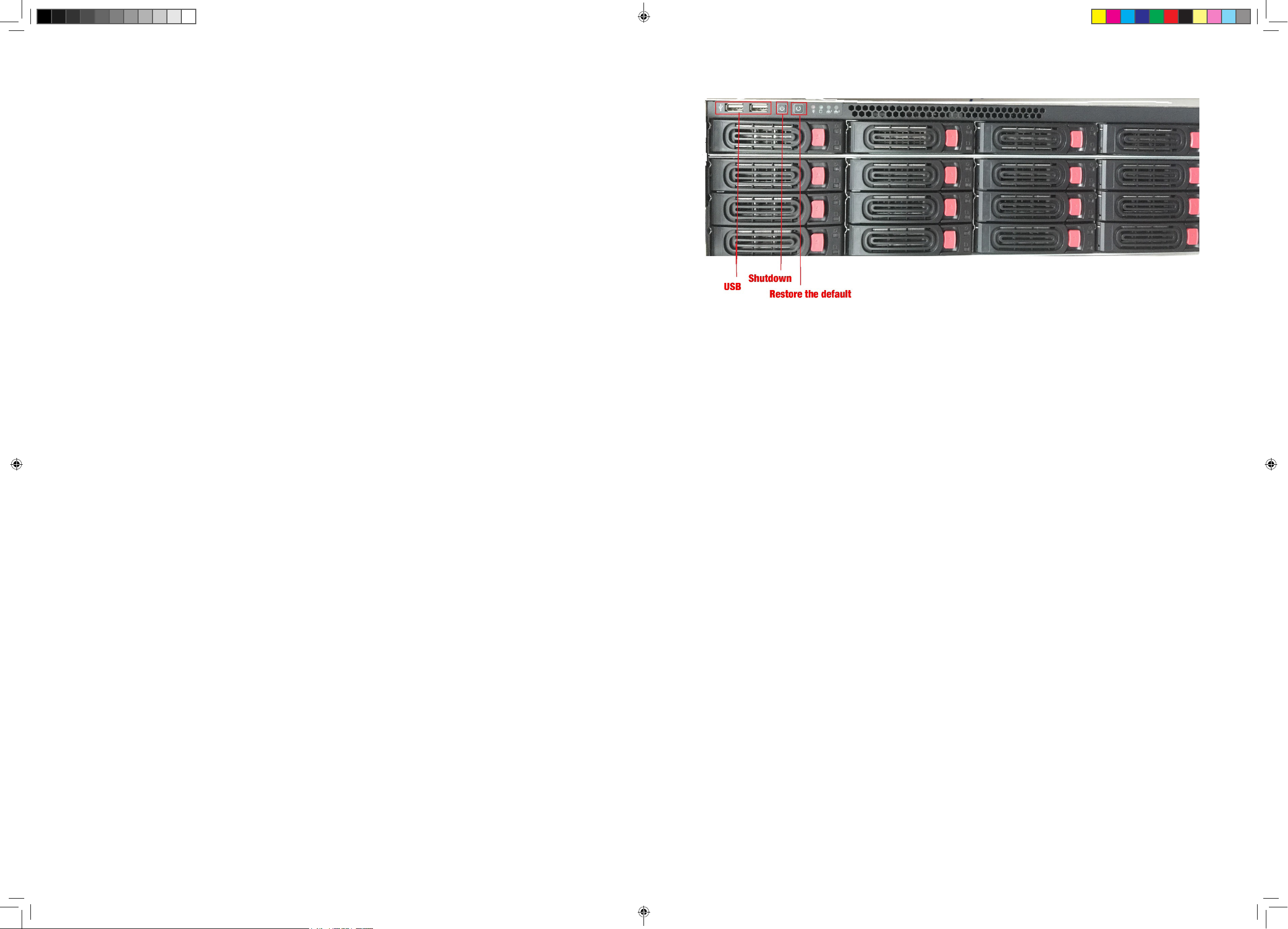
FRONT PANEL (PRO12800N0-4K)
6 7
ProSeries NVR Installation Guide Only 03162018.indd 6-7 3/26/2018 10:32:29 AM
Page 5
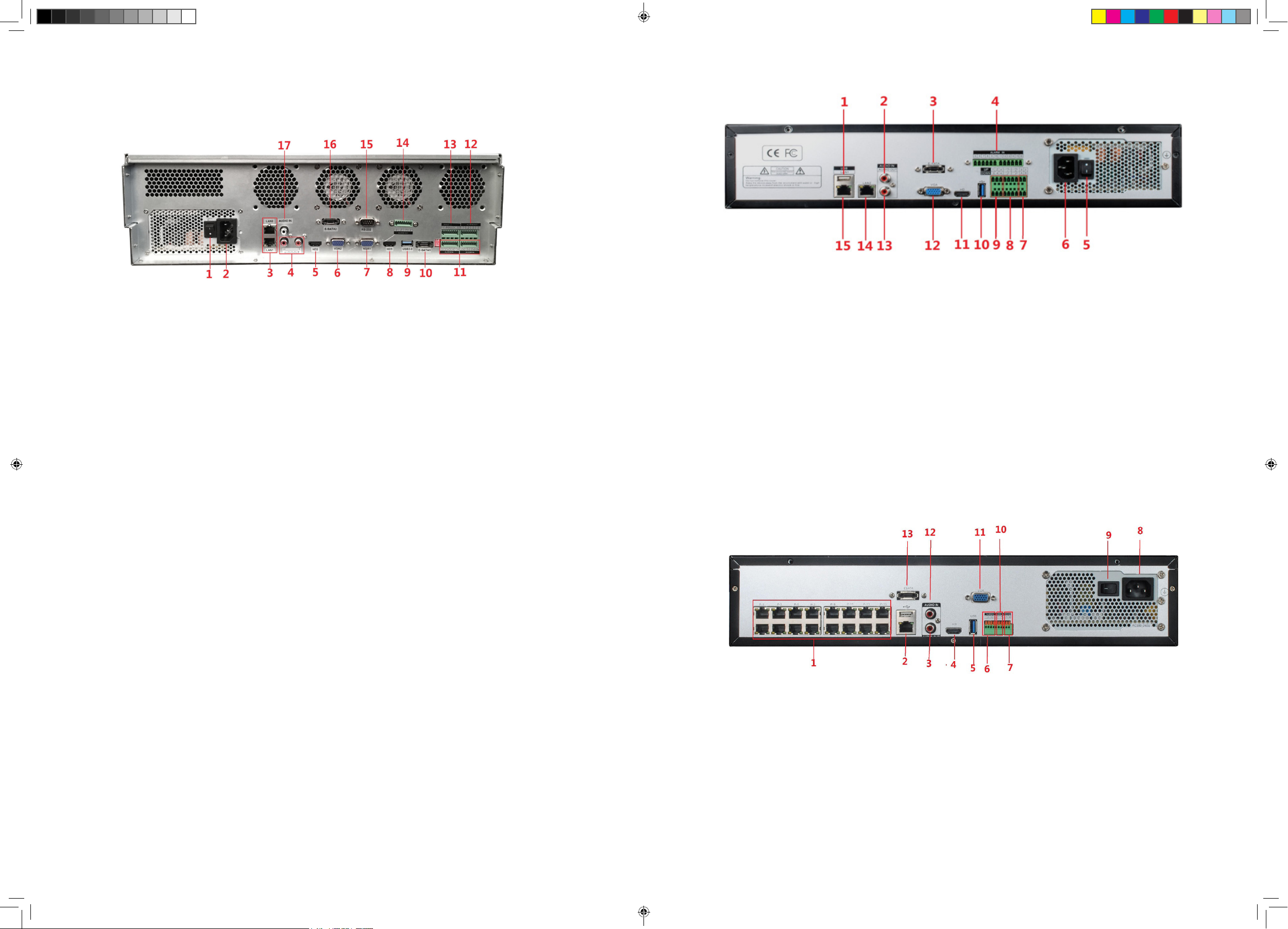
PRO12800N0-4K
REAR PANEL INTERFACES
PRO6400N0-4K
1. Power Switch
2. 110-220VAC Power Supply Plug
3. LAN1/LAN2 Interface
4. Audio Output
5. HDMI Video Output 2
6. VGA Video Output 2
7. VGA Video Output 1
8. HDMI Video Output 1
9. USB 3.0
Cameras connect to LAN1 (PoE gigabit network switch)
10. E-Sata Interface 1
11. Alarm Input
12. Alarm Output (1, 2, 3, 4)
13. RS422 Interface
14. Alarm Output (5, 6, 7, 8)
15. RS232
16. E-Sata Interface 2
17. Audio Input
1. USB 2.0
2. Audio Input
3. E-SATA
4. Alarm Input (5-16)
5. Power Switch
6. 110-220VAC Power Supply Plug
7. RS485
8. Alarm Output
Cameras connect to LAN1 (PoE gigabit network switch)
PRO3600N4-4K
9. Alarm Input (1-4)
10. USB 3.0 Alarm Output
11. HDMI Video Output
12. VGA Video Output
13. Audio Output
14. LAN 1
15. LAN 2
8 9
ProSeries NVR Installation Guide Only 03162018.indd 8-9 3/26/2018 10:32:29 AM
Page 6
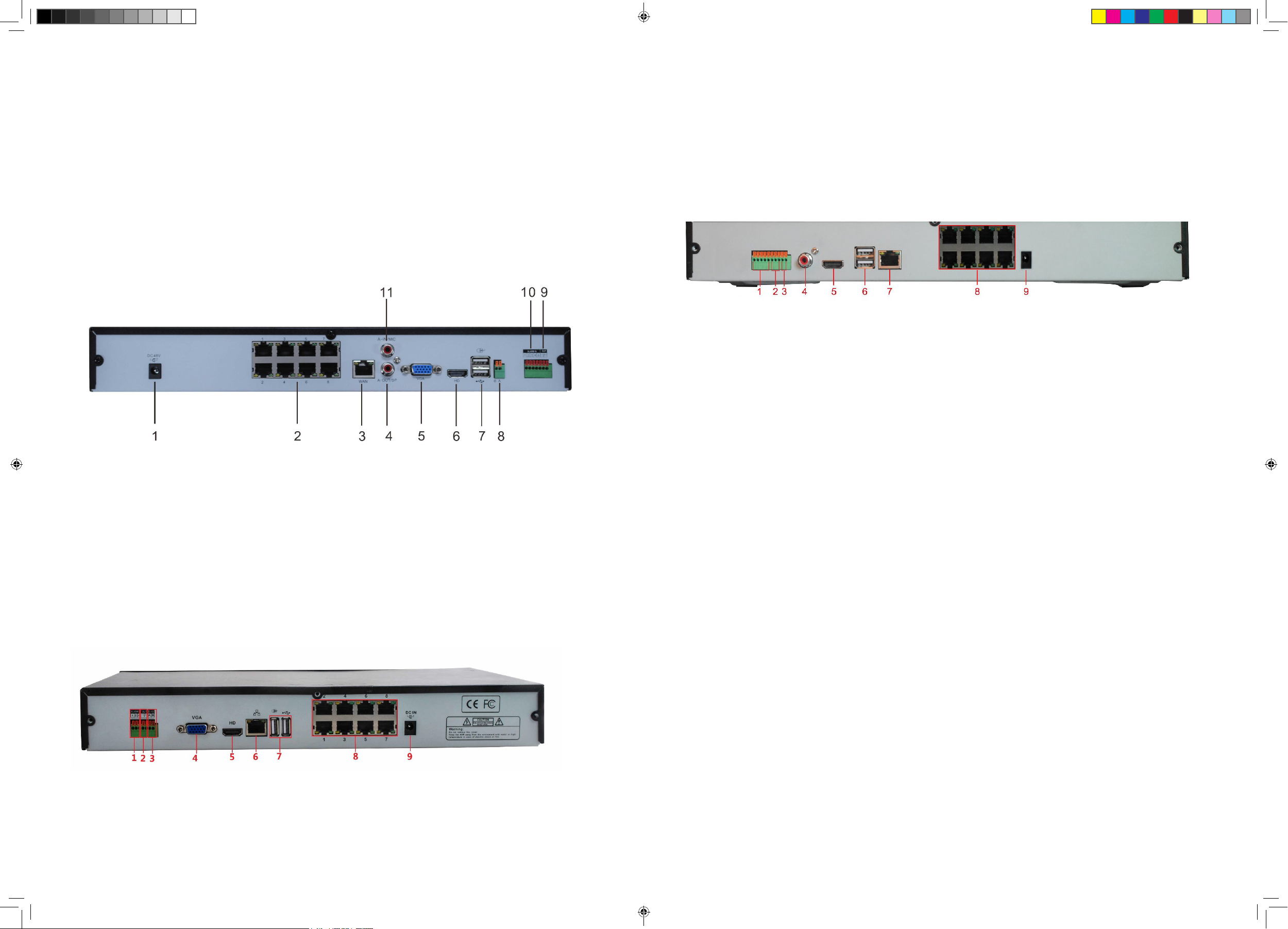
1. PoE Camera Ports
7. Alarm Output
1. Alarm Input
6. RJ45 Network Interface
2. RJ45 Network Interface (LAN1)/
USB2.0
3. Audio Output
4. HDMI Video Output
5. USB 3.0
6. Alarm Input
Cameras connect to LAN1 (PoE gigabit network switch)
PRO1600N3-5MP
8. RS485 Interface
9. Power Switch
10. 110-220VAC Power Supply Plug
11. VGA Video Output
12. Audio Input
13. E-SATA
2. Alarm Output
3. RS485
4. VGA Video Output
5. HDMI Output
PRO1600N2-4K/PRO800N2-4K
1. Alarm Input
2. Alarm Output
3. RS485
4. Audio Output
7. USB 2.0
8. PoE Camera Ports
9. DC48V
6. USB 2.0
7. RJ45 Network Interface
8. PoE Camera Ports
9. DC15V
1. DC48V
2. PoE Camera Ports
3. RJ45 Network Interface
4. Audio Output
5. VGA Vido Output
6. HDMI Video Output
PRO800N2-5MP
5. HDMI Video Output
7. USB 2.0
8. RS485
9. Alarm output
10. Alarm Input
11. Audio Output
10 11
ProSeries NVR Installation Guide Only 03162018.indd 10-11 3/26/2018 10:32:30 AM
Page 7
INSTALLATION
remove the upper bracket.
3. Connect the HDD power lines and data cable.
INSTALLATION REQUIREMENTS
Unplug the device from power before opening the device case.
• Install the device in a horizontal position.
Do not install the device in a vertical or tilted position.
• The device's operating temperature range is 32˚F to 122˚F (0˚C to 50˚C).
Do not locate the device in places with high temperature, humidity, dust, or smoke.
• The device is not water-resistant or waterproof. Do not place objects containing liquid such as a
glass or mug on the device.
• In order to ensure normal heat dissipation, install the device in a well-ventilated area.
• Use Uniden's recommended specic surveillance hard disk drives (Western Digital Purple or
Seagate SkyHawk surveillance hard drives) when adding a hard disk drive.
• Verify that the NVR power supply and AC outlet are reliably grounded.
HARD DISK INSTALLATION
WARNING! IF YOUR SYSTEM HAS LESS THAN 128 CHANNELS, CONFIRM THAT THE
DEVICE IS POWERED OFF AND UNPLUGGED FROM POWER BEFORE INSTALLING ANY
HARD DISK DRIVES.
Install optional 1, 2, 8, or 16 HDDs into the device, depending on specic model requirements.
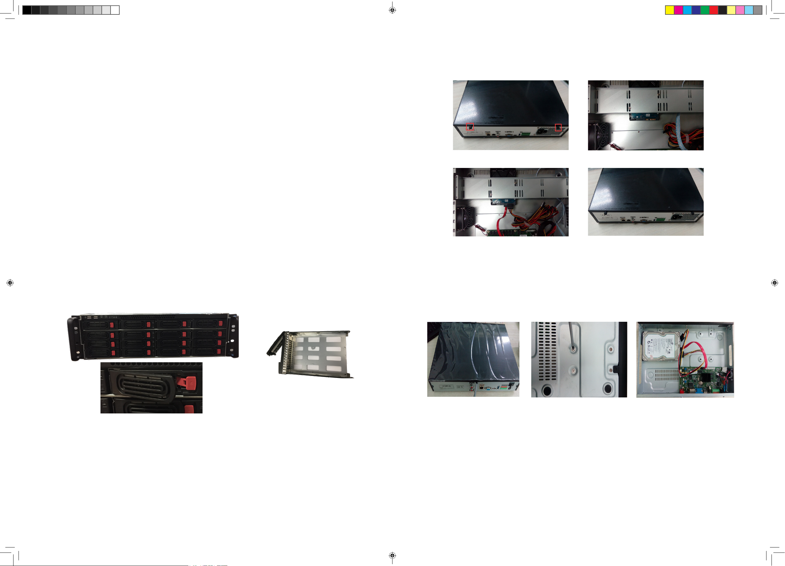
PRO12800N0-4K HARD DISK DRIVE INSTALLATION
This is a hot-swappable model - no need to power down.
1. Press the red release button on an HDD slot and pull out the hard disk tray.
4. Close the cover and fasten it with the screws.
Disassemble the case Fix hard disk
Connect hard disk lines Lock the case
PRO SERIES 8 AND 16 CHANNEL NVR HARD DISK INSTALLATION
1. Unscrew the upper cover screws and open the cover.
2. Fix the hard disk to the metal NVR base with screws.
3. Connect the HDD power lines and data cable.
Release Buttons Hard Disk Drive Tray
2. Remove the hard disk from its box and slot it into the tray. Use screws to attach the hard disk to
the tray.
3. Insert the hard disk tray into the empty HDD slot.
PRO3600N4-4K/PRO3600N8-4K AND PRO6400N0-4K HARD DISK
INSTALLATION
4. Secure the cover again.
Open the cover Install HDD Connect HDD power lines
and data cable
CLEAR DISK MISSING ALARM
Clearing the alarm silences it; however, it does not prevent the alarm from sounding again.The
only way to fully clear the alarm is to correct the condition that caused the alarm in the rst place.
1. From Disk Manager/Storage Management, uncheck any Missing Alarm column boxes.
1. Remove the cover from the NVR by unfastening the screws on the case cover.
2. Fix the HDD to the HDD bracket with screws. If installing the HDD on the under bracket,
12 13
ProSeries NVR Installation Guide Only 03162018.indd 12-13 3/26/2018 10:32:34 AM
Page 8

NETWORK CONNECTION SCHEMATIC DIAGRAM
2. Click Save.
DISABLE DISK MISSING ALARM
Disable this alarm for any HDDs that are not present.
1. Login to the NVR system.
2. Select Disk Manager. The Storage Management side tab screen should display the physical
drives connected to the system.
3. Each installed HDD will have information populated along its row. If a row is not populated with
a HDD, uncheck the box in the Missing alarm column to disable this alarm for this uninstalled
HDD.
Although it is not required, at this point in the installation you may run cables and
install the cameras .
4. Repeat this procedure for every installed HDD.
5. Click Save in the bottom left corner.
14 15
ProSeries NVR Installation Guide Only 03162018.indd 14-15 3/26/2018 10:32:35 AM
Page 9

INITIAL TURN UP
RECOMMENDED TURN UP ORDER
_______ From Channel Setting/Channel Grouping/Tour (right column), set up Tour Groups if
desired (see page 31).
_______ Check and adjust camera images for focus and eld of view in Preview (see page
33).
INITIAL SYSTEM SETUP
In the Guide (see page 18), set:
• Default Language
• Display Resolution (Default - 1920 x 1080)
• LAN1 and LAN2 Network Settings
_______
_______
_______ The recording schedule default is for all cameras to record all the time (Channel
_______ From System Setting/User Management, set up new users and change the Admin
_______ From System Setting/Alarm Management/Alarm Input (or Alarm Output) top tab, set
_______ From System Setting/Network Parameter/Email Setting top tab, set up email
_______ From System Setting/Network Parameters/DDNS Setting top tab select Enable DDNS
_______ From Maintenance/System Information/Device Information top tab, update rmware if
HARD DISK DRIVE (HDD) SETUP
_______ Go to Disk Manager/Storage Management and uncheck Missing Alarm for all non-
_______ From Disk Manager/Storage Management, verify HDD quantity and sizes (see page
_______
When nished, select Next time no longer display and click Finish.
Go to System/Time Setting, Device Time tab (see page 19) and set:
• Device Time
• Date Format
• Time Zone
• Enable Daylight Savings Time and set start and end dates.
• Network Time Protocol (NTP) is enabled by default. Change to internal time source
if desired (see page 19). Turn off if the customer does not want the recorder to go
out on the internet.
Setting/Schedule Setting/Recording Setting). Set up specic recording schedules (see
page 20).
password (see page 19).
up alarm inputs and outputs (see page 22).
notication (see page 23).
to set up remote DDNS access (see page 24).
desired (see page 25). (The device will automatically reboot after upgrade.)
installed HDDs (see page 25).
26). Shut down and add HDDs if needed.
Set up Redundent Array of Independent Disks (RAID) array (for systems 36 channels
or greater) (see page 26).
• Set up RAID type and format.
• Assign cameras to HDDs/RAID.
_______ From Preview, set up PTZ Presets (page 33), Cruise (page 34 if applicable), and
Pattern (page 34 if applicable).
Set individual camera settings for each channel if desired (see page 35):
Other areas to set up include but are not limited to:
• Motion Detection (From Channel Setting/Channel Parameter/Motion top tab, page
37)
_______
• Privacy Mask (From Channel Setting/Channel Parameter/Privacy Mask tab,
• page 38)
• Snapshot Parameters (From Channel Setting/Channel Parameter/Snapshot
Parameters tab, page 37)
• Video Tampering (From Channel Setting/Channel Parameter, Video Tampering
tab, page 39
NOTE: Pre-installed HDDs are factory-formaed and ready for use.
ADD IP CAMERAS
_______ Plan and set up IP addresses (see page 29).
_______ Add IP cameras (see page 29).
Change IP address of each camera to put it in the same range as the network
connector (LAN1 or LAN2) that the camera is connected to (see page 29). Connect
Success displays.
_______ Add Channels to Preview Groups
From Channel Setting/Channel Grouping, set up Preview Groups (see page 31
16 17
ProSeries NVR Installation Guide Only 03162018.indd 16-17 3/26/2018 10:32:35 AM
Page 10

INITIAL SYSTEM SETUP
LOGIN SYSTEM
1. Click the icon; a drop-down menu displays. Options are:
• Login: Logs the current user into the system. (After login, this selection changes to Logout.)
• Guide: Congure the system.
• Reboot: Restart the device.
• Shutdown: Closes ProSeries operations and powers down the device.
2. Click Login; the Login interface displays.
Network Setting Uniden ProSeries QR Codes
2. Check the Next time no longer display box in lower left corner. This series of screens will not
display for further startups.
3. Click Finish.
SYSTEM SETTING
TIME SETUP
Dropdown Menu User Login
3. Enter user name (default user name: admin). Leave password eld blank if using default user
name.
INITIAL SETUP
1. Click the icon again and select Guide. Go through these screens to congure the system:
• Language setting: Select user language (Default: ENGLISH) as shown in gure 5.3. Click Next.
• Display setting: Select the screen resolution (Default: 1920x1080-P60). Click Next.
• Network setting: Check the dropdown list for Network Card. If you only have one LAN port, do not
set a static IP address and leave DHCP enabled. If you have more than 1 LAN port, disable
DHCP and write down the IP address, mask, and gateway that the DHCP server/router assigns
as shown in gure 5.5. Click Next.
• Uniden ProSeries: QR codes display to download the Uniden ProSeries a. Apple QR code
downloads app for iOS version and Android QR code downloads the Android version as shown in
gure 5.6.
Select the System Setting tab. The Time Setting side tab displays as the default screen.
1. Select the Device Time top tab and manuallty set the device clock.
• Device Time: Verify and adjust the date and time if needed (Default - Central).
• Time zone: Verify and adjust time zone if needed.
• Enable DST: Verify Daylight Saving Time setting; verify start and end dates.
• Enable NTP Time Sync: Recorder can be synchronized to a standard NTP time source such as
a server, a network time clock, or an internet time source (default).
If Server Address is a name and not an IP address, make sure the DNS1 and DNS2
elds in System Setting/Network Parameter are correct.
2. Click
icon to save the settings.
NEW USER/PASSWORD SETUP
1. Go to System Setting and select the User Management side tab. A list of users displays.
Language Setting Display Setting
18 19
ProSeries NVR Installation Guide Only 03162018.indd 18-19 3/26/2018 10:32:38 AM
Page 11

2. Click Add User on the bottom right side of the screen. The Add User screen displays.
Basic Schedule Setup
1. Select Channel Setting/Planning/Recording Setting. The default recording schedule displays all
channels recording all the time.
2. Select Setting. The Arming Schedule popup screen displays.
3. Enter the information for a new user (a popup keyboard displays) and select the Return button
to save the information ( ).
4. The new user displays on the User List.
RECORDING SCHEDULE SETUP
3. Select the day of the week to set, then set up to 8 segments for recording in military time (24-
hour) format (00:00 - 23:59). Copy the scheduled recording time to all days or to specic days.
Select OK. The Recording Setting screen displays again with the new recording schedule.
4. If you have an IP camera with an SD card, check Enable ANR (Automatic Network Restoration)
to buffer recording from the SD card.
Motion Detection Only Recording Setup
1. From Channel Setting/Planning, select Alarm Recording for Record Mode.If you want the
system to save any seconds before or after the recording time, select the number of seconds to
save through Pre Record and Post Record.
The default recording schedule is for all cameras to record all the time. Set up a recording
schedule.
20 21
ProSeries NVR Installation Guide Only 03162018.indd 20-21 3/26/2018 10:32:40 AM
Page 12

2. Select Save, then click Exit to return to the Recording Setting screen.
3. Go to Channel Setting/Channel Parameter/Motion tab. For each channel:
• Enable Motion Detection
• Select Full Screen. A red grid displays. This grid shows the areas that WILL trigger motion
detection. If you only want a specic area of the camera's view to trigger motion detection,
select Clear all, then click and drag the curser over the area you want to trigger recording.
This creates a specic red grid. Everything outside of the red grid will NOT trigger motion
detection.
2. Complete the elds. Click Save if your are nished. Click Copy To to copy the setting to other
channels. The Copy To screen displays.
3. Uncheck the options you don't want to copy. Click All (copy to all channels) or select specic
channels. Click OK and the Alarm Input tab screen displays again.
Alarm Outputs
1. Go to System Setting/Alarm Management/Alarm Output top tab.
4. Click Save.
5. If you want to copy that channel's settings to another channel, Click Copy to at the bottom of
the screen. The Copy to popup screen displays
6. Uncheck the options you don't want to copy. Select All (copy to all channels) or select specic
channels. Click Conrm and the Motion tab screen displays again.
SET UP ALARM INPUTS/OUTPUTS
Alarm Inputs
1. Go to System Setting/Alarm ManagementAlarm Input, top tab.
2. Complete the elds. Click Save if your are nished. Click Copy To to copy the settings to other
channels, and then click Save when nished.
SET UP EMAIL NOTIFICATION
1. Go to System Setting/Network Setting/Email Setting top tab. The Email setting screen displays.
22 23
ProSeries NVR Installation Guide Only 03162018.indd 22-23 3/26/2018 10:32:43 AM
Page 13

2. Fill in elds using the pop-up keyboard as needed.
Double-click the User Name and Email Address elds to open the popup keyboard.
3. Complete the elds. Click Save when your are nished. A conrmation screen displays. Click
OK to return to the Email Setting screen
2. Enter the other elds as needed:
• Server Type
• Server Domain Name
• Port
• User Name
• Password/Conrm Password
• Device Domain Name
• Update Intercal (in minutes)
3. Click Save then Conrm when complete.
CHECK FIRMWARE VERSION; UPDATE IF NEEDED
1. Go to Maintenance/System Information/Device Information top tab. The current rmware
version and description display.
2. Go to support.uniden.com and check if your system has the latest rmware version. .
3. If you need to update your rmware, download the rmware to your computer from the support.
uniden.com site.
4. Copy the rmware to a USB drive.
5. Insert the USB drive into the receiver.
SET UP REMOTE DDNS ACCESS
The Dynamic Domain Name System (DDNS) maps internet domain names to IP addresses.If the
IP addresses change, the software contacts the DDNS service to update the account with the new
IP address.
1. Go to System Setting/Network Parameter/DDNS setting tab.
6. Go to Maintenance/System Upgrade/NVR Upgrade tab. Browse to the USB drive and select
the rmware upgrade le.
7. Click on the selected le
8. Click Upgrade
9. The NVR reboots when the upgrade is complete.
HARD DISK DRIVE SETUP
UNCHECK MISSING ALARM FOR ALL UNINSTALLED HDDS
1. Go to Disk Manager/Storage Management. A list of HDDs displays.
24 25
ProSeries NVR Installation Guide Only 03162018.indd 24-25 3/26/2018 10:32:44 AM
Page 14

2. If the Missing Alarm column is checked for any non-installed HDD locations, uncheck it.
3. Click Save. A Success message displays; click Exit.
ADDING HDDS/RAID
The ProSeries XVR and NVR systems can have one, two, or more hard disk drives (HDD). If you
want to increase the storage capacity, you can install another physical hard disk drive (or more
than one if supported by the recorder) and then format it to create a standard sequential read/write
conguration. When the rst disk gets full, then the second HDD will be written to, and then the
next one, until all HDDs are full. The system will then overwrite the oldest les rst (FIFO).
Install the Hard Disk Drives
If you have a 128-channel system, install hard disk into the hot-swappable HDD bay and
then proceed to the next section, Enabling the Raid.
1. Shut down the NVR system.
2. Unscrew the two thumb screws on the back of the lid, and open the top cover.
3. Mount the new HDDs to hardware rails toward the front of the chassis.
4. Plug in the SATA cables and power cables to the HDDs.
From the same screen as before, review the installed HDDs. If you need more space, shut down
the system and install additional hard drives as needed.
If you have an NVR with 36, 64, or 128 channels, then your recorder is RAID capable. There are
ve types of RAID arrays supported plus one standby option:
• RAID 0 - Striped (min. 2 HDDs)
• RAID 1 - Mirrored (min. 2 HDDs)
• RAID 5 - Striped Disks with Single distributed Parity (min. 3 HDDs)
• RAID 6 - Striped Disks with Dual distributed Parity (min. 4 HDDs)
• RAID 10 - Striped and Mirrored (1+0) (min. 4 HDDs)
• Hot Standby - An installed HDD, ready to automatically replace and rebuild a failed HDD in a
redundant array. This will not save your data due to a failure with RAID 0, which has no
redundancy.
You will have to decide which RAID mode you want to use. Some options increase the
redundancy, and therefore protect your data from a single (or dual, in RAID 6) hard drive failure.
The following systems have two SATA ports, but have room for only one HDD inside the chassis:
• XVR 4 channel - PRO400X1, PRO404X2
• XVR 8 channel - PRO800X2, PRO808X3
Uniden ProSeries recorders come with high-quality hard drives designed for digital surveillance
systems with continuous 24/7 recording:
• Western Digital Purple Surveillance HDDs
• Seagate SkyHawk Surveillance HDDs
If your system has a RAID, you will need to congure the array, format the RAID array, and assign
the channels before using.
5. Plug the SATA cables into the motherboard. There are two hard drive controllers with four SATA
each. Try to balance the number of disks across both HDD controllers for fastest write times.
One recommended order when connecting HDDs is (HDD# labeled on white silk screen next to
each SATA connector): HDD1, HDD5, HDD2, HDD6, HDD3, HDD7, HDD4, then HDD8.
6. Close the lid and power up the system.
Enabling the RAID (Optional)
Some of the elds in RAID procedures only display if you are RAID-compatible.
1. Login to the NVR.
2. Select Disk Manager/Storage Management. The screen should show the physical drives
connected to the system.
3. Each installed HDD will have information populated along the row.
• If a row is not populated with HDD information, then the system does not detect the HDD.
• To troubleshoot, shut down the system and check that the SATA cable is plugged in on both
ends and the HDD power cable. Try a different SATA port, SATA cable, and then a different
HDD.
4. On the left side, select Advanced Conguration.
5. Click on the Enable RAID check box and click SAVE in the bottom right corner. This will
enable the RAID and erase all data on the drives. The drives will have to be formatted after
conguration. If you want to retain the data, put in new HDDs.
6. Click Conrm on the warning box that pops up.
Setting up the RAID if Enabled
1. Select Disk Manager/Array conguration.
2. Select the Physical Disk tab to display all the HDDs. You need at least two HDDs to make a
RAID.\
3. Select the HDDs to use in the RAID array by putting a check next to the HDD in the Physical
No. column.
26 27
ProSeries NVR Installation Guide Only 03162018.indd 26-27 3/26/2018 10:32:45 AM
Page 15

4. Mark unchecked HDDs as Hot Standby drives now, or come back and do that later. This allows
a RAID to auto-rebuild if one HDD fails.
5. Click Create array button in the bottom left corner of the screen. The Create array window
opens.
6. Enter a name for this array, and select Array Type in the drop down menu. The Array capacity
(estimated value) changes depending on the HDD array number, size, and conguration.
7. Click Conrm to build the selected Array. Progress will be shown, and a pop-up window should
show that creation was successful. It will also tell you to format the array to make it useful.
8. Click Conrm to close the pop-up window.
9. To check your array, select the Array tab and the information for all HDD arrays displays. There
is also a button to Rebuild if needed in the future if you are not using a "Hot Standby HDD.
Formatting the HDDs/RAID
1. From Disk Manager/Storage Management, nd the row with the HDD or RAID array to be
formatted. Click the box in the Format column. New RAID arrays display Need Format in the
Status column.
2. Click the Format button at the bottom right corner of the screen.
4. Click Save in the bottom right corner to save. Reboot is not required.
5. Go to Channel Setting/Channel Connecting to add cameras (see Set up IP Cameras on page
29), and make sure each camera has a different IP address in the same range as the LAN.
6. Once each device has an individual IP address, open a web browser on a remote computer or
device and access the IP cameras or the recorder.
7. If a WiFi access point is connected to the LAN, connect the Uniden ProSeries Mobile app (or
via a web browser) to remotely access the recorder and cameras.
SET UP IP ADDRESSES - 2 LAN PORTS
Set up LAN1 rst to connect to the LAN. Set up LAN2 next to connect the IP cameras via an
external network switch or an internal PoE switch.
SET UP IP CAMERAS
If you have an NVR with a built in PoE switch but only have LAN1 as a programming option,
this means that the IP cameras and the NVR will all have to be in the same IP range, and all the
devices can be accessed remotely over the LAN. Once each device has an individual IP address,
you can open a web browser on a remote computer or device and access the IP cameras or the
recorder.
3. Click Conrm in the Make sure to format hard disk? popup window.
WARNING: THIS WILL PERMENANTLY CLEAR ALL SAVED VIDEO AND IMAGES!
4. A window will pop-up and show the disk/array name and formatting progress. The system will
give an audible alarm during this process. Click Conrm to close the Format Complete pop-up
window.
5. To be safe, uncheck the Format box in the HDD row; click Save in the bottom left corner.
You MUST assign camera channels to be saved to the new array or new HDDs and
arrays, to verify the settings.
CAMERA SETUP
IP address setup is slightly different depending on the size of your network. Larger networks have
2 LAN ports while smaller networks only need 1 LAN port.
1. Go to Preview/Start/Guide and skip to the Network Setting screen. Click the dropdown arrow
for Network Card.
If only LAN1 displays, continue to Set Up IP Addresses - 1 LAN Port Only (see page 28).
If both LAN1 and LAN2 display, go to Set up IP Addresses - 2 LAN Ports (see page 29).
2. If you have an NVR with a built in PoE switch but have only LAN1 as a programming option,
this means that the IP cameras and the NVR will have to all be in the same IP range, and all
the devices can be accessed remotely over the LAN.
SET UP IP ADDRESSES - 1 LAN PORT ONLY
1. From System Setting/Network Parameter/Basic Setting tab, check Use Below IP Address. The
IP, Mask, and Gateway elds become active.
If a WiFi access point is connected to the LAN, you can connect the Uniden ProSeries Mobile app
(or via a web browser) to access the recorder and cameras remotely.
PLANNING IP ADDRESSES
1. From Channel Setting/Channel Connecting, check Modify the IP address when adding a
channel box on the right side of the screen. Click Add All from the left side of the screen.
Modify the IP address of IPC displays if needed
2. Select Forced to modify IP address and click Conrm.
3. System changes all of the cameras' IP addresses and adds them to the system.
ADDING IP CAMERAS
Cameras are normally assigned to LAN2. However, camera assignmentss can also be split
between LAN1 and LAN2. If your system is not equipped with LAN2, all cameras are assigned to
LAN1.
1. Go to Channel Setting/Channel Connecting. Check Modify the IP address when add channel
on the right side of the screen. Click Add All from the left side of the screen. Modify the IP
address of IPC displays if needed
2. Select Forced to modify IP address and click Conrm.
1. System changes all of the cameras' IP addresses and adds them to the system.
PREREQUISITES
• Static IP address in LAN1 (and LAN2 if equipped)
• Make sure your IPC's static IP address is in the same range as LAN2, if equipped. If you do not
have LAN2, then make sure the IPC range is the same as LAN1 on the system.
2. Enter a static IP address as assigned by the owner or the IT Department. If your system is not
in the same IP range as other computers on the LAN, you will not be able to remotely connect
to the system.
3. If given DNS1 and DNS2 settings, enter them in the section below the IP settings [required if
connecting to another device by name (not by IP address)], such as an FTP, SMTP, or NTP
server.
28 29
ProSeries NVR Installation Guide Only 03162018.indd 28-29 3/26/2018 10:32:45 AM
• Power up the recorder and select Channel Setting/Channel Connecting.
1. Select search protocols and then click Search. Recorder scans the network for IPCs while a
countdown displays in the Search button. When done, a list of IPCs display below the Search
button.
2. In the left column, put a check next to the cameras that you want to assign to a channel. Don't
worry about the order of channels at this time. As they are checked, the IPC should show up on
Page 16

the right side with a channel number. Follow these guidlines:
• 4K cameras - select the IPC with the SLINK protocol (Proto. column).
• IPCs included in a NVR kit - select the I8S protocol for these IPCs.
• IPCs that show I8H - use this protocol if the above don't apply.
• IPCs that only show I8 - use this protocol if none of the above don't apply.
• If you are not using a Uniden IPC, select the Onvif protocol.
• If the IPC does not show up, check the IP address and the network, and try again.
3. When the IPC shows up on the right side, it will automatically be assigned the next channel
number. After a few seconds, the Status column should display Connect success for each
channel. f not, make sure the IPC and the LAN are in the same IP range.
4. On the left side, double left-click the IP address to display the IPS Details window. Review IP
address and Subnet Mask. If anything needs to change, click Modify, then Conrm, and nally
Exit. Close the window and return to the Channel Connecting screen.
Create a Preview Group
1. From Channel Setting/Channel Grouping/Preview groups tab, select
+
. The Group Name
Setting window displays.
2. Click inside the Group Name eld and popup keyboard displays. Enter a name for the group,
select the return arrow, and click Conrm.
3. The new preview group displays on the right side.
Assign Channels to the Preview Group
1. From Channel Setting/Channel Grouping/Preview groups tab, select a Preview group on the
right side to add cameras to.
2. On the left side, select the channels to add. Click >>> to add the channels to the selected
Preview group. These channels now display under that group.
5. From Channel Setting/Channel Parameter/Display Setting, select a channel in the Channel
drop down list. Check the Show Local Channel Name box to create a name to display for that
channel (un-check this box if you do not want the name to show up in the picture).
6. After all cameras are connected and working, go to the Preview screen and show all cameras.
You can put the cameras in whatever display order you want. With the mouse, click and drag
a camera from its current layout location and drop it in another location to swap locations.
Conrm the swap in the pop-up conrmation screen.
SET UP CHANNEL GROUPS
You can name your channels and then put them into collections called groups. For example, if
you have named three channels Foyer, Front Door, and Front Parking, you can create a group
called Front Entrance and then add the channels to that group. When you need to check the front
entrance, view that channel group through Preview.
Name Channels
1. Go to Channel Setting/Channel Parameter/Display Setting tab. Enter a name for that channel
and any other parameters as desired.
SET UP CAMERA TOURS
You can set up the system to automatically display the cameras in a specic order. This order is
called a tour. You can set up multiple tour groups. From the Preview screen, select the Tour icon
(
) at the bottom of the screen to turn Tour on and off. When Tour is on, the icon turns blue.
1. Go to Channel Setting/Channel Grouping/Preview Sequences tab.
2. Click Save, then Exit.
2. Select + to add a tour group. The Group Name Setting screen displays.
3. Repeat for other channels.
30 31
ProSeries NVR Installation Guide Only 03162018.indd 30-31 3/26/2018 10:32:46 AM
Page 17

3. Using the popup keyboard, enter the new tour group's name and select the Return icon ( ).
The Group Name Setting screen displays again. Click Conrm.
SET UP PTZ CAMERA(S)
Congure PTZ Camera
From System Setting/PTZ Setting, set the following parameters:
• Channel
• Protocol
• Decoder Address
• Baud Rate
• Data Bit
• Stop Bit
• Parity
• Stream Control
4. The new tour group displays.
5. Select the tour group to add cameras to (See A in the following graphic). Select the cameras
that belong in that tour group (see B in the following graphic). Then select the right arrows to
move the cameras into the selected tour group (see C in the following graphic).
B
A
Adjust PTZ Camera
From Preview/PTZ tab on the right side, adjust the PTZ camera according to the following graphic:
Move camera in
direction of arrows
Zoom in or out
Adjust camera focus
Adjust amount of light
through the lens
C
D
Set Up PTZ Presets
Each preset records the specic position of the camera when you select Setting. Use these
presets to create a cruise progression.
1. Position the camera to a spot you want to view.
6. If you need to change the order in which the cameras display within a tour group, select the
2. Select Setting. Preset number displays.
camera and then either the up or down arrows (see D in the previous graphic). The selected
camera moves either up or down in display order.
3. Repeat these steps for all the areas you want to view with this camera.
32 33
ProSeries NVR Installation Guide Only 03162018.indd 32-33 3/26/2018 10:32:48 AM
Page 18

Set Up PTZ Cruise
PTZ cruises use presets to create a cycle of camera images from preset positions.
Set up Presets rst.
1. From the Cruise tab, select Setting. The Cruise Setting screen displays.
2. Select which Presets you want to assign to that specic cruise setting, how long the camera
will stay at that position (seconds), and how quickly the camera will move from one position to
another (1 = Slower; 16 = Faster).
3. Click Add. Those selections display in the next row down.
Set Camera Settings for each Channel
From Channel Setting/Channel Parameters, you can set camera/channel characteristics. Each of
the tabs has a Channel eld where you can select which channel's characteristics you are working
with.
As you select different parameter tabs, double check the channel eld to be sure you
are setting up parameters for the correct channel.
Set Up PTZ Pattern
This tab lets you record the PTZ camera as you change views without having to stop and restart
recording. Save this series of PTZ camera changes as a pattern path. You can record up to 100
position changes.
1. From the Pattern tab, click on a Pattern Path Name row and then click Start Rec.(Start Rec
changes to Stop recording.)
2. Go to the PTZ tab. Position the camera where you want it to record.
3. Let the camera record in that position until you want to change positions. Change positions.
4. Repeat the previous step until you are nished recording. Go back to the Pattern tab and click
Stop recording.
5. Double click on the Pattern Path Name and rename it through the popup keyboard if desired.
6. Select a Pattern Path Name and click Call to run through the PTZ positions saved in that
pattern.
Display Setting Tab
(See previous illustration.)
Enter a name for the channel and decide if the channel name and the date and time will display on
the screen. Parameters include:
• Channel Name
• Show Local Channel (Local Channel Name)
• Show Channel Name (Channel Name)
• Show Time/Date (Time Format/Date Format)
• Image Setting
• Camera lens parameters
The parameters vary according to the type of camera you are conguring. A PTZ
camera may have different parameters than an IP camera.
Recording Parameters Tab
Set up a channel's recording characteristics through Channel Setting/Channel Parameter/
Recording Parameters Tab. Parameters include:
• Channel
34 35
ProSeries NVR Installation Guide Only 03162018.indd 34-35 3/26/2018 10:32:50 AM
Page 19

• Stream Type
• Video Type
• Resolution
• Bitrate Type
• Bitrate
• Frame Rate
• Encoding Type
• I Frame Interval
You MUST select Save and Exit to save any changes made.
Motion Tab
This tab lets you dene areas that WILL be triggered if motion is detected. When you open this
tab, a red grid covers the screen (Default = Full Screen). Parameters include:
• Channel
• Detect Mode
• Enable Motion Detection
• Planning
• Linkage Operation
• Full screen
• Clear all
To select specic areas to be triggered, click Clear all to clear the grid from the screen. Then, click
and drag over areas you want to be affected by motion detection. These new grids will be sensitive
to motion and will record when triggered.
To hide areas from view, use the Privacy Mask tab (see page 37).
Privacy Mask Tab
When you select Channel Setting/Channel Parameter/Privacy Mask tab, you can use the same
click and drag process to block out areas you do not want to be viewed. For example, you can
block out a security keypad from being viewed. When you have the screen set up how you want
it, click Save; the area selected becomes a black box. Click Exit on the conrmation screen.
Parameters are:
• Channel
• Enable Privacy Mask
• All clear
36 37
ProSeries NVR Installation Guide Only 03162018.indd 36-37 3/26/2018 10:32:53 AM
Page 20

Snapshot Parameters
Set up a camera to take a snapshot at specic intervals and resolutions through Channel Setting/
Channel Parameter/Snapshot Parameters tab.Parameters are:
• Channel
• Resolution
• Interval
Video Tampering Tab
Smart Detection
When you select Channel Setting/Smart Detection, logarithms activate based on the tab settings.
These tabs are:
• Target Counting
• Left/lost
• Area Detection
• Line Crossing
When you select Channel Setting/Channel Parameter/Video Tampering tab, you can set that
channel to record in a read-only propriatery I8 video format. Parameters are:
• Channel
• Enable Video Tampering
• Sensitivity
• Planning
• Linkage Operation
• All clear
38 39
ProSeries NVR Installation Guide Only 03162018.indd 38-39 3/26/2018 10:32:54 AM
Page 21

ProSeries NVR Installation Guide Only 03162018.indd 40 3/26/2018 10:32:54 AM
 Loading...