

Page 1
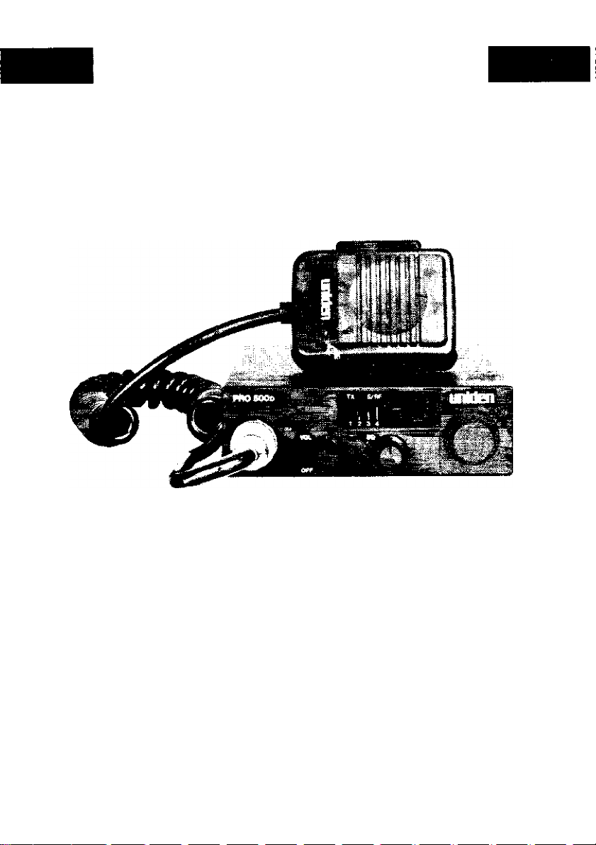
uniden*'
PRO 500d
Professional
Mobile CB radio
Page 2

Introduction
Welcome to the world of sophisticated, state-of-the-art CB radio communi
cations. Your Un/den PRO 500D represents the most advanced mobile radio ever
designed for use in the Citizens Band Radio Service. It will operate on any of the 40
AM frequencies authorized by the Department of Communications. Your PRO
500D features a superheterodyne circuit with PHASE LOCKED LOOP techniques
to assure precise frequency control. This radio has been type accepted and certifi
ed by the DOC.
Warning
Before transmitting with your transceiver, you must obtain a Department of Com
munications (D.O.C.) Citizens Radio Licence. Obtain an application form, from
the D.O.C. Before completing the form you should read the conditions governing
the licensing and operation of the C.R.S. (D.O.C. brochure RB 14). This brochure
also can be obtained from the D.O.C. After completing the application form, mail
it with the appropriate fee to the Superintendant Regulatory of Licensing in the
State or territory in which the station will be operated.
Connecting the Power Cords
With regard to the connection of the power cords, it may be possible or desirable
to connect the red lead (for negative ground systems) or the black lead (for positive
ground systems) to the ignition switch accessory terminal so that the radio is auto
matically turned off when the ignition switch (key) is turned off.
Aiternately, the power lead may be connected to an available terminal on the fuse
block or even to a point in the wiring harness. Care must be taken, however, to
guard against a short circuit condition. When in doubt, please contact your vehi
cle dealer for specific information about your vehicle.
Page 3
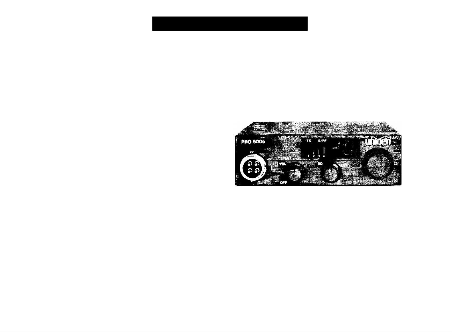
Controls and Functions
1. BuilMn ANL Circuitry — Help reduce h?rsh background noise caused by a
variety of interference sources.
2.
TX LED — An LED lights to indicate when the radio is transmitting.
3.
Microphone - The operational mode of the CB is controlled bythepush-to-
talk switch on the mic. Press the switch to activate the transmitter and disable
the receiver Release the switch to enable the receiver and disable the trans
mitter. When transmitting, hold the mic about 2 inches from your mouth and
speak clearly in a normal voice. The mic included with the PRO 500D is a de
tachable electret type.
4. S/KF METER — This LED meter shows the relative strength of the received
signal or the RE output.
5. Channel Indicator — Displays the channel currently in use.
6. Channel Selector — This switch selects the desired channel for transmission
and reception. All channels, except channel 9, may be used for communic
ations between stations operating under different license. Channel 9 has
been reserved by the D.O.C. for emergency communications involving the im
mediate safety of individuals or the immediateprotectionofproperty. Channel
9 also may be used to render assistance to a motorist. This is a D.O.C. rule and
applies to all operators of CB radios.
7. SQUELCH - The Squelch control is used to eliminate background noise dur
ing the absence of a transmission. Turn the control fully counter clockwise,
then slowly rotate it back, clockwise until all noise disappears. At this setting
any transmission must be slightly stronger than the background noise to
"Break Squelch" or to be heard. Further clockwise rotation will increase the
threshold at which a signal will be heard. You can select any level to "Break
Squelch"
8. Volume Control — Rotate clockwise to turn radio on and to increase volume.
Antenna Connector - This female connector permits connection of the trans
mission line cable male connector (PL-259) to the transceiver.
Page 4

Ooeration
Operating Procedure to Receive
1. Be sure that the power source, antennaandmicrophoneareproperlyconnected.
2. Turn the unit on by rotating the volume control clockwise.
3. Set the channel selector switch to the desired channel.
4. Set the volume control to a comfortable listening level.
5. Listen to the background noise from the speaker. Turn the squelch control
clockwise until the noise disappears (no signal should be present). Leave the
control at this setting. The squelch is now properly set. The receiver will re
main quiet until a signal is actually received. Do not advance the control too
far, or some weaker signals will not be heard.
Operating Procedure to Transmit
1. Be sure the operator has read and understands D.O.C. rules and regulations
prior to operating the transmitter.
2. Select the desired channel for transmission.
3. If the channel is clear, depress the push-to-talk switch on the side of the micro
phone and speak in a normal voice.
CAUTION: The transceiver Voltage Standing Wave Ratio (V.S.W.R.J measure
ment must be performed prior to the use of the transmitter. A “V.S.W.R." ratio in
excess of 2;1 may damage the transmitter. Please check your SWR reading fre
quently by using an SWR meter.
Preventative Maintenance
At six to twelve month intervals, the following system checks should be made;
1. Check the Voltage Standing Wave Ratio (V.S.W.R.)
2. Inspect all electrical connections.
3. Inspect antenna coaxial cable for wear.
4. Inspect all screws and other mounting hardware.
Page 5

Installation
Plan the location of the radio and microphone bracket before starting installation.
Select a location that is convenient for operation and does not interfere with the
driverorpassengerinthe vehicle. The radioshould be securely fastened to a solid
surface using the mounting bracket and self-tapping screws which are provided.
Mobile Antenna
Since the maximum allowable power output of the transceiver is limited by the
D.O.C., the antenna is a very important factor affecting transmission distance. It is
for this reason that we strongly recommend that you install only a quality antenna
in your new C6 radio system. You have purchased a superior quality transceiver.
Don't diminish its performance by installing an inferior antenna.
Only a properly matched antenna system will allow maximum powertransferfrom
the 50-ohm transmission line to the radiating element. We recommend that you
use an SWR meter when installing your antenna. Set your PRO 500D to channel
20 and make adjustments to the antenna until the meter reads as close to 1 as pos
sible. Your Uniden dealer is qualified toassistyou in the selection of the proper an
tenna to meet your application requirements.
For automobile installation, the whip antenna maybe used with good effect. The
most efficient and practical installation is a full quarter wave whip antenna
mounted on the rear deck or fender top, midway between the rear window and
bumper.
A short "loaded" whip antenna is more convenient to install on your automobile,
although the efficiency is less than a full quarter wave whip antenna.
For marine installation, consultyour dealer for information regarding an adequate
grounding system and prevention of electrolysis between fittings on the hull and
water.
Negative Ground S^em
If you are operating on a negative ground system, connect the red DC power cord
from the radio to the positive "-f" battery terminal or other convenient point and
connect the black power lead to the chassis or vehicle frame, or the negative "
terminal of the battery.
Positive Ground System
If you are operating on a positive ground system, connect the black DC power
cord from the radio to the negative "—"battery terminal or other convenient point
and connect the redpower lead to the chassis or vehicle frame, or the positive "-I-"
terminal of the battery.
Ground Information
Most newer cars and small trucks use a negative ground system, while some older
cars and some newer larger trucks may use a positive ground system. A negative
ground system Is generally identified by the "—"battery terminal being connected
to the vehicle motor block, but if you cannot determine the polarity of your vehi
cle, consult your vehicle dealer for information.
NOTE: This radio may be installed and used in any 12-volt DC negative or positive
ground system.
Page 6

Specifications
Channels:
Frequency Range;
Frequency Control;
Frequency Tolerance;
Operating Temp.;
Microphone:
Input Voltage;
Current Drain:
Size;
Weight;
Antenna Connector;
LED Meter;
TRANSMITTER
Power Output;
Modulation.
Freq. Response;
Output Impedance;
RECEIVER
Sensitivity;
Selectivity;
Image Rejection:
I.F. Frequency:
Automatic Gain Control;
Squeich;
Audio Output Power:
Freq. Response;
Distortion:
Internai Speaker;
40 AM
26.965 to 27.405 MHz
Phase Locked Loop (PLL) synthesizer
±0.005%
-30“C to +50“C
Piug in type; electret
13.8 VDC nom. (+ or — ground}
TX; fuli mod., I.7A
RX; with max audio output, I.7A
4-V,^"Wx6-3Vm"D>! I-'V32"H
1.6 lbs.
UHF, SO-239
indicates relative RF output and received sig
nal strength
4 watts
Class B amplitude modulation
300 - 2500 Hz
50 ohms, unbalanced
0.7juV for JOdB; (S + N)/N typical (limit:
1.2//V)
6dS a 7KHz, 70dB a lOKHz typical
SO dB typical
Double Conversion Superheterodyne
1st 10,692 MHz
2nd 450 KHz
(AGC); less than lOdB change in audio out
put for inputs from 10 to 50,000 microvolts
Adjustable; threshold less than !j«V
7 watts max. into 8 ohms
300 to 2000 Hz
less than 10% at 4 watts, lOOOHz
16 ohms, 5 watts round
Specifications and features are subject to change without notice.
Page 7

Troubleshootin
If your PRO 500D is not performing up to your expectations, please try these simple
steps. If you still cannot get satisfactory results after reading this manual and fol
lowing the trouble shooting steps, please call the Uniden Australia Pty. Ltd. at
599-3355.
Ifyou determine that service is necessary, contact your local dealerorpack the unit
in its original carton and send it along with a brief, concise description of the prob
lem, your name, address, phone number, and a copy of the original purchase re
ceipt to the address listed in the warranty.
TROUBLE CHECK
Unit will not turn on.
No power.
Poor reception
Weak transmission 1. Check antenna system, cable and connec
1.
Check power cord and all
connections.
Check power cord fuse.
2,
Check vehicle electrical system.
3.
Check and adjust Squelch.
I,
2. Check antenna system, cable and connec
tors.
3. Check operation mode of the radio.
tors.
2
Check antenna grounding.
3.
Check for corrosion on connectors.
Servicing your CB
Technical information, diagrams and charts will be provided upon request. It is
the user's responsibility to see that this radio is operating at ail times in accordance
with the D.O.C. Citizens Radio Service regulations. We highly recommend that
you consult a qualified radiotelephone technician forserviceandalignment of this
radio. When ordering parts, it is important to specify the correct model number
and serial number of this radio.
Piease refer to the WARNING information on the first page of this manual.
Page 8

Two Years Limited Warran
WARRANTOR: UMIDEN AUSTRALIA PTY. LTD, 345 Princes Highway, Rockdale,
N.S.W. 2216 ["UNIDEN").
ELEMENTS OF WARRANTY: UNIDEN warrants, for the duration of this war
ranty, its UNIDEN Product to be free from defects in materials and craftsmanship
with only the limitation or exclusions set out below.
WARRANTY DURATION; Thiswarrantyshall terminate and be of no further ef
fect Two (2} years after the date of original purchase of the Product or at the time
the Product is |a) damaged or not maintained as reasonable and necessary, (b)
modified, (c) improperly installed, (d) is repaired bysomeoneotherWarrantorfora
defect or malfunction covered by this Warranty, or(e) used in a manner or purpose
for which the Product was not intended.
PARTS COVERED: This Warranty covers all components of the Products,
STATEMENT OF REMEDY: In the event that the Product does not conform to
thisWarrantyatanytimewhilethis Warranty is effeaive. Warrantor will repair the
defect and return it to you prepaid, without charge for parts, service, or any other
costs incurred by Warrantor or its representatives in connection with the perform
ance of this Warranty. In addition, if the Productcontainsa defectormalfunction
which is not repaired aftera reasonable number of attempts by Warrantor to re
pair the Product, the Product or defective component will at our discretion, be re
placed without charge, when the defective product is delivered to the warrantor
at 345 Prince Highway, Rockdale, N.S.W. 2216 free and clear of all liens and en
cumbrances. Please note that while the Product will be remedied under this War
ranty without charge. THIS WARRANTY DOES NOT COVER OR PROVIDE FOR
THE REIMBURSEMENT OR PAYMENT OF INCIDENTAL OR CONSEQUENTIAL
DAMAGES.
PROCEDURE FOR OBTAINING PERFORMANCE OF WARRANTY: In the
event that the Product does not conform to this Warranty, the Product should be
shipped prepaid, to Warrantor at 345 Princes Highway, Rockdale, N.S.W. 2216.
THE ORIGINAL OR COPY OF THE SALES RECEIPT OR OTHER VALID EVIDENCE
OF THE DATE OF THE ORIGINAL PURCHASE MUST ACCOMPANY THIS PRO
DUCT.
Page 9

uniden*
345 Princes Highway, Rockdale, N.S.W. 2216
BRISBANE
3/12 Randall Street,
Slacks Creek,
Old. 4127
Phone |07) 290-1 188
Fax (07) 808 4251
MELBOURNE ft TASMANIA
446-448 Bel) Street,
East Preston,
VIC, 3072
Phone (03) 484 0373
Fax (03) 484 6057
Australia Pty. Ltd.
HEAD OFFICE:
Phone: 599 3355
Fax: (02) 599 7657
PERTH
23 Geddes Street,
Ba tea tta,
W.A, 6021
Phone (09| 344 3937
Fax (09) 349 8165
ADELAIDE
72-74 Halifax Street,
Adelaide
SA,. 5000
Phone (08) 223-4235
Fax (08) 223 1471
UTUA01317RZ
Printed in the Philippines
 Loading...