

Uniden PRO3600N4-4K, PRO1600N2-4K, PRO12800N0-4K, PRO800N2-5MP, PRO6400N0-4K User Manual
...Page 1

UNIDEN ProSERIES
USER’S GUIDE
This User’s Guide applies to the following models:
PRO800N2-4K
PRO1600N2-4K
PRO3600N4-4K
PRO6400N0-4K
PRO12800N0-4K
PRO800N2-5MP
PRO1600N3-5MP
© 2018 Uniden America Corporation Issue 1, April 2018
Irving, Texas
Page 2

Uniden surveillance products are not manufactured and/or sold with the intent to be used for illegal
purposes. Uniden expects consumer’s use of these products to be in compliance with all local,
state, and federal law. For further information on video surveillance and audio recording legal
requirements, please consult your local, state and federal ofcials.
Uniden constantly works on improving our products. This includes updating our documentation
with the latest rmware changes. Go to www.uniden.com to nd the latest version of all
documentation.
© 2018 Uniden America Corporation
All rights reserved.
Page 3

CONTENTS
INTRODUCTION ..................................................................................... 5
FIRMWARE AND DOCUMENTATION UPDATES ................................ 5
FEATURES ........................................................................................... 5
INCLUDED IN THE BOX ....................................................................... 5
INSTALLING YOUR SYSTEM
.....................................................................................6
PRO12800N0-4K ...............................................................................6
PRO6400N0-4K .................................................................................6
PRO3600N4-4K .................................................................................7
PRO1600N3-5MP ..............................................................................8
PRO800N2-5MP ................................................................................8
PRO1600N2-4K/PRO800N2-4K ........................................................8
CONNECT TO POWER ........................................................................ 9
INSTALL CAMERAS ............................................................................. 9
Installation Tips ..................................................................................9
BASIC OPERATION ............................................................................. 11
TAB OVERVIEW ................................................................................. 11
INITIAL SETUP ................................................................................... 12
OPERATION QUICK REFERENCE .................................................... 13
SCREEN DESCRIPTIONS .................................................................... 14
PREVIEW SCREEN ............................................................................ 14
PLAYBACK MAIN TAB ........................................................................ 14
BACKUP MAIN TAB ............................................................................ 15
CHANNEL SETTING MAIN TAB ......................................................... 16
Channel Connecting Side Tab .........................................................16
Channel Parameter Side Tab ........................................................... 16
Schedule Setting Side Tab ............................................................... 21
Manual Operation Side Tab .............................................................23
Channel Grouping Side Tab ............................................................. 24
Smart Side Tab ................................................................................25
DISK MANAGER MAIN TAB ............................................................... 25
Page 4

Storage Management Side Tab .......................................................25
Disk Grouping Side Tab ...................................................................26
Disk Location Side Tab ....................................................................26
SYSTEM SETTING MAIN TAB ........................................................... 27
Time Setting Side Tab ...................................................................... 27
Channel Zone Setting Side Tab .......................................................28
Network Setting Side Tab .................................................................29
Alarm Management Side Tab ...........................................................32
User Management Side Tab ............................................................34
PTZ Setting Side Tab ....................................................................... 36
Device Setting Side Tab ................................................................... 37
MAINTENANCE MAIN TAB ................................................................ 37
System Information Side Tab ........................................................... 37
Log Information Side Tab ................................................................. 39
Cong Management Side Tab ..........................................................40
System Upgrade Side Tab ...............................................................41
Auto Maintenance Side Tab ............................................................. 42
Network Monitoring Side Tab ........................................................... 42
FIRMWARE UPDATES ......................................................................... 44
TROUBLESHOOTING .......................................................................... 45
SPECIFICATIONS ................................................................................ 47
FCC PART 15/IC COMPLIANCE .......................................................... 50
THREE-YEAR LIMITED WARRANTY .................................................. 51
Page 5

INTRODUCTION
This User’s Guide provides basic instructions to install the NVR receiver and more detailed
rmware operation information. A series of informational articles can also be found at support.
uniden.com/Pro-series.
FIRMWARE AND DOCUMENTATION UPDATES
Because Uniden strives to provide the latest technology and quality in all of its products, rmware
updates may be available with no prior notice. Check for updates at support.uniden.com/pro-
support. Update the rmware manually either locally or remotely through a web browser.
FEATURES
The NVR provides a high-performace security network using a standard H.264 video compressed
format. It can be used as a stand alone device or online as a part of a video surveillance network.
With its professional network video surveillance software, it supports:
• Real-time recording up to 30 fps per channel.
• 24/7 surveilance-grade hard drive.
• Continuous, scheduled, and motion recording.
• H.264/H265 video compression.
• PTZ cameras supported, and can be remotely controlled through a mobile app.
• Accurate time stamps with NTP & daylight savings time.
• Digital zoom in live view and playback.
• HDMI video output with VGA on specic models.
• USB backup to connected USB devices and ash drives.
• Upgradeable rmware.
• Supports Internet Explorer, Safari, Chrome, and FireFox.
• Free Uniden ProSeries Mobile App (iOS and Android compatible) with live viewing, playback,
video recording, and snapshot capability.
• Instant email alerts with attached snapshots.
INCLUDED IN THE BOX
Hardware included varies according to the specic model. Check the box itself for a hardware list.
If any items are missing or damaged, visit www.uniden.com for assistance.
QUICK START GUIDE ATTRIBUTES
This Quick Start Guide may refer to specic screens in the procedures. The QSG follows these
conventions:
• Italic text indicates a screen name, menu selection, etc. It is usually prefaced with “Select.”
• BOLD text indicates an action, such as Save, Copy to, etc. It is usually prefaced with “Click.”
5
Page 6
PRO12800N0-4K
INSTALLING YOUR SYSTEM
1. Power Switch
2. 110-220VAC Power Supply Plug
3. LAN1/LAN2 Interface
4. Audio Output
5. HDMI Video Output 2
6. VGA Video Output 2
7. VGA Video Output 1
8. HDMI Video Output 1
9. USB 3.0
Cameras connect to LAN1 (PoE gigabit network switch)
10. E-Sata Interface 1
11. Alarm Input
12. Alarm Output (1, 2, 3, 4)
13. RS422 Interface
14. Alarm Output (5, 6, 7, 8)
15. RS232
16. E-Sata Interface 2
17. Audio Input
PRO6400N0-4K
6
Page 7
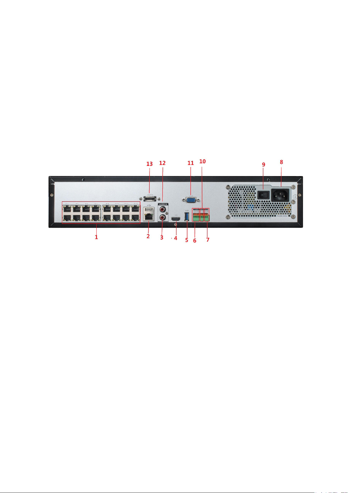
1. USB 2.0
9. Alarm Input (1-4)
2. Audio Input
3. E-SATA
4. Alarm Input (5-16)
5. Power Switch
6. 110-220VAC Power Supply Plug
7. RS485
8. Alarm Output
Cameras connect to LAN1 (PoE gigabit network switch)
10. USB 3.0 Alarm Output
11. HDMI Video Output
12. VGA Video Output
13. Audio Output
14. LAN 1
15. LAN 2
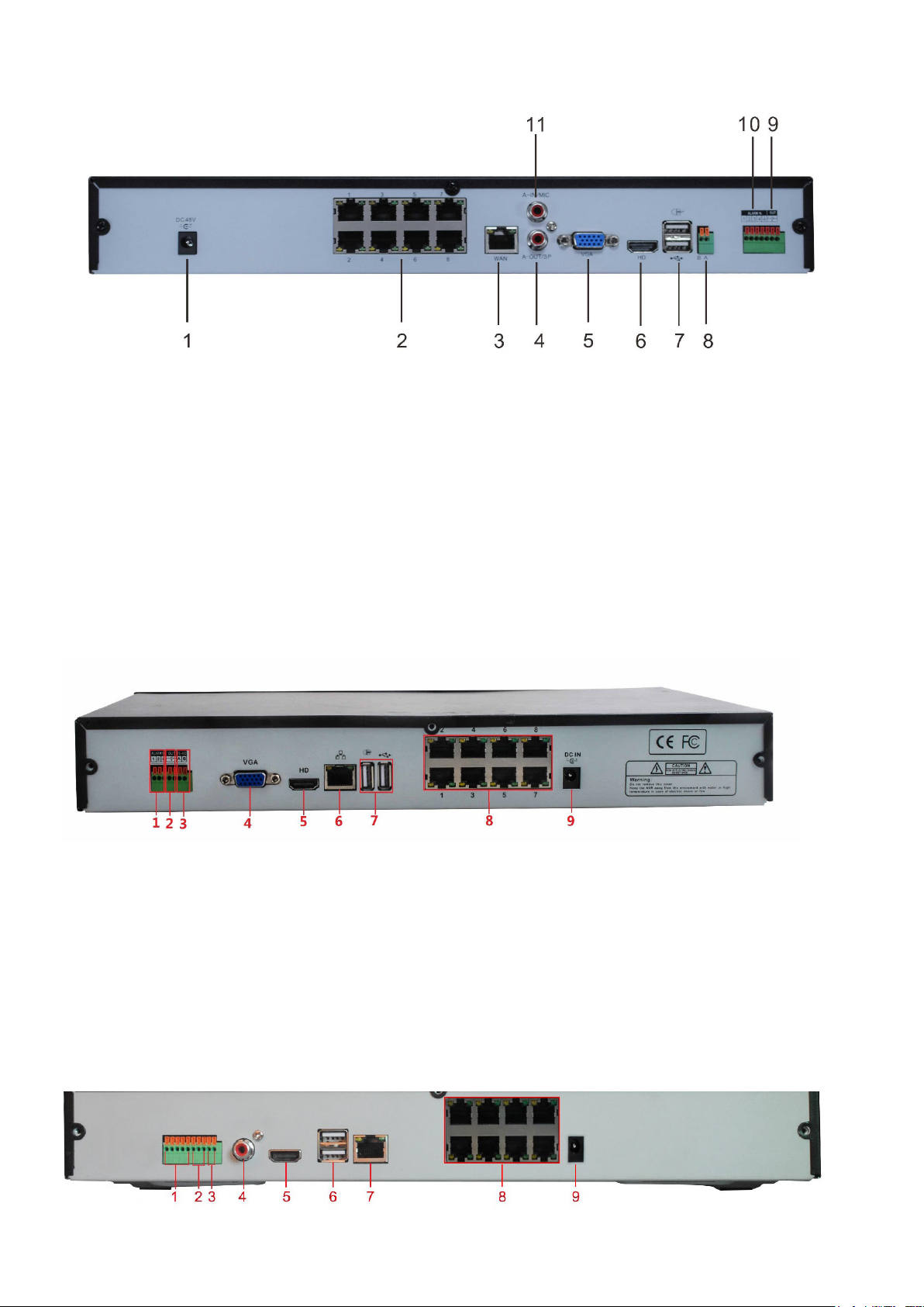
PRO3600N4-4K
1. PoE Camera Ports
2. RJ45 Network Interface (LAN1)/
USB2.0
3. Audio Output
4. HDMI Video Output
5. USB 3.0
6. Alarm Input
Cameras connect to LAN1 (PoE gigabit network switch)
7. Alarm Output
8. RS485 Interface
9. Power Switch
10. 110-220VAC Power Supply Plug
11. VGA Video Output
12. Audio Input
13. E-SATA
7
Page 8
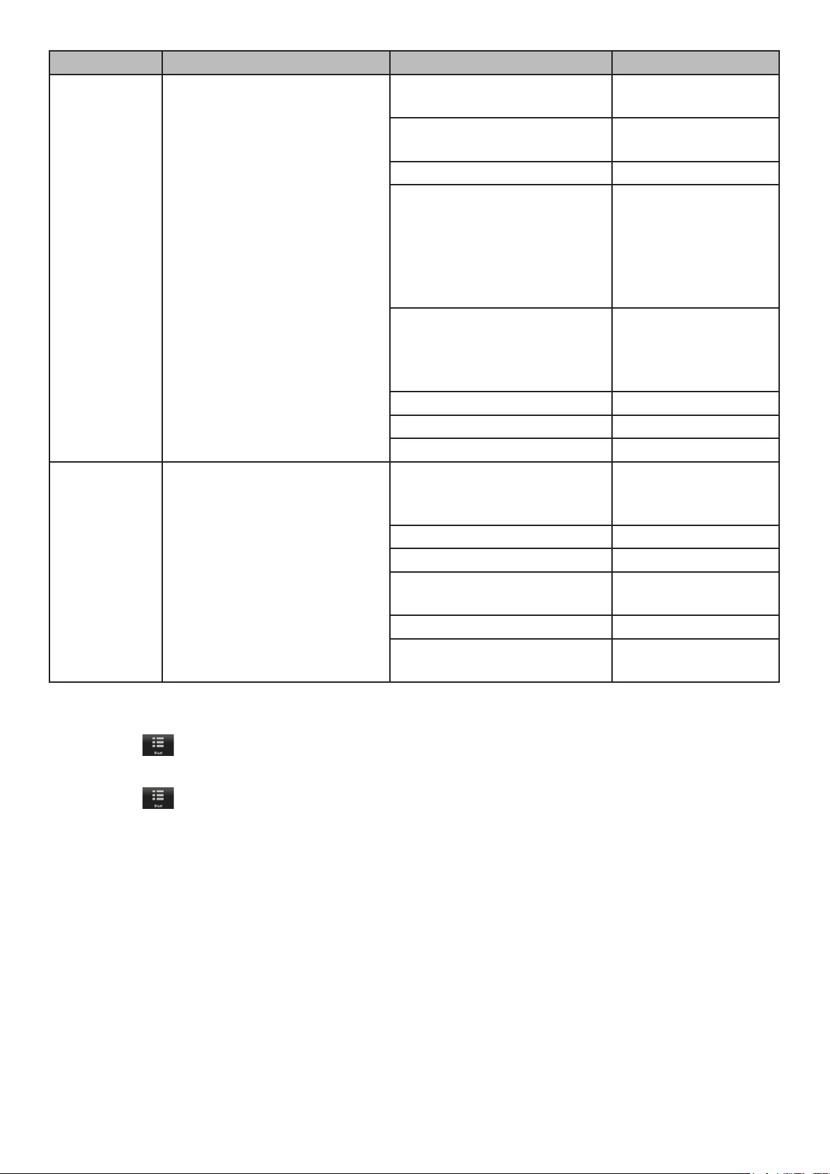
PRO1600N3-5MP
1. DC48V
2. PoE Camera Ports
3. RJ45 Network Interface
4. Audio Output
5. VGA Vido Output
6. HDMI Video Output
PRO800N2-5MP
7. USB 2.0
8. RS485
9. Alarm output
10. Alarm Input
11. Audio Output
1. Alarm Input
2. Alarm Output
3. RS485
4. VGA Video Output
5. HDMI Output
PRO1600N2-4K/PRO800N2-4K
8
6. RJ45 Network Interface
7. USB 2.0
8. PoE Camera Ports
9. DC48V
Page 9

1. Alarm Input
6. USB 2.0
2. Alarm Output
3. RS485
4. Audio Output
5. HDMI Video Output
7. RJ45 Network Interface
8. PoE Camera Ports
9. DC15V
CONNECT TO POWER
Connect the power cabling to an easily accessible AC socket outlet.
INSTALL CAMERAS
Video surveillance laws vary from state to state. Check local regulations to be sure you are
operating in a legal manner.
See the IP Camera Installation Guide for detailed installation procedures.
Installation Tips
• When selecting an outside location for your cameras, keep in mind that most cameras
are designed to operate between 14°F to 122°F (-10°C to 50°C) with a relative humidity
of up to 95%. Avoid installing cameras in direct sunlight, and consider wind chill and other
environmental factors, too.
• Mount the camera in an area that is visible, but out of reach. Route the wiring so it does not
interfere with power or telephone/cable lines and it should not be where it could be easily cut.
Create a plan for camera wire routing and for camera angle.
• Adjust the camera angle so that it covers an area with high trafc as needed. In “high-
risk” locations, have more than one camera cover the same area. This provides camera
redundancy if a vandal attempts to damage a camera.
• If you position cameras indoors, avoid pointing the camera at a glass window to see outside.
This may result in a bright white ring in the night vision image because the light from the night
vision LEDs may reect off the window glass.
• If installed outdoors, the cable and all cable connections must be routed inside the wall.
Take the following placement suggestions under consideration:
• Cabling Distance From NVR to Camera. The video signal sent from the camera to the DVR
is reduced over distance. The maximum distance allowed is 330 feet (100 meters). A 60 foot
cable is included. If you need a cable longer than 60 feet, then use an RG59 cable (with
suitable connectors).
• Do not submerge any camera.
• Mounting. Ensure the camera is mounted on a stable surface which is capable of supporting 5
times the weight of the camera.
• Avoid direct exposure to the weather. Cameras which are weatherproof may be mounted
outside, such as under an eave or other overhang; however, the image will be affected by rain,
etc., landing on the lens. Do not allow direct sunlight to land on the lens.
9
Page 10

10
Page 11

BASIC OPERATION
The NVR Preview screen, which displays live video, acts as the network’s “main” screen. From
here, you can select an icon across the top of the screen to access other operations.
Many screens have several tabs on the screen. These tabs are referred to as Main tabs, Side
tabs, and Top tabs. When referencing a specic screen progression, the text references Main
tabs/Side tabs/Top tabs in that order. For example, the illustration below would be referenced as
System Setting/Network Setting/Basic Setting.
TAB OVERVIEW
MAIN TAB PURPOSE SIDE TAB TOP TABS
Start Log in/out, initial setup,
reboot, and shut down
Preview View live streaming, activate
groups and tours after setup
Playback View recorded video,
snapshots, and external les
Backup Back up les from selected
channels
Channel
Setting
Disk
Manager
Connects channels to the
system, sets recurring
recording schedules, and
sets of channel groups.
Shows disk storage details
and sets up disk grouping.
NA NA
Channel List/Groups/Tours NA
HDD Info/Video Setting NA
PTZ/Preset/Cruise/Pattern NA
Playback Mode NA
Channel List/Groups NA
File Search NA
Search Type NA
Local Backup NA
Channel Connecting Search
Add All
Details
Import/Export
Channel Parameter Display Setting
Video Encoding
Snapshot
Motion
Video Loss
Video Tampering
Privacy Mask
Schedule Setting Recording Setting
Timing Snapshot
Manual Operation Manual Red
Snapshot
Manual Alarm
Channel Grouping Groups
Tour Groups
Smart Target Count
Object Left/Lost
Area Detection
Line Crossing
Storage Management NA
Disk Grouping NA
Disk Location Map NA
11
Page 12
MAIN TAB PURPOSE SIDE TAB TOP TABS
System
Setting
Maintenance Provides rmware version
Congures system (time,
email and other network
settings, alarm and user
management, PTZ, and
device)
number. Saves network
conguration and allows
conguration update.
Time Setting Device Time
IPC Timing
Channel Zero Setting Global Setting
Channel Setting
Network Setting Basic Setting
DDNS Setting
Email Setting
Advnced Setting
Management
Platform
Telnet Settling
Alarm Management Alarm Input
Alarm Output
Abnormal Setting
Linkage Setting
User Management NA
PTZ Setting NA
Device Setting NA
System Information Device Information
Stream Information
Online User
Log Information NA
Cong Management NA
System Upgrade Local Upgrade
Upgrade IPC
Auto Maintenance NA
Network Monitoring Network Flow
Network Test
INITIAL SETUP
1. Click the icon; select LOGIN. Enter admin (user name), skip password for now, and then
click Login.
2. Click the
conguration:
• Language setting: Default: ENGLISH; click Next.
• Display setting: Sreen resolution default: 1920x1080-P60; click Next.
• Network setting: Check Network Card dropdown list for Network Card. If you only have one LAN
port, do not set a static IP address and leave DHCP enabled. If you have more than 1 LAN port,
disable DHCP and write down the IP address, mask, and gateway that the DHCP server/router
assigns. Click Next.
• Uniden ProSeries: QR codes display to download the Uniden ProSeries app. Apple QR code
downloads app for iOS version and Android QR code downloads the Android version.
3. Check the Next time no longer display box in lower left corner. This series of screens will not
display for further startups.
4. Click Finish. The Preview screen displays.
icon again; select GUIDE. Go through these screens to provide a basic system
12
Page 13

OPERATION QUICK REFERENCE
TO DO THIS
MAIN TAB SIDE TAB TOP TAB
GO TO
Set system time System Setting Time Setting Device Time
Set up email System Setting Network Setting Email Setting
Add users and set up
System Setting User Management NA
passwords
Set motion sensitivity Channel Setting Channel Parameter Motion
Set up alarms System Setting Alarm Management Alarm Input
(or Alarm Output)
Enable/disable DDNS System Setting Network Setting DDNS Setting
Check and update rmware Maintenance System Information Device Information
Set IP channels Channel Setting Channel Connecting NA
Record Video
Manually
Scheduled
From Preview screen, right click on a channel screen. Select
Start Recording.
Channel Setting Schedule Setting Recording Setting
Search for Files, Snapshots Playback NA NA
Play back video Playback NA NA
Mask motion sensitive areas Channel Setting Channel Parameters Motion
Block off areas to not record Channel Setting Channel Parameters Privacy Mask
View Channel Preview NA NA
Back up video les Backup Local Backup
Check users currently on the
Maintenance System Information Online User
network
Download the mobile app System Setting Network Setting QR Code
13
Page 14
SCREEN DESCRIPTIONS
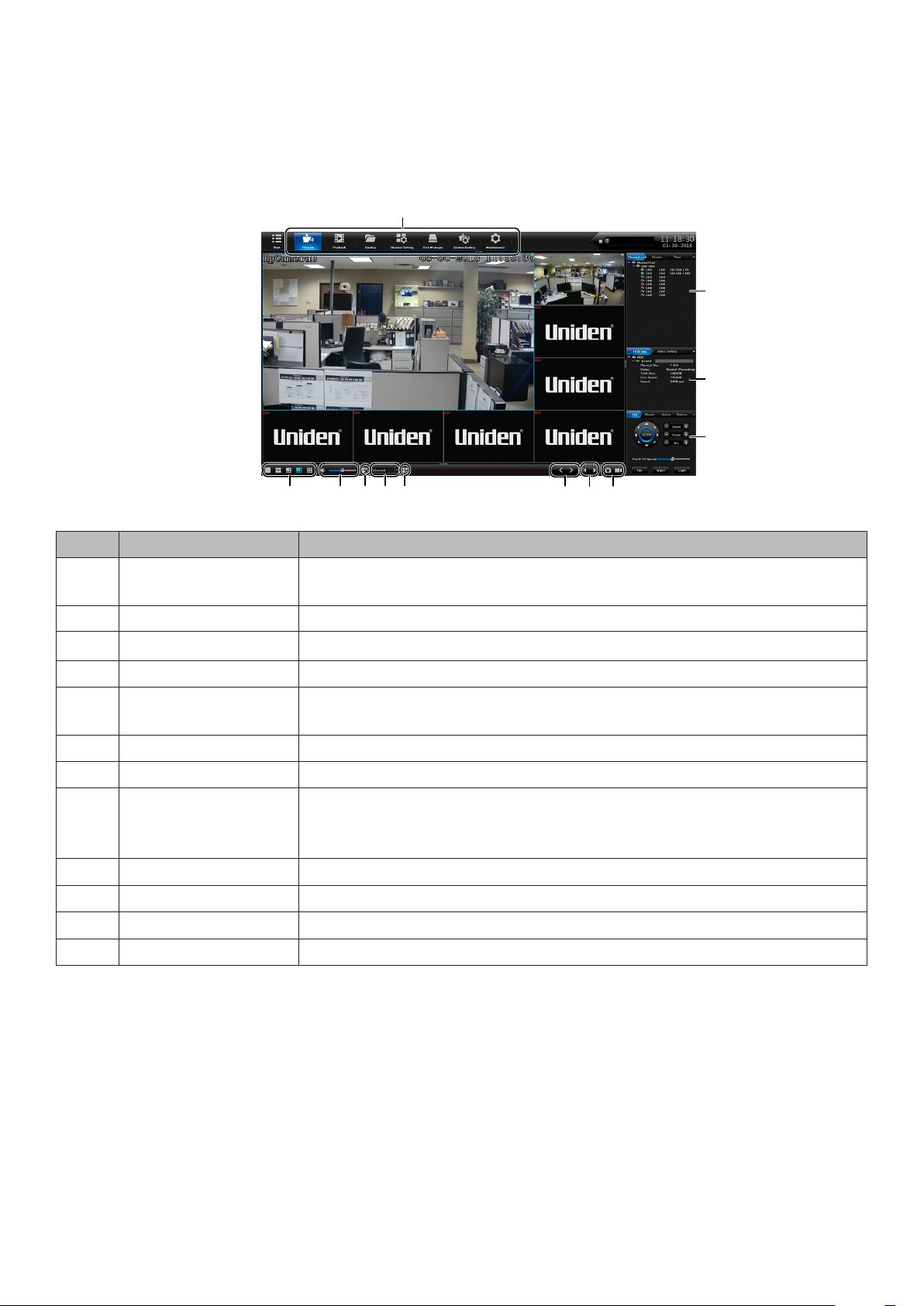
PREVIEW SCREEN
Select Preview; The Preview screen displays. This screen does not have Side, or Top tabs.
However, various elements on the screen make operation easier
12
11
10
9
1
12
1 2 3 4 5
876
NO. ELEMENT DESCRIPTION
1 Screen
conguration
Sets how the screens are displayed (single screen, 4 in one
display, etc.).
2 Volume Adjusts the volume.
3 Tour Select a Tour Group.
4 Speed Set how quickly the images change in a tour group.
5 Open Linkage
???
Preview
6 Page UP/DOWN Page up, page down
7 Last/Next Group Goes to previous or next group
8 Take Snapshot
Start/Stop
Take snapshot of current image on selected channel.
Click to start and stop recording.
Recording
9 PTZ Set PTZ camera orientation and cruise patterns.
10 HDD Info. Physical information about HDDs
11 Channel List Estabish Groups and Tours
12 Main Tabs Links to other areas of the NVR rmware
PLAYBACK MAIN TAB
Use the Playback Main tab to select a channel. You can then play back a recorded les and view
snapshots.
14
Page 15
12
6
5
4
1
2
3
NO. ELEMENT DESCRIPTION
1 Video Controls Click each icon to control different aspects of playing back video.
2 Playback Control Click on timeline to skip playback to that spot.
3 Search Select search parameters.
4 File Search Select search dates.
5 Channel List/
Select a channel or a group to search .
Groups
6 Playback Mode Select recorded, external, or snapshot
BACKUP MAIN TAB
Use the Backup Main tab to select les to backup from 1 or more channels.
FIELD DESCRIPTION
Select CH Select one or more channels (or all channels) to back up.
15
Page 16
FIELD DESCRIPTION
Search Type Select a le type to search for:
• All
• Smart
• Moon
• Alarm
• Normal
• ANR
File Time Enter a time frame to search for les.
File Format Select wither I8 or AVI.
File Size Select a le size to search for.
Storage Location Browse to the location where the les will be backed up.
Total U-disk Space Total U-Disk space available
Free U-disk Space Remaining U-Disk space
Backup progress Backup progress status bar
Click each icon to control different aspects of playing back video.
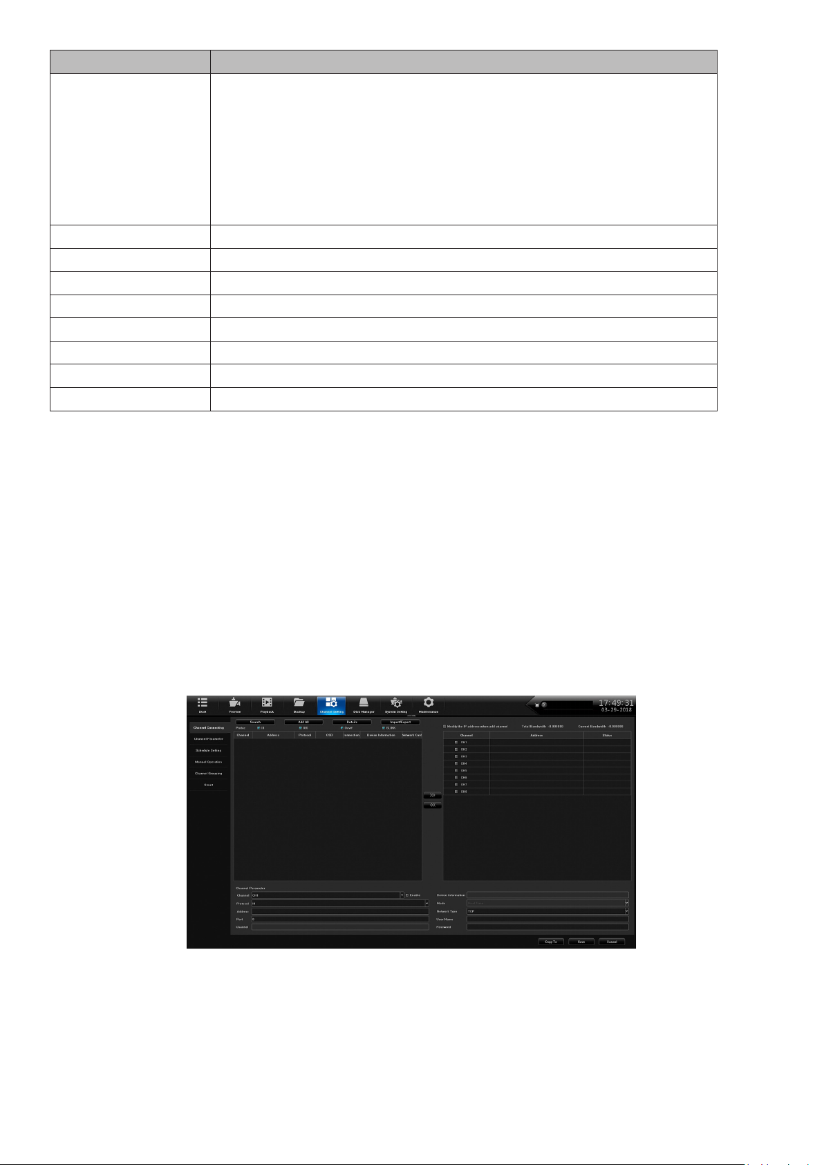
CHANNEL SETTING MAIN TAB
The Channel Setting Main tab lets you add cameras to your network, set up automatic and manual
recording schedules, and set up channel groups. It is comprised of the following side tabs:
• Channel Connecting
• Channel Parameter
• Schedule Setting
• Manual Operation
• Channel grouping
Channel Connecting Side Tab
Use this tab to nd cameras and connect them to your NVR.
Channel Parameter Side Tab
This side tab has 7 top tabs:
• Display Setting
• Video Encoding
• Snapshot
16
Page 17

• Motion
• Video Loss
• Video Tampering
• Privacy Mask
Display Setting Top Tab
FIELD DESCRIPTION
Channel Select the channel to edit from a dropdown list.
Display Local
Channel Name
Local Channel
Name
Display Local
Camera Name
Local Camera
Name
Show Time/Date Check to display the time/date on the screen.
Time Format Select 12-hour or 24-hour format to display the time.
Date Format Select a date format from a dropdown list.
Image Setting Set brightness, contrast, saturation, and hue levels.
Lens Parameters Set parameters for such as auto/manual exposure, trigger levels,
Check to display the local channel name on the screen.
Create or edit the channel name. A popup keyboard displays.
Check to display the local camera name on the screen.
Create or edit the camera name. A popup keyboard displays.
picture modes, and more.
17
Page 18

Video Encoding Top Tab
FIELD DESCRIPTION
Channel
Stream Type Select Main Stream or Sub Stream.
Video Type Select Video or Video and Audio
Resolution Enter the video resolution.
Bit-Rate Type Select CBR or VBR
Bit Rate Enter the bit rate.
Frame Rate Enter the frame rate.
Encoding Type Enter the encoding type.
I Frame Interval Enter the I Frame Interval.
Snapshot Top Tab
Set up snapshot parameters.
FIELD DESCRIPTION
Channel Select a channel to take snapshots.
Resolution Sekect an image resolution for the snapshot.
18
Page 19

FIELD DESCRIPTION
Snapshot Time
Interval
Set how long the system pauses between snapshots.
Motion Top Tab
FIELD DESCRIPTION
Channel Select a channel.
Detect Mode Select either Camera or NVR.
Enable Motion
Detection
Arming Schedule Arming Schedule popup screen displays to set up to 8 snapshots
Linkage Alarm Linkage popup screen displays to set alarm linkage
Full Screen Grid displays over image area to indicate areas that WILL trigger
Delete All Delete grid.
Set motion detection Sensitivity and Proportion.
per 24 hour period. Can also copy schedule to all or selected days.
parameters.
motion detection. Right click and hold on the screen, then drag a
box over the areas you do NOT want to trigger motion detection.
That box will delete the grid lines, indicating that that specic area
will NOT trigger motion detection. Click Save.
Video Loss Top Tab
When video loss is enabled, you can set up a schedule to monitor for it.
19
Page 20

FIELD DESCRIPTION
Channel Select a channel
Enable Video Loss Select to allow video loss monitoring.
Arming Schedule Arming Schedule popup screen displays to set up to 8 arming
periods per 24 hour period. Can also copy schedule to all or
selected days.
Linkage Setting Popup displays to select linkage type, alarm output, PTZ Linkage,
and linkage status on channels.
Video Tampering Top Tab
Like the Video Loss top tab, this screen sets up video tampering monitoring.
FIELD DESCRIPTION
Channel Select a channel.
Enable Privacy
Mask
Arming Schedule Arming Schedule popup screen displays to set up to 8 arming
20
Select to allow privacy masking
periods per 24 hour period. Can also copy schedule to all or
selected days.
Page 21

FIELD DESCRIPTION
Linkage Setting Popup displays to select linkage type, alarm output, PTZ Linkage,
and linkage status on channels.
Delete All Delete all settings.
Privacy Mask Top Tab
Privacy masking lets you mark off an area of the screen to not be recorded. These areas could
range from the lower half of a room (close to the oor to avoid pets triggering motion detection) to
a keypad on an ATM.
Left click in the live view and drag out a square or rectangle.
Click Save and the area slected turns black.
FIELD DESCRIPTION
Channel Select a channel.
Enable Privacy
Mask
Delete All Delete all unsaved masks.
Select to allow privacy masking
Schedule Setting Side Tab
Channel Setting has two top tabs:
• Recording Setting
• Timing Snapshot
Recording Setting Top Tab
This top tab helps you set up a 24-hour recording schedule for Monday - Sunday.
21
Page 22

FIELD DESCRIPTION
Channel Select a channel to get a snapsho schedule established.
Record Select a recording mode from the dropdown list.
Enable ANR Check to enable Automatic Network Recovery.
Only applicable if the camera has a microSD card.
Schedule Click Setting to display the Arming Schedule popup screen to set 1 to 8
recording periods per 24 hour period. Can also copy schedule to all or selected
days. When the schedule is saved and the window is closed, the schedule
reects in the blue schedule display.
Pre-record Select the number of seconds to be recorded before the scheduled recording
begins.
Post-record Select the number of seconds to be recorded after the scheduled recording ends.
Timing Snapshot Top Tab
Timing Snapshot helps you establish a schedule to automatic snapshots from your cameras. it is
similar to Recording Setting top tab.
FIELD DESCRIPTION
Channel Select a channel to get a snapshot schedule established.
Timing Snapshot Check to enable a schedule to be set up.
Snapshot Schedule Click Setting to display the Arming Schedule popup screen to
set 1 to 8 snapshot periods per 24 hour period. Can also copy
schedule to all or selected days. When the schedule is saved and
the window is closed, the schedule reects in the blue schedule
display.
22
Page 23

Manual Operation Side Tab
This side tab has three top tabs:
• Manual Rec
• Snapshot
• Manual Alarm
Manual Rec Top Tab
The Manual Recording top tab lets you allow manual recording on all channels or specic
channels.
FIELD DESCRIPTION
Manual Rec Select ALL to allow manual recording on all channels.
CH1-X Select a specic camera or cameras to allow manual recording.
Snapshot Top Tab
The Snapshot top tab lets you take snapshots on all channels or specic channels.
FIELD DESCRIPTION
Snapshot Select ALL to allow snapshots on all channels.
23
Page 24

FIELD DESCRIPTION
CH1-X Select a specic camera or cameras to allow snapshots.
Manual Alarm Top Tab
This tab provides a list of the alarm output numbers, their alarm names, and whether or not the
alarms are enabled (able to be triggered).
FIELD DESCRIPTION
Trigger Set a selected alarm to trigger. Also, cancel all triggered alarms if
All Trigger selected.
All Trigger Select All alarms to trigger.
Delete All Delete all alarms.
Channel Grouping Side Tab
Channel Grouping has two side tabs:
• Group
• Tour Groups
Groups Top Tab
The Groups top tab lets you set up groups and add channels to those groups. For example, you
may have a group called Front Lobby and add all cameras related to the front lobby (Front Door,
Lobby ATM, etc) to that group. The center icons let you add, delete, reorder, and name the tour
groups..
24
Page 25

Tour Groups Top Tab
Once you have groups set up, you can arrange them in a specic order for display. For example,
you can have all Lobby group cameras display, then all Back Entrance cameras disaplay, etc. The
center icons let you add, delete, reorder, and name the tour groups.
Smart Side Tab
This side tab displays the analytic features that are available according to speciic camera models.
Not every top tab displays for every camera.
Common analytic tabs are:
• Target Count -
• Object Left/Lost
• Area Detection
• Line Crossing
1. For each of the Smart top tabs, enable the feature.
2. Set up the features of each tab and save.
3. From Preview, select the circle icon in the bottom icon bar. This will allow the analytics to
display on the screen.
DISK MANAGER MAIN TAB
The Disk Manager Main tab lets you manage storage requirements and channel groups. It also
provides an image of your model’s motherboard, highlighting HDD locations. It has the following
side tabs:
• Storage Management
• Disk Grouping
• Disk Location Map
Storage Management Side Tab
The Storage Management tab gives you information about the HDDs and their current capacities.
There are two editable elds:
25
Page 26

• Missing Alarm - Check this eld to allow an alarm if the system cannot detect the HDD. Click
Save.
• Format - Check this eld to reformat the HDD. Click Format.
Disk Grouping Side Tab
The Disk Grouping side tab lets you assign cameras to different HDDs if your system has more
than one HDD.
FIELD DESCRIPTION
Auto Grouping Select to have the system automatically group the channels on
HDDs.
Manual Grouping Select to manually group the channels on HDDs.
Disk Location Side Tab
The Disk Location side tab shows a photo of that models motherboard, highlighting the HDD
locations.
26
Page 27

Representation only; images are unique to each model.
SYSTEM SETTING MAIN TAB
The System Setting main tab establishes system conguration.It has the following side tabs:
• Time Setting
• Channel Zero Setting
• Network Setting
• Alarm Management
• User Management
• PTZ Setting
• Device Setting
Time Setting Side Tab
The Time Setting Side Tab has two top tabs:
• Device Time
• IPC Setting
. Line Crossing Top Tab
Device Time Top Tab
Use this tab to set time of day, date format, time zone, daylight savings time, and NTP.
27
Page 28

FIELD DESCRIPTION
Device Time Adjust time and date through a popup keypad. Click Modify to
save the change.
Date Format Select a format style from a dropdown box to display the date.
Time Zone Select local time zone.
Time Zone
Adjustment
Enable Daylight
Savings Time
DST Start
DST End
DST Bias
NVR systems have a CMOS clock button cell battery located on the PC board to maintain time
should power fail.
CAUTION! RISK OF EXPLOSION IF BATTERY IS REPLACED WITH AN INCORRECT
TYPE. DISPOSE OF USED BATTERIES ACCORDING TO INSTRUCTIONS.
MISE EN GARDE! RISQUE D’EXPLOSION SI LA PILE EST REMPLACÉE PAR UNE PILE
DE TYPE INCORRECT. VEUILLEZ JETER LES PILES USÉES EN RESPECTANT LES
INSTRUCTIONS.
Fine tune the time zone if needed.
Check this eld to enable daylight savings time.
Enter the start and end month/day/time that DST starts and ends.
IPC Timing Top Tab
This top tab allows you to enable or disable the following:
• Auto Timing
• Reconnect Timing
• Timing Correction
Channel Zone Setting Side Tab
Channel Zero compresses selected cameras into a single image when using the mobile app.
The Time Setting side tab has two top tabs:
• Global Setting
• Channel Setting
28
Page 29

Global Setting Top Tab
Select Enable to congure the channels for viewing on the app.
Channel Setting Top Tab
1. Select the multiview icon below the screen setup. the screen divides into the number of
screens on the icon.
2. Select a channel to display in that location. that channel number disaplays on the screen.
3. Repeat for all channels.
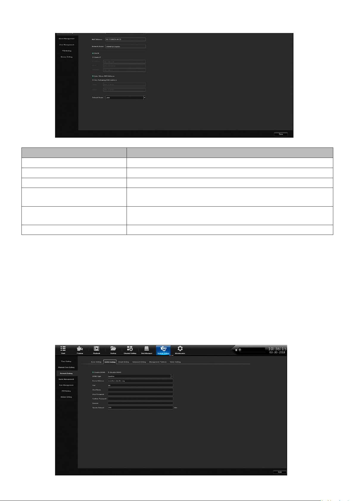
Network Setting Side Tab
The Network Setting side tab provides DDNS, email setting, and other network conguration
screens. It has six top tabs:
• Basic Setting
• DDNS Setting
• Email Setting
• Advanced Setting
• Management Platform
• Telnet Setting
29
Page 30
Basic Setting Top Tab
FIELD DESCRIPTION
Network Card Select the applicable LAN.
MAC Address MAC address displays.
Network Status Network status displays.
DHCP / Static IP Select DHCP or Static IP. If selecting Static IP, IP Address,
Mask, and Gateway elds display
DNS Address Use the automatically selected DNS address or enter DNS
addresses
Default Route LAN for route displays
DDNS Setting Top Tab
Select Enable or Disable DDNS. If DDNS is enabled, the following elds can be edited:
• DDNS Type
• Server Address
• Port
• User Name
• User Password
• Conrm Password
• Domain
• Update Interval (minutes)
30
Page 31

Email Setting Top Tab
With email set up, the system can notify you of alarms and other activity. Double-click on the
following elds to set up email contacts through a popup keyboard.
• Sender Email
• Password
• Conrm Password
• User Name
• Email Address
Advanced Setting Top Tab
FIELD DESCRIPTION
Enable/Disable PPPoE Enable PPPoE to disaplay and set the following:
• PPPoE User Name
• Device Dynamic IP
• Password
• Conrm password
Enable/Disable UPnP Select this eld to enable UPnP.
Enable/Disable Rtsp Verify Select this eld to enable Rtsp Verify.
31
Page 32

Management Platform Top Tab
1. Select QR Code for the Device ID, Apple, and Andoid mobile apps. Use the QR codes
displayed to download the Uniden ProSeries mobile app for your specic platform..
2. Set up account in the app. When adding the device, use Device ID QR code from this screen or
from the sticker on the device itself.
Telnet Setting Top Tab
If you enable Telnet, be aware that there is a possibility of security issues resulting from a user on
one computer logging into another computer on the network.
Alarm Management Side Tab
The Alarm Managementlets you set up alarm input and output. It has four top tabs:
• Alarm Input
• Alarm Output
• Abnormal Setting
• Linkage Setting
32
Page 33

Alarm Input Top Tab
FIELD DESCRIPTION
Alarm Input Select alarm input source from dropdown menu.
Device IP Address Enter the device’s IP address
Alarm Input Name enter the alarm name from the popup keyboard.
Alarm Status Select Normally Open or Normally Closed.
alarm Handling If Alarm Handling is selected, you can access the Arming
Schedule and Linkage Schedule by selecting Setting.
Alarm Output Top Tab
FIELD DESCRIPTION
Alarm Output Select the alarm output from a dropdown list.
Alarm Output Name Click in this eld to enter a name for the alarm using the popup
keyboard.
Alarm Output Delay Use the dropdown menu to select an alarm output delay time in
seconds.
33
Page 34

FIELD DESCRIPTION
Arming Schedule Select Setting to enter an armng schedule in the Arming
Schedule popup screen.
Abnormal Setting Top Tab
Use this tab to establish the abnormal conditions that will trigger alarms.
FIELD DESCRIPTION
Abnormal Type Select an abnormal condition fro mthe dropdown list.
Trigger Mode Select a triggered alarm notication method.
Alarm Output Select ALL or 1.
Linkage Setting Top Tab
User Management Side Tab
This tab lets you add and delete users, modify existing user’s proles, and set user permissions
through action buttons on the bottom of the screen.
34
Page 35

Action Buttons
User Permission
Select a user and User Permission and the following screen displays:
FIELD DESCRIPTION
Local Permission Select local permissions to assign to the selected user.
Remote Permission Select remote permissions to assign to the selected user.
Multi-Channel Cong Select other channels to use this same conguration.
Delete User
Select a user to delete and click on Delete User. A Conrmation prompt displays.
Add User
Select Add User to add additional users to the network. The Add User screen displays, allowing
you to enter the following:
• User Name
• Password
• Conrm Password
• User Type
35
Page 36

Modify User
Select Modify User to change users’ network proles. The same Modify User screen displays,
allowing you to edit the following:
• User Name
• Password
• Conrm Password
• User Type
PTZ Setting Side Tab
The PTZ Setting screen establishes PTZ camera conguration. Set this conguration through the
following elds:
• Channel
• Protocol
• Decoder Address
• Baud Rate
36
Page 37

• Data Bits
• Stop Bits
• Parity
• Flow Control
Device Setting Side Tab
Use the Device Setting side tab to congure network basics such as device name, Language,
resolution, preview ability, and others.
MAINTENANCE MAIN TAB
System Information Side Tab
The System Information side tab has the following top tabs:
• Device Information
• Stream Information
• Online User
37
Page 38

Device Information Top Tab
This screen displays the current rmware version and its description.
Stream Information Top Tab
This tab lists the main and substream information in kb/s and MB/H for each channel.
Online User Top Tab
This tab lists each user and probides login information.
38
Page 39

Log Information Side Tab
FIELD DESCRIPTION
Main Types Select a type from the dropdown list.
DST Start/DST End Adjust DST start and end times.
Sub types Seect a sub type from the dropdown list.
39
Page 40

Cong Management Side Tab
This screen has 5 selections:
• Export Conguration
• Import Conguration
• Restore Default
• Backup to HDD
• Restore from HD
Export Conguraton/Import Conguration
These selections let you import or export conguration information from a USB drive or a mobile
HDD.
Restore Default
This selection brings up a screen to select what defaults you want to restore.
40
Page 41

Backup to HDD
Select this option and the NVR backs up to an HDD. A progress bar displays and then a backup
successful message displays.
Restore from HDD
Select this option and the NVR restores from a user-selected restoration point. A progress bar
displays and then a restore successful message displays
System Upgrade Side Tab
Upgrade the NVR (Local Upgrade top tab) or the IP camera (Upgrade IPC top tab).
41
Page 42
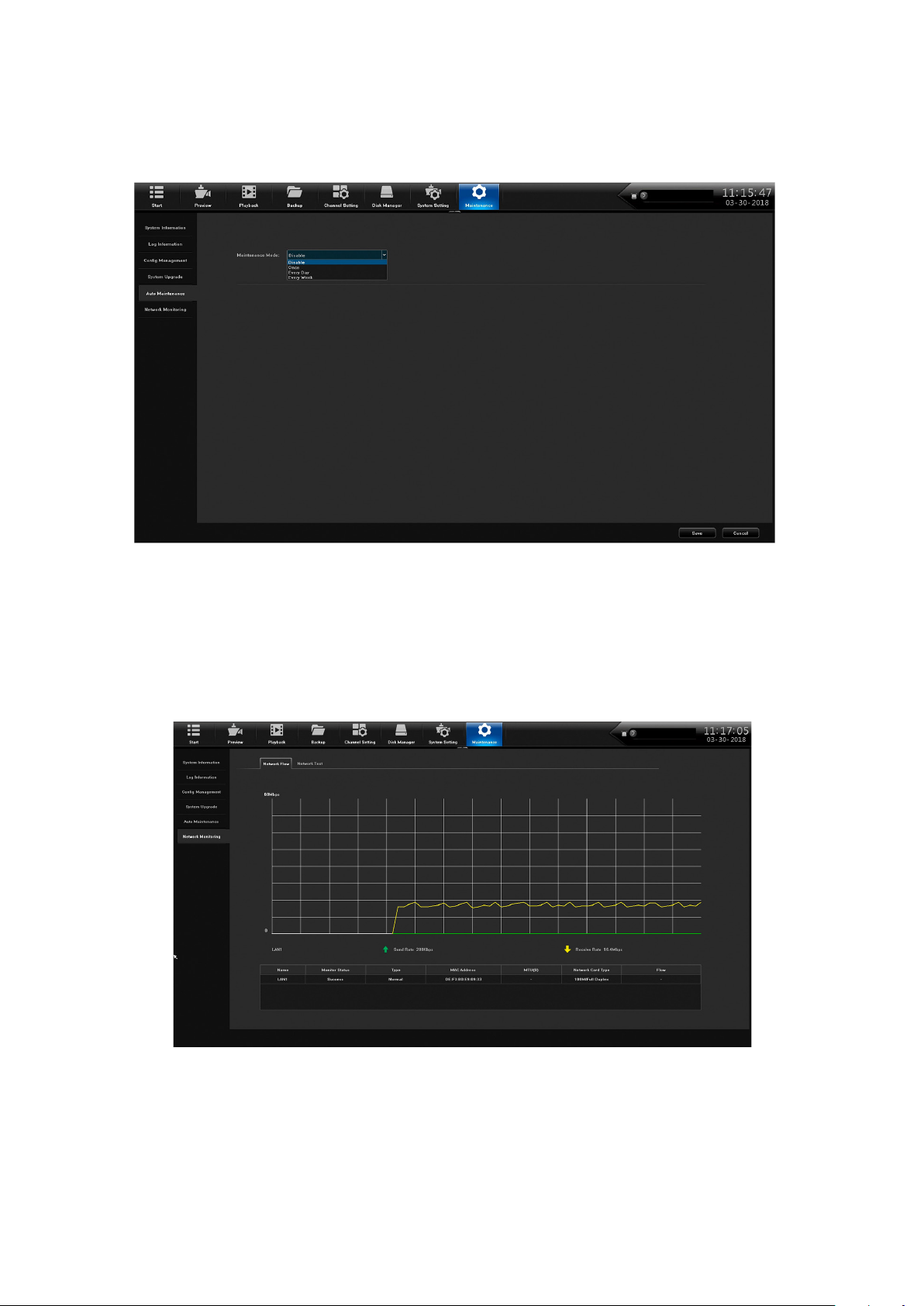
Auto Maintenance Side Tab
Maintenance mode reboots the NVR system acording to a schedule selected from the dropdown
menu..
Network Monitoring Side Tab
Network Flow Top Tab
Selecting this top tab displays a graph of network bandwidth usage in real time.
Network Test
Use this top tab to test for local network connectivity with a destination IP address. This test is
similar to a ping function.
42
Page 43

43
Page 44

FIRMWARE UPDATES
From time to time, Uniden may update its products' rmware to improve features, x bugs, or
otherwise improve the product. Uniden recommends checking for rmware updates periodically.
Check for rmware updates if you have service issues; your rmware may be out of
date.
1. Go to Main Menu/Information/System to locate the current NVR rmware version.
2. Go to http://unidensupport.com/Find-Your-Product/Downloads and look for the NVR. Check
your NVR’s rmware number against the latest rmware download available.
3. If there is a rmware version that is later than the rmware version on your system, download it
to your USB drive.
4. Power down your NVR.
5. Insert the USB drive into the non-mouse USB port on the BACK of the receiver.
Do NOT insert the USB drive into the USB port on the front of the receiver.
6. Power up your NVR. The system reboots and imports the new rmware.
44
Page 45

TROUBLESHOOTING
After turning on, the system cannot switch on normally.
Possible reasons:
• The power supply is damaged.
• Power cable is damaged.
• Firmware is outdated.
• The hard disk is damaged.
• The internal power board is damaged.
The NVR reboots automatically or frequently stops working after booting up for a few minutes
Possible reasons:
• A Network Test has been set up.
• The input voltage is not stable or too low.
• The hard disk or the hard disk cables are damaged.
• The front-end video signal is not stable.
• Poor heat dissipation, too much dust, bad physical environment for the NVR.
• NVR hardware is damaged.
Cannot detect hard disk after turning on power.
Possible reasons:
• The hard disk power supply cable is not connected.
• The hard disk cables are damaged.
• The hard disk is damaged.
• The hard disk has failed.
• The SATA port of the main board is damaged.
No video output in single channel, multiple channels, or all channels.
Possible reasons:
• Firmware is out of date. Upgrade the rmware.
• The image brightness is all 0. Please restore the default setup.
• There is no video input signal or the signal is too weak.
• The NVR hardware is damaged.
• Camera power supply damaged or unplugged.
Real-time image problems such as serious distortion of the image, color, or brightness, etc.
Possible reasons:
• The NVR is not matched with the impedance of the monitor.
• The video transmission distance is too far or the attenuation of video transmission cable is too
big.
Cannot find video files in local playback.
Possible reasons:
• The hard disk is damaged or no video data.
• Upgrade rmware which is different from the original rmware les.
• The video les you want to see are overwritten.
Local Video appears blurred.
Possible reasons:
45
Page 46

• The video quality is set too low.
• The program data reads incorrectly; reboot the NVR.
• The hard disk is damaged.
• The NVR hardware is damaged.
No audio signal in the surveillance window.
Possible reasons:
• Camera does not support audio.
• Camera’s audio is damaged.
• The NVR hardware is damaged.
There is audio signal in the surveillance window but no audio signal when playback
Possible reasons:
• The audio option is not selected.
• The corresponding channel is not connected with the video. When the image appears as a blue
screen, the playback will be intermittent.
The time display is wrong.
Possible reasons:
• The setting is wrong.
• Internal batteries are not properly connected or the voltage is too low.
NVR can not control the PTZ.
Possible reasons:
• The PTZ camera is not connected correctly.
• The baud rate, address, and protocol settings of the front-end PTZ and device PTZ are
inconsistent.
Motion detection is not working.
Possible reasons:
• Time is not set correctly.
• The motion detection area is not set correctly.
• The sensitivity is too low.
No image or poor quality video when in Live view or when playing back recorded files.
Possible reasons:
• Too much data is owing on the network (too many users logged into the system).
• Camera not connected properly (not transmitting data correctly).
• Connection issues between camera and NVR.
Something wrong with the USB backup.
Possible reasons:
• There are not enough NVR resources available. Please stop recording and proceed with backup.
• The backup device is not compatible.
• The backup device is damaged.
• Not enough room on backup device.
Alarm is not working.
Possible reasons:
• The alarm setting is incorrect.
• The alarm input signal is incorrect.
46
Page 47

SPECIFICATIONS
GENERAL
Power Supply DC48V/3A (power plug
Power Consumption <10W (Without HDD) <10W (Without HDD) <35W (Without HDD)
Operation Temperature 14°F ~ 131°F (-10°C ~
Humidity 90% 90% 90%
PRO800N2-4K PRO1600N2-4K PRO3600N2-4K
specication optional)
55°C)
DC48V/3A (power plug
specication optional
14°F ~ 131°F (-10°C ~
55°C)
AC100~240V, 50Hz~60Hz
(Power plug specication
optional)
14°F ~ 131°F (-10°C ~
55°C)
VIDEO
Network Video Input 8 CH 16 CH 36 CH
Network Access Banddepth 80Mbps 80Mbps 288Mbps
Video Compression H.265 /H.264 /MJPEG H.265 /H.264 /MJPEG H.265 /H.264 /MJPEG
HDMI Output HDMI Output 1 CH VGA output
(1920×1080@60Hz,
1280×1024@60Hz)
Video Output
Image Display 1/4/6/8/9 image display 1/4/6/8/9 image display 1/4/6/8/9/16/25/36 image
Snapshot Mode Support timing snapshot,
Motion Detection Support 396(22*18)
Privacy Mask 4 zones 4 zones 4 zones
3840×2160@30HZ,1920×
1080@60HZ,1280×1024@
60HZ
manual snapshot, JPEG
format
surveyed area can be set
in every screen and multilevel sensitivity adjustable
3840×2160@30HZ,1920×
1080@60HZ,1280×1024@
60HZ
Support timing snapshot,
manual snapshot, JPEG
format
Support 396(22*18)
surveyed area can be set
in every screen and multilevel sensitivity adjustable
1 CH HDMI output
(3840×2160@30Hz,
1920×1080@60Hz,
1280×1024 @60Hz)
display
Support timing snapshot,
manual snapshot, JPEG
format
Support 396(22*18)
surveyed area can be set
in every screen and multilevel sensitivity adjustable
VIDEO RECORDING AND PLAYBACK
Frame Rate 1-30fps 1-30fps 1-30fps
Record Mode Manual/external alarm/ MD/
timing/intelligent analysis
alarm
Playback Mode Instant playback, Local
video, local image, External
le playback
Manual/external alarm/ MD/
timing/intelligent analysis
alarm
Instant playback, Local
video, local image, External
le playback
Manual/external alarm/ MD/
timing/intelligent analysis
alarm
Instant playback, Local
video, local image, External
le playback
AUDIO
Audio Compression G.711u G.711u G.711u
Audio Input IPC complex audio input IPC complex audio input 1 CH RCA port (IPC
complex audio input)
Audio Output 1CH, RCA interface 1CH, RCA interface 1CH, RCA port
Bidirectional Talk Input NA NA Bidrection talk, RCA port
STORAGE AND BACKUP
Storage Interface 2 SATA 2 SATA 8 SATA, 1 E-SATA
HDD Capacity Single max. 8TB Single max. 8TB Single max. 8TB
Backup Location Local, network Local, network Local, network, NAS,
IPSAN
Array Type NA NA Raid0, Raid1, Raid5,
Raid6, Raid10
Backup Method USB mobile hard disk, U
disk, network backup
USB mobile hard disk, U
disk, network backup
USB mobile hard disk, U
disk, network backup
47
Page 48

GENERAL
ANR Support FSAN IPC (with TF
PRO800N2-4K PRO1600N2-4K PRO3600N2-4K
card) ANR
Support FSAN IPC (with TF
card) ANR
Support FSAN IPC (with TF
card) ANR
EXT. INTERFACE
Network Interface 1 RJ45 100M Ethernet port 1 RJ45 100M Ethernet port 1 RJ45 100M1000M
adaptive Ethernet port
PoE Interface 8CH (IEEE 802.3af) 8CH (IEEE 802.3af) 16CH
Alarm Input 0 4 CH 4 CH
Alarms Output 1 CH 1 CH 1 CH
RS485 1CH 1CH 1CH
USB Interface Rear panel: 2 USB 2.0 Rear panel: 2 USB 2.0 Front panel: 1 USB 2.0
Rear panel: 1 USB 2.0, 1
USB 3.0
GENERAL
Power Supply DC48V/3A (power plug
Power Consumption <10W (Without HDD) <10W (Without HDD) <35W (Without HDD)
Operation Temperature 14°F ~ 131°F (-10°C ~
Humidity 90% 90% 90%
PRO3600N8-4K PRO6400N0-4K PRO12800N0-4K
specication optional)
55°C)
DC48V/3A (power plug
specication optional
14°F ~ 131°F (-10°C ~
55°C)
AC100~240V, 50Hz~60Hz
(Power plug specication
optional)
14°F ~ 131°F (-10°C ~
55°C)
VIDEO
Network Video Input 36 CH 64 CH 128 CH
Network Access Banddepth 288Mbps 512Mbps 640Mbps
Video Compression H.265 /H.264 /MJPEG H.265 /H.264 /MJPEG H.265 /H.264 /MJPEG
1 CH VGA output
(1920×1080@60Hz
1280×1024@60Hz)
Video Output
Image Display 1/4/6/8/9 image display 1/4/6/8/9/16/25/36/64
Snapshot Mode Support timing snapshot,
Motion Detection Support 396 (22*18)
Privacy Mask 4 zones 4 zones 4 zones
1 CH HDMI output
(3840×2160@30Hz,
1920×1080@60Hz,
1280×1024 @60Hz)
manual snapshot, JPEG
format
surveyed area can be set
in every screen and multilevel sensitivity adjustable
1 CH VGA output
(1920×1080@60Hz
1280×1024@60Hz)
1 CH HDMI output
(3840×2160@30Hz,
1920×1080@60Hz,
1280×1024 @60Hz)
image display
Support timing snapshot,
manual snapshot, JPEG
format
Support 396 (22*18)
surveyed area can be set
in every screen and multilevel sensitivity adjustable
2CH VGA Heterologous
output (1920×1080@60Hz,
1280×1024@60Hz)
2CH HDMI Heterologous
output
(3840×2160@30Hz,
1920×1080@60Hz,
1280×1024@60Hz)
1/4/6/8/9/16/25/36/64
image display
Support timing snapshot,
manual snapshot, JPEG
format
Support 396 (22*18)
surveyed area can be set
in every screen and multilevel sensitivity adjustable
VIDEO RECORDING AND PLAYBACK
Frame Rate 1-30fps 1-30fps 1-30fps
Record Mode Manual/external alarm/ MD/
timing/intelligent analysis
alarm
Playback Mode Instant playback, Local
video, local image, External
le playback
Manual/external alarm/ MD/
timing/intelligent analysis
alarm
Instant playback, Local
video, local image, External
le playback
Manual/external alarm/ MD/
timing/intelligent analysis
alarm
Instant playback, Local
video, local image, External
le playback
AUDIO
Audio Compression G.711u G.711u G.711u
48
Page 49

GENERAL
Audio Input IPC complex audio input IPC complex audio input 1 CH RCA port (IPC
Audio Output 1CH, RCA port 1CH, RCA port 2CH, RCA interface
Bidirectional Talk Input Bidrection talk, RCA port Bidrection talk, RCA port Bidrection talk, RCA port
PRO3600N8-4K PRO6400N0-4K PRO12800N0-4K
complex audio input)
STORAGE AND BACKUP
Storage Interface 8 SATA, 1 E-SATA 8 SATA, 1 E-SATA 16 SATA, 2 E-SATA
HDD Capacity Single max. 8TB Single max. 8TB Single max. 8TB
Backup Location Local, network, NAS,
IPSAN
Array Type Raid0, Raid1, Raid5,
Raid6, Raid10
Backup Method USB mobile hard disk, U
disk, network backup
ANR Support FSAN IPC (with
SD card) ANR
Local, network, NAS,
IPSAN
Raid0, Raid1, Raid5,
Raid6, Raid10
USB mobile hard disk, U
disk, network backup
Support FSAN IPC (with
SD card) ANR
Local, network, NAS,
IPSAN
Raid0, Raid1, Raid5,
Raid6, Raid10
USB mobile hard disk, U
disk, network backup
Support FSAN IPC (with
SD card) ANR
EXT. INTERFACE
Network Interface 1 RJ45 100M/1000M
Ethernet port
PoE Interface 16CH NA NA
Alarm Input 4 Ch 16 CH 16 Ch
Alarms Output 1 CH 4 CH 8 CH
RS485 1CH 1CH RS422: 1CH
USB Interface Front panel: 1 USB 2.0,
Rear panel: 1 USB 2.0, 1
USB 3.0
2 RJ45 100M/1000M
adaptive Ethernet port
Front panel: 1 USB 2.0,
Rear panel: 1 USB 2.0, 1
USB 3.0
1 RJ45 100M/1000M
adaptive Ethernet port
Front panel: 2 USB2.0
Rear panel: 1 USB3.0
GENERAL
Power Supply DC48V/3A (power plug specication optional) DC48V/3A (power plug specication
Power Consumption <10W (Without HDD) <10W (Without HDD)
Operation Temperature 14°F ~ 131°F (-10°C ~ 55°C) 14°F ~ 131°F (-10°C ~ 55°C)
Humidity 90% 90%
PRO800N2-5MP PRO1600N3-5MP
optional
VIDEO
Network Video Input 8 CH 16 CH
Network Access Banddepth 60 Mbps 80 Mbps
Video Compression H.264 /MJPEG H.265 /H.264 /MJPEG
Video Output
Image Display 1/4/6/8/9 image display 1/4/6/8/9/16 image display
Snapshot Mode Support timing snapshot, manual snapshot,
Motion Detection Support 396 (22*18) surveyed area can be
Privacy Mask 4 zones 4 zones
VGA/HDMI sync output VGA/HDMI sync output
1920×1080@60Hz 1280×1024@60Hz 1920×1080@60Hz 1280×1024@60Hz
Support timing snapshot, manual
JPEG format
set in every screen and multi-level sensitivity
adjustable
snapshot, JPEG format
Support 396 (22*18) surveyed area can
be set in every screen and multi-level
sensitivity adjustable
VIDEO RECORDING AND PLAYBACK
Frame Rate 1-30fps 1-30fps
Record Mode Manual/external alarm/ MD/timing/intelligent
analysis alarm
Playback Mode Instant playback, local video, local image,
external le playback
Manual/external alarm/ MD/timing/
intelligent analysis alarm
Instant playback, local video, local
image, external le playback
49
Page 50

GENERAL
PRO800N2-5MP PRO1600N3-5MP
AUDIO
Audio Compression G.711u G.711u
Audio Input IPC complex audio input IPC complex audio input
Audio Output NA NA
Bidirectional Talk Input NA NA
STORAGE AND BACKUP
Storage Interface 1 SATA 2 SATA
HDD Capacity Single max. 8TB Single max. 8TB
Backup Location Local, network, IPSAN Local, network, IPSAN
Array Type NA Raid0, Raid1, Raid5, Raid6, Raid10
Backup Method USB mobile hard disk, U disk, network
backup
ANR Support FSAN IPC (with SD card) ANR Support FSAN IPC (with SD card) ANR
USB mobile hard disk, U disk, network
backup
EXT. INTERFACE
Network Interface 1 RJ45 100M adaptive Ethernet port 1 RJ45 100M /1000M adaptive
Ethernet port
PoE Interface 8CH (IEEE 802.3af) 8CH (IEEE 802.3af)
Alarm Input 2CH 4 CH
Alarms Output 1 CH 1 CH
RS485 1CH 1CH
USB Interface Front panel: 1 USB 2.0
Rear panel: 1 USB 2.0
Front panel: 1 USB 2.0
Rear panel: 1 USB 2.0
Recycling and Disposal Information
• Do not dispose of electronic devices or any of their components (especially batteries and LCD displays)
in your municipal trash collection.
• Consult your local waste management authority or a recycling organization like Earth911.com to nd an
electronics recycling facility in your area.
FCC Part 15/IC COMPLIANCE
FCC Compliance
This device complies with Part 15 of the FCC rules. Operation is subject to the following two
conditions: (1) This device may not cause harmful interference, and (2) this device must accept
any interference received, including interference that may cause undesired operation.
Changes or modications not expressly approved by the party responsible for compliance could
void your authority to operate the equipment.
Avis de conformité à la FCC : Ce dispositif a été testé et s’avère conforme à l’article 15 des
règlements de la Commission fédérale des communications (FCC). Ce dispositif est soumis
aux conditions suivantes: 1) Ce dispositif ne doit pas causer d’interférences nuisibles et; 2)
Il doit pouvoir supporter les parasites qu’il reçoit, incluant les parasites pouvant nuire à son
fonctionnement.
Tout changement ou modication non approuvé expressément par la partie responsable pourrait
annuler le droit à l’utilisateur de faire fonctionner cet équipement.
50
Page 51

IC Compliance
This device complies with Industry Canada license-exempt RSS standard(s). Operation is subject
to the following two conditions: (1) this device may not cause interference, and (2) this device must
accept any interference, including interference that may cause undesired operation of the device.
Changes or modications not expressly approved by the party responsible for compliance could
void your authority to operate the equipment.
Cet appareil est conforme aux normes RSS exemptes de licences d’Industrie Canada. Son
fonctionnement est soumis aux deux conditions suivantes : (1) cet appareil ne doit pas causer
d’interférences nuisibles et (2), il doit pouvoir accepter les interférences, incluant celles pouvant
nuire à son fonctionnement normal.
Tout changement ou modication non approuvé expressément par la partie responsable pourrait
annuler le droit à l’utilisateur de faire fonctionner cet équipement.
THREE-YEAR LIMITED WARRANTY
Important: SAVE YOUR RECEIPT! Evidence of original purchase is required for warranty service.
WARRANTOR: Uniden America Corporation (“Uniden”) ELEMENTS OF WARRANTY: Uniden warrants,
for three years, to the original retail owner, this Uniden Product to be free from defects in materials &
craftsmanship with only the limitations or exclusions set out below.
WARRANTY DURATION: This warranty to the original user shall terminate & be of no further effect 36
months after the date of original retail sale. The warranty is invalid if the Product is (A) damaged or not
maintained as reasonable or necessary, (B) modied, altered, or used as part of any conversion kits,
subassemblies, or any congurations not sold by Uniden, (C) improperly installed, (D) serviced or repaired
by someone other than an authorized Uniden service center for a defect or malfunction covered by this
warranty, (E) used in any conjunction with equipment or parts or as part of any system not manufactured
by Uniden, or (F) installed or programmed by anyone other than as detailed by the owner’s manual for this
product.
STATEMENT OF REMEDY: In the event that the product does not conform to this warranty at any time
while this warranty is in effect, warrantor will either, at its option, repair or replace the defective unit &
return it to you without charge for parts, service, or any other cost (except shipping & handling) incurred by
warrantor or its representatives in connection with the performance of this warranty. Warrantor, at its option,
may replace the unit with a new or refurbished unit.
THE LIMITED WARRANTY SET FORTH ABOVE IS THE SOLE & ENTIRE WARRANTY PERTAINING
TO THE PRODUCT & IS IN LIEU OF & EXCLUDES ALL OTHER WARRANTIES OF ANY NATURE
WHATSOEVER, WHETHER EXPRESS, IMPLIED OR ARISING BY OPERATION OF LAW, INCLUDING,
BUT NOT LIMITED TO ANY IMPLIED WARRANTIES OF MERCHANTABILITY OR FITNESS FOR
A PARTICULAR PURPOSE. THIS WARRANTY DOES NOT COVER OR PROVIDE FOR THE
REIMBURSEMENT OR PAYMENT OF INCIDENTAL OR CONSEQUENTIAL DAMAGES. Some states
do not allow this exclusion or limitation of incidental or consequential damages so the above limitation or
exclusion may not apply to you.
LEGAL REMEDIES: This warranty gives you specic legal rights, & you may also have other rights which
vary from state to state. This warranty is void outside the United States of America & Canada.
PROCEDURE FOR OBTAINING PERFORMANCE OF WARRANTY: If, after following the instructions in
the owner’s manual you are certain that the Product is defective, pack the Product carefully (preferably
in its original packaging). The Product should include all parts & accessories originally packaged with the
Product. Include evidence of original purchase & a note describing the defect that has caused you to return
it. The Product should be shipped freight prepaid, by traceable means, to warrantor at:
Uniden America Service
C/O Saddle Creek
743 Henrietta Creek Rd., Suite 100
Roanoke, TX 76026
51
Page 52

 Loading...