

Page 1

Introduction
Welcome to the world of CB radio communication. Your Uniden
represents the most advanced portable radio ever designed for use in the
Citizens Band Radio Service. This powerful unit operates on any of the 40 AM
frequencies authorized by the Federal Communications Commission (FCC).
Among its many features, the
•
Superheterodyne circuitry
•
Phase Locked Loop Synthesizer
frequency control.
• Flexible operation that allows you to power the radio with 8 AA alkaline
batteries, 10 rechargeable AA nickel-cadmium batteries (batteries not
included), or from your vehicle battery.
• Connection for an optional nickel-cadmium battery charger.
This radio has been type accepted and fully certified by the FCC.
PRO340XL
includes:
to enhance receiver quality.
techniques to assure precise
PRO340XL
WARNING
The Citizens Band (CB) Radio Service is under the jurisdiction of the
Federal Communications Commission (FCC). Any adjustments or
alterations which alter the performance of the transceiver’s original FCC
type acceptance, or change the frequency determining method, are
strictly prohibited. Replacement or substitution of crystals, transistors,
ICs regulator diodes, or any other part of a unique nature, with parts other
than those recommended by Uniden may cause violations of the technical
regulations of Part 95 of the FCC rules or violation as type acceptance
requirements of Part 2 of the rules.
Elimination Of Licensing
The Federal Communications Commission has ruled that Citizens Band Radio
Service operators are no longer required to obtain an FCC license to operate
their CB equipment. In doing so, the FCC also permits CB stations to operate
without station identification.
Elimination of individual station licenses results in no lessening of the operating
privileges or responsibilities of CB users. An operator of a CB radio station is
still required to comply with the Communications Act and with the rules of CB
Radio Service.
1
Page 2

Unpacking Your CB Radio
Carefully unpack your
•
PRO340XL
• 2 Battery Spacers (For use with alkaline batteries)
• Cigarette Lighter Power Cord
• Flexible Antenna
• Belt Clip (Attached to radio)
• This Operating Guide (Read it carefully and save)
• Part 95 Subpart D (FCC Rules)
• Product Registration Card (In Operating Guide)
PRO340XL
and check the contents against this list:
Portable CB Radio
If any items are missing or damaged, contact your place of purchase
immediately.
Be sure to complete and mail in the Product Registration Card.
WARNING
Do not attempt to charge alkaline batteries in this radio. Make sure
you have installed 10 recharge able nicke l-cad miu m batt eri e s bef ore
connecting power to the charge connection.
For optimum performance, use only Alkaline AA or Nickel-Cadmium AA
batteries in this unit. See pages 5 through 7 for directions for inserting batteries.
2
Page 3

Controls And Functions
TX Indicator
BATT LOW LED
Channel Display
HI/LOW Switch
ON/OFF Switch
Channel Selector
SQUELCH Control
VOLUME Control
Microphone
Speaker
— LED lights to indicate when the radio is transmitting.
— Lights when the batteries become weak and need to be
— Turns the radio on and off.
— Transforms speech into transmission signals.
— Produces audible signals from incoming transmissions.
Front View
replaced.
— A large LED display shows the current channel in use.
— Changes transmitter power from low to high.
— Selects any of the 40 CB channels.
— Adjusts the squelch level.
— Adjusts the volume level.
3
Page 4
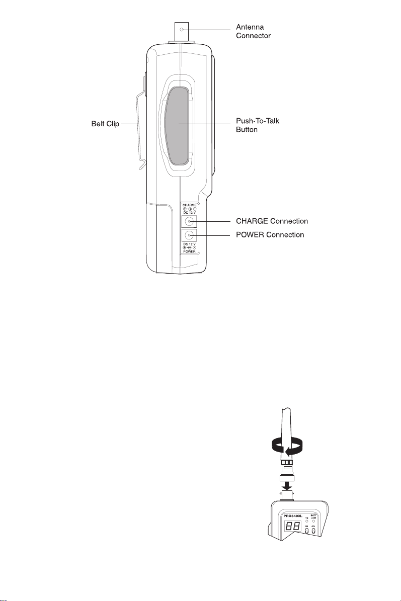
Side View
Antenna Connector —
Belt Clip —
Push-to-Talk But to n —
CHARGE Connection —
POWER Connection —
Provides a connection for the supplied flexible antenna.
Connects to belt for portability.
Switches the CB from receive to transmit mode.
Connection for a 12V DC power source to charge
nickel-cadmium batteries while installed in the radio.
Connection for a 12V DC external power source.
Connecting the Antenna
1. Align the two keys on the
connector with the key slots in the base of
the flexible antenna.
2. Push the base of the flexible antenna down
onto the antenna connector.
3. Twist the base clockwise to lock the antenna
in place.
PRO340XL
antenna
4
Page 5
Power
The
PRO340XL
be supplied thro ug h 10 AA, 1 .2 volt, r echa r ge able nicke l- cadmiu m ba tt erie s; 8 AA,
1.5 volt alkaline batteries; or through the supplied cigarette lighter power cord when
connected to a ve hicle ’s 1 2 volt n egat ive gro und po wer syst em .
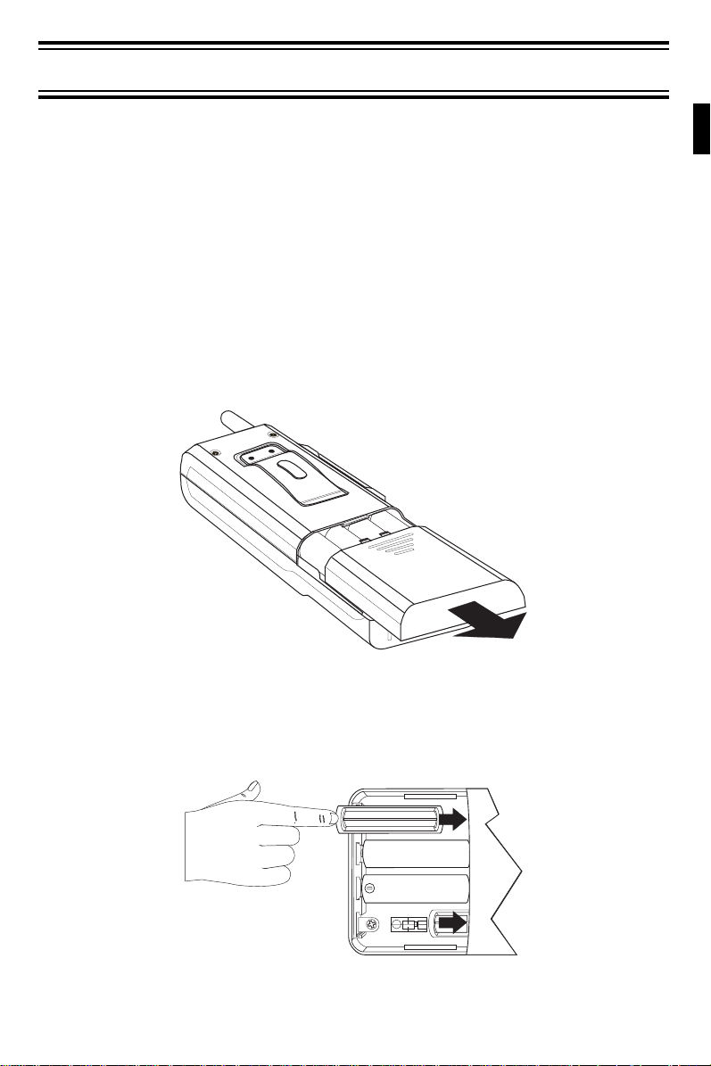
Installing Batteries
WARNING: Do not mix alkaline batteries with nickel-cadmium batteries.
Alkaline Batteries
Note:
is designed to operate with ma ximum 12 volt DC power. Power can
To insure circuit continuity, use the two battery spacers supplied.
1. Slide the cover off the back of the
2. Insert the battery spacers in the positions shown. They should go all the
way into the case.
PRO340XL
.
-
5
Page 6
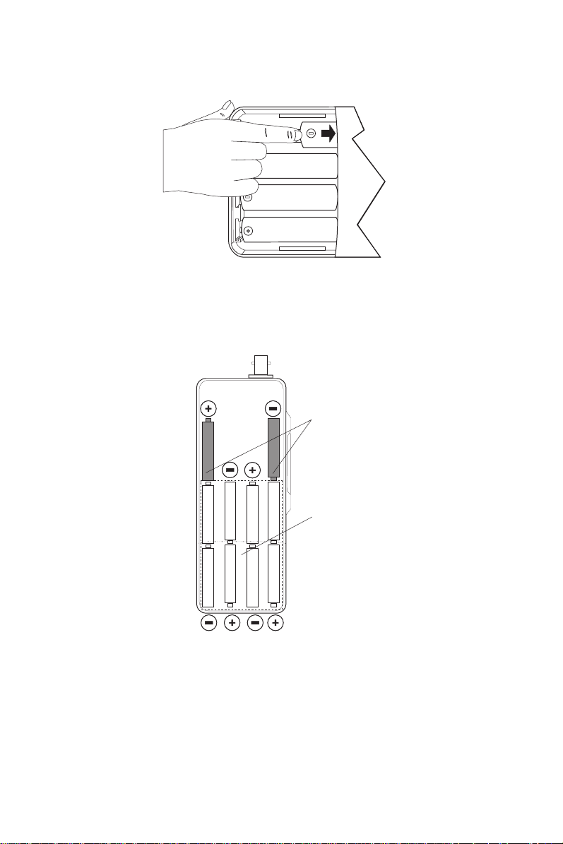
3. Insert 8 alkaline batteries into the compartment as shown.
-
Be sure to insert each battery with the proper polarity, as marked in
Note:
the battery compartment.
Follow this diagram for correct alkaline battery placement.
(2)
Battery
Spacers
4. Replace the cover.
Note:
When the batteries become weak, the BATT LOW LED will light.
Be sure to replace the batteries as soon as possible. You can
preserve battery power by selecting the “LOW” position on the
HI/LOW switch. The “LOW” setting has a substantially shorter
transmission range. (See the Operation section.)
6
(8)
1.5 V Alkaline
Batteries
Page 7

Nickel-Cadmium Batteries.
1. Slide the cover off the back of the
2. Insert 10 nickel cadmium batteries in the compartment.
Be sure to insert each battery with the proper polarity, as marked in
Note:
PRO340XL
.
the battery compartment.
Note:
The battery spacers are NOT used when installing nickel-cadmium
batteries.
Follow this diagram for correct nickel-cadmium battery placement.
Nickel-cadmium battery placement
3. Replace the cover.
Note:
When the batteries become weak, the BATT LOW LED will light.
Be sure to replace the batteries as soon as possible. You can
preserve battery power by selecting the “LOW” position on the
HI/LOW switch. The “LOW” setting has a substantially shorter
transmission range. (See the Operation section.)
7
Page 8

Connecting the Cigarette Lighter Power Cord
Using the Cigarette Lighter Power Cord whenever you are operating the
PRO340XL
in a vehicle saves the radio’s internal battery life.
IMPORTANT:
The Cigarette Lighter Power Cord is designed to be used
with
ONLY
negative
ground vehicles.
Do not
operate the unit with the power cord connected to a positive
ground vehicle.
To connect the Cigarette Lighter Power Cord:
1. Connect the power cord to the
radio.
2. Plug the power cord into the cigarette lighter of your vehicle.
Note:
Power is disconnected from the radio’s battery compartment when
POWER
connection on the side of the
using the cigarette lighter power cord.
attempt to
8
Page 9

Operation
Before operating the
1. Be sure you read and understand Part 95 of the FCC Rules and
Regulations.
2. Be sure that the power source and antenna are properly connected.
3. Turn the unit on by sliding the power switch up to the ON position.
PRO340XL:
Receive
1. Use the
once to change one channel at a time. Press and hold to rapidly change
channels.
2. Set the
3. Adjust the
absence of a signal. Move
disappears (no signal should be present). Leave the control at this
setting. The receiver will remain quiet until a signal is actually received.
Note:
Up/Down
VOLUME
Do not advance the control too far, or some weaker signals will not
be heard.
channel keys to select any of the 40 channels. Press
control to a comfortable listening level.
SQUELCH
control to eliminate background noise during the
SQUELCH
to the right
until the noise
Transmit
1. Set the
• In the “HI” (4 watt) position, the unit transmits at maximum output power
• In the “LOW” (1 watt) position, transmission output power (range) is
HI/LOW
Switch.
and achieves maximum range.
substantially reduced; but, the battery life will be increased.
For maximum battery life
not affect the reception range.
,
select the “LOW” position. This switch does
2. If the channel is clear, press the
Be sure to speak clearly into the microphone.
IMPORTANT:
communication. Channel 9 is reserved by the FCC for emergency
communications involving the immediate safety of individuals or the
protection of property. Channel 9 may also be used to render assistance
to a motorist.
radios.
All channels, except channel 9, may be used for normal
This is an FCC rule and applies to all operators of CB
Push-To-Talk But ton
9
on the side of the unit.
Page 10

Care and Maintena nce
The
PRO340XL
no user-serviceable parts inside and except for the batteries, or the fuse inside
the cigarette lighter plug, no maintenance is required.
Note:
Replacing the Cigarette Lighter Plug Fuse
The cigarette lighter plug contains a 2-ampere fuse to protect it from power surges.
To replace a blown fuse:
1. Squeeze the two metal contacts on the cigarette lighter plug cap and
unscrew the cap counterclockwise.
is designed to give you years of trouble-free service. There are
Do not expose the unit to moisture. Rain, dew, road splash, or
other liquids may damage the internal components.
2. Remove the fuse and replace it with the same type.
3. Replace the cap by grasping the plug’s two metal contacts and squeezing
them while twisting the cap back on. Make sure the cap is tightly secured.
Replacing the Batteries
See “Installing Batteries.”
10
Page 11

Recharging Batteries
You can recharge nickel-cadmium batteries while they are installed in the
PRO340XL
Adapter (AD140U). Be sure to observe the polarity of the Adapter before
connecting it to the radio.
Using the Cigarette Lighter Power Cord
. Use the included Cigarette Lighter Power Cord or an optional AC
Note:
The
PRO340XL
Do not attempt to charge alkaline batteries in this radio. Make sure you
have installed 10 rechargeable nickel-cadmium batteries before
connecting power to the charge connection.
IMPORTANT:
will not operate while the batteries are recharging.
WARNING
The Cigarette Lighter Power Cord is designed to be used
ONLY
with
negative
ground vehicles.
Do not
attempt to
charge the batteries with the power cord connected to a
positive ground vehicle.
1. Plug one end of the Cigarette Lighter Power Cord into the
connection on the side of the
2. Plug the other end of the Cigarette Lighter Power Cord into the vehicle’s
cigarette lighter socket.
Using an optional AC Adapter
IMPORTANT:
1. Plug one end of the AC Adapter into the
of the
PRO340XL
2. Connect the other end of the AC Adapter to an AC power source.
Note:
Typical charging time is 12 hours.
Make sure you use only a Uniden AD140U AC Adapter.
.
PRO340XL
.
CHARGE
connection on the side
CHARGE
11
Page 12

Troubleshooting
If the
PRO340XL
troubleshooting suggestions listed below. If you cannot get satisfactory results,
call the Uniden Customer Service Center at:
does not perform to your expectations, please try the
1-800-297-1023,
8:00 a.m. to 5:00 p.m. Central, Monday through Friday.
Problem
Unit does not power on.
•• Check the battery connections.
•• Check for weak or dead batteries.
•• If you are using the cigarette lighter power
Suggestion
cord, check all connections as well as the
fuse inside the cigarette lighter plug. Also
check the vehicle electrical system.
Poor reception.
Weak Transmission.
•• Check and adjust the SQUELCH.
•• Check the antenna connections.
•• Check for weak batteries.
•• Check the antenna connections.
•• Check the HI-LOW switch.
•• Check for weak batteries.
Servicing Your CB
If service is necessary, contact your local Uniden dealer or return the product in
its original carton. If you are shipping the item, enclose a brief description of
the problem along with a copy of the original purchase receipt. Send the
product to the address listed in the Warranty (at the end of this manual).
Technical information, diagrams, and charts are available upon request. It is
the user’s responsibility to see that this radio is operating at all times in
accordance with the FCC Citizens Band Radio Service regulations. We highly
recommend that you consult a qualified radiotelephone technician for service
and alignment of this radio.
When ordering parts, please specify the correct model number and serial
number of this radio.
Please refer to the “WARNING” information at the front of this manual.
12
Page 13

Specifications
Channels: 40 AM
Frequency Range: 26.965 to 27.405 MHz
Frequency Control: Phase Locked Loop (PLL) synthesizer
Frequency Tolerance: ± 0.005%
Operating Temperature: -22
Microphone: Electret type (Built-in)
Input Voltage: 12.0 VDC nominal (negative ground)
Current Drain: TX: Full modulation, 1.4A
Size: 2-
Complete Package: 1 lb. 5 oz.
Antenna Connector: BNC
Transmitter
Power Output: Selectable 1 watt or 4 watts
Modulation: Class B amplitude modulation
Frequency Response: 300 to 3000 Hz
Output Impedance: 50Ω unbalanced
°
F to +122° F
RX: With maximum audio output, 0.5A
5
⁄8“ (W) x 1-1⁄2” (D) x 5-1⁄2“ (H)
Receiver
Sensitivity: 0.7 µV for 10 dB; (S+N)/N typical
Selectivity: 6 dB @ 7 kHz, 70 dB @ 10 kHz typical
Image Rejection: 75 dB typical
IF Frequency: Double Conversion Superheterodyne
1st: 10.695 MHz
2nd: 455 kHz
Automatic Gain Control
(AGC):
Squelch: Adjustable; threshold less than 1 µV
Audio Outp ut Pow er: 0.5 watts max. into 8Ω
Frequency Response: 300 to 2500 Hz
Distortion: Less than 10% at 0.4 watts, 1000 Hz
Internal Speaker: 16Ω, 0.5 watts round
Specifications shown are typical and subject to change without notice.
Less than 10 dB change in audio output for inputs
from 10 to 50,000 µV
13
Page 14

®
PRO340XL
Citizens Band
Radio
OPERATING GUIDE
Page 15

Contents
Introduction . . . . . . . . . . . . . . . . . . . . . . . . . . . . . . . . . . . . . . . . . . . . . . . . . . 1
Elimination Of Licensing . . . . . . . . . . . . . . . . . . . . . . . . . . . . . . . . . . . . . . . 1
Unpacking Your CB Radio. . . . . . . . . . . . . . . . . . . . . . . . . . . . . . . . . . . . . . . 2
Controls And Functions . . . . . . . . . . . . . . . . . . . . . . . . . . . . . . . . . . . . . . . . 3
Connecting the Antenna. . . . . . . . . . . . . . . . . . . . . . . . . . . . . . . . . . . . . . . . 4
Power. . . . . . . . . . . . . . . . . . . . . . . . . . . . . . . . . . . . . . . . . . . . . . . . . . . . . . . . 5
Installing Batteries . . . . . . . . . . . . . . . . . . . . . . . . . . . . . . . . . . . . . . . . . . . . 5
Alkaline Batteries. . . . . . . . . . . . . . . . . . . . . . . . . . . . . . . . . . . . . . . . . . 5
Nickel-Cadmium Batteries. . . . . . . . . . . . . . . . . . . . . . . . . . . . . . . . . . . 7
Connecting the Cigarette Lighter Power Cord . . . . . . . . . . . . . . . . . . . . . . . 8
Operation . . . . . . . . . . . . . . . . . . . . . . . . . . . . . . . . . . . . . . . . . . . . . . . . . . . . 9
Before operating the
Receive . . . . . . . . . . . . . . . . . . . . . . . . . . . . . . . . . . . . . . . . . . . . . . . . . . . . 9
Transmit. . . . . . . . . . . . . . . . . . . . . . . . . . . . . . . . . . . . . . . . . . . . . . . . . . . . 9
Care and Maintenance. . . . . . . . . . . . . . . . . . . . . . . . . . . . . . . . . . . . . . . . . 10
Replacing the Cigarette Lighter Plug Fuse . . . . . . . . . . . . . . . . . . . . . . . . 10
Replacing the Batteries . . . . . . . . . . . . . . . . . . . . . . . . . . . . . . . . . . . . . . . 10
Recharging Batteries . . . . . . . . . . . . . . . . . . . . . . . . . . . . . . . . . . . . . . . . . 11
Using the Cigarette Lighter Power Cord . . . . . . . . . . . . . . . . . . . . . . . 11
Using an Optional AC Adapter . . . . . . . . . . . . . . . . . . . . . . . . . . . . . . 11
Troubleshooting . . . . . . . . . . . . . . . . . . . . . . . . . . . . . . . . . . . . . . . . . . . . . 12
Servicing Your CB . . . . . . . . . . . . . . . . . . . . . . . . . . . . . . . . . . . . . . . . . . . 12
Specifications. . . . . . . . . . . . . . . . . . . . . . . . . . . . . . . . . . . . . . . . . . . . . . . . 13
PRO340XL:
. . . . . . . . . . . . . . . . . . . . . . . . . . . . . . . . . . 9
Features, Specifications and availability of Optional Accessories are all
subject to change without notice.
Uniden® is a registered trademark of Uniden America Corporation.
Page 16

Two Year Limited Warran ty
WARRANTOR: UNIDEN MANUFACTURING, INC ("Uniden")
ELEMENTS OF WARRANTY: Uniden warrants, for two years, to the
original retail owner, this Uniden Product to be free from defects in materials
and craftsmanship with only the limitations or exclusions set out below.
WARRANTY DURATION: This warranty to the original user shall terminate
and be of no further effect 24 months after the date of original retail sale.
The warranty is invalid if the Product is (A) damaged or not maintained as
reasonable or necessary, (B) modified, altered, or used as part of any
conversion kits, subassemblies, or any configurations not sold by Uniden,
(C) improperly installed, (D) serviced or repaired by someone other than an
authorized Uniden service center for a defect or malfunction covered by this
warranty, (E) used in any conjunction with equipment or parts or as part of
any system not manufactured by Uniden, or (F) installed or programmed by
anyone other than as detailed by the Operating Guide for this product.
STATEMENT OF REMEDY: In the event that the product does not conform
to this warranty at any time while this warranty is in effect, warrantor will
repair the defect and return it to you without charge for parts, service, or any
other cost (except shipping and handling) incurred by warrantor or its
representatives in connection with the performance of this warranty. THE
LIMITED WARRANTY SET FORTH ABOVE IS THE SOLE AND ENTIRE
WARRANTY PERTAINING TO THE PRODUCT AND IS IN LIEU OF AND
EXCLUDES ALL OTHER WARRANTIES OF ANY NATURE
WHATSOEVER, WHETHER EXPRESS, IMPLIED OR ARISING BY
OPERATION OF LAW, INCLUDING, BUT NOT LIMITED TO ANY IMPLIED
WARRANTIES OF MERCHANTABILITY OR FITNESS FOR A
PARTICULAR PURPOSE. THIS WARRANTY DOES NOT COVER OR
PROVIDE FOR THE REIMBURSEMENT OR PAYMENT OF INCIDENTAL
OR CONSEQUENTIAL DAMAGES. Some states do not allow this exclusion
or limitation of incidental or consequential damages so the above limitation
or exclusion may not apply to you.
LEGAL REMEDIES: This warranty gives you specific legal rights, and you
may also have other rights which vary from state to state. This warranty is
void outside the United States of America.
PROCEDURE FOR OBTAINING PERFORMANCE OF WARRANTY: If,
after following the instructions in this Operating Guide you are certain that
the Product is defective, pack the Product carefully (preferably in its original
packaging). Include evidence of original purchase and a note describing the
defect that has caused you to return it. The Product should be shipped
freight prepaid by traceable means, or delivered, to warrantor at:
Uniden America Corporation
Parts and Service
4700 Amon Carter Blvd.
Ft. Worth, TX 76155
(800) 297-1023, 8 AM to 5 PM Central, Monday through Friday
Page 17

®
©1994 Uniden America Corporation. All rights reserved.
UTUD01347ZZ Printed in the Philippines
 Loading...