

Uniden GNC 701, GNC 710 Quick Start Manual
1
Quick-Start Guide
GNC 701/710
IP Camera
Use this Quick-Start Guide to connect the camera to the network
and for basic installation and setup procedure. For more detailed
instructions refer to the online Owner’s Manual on the Uniden
website www.uniden.com.au. This quick start guide is for reference
only. Slight difference may be found in user interface.
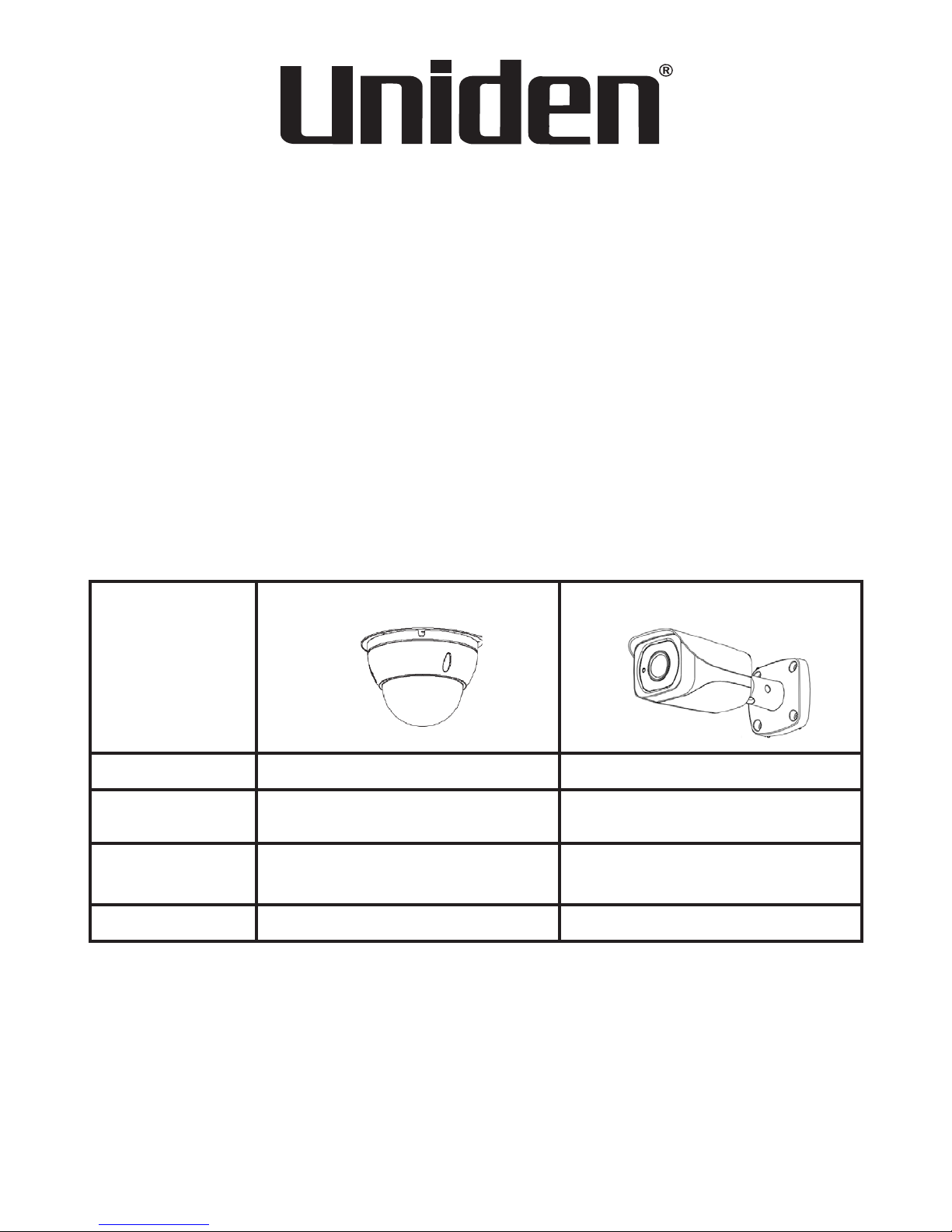
In the Box
Model GNC701 GNC710
QSG 1 1
Mounting Screw
Kit
1 1
Installation
Position Map
1 1
Hex wrench 1 -
If any item is missing or damaged, contact your place of purchase
immediately. Never use damaged products!
Need help? Get answers at our website:
www.uniden.com.au for Australian model

2
1. Do not drop, puncture or disassemble the camera.
2. DO NOT expose the camera to excessive water or moisture.
3. Never tug on the power cable to unplug from the power outlet. Always
grasp the AC adapter when unplugging.
4. Do not expose the camera to high temperature or leave it in direct
sunlight. Doing so may damage the camera or cause camera
temporary malfunction.
5. For your own safety, avoid using the camera or power off the camera
when there is a storm or lightning.
6. Remove the power adaptor during long periods between usages.
7. Use only the accessories and power adaptors supplied.
8. Please use correct power supply to operate the device
Important Safety Instructions

3
Getting to know your GNC701
4
1 Dome cover
2 Dome enclosure
3 Power Port
4 I/O Port
5 Network Port
3
1
2
5
6
7
6 Audio Input Port
7 Audio Output Port
8 Reset Button
9 SD Card Slot
8
9
4
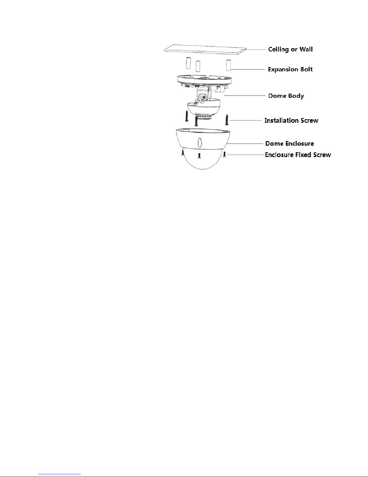
GNC701 Installation
Step 1: Use the included inner hex
wrench to unfasten the dome enclosure.
Step 2: Install Micro SD card (optional).
Step 3: Place and stick the installation
position map on the ceiling or the wall to
suit your desired location.
Step 4: Find and drill the small cross
signs on the map to fit three plastic
expansion bolts holes. Insert the
expansion bolts into the holes.
Step 5: Position the dome body to
match the three screw holes. Fasten
the installation screws to secure the
dome body onto the ceiling or wall. Do not let the cable get caught in between the dome body
and the wall.
Step 6: Adjust the lens viewing direction by rotating the LED cover or rotate the dome bracket
or tilt it vertically. Range of adjustment: vertical (0°~64°), horizontal (0°~355°) & image rotation
(0°~355°).
Step 7: Put on back the dome enclosure according to the hole and fasten the three inner hex
screws firmly.
 Loading...