

Page 1
ANA 9500
Spread Spectrum
Analog PBX
Cordless Telephone
XFER
HOLD
TALK
1
GHI MNO
4
PRS
7
Q
F1
MEMO
CONF
ABC
DEF
3
2
JKL
6
5
TUV
WXY
9
8
OPER
0
F3
F4
F2
POWER
CHARGE
BATT
CHARGE
INUSE/HOLD PAGE/FIND
Operating Guide
Page 2

PRECAUTIONS
Before you read anything else,
please observe the following:
WARNING!
Uniden America Corporation DOES NOT represent this unit to be waterproof.
To reduce the risk of fire, electrical shock, or damage to the unit, DO NOT
expose this unit to rain or moisture.
RECHARGEABLE NICKEL-CADMIUM
BATTERY WARNING
This equipment contains a Rechargeable Nickel-Cadmium
n
Battery.
Cadmium is a chemical known to the State of California to
n
cause cancer.
n
The Rechargeable Nickel-Cadmium Battery contained in this
equipment may explode if disposed of in a fire.
n
Do not short circuit the battery.
n
Do not charge the Rechargeable Nickel-Cadmium Battery
used in this equipment in any charger other than the one
designed to charge this battery as specified in this Guide .
Using another charger may damage the battery, or cause the
battery to explode.
RECHARGEABLE NICKEL-CADMIUM BATTERIES
MUST BE RECYCLED OR DISPOSED OF
PROPERLY
n
Residents Of Minnesota should contact 1-800-225-PRBA for
information concerning reclamation and disposal of
Rechargeable Nickel-Cadmium batteries.
n
Residents outside of Minnesota should contact their local
authorities for information concerning reclamation and
disposal of Rechargeable Nickel-Cadmium batteries.
Page 3

One Year Limited Warranty
WARRANTOR: UNIDEN AMERICA CORPORATION(“Uniden”)
ELEMENTS OF WARRANTY: Uniden warrants, for one year, to the original retail
owner, this Uniden Product to be free from defects in materials and craftsmanship with
only the limitations or exclusions set out below.
WARRANTY DURATION: This warranty to the original user shall terminate and be of
no further effect 12 months after the date of original retail sale. The warranty is invalid if
the Product is (A) damaged or not maintained as reasonable or necessary, (B)
modified, altered, or used as part of any conversion kits, subassemblies, or any
configurations not sold by Uniden, (C) improperly installed, (D) serviced or repaired by
someone other than an authorized Uniden service center for a defect or malfunction
covered by this warranty, (E) used in any conjunction with equipment or parts or as part
of any system not manufactured by Uniden, or (F) installed or programmed by anyone
other than as detailed by the Operating Guide for this product.
STATEMENT OF REMEDY: In the event that the product does not conform to this
warranty at any time while this warranty is in effect, warrantor will repair the defect and
return it to you without charge for parts, service, or any other cost (except shipping and
handling) incurred by warrantor or its representatives in connection with the
performance of this warranty. THE LIMITED WARRANTY SET FORTH ABOVE IS THE
SOLE AND ENTIRE WARRANTY PERTAINING TO THE PRODUCT AND IS IN LIEU
OF AND EXCLUDES ALL OTHER WARRANTIES OF ANY NATURE WHATSOEVER,
WHETHER EXPRESS, IMPLIED OR ARISING BY OPERATION OF LAW,
INCLUDING, BUT NOT LIMITED TO ANY IMPLIED WARRANTIES OF
MERCHANTABILITY OR FITNESS FOR A PARTICULAR PURPOSE. THIS
WARRANTY DOES NOT COVER OR PROVIDE FOR THE REIMBURSEMENT OR
PAYMENT OF INCIDENTAL OR CONSEQUENTIAL DAMAGES. Some states do not
allow this exclusion or limitation of incidental or consequential damages so the above
limitation or exclusion may not apply to you.
LEGAL REMEDIES: This warranty gives you specific legal rights, and you may also
have other rights which vary from state to state. This warranty is void outside the
United States of America.
PROCEDURE FOR OBTAINING PERFORMANCE OF WARRANTY: If, after following
the instructions in this Operating Guide you are certain that the Product is defective,
pack the Product carefully (preferably in its original packaging). Include evidence of
original purchase and a note describing the defect that has caused you to return it, The
Product should be shipped freight prepaid by traceable means, or delivered, to
warrantor at:
Uniden America Corporation
BCS Divison
4700 Amon Carter Blvd.
Fort Worth, TX 76155
(800) 297-1023
8 a.m. to 5 p.m. Central, Monday through Friday
Page 4
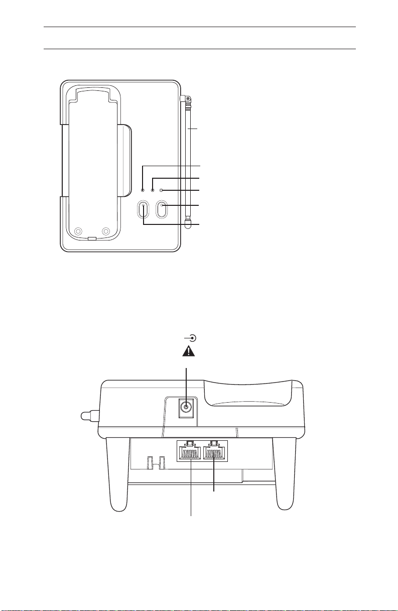
Base Unit Controls & Functions
Base Unit
Antenna
Charge LED
Spare Battery Charge LED
POWER
BATT
CHARGE
CHARGE
INUSE/HOLD PAGE/FIND
DC IN 10V
+
Power On LED
Page / Find Button & LED
Hold Button
Hold / In Use LED
–
AC ADAPTER
LINE
OUT
LINE
IN
Page 5
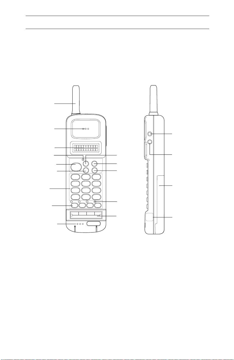
Antenna
Handset Controls & Functions
Earpiece
Display
Talk LED
Talk Button
Conference
Button
Numeric
Keypad
Function
Keys
Microphone
TALK
1
GHI
4
PRS
7
Q
F1 F2
FLASH
2
5
8
0
PAUSE
XFER
CONF
ABC
JKL
TUV
OPER
F3
REDIAL
3
6
9
#
SEARCH
MEMO
F4
R/VOL
s
Volume/
Ringer Select/
Memory
s
MUTE
Transfer
HOLD
Button
Hold Button
Search Up
Mute/
Memory
Search
Down
Memory
DEF
MNO
WXY
Button
Battery
Pack
Function
Key LEDs
Function
Key Labels
HEAD
SET
Head Set
Jack
Page 6

Table of Contents
Handset Controls & Functions............................Inside Front Cover
Base Unit Controls & Functions...........................Inside Back Cover
Important Safety Instructions ...........................................2
About Your ANA 9500 ..............................................4
ANA 9500 Features ................................................5
Installing Your ANA 9500 ...........................................6
Selecting the Installation Location ...............................................6
Connecting the Telephone Line .................................................6
Connecting the Telephone Cords ...............................................7
Tone/Pulse Switch ...........................................................8
Applying Power to the Base Unit ................................................8
Attaching the Belt Clip to the Handset ...........................................10
Installing the Handset Battery Pack .............................................10
Removing the Handset Battery Pack ............................................11
Charging the Handset Battery Pack.............................................11
Low Battery Indicator ........................................................12
Cleaning the Battery Contacts .................................................13
Using Your ANA 9500 Handset .....................................14
ANA 9500 Handset Controls ..............................................14
Using the Handset ..........................................................15
Answering a Call. ...........................................................16
Making a Call ..............................................................16
Feature Buttons .....................................................17
Placing a call “on hold”. ......................................................17
Transferring a Call ..........................................................17
Connecting a Conference Call .................................................17
Programming the Feature Buttons..............................................18
Function Keys .......................................................19
FLASH (F1) ...............................................................19
PAUSE (F2) ...............................................................19
REDIAL (F3)...............................................................19
SEARCH (F4)..............................................................19
Using Your ANA 9500 Memory......................................20
Storing a Number ...........................................................20
Erasing a Stored Number.....................................................21
Dialing with a Stored Number .................................................21
Memory Search ............................................................22
Chain Dialing ..............................................................23
Using Your ANA 9500 Base Unit .......................................24
Placing a Call On Hold.......................................................24
Paging the Handset .........................................................24
Optional Head Set (EXP9530) ..........................................25
Optional Backup AC Adapter (EXP9505) .................................26
Using an Optional Second 2500-type Analog Telephone. ...................27
Typical Applications ..................................................28
Optional Accessories and Replacement Parts ............................29
Trouble Shooting ....................................................30
Specifications .......................................................31
Uniden® is a registered trademark of Uniden America Corporation.
AutoStandbyTM and AutoTalk are trademarks of Uniden America Corporation.
AutoStandby is a patented invention of Uniden America Corporation.
1
Page 7

Important Safety Instructions
When using your telephone equipment, basic safety precautions
should always be followed to reduce the risk of fire, electrical shock,
and injury to persons, including the following:
1. Read and understand all instructions.
2. Follow all warnings and instructions marked on the product.
3. Unplug this product from the wall outlet before cleaning.
Do not use liquid cleaners or aerosol cleaners. Use a dry cloth
for cleaning.
4. Do not use this product near water; for example, near a sink or
in a wet area.
5. Do not place this product on an unstable cart, stand, or table.
The telephone may fall, causing serious damage to the unit.
6. To protect the product from overheating, do not block or cover
any slots or openings in the base Unit. This product should
never be placed near or over a radiator or heat register. This
product should not be placed in a built-in installation unless
proper ventilation is provided.
7. This product should be operated only from the type of power
source indicated on the marking label.
8. Do not allow anything to rest on the power cord. Do not locate
this product where the cord will be damaged by persons walking
on it.
9. Do not overload wall outlets and extension cords, as this can
result in the risk of fire or electrical shock.
10. Never push objects of any kind into this product through the
Base Unit slots, as they may touch dangerous voltage points or
short out parts that could result in a risk of fire or electric shock.
Never spill liquid of any kind on the product.
11. To reduce the risk of electric shock, do not disassemble this
product. Contact qualified service personnel when some
service or repair work is required. Opening or removing covers
may expose you to dangerous voltages or other risks. Incorrect
reassembly can cause electric shock when the appliance is
subsequently used.
12. Unplug this product from the wall outlet and refer servicing to
qualified service personnel under the following conditions:
A. When the power supply cord is damaged or frayed.
B. If liquid has been spilled into the product.
C. If the product has been exposed to rain or water.
2
Page 8

D. If the product does not operate normally when following the
operating instructions. Adjust only those controls that are
covered by the operating instructions. Improper adjustment of
other controls may result in damage, and will often require
extensive work by a qualified technician to restore the product
to normal operation.
E. If the product has been dropped, or the cabinet has been
damaged.
F. If the product exhibits a distinct change in performance.
13. Do not use the telephone to report a gas leak in the vicinity of
the leak.
CAUTION: To reduce the risk of fire or injury to persons by the
battery, read and follow these instructions:
1. Use only the appropriate type and size Battery Pack specified
in this Operating Guide.
2. Do not dispose of the Battery Pack in a fire. The cell may
explode. Check the Nickel-Cadmium Battery Disposal
information at the beginning of this Guide for disposal
instructions.
3. Do not open or mutilate the Battery Pack. Released electrolyte
is corrosive and may cause damage to the eyes or skin. It may
be toxic if swallowed.
4. Exercise care in handling the battery in order not to short the
battery with conducting materials such as rings, bracelets, and
keys. The battery or conductor may overheat and cause burns.
5. Charge the Battery Pack provided with or identified for use with
this product only in accordance with the instructions and
limitations specified in the instruction manual provided for this
product.
6. Observe proper polarity orientation between the Battery Pack
and battery charger.
SAVE THESE INSTRUCTIONS
3
Page 9
About Your ANA 9500
Congratulations on your purchase of the Uniden ANA 9500
Cordless Telephone. The ANA 9500 is designed and engineered
to exacting standards for reliability, long life, and outstanding
performance. It is designed to work with a PBX system. To get the
most from your ANA 9500, please read this Operating Guide
thoroughly. To help familiarize you with the features of your cordless
phone, refer to the Handset illustration foldout from the front cover,
and the Base Unit illustration foldout from the rear cover.
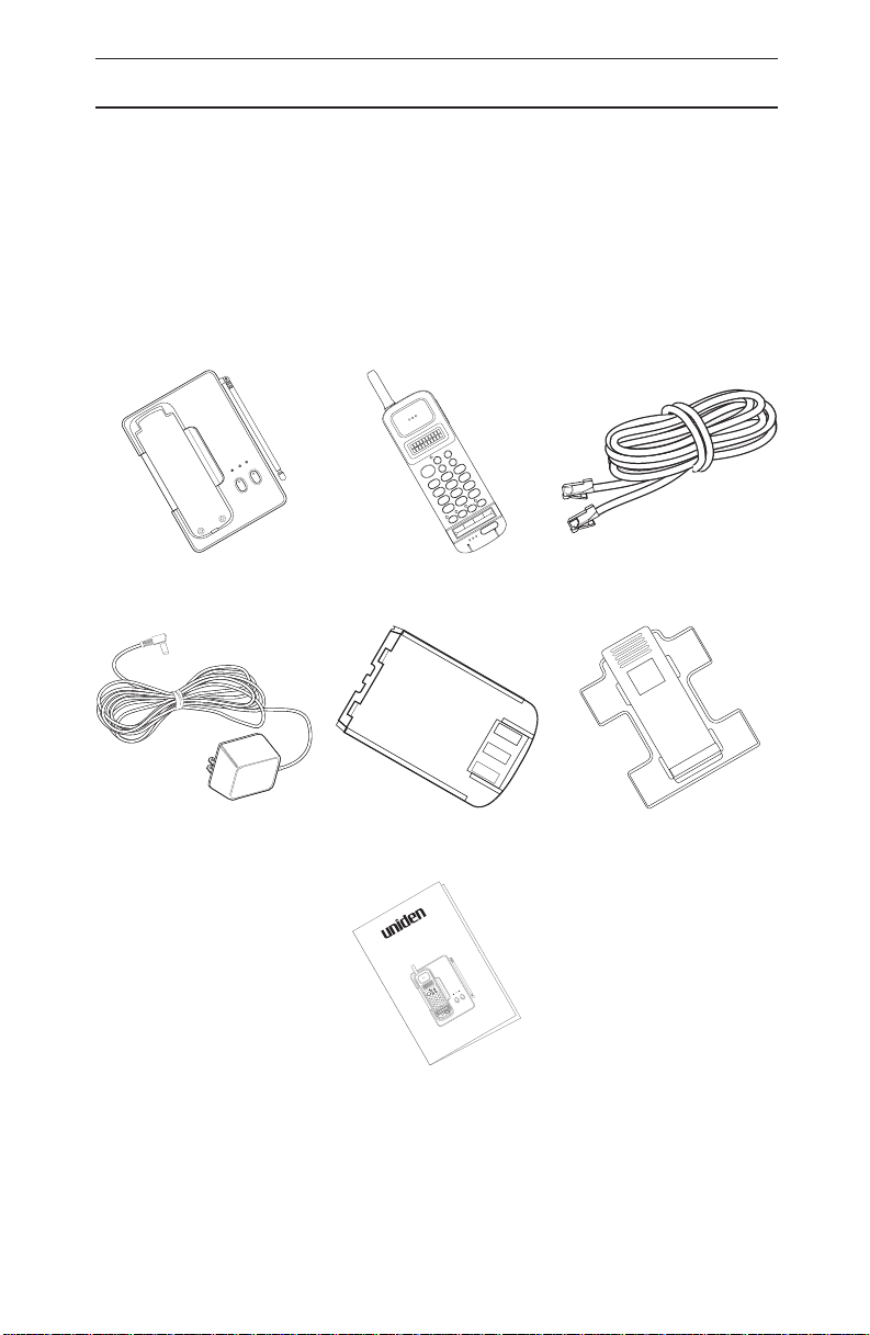
Your ANA 9500 includes the following items:
HOLD
XFER
MEMO
POWER
BATT
CHARGE
CHARGE
PAGE/FIND
INUSE/HOLD
CONF
DEF
3
TALK
ABC
MNO
2
6
JKL
WXY
1
5
9
GHI
TUV
4
8
#
PRS
OPER
7
0
F4
Q
F3
SEARCH
REDIAL
F1 F2
PAUSE
FLASH
Base Unit
EXP950B
AC Adapter
EXP9504
Handset
EXP950H
Rechargeable Battery
EXP9580
®
ANA 9500
Spread Spectrum
Analog PBX
Coredless Telephone
HOLD
XFER
MEMO
CONF
POWER
DEF
BATT
BATT
3
TALK
CHARGE
CHARGE
ABC
CHARGE
MNO
2
6
JKL
WXY
1
5
9
GHI
TUV
PAGE/FINDPAGE/FIND
4
8
#
PRS
OPER
7
0
INUSE/HOLD
F4
Q
F3
F4
F3
F1 F2
F2
F1
Telephone Cord
Belt Clip
EXP9502
Operating Guide
Operating Guide
OMUNIDEXP9500
If any of these items are missing or damaged, contact your PBX
Administrator. If your ANA 9500 is not performing to your
expectations, please try the simple steps listed in the Trouble
Shooting Section of this Guide. If you are still unable to resolve the
problem, contact your PBX Administrator.
4
Page 10

ANA 9500 Features
Super Long Range 900MHz Spread Spectrum
n
2-line, 10-digit LCD Display
n
Headset Jack
n
Ringer Volume Control
n
Handset Volume Control
n
Single button access to: CONFERENCE, HOLD, and
n
TRANSFER features
Four Function Keys: PAUSE, FLASH, REDIAL, SEARCH
n
20 Number Memory Store and Search
n
Battery Charging System for Optional Standby Battery
n
AutoStandby
n
AutoTalk
n
2-Way Handset Mounting
n
Vibrator Ringer Alert
n
Easy Installation
n
Compact Handset Design
n
5
Page 11

Installing Your ANA 9500
Selecting the Installation Location
Select a location for the ANA 9500 to avoid excessive heat or
humidity. The Base Unit of your ANA 9500 can be placed on a
desk or tabletop near a standard 120V AC outlet and telephone line
jack. The Base Unit can also be mounted on a standard AT&T or
GTE wall plate using the optional Wall Mount Adapter. If you will use
the ANA 9500 with a Standard 2500 type Telephone Desk Unit,
place the ANA 9500 near that phone. Keep the Base Unit and
Handset away from sources of electrical noise (motors, fluorescent
lighting, computers).
Connecting the Telephone Line
There are two types of phone outlets:
1) Modular Jack
Plug the telephone line cord from the Base Unit into a standard
modular telephone jack. (Note: If you do not have a modular jack,
contact your local telephone company for information on the
installation of these jacks.)
2) Hard-wired Jack
A modular jack converter (not included) is required. You may
need to rewire when connecting the converter (making
color-coded connections).
Note: Your Uniden Telephone Dealer or a telephone supply store
can advise you on the proper adapter or converter.
6
Page 12
Connecting the Telephone Cords
The ANA 9500 must be connected to an analog PBX port or a
standard analog telephone line.
CAUTION:
Never install telephone wiring during a lightning storm.
n
Never touch uninsulated telephone wires or terminals unless
n
the telephone line has been disconnected at the network
interface.
Use caution when installing or modifying telephone lines.
n
Line "IN"
From
Telephone
Jack
You can also connect a standard 2500-type desk phone to the
ANA 9500:
Line "OUT"
To optional
2500-type
telephone
Connect to the Line OUT Jack
7
Page 13

Tone/Pulse Switch
Be sure the TONE/PULSE switch is in the TONE position.
DCIN 10V
+–
LINEOUT LINE IN
ACADAPTOR
TONE
PULSE
TONE
PULSE
Note: Most systems are Tone dialing. Check with your PBX
Administrator if you are not sure whether your system is Tone
or Pulse dialing.
Applying Power to the Base Unit
Line In
From
Telephone
Jack
AC
Adapter
Use only the supplied AC Adapter: EXP9504
Line Out
to Host
Telephone
DC IN 10V
+ –
LINE OUT LINEIN
ACADAPTOR
Wrap the Power Cord around the
convenient notch on the bottom.
8
Page 14

IMPORTANT! Route the power cord where it will not create a trip
hazard, or where it could become chafed and create a fire or other
electrical hazards.
Note: The AC Adapter furnished with this phone may be equipped
with a polarized line plug (a plug having one blade wider than
the other.) This plug will fit into the power outlet only one way.
If you are unable to insert the plug fully into the outlet, try
reversing the plug.
Do not alter the shape of the blades
of the polarized plug.
Note: If you cannot plug the AC Adapter into the outlet, contact
someone about replacing the outlet.
The unique design of your ANA 9500 allows you to place the
Handset on the Base Unit either face down or face up, with or without
the Belt Clip attached. The Battery Pack in the Handset automatically
recharges in either position.
TALK
1
4
7
F1 F2
F1
Q
2
GHI
5
PRS
8
0
F2 F4
XFER
HOLD
MEMO
CONF
ABC
DEF
3
JKL
MNO
6
TUV
WXY
9
OPER
#
F3
F4
F3
CHARGE
BATT
CHARGE
INUSE/HOLD PAGE/FIND
POWER
CHARGE
BATT
CHARGE
IINUSE/HOLD PAGE/FIND
POWER
9
Page 15

Before using your ANA 9500, be sure to raise the antenna to the
vertical position.
Raise to
Vertical
Position
Attaching the Belt Clip to the Handset
You can use the Belt Clip to attach the Handset to your belt or pocket
for convenient portability.
Snap the tabs of the Belt Clip into
the notches on the sides of the
Handset.
To remove the Belt Clip , pry one
tab at a time from the notch on the
side of the Handset. Carefully lift
the Belt Clip off.
(CAUTION: The Belt Clip is
designed to fit snugly onto the
Handset.)
Installing the Handset Battery Pack
1. Place the Battery Pack onto
the Handset so that it slides
easily along the ridges.
2. Slide the Battery Pack up
onto the Handset until it clicks
into place.
VOL
MUTE
10
Page 16

Removing the Handset Battery Pack
1. Press in on the Battery Pack
Release Latch
2. Slide the Battery Pack off the
Handset
Note: You may have to pull
hard to slide the Battery
Pack off.
Charging the Handset Battery Pack
The Rechargeable Nickel-Cadmium Battery Pack must be fully
charged before using your ANA 9500 for the first time. (Note:
Charge the Standard 400 maH Battery Pack without interruption for
6-8 hours.)
1. Place the Handset on the
Base Unit.
2. Make sure the LED lights. If the
LED doesn’t light, check to see
that the AC Adapter is plugged
in,and that the Handset is
making good contact with the
Base Unit Charging Contacts.
POWER
CHARGE
BATT
CHARGE
11
IINUSE/HOLD PAGE/FIND
Page 17

Charging Spare Battery Packs
The Base Unit of your ANA 9500 is equipped with a Battery
Charger for charging an Optional Spare Battery Pack.
DC IN10V
1. Position the Battery Pack
so the inner side is facing
+ –
LINE OUT LINEIN
ACADAPTOR
toward the top of the
Base Unit.
2. Slide the Battery Pack into
the Charging Compartment
until it clicks into place.
Note: The Battery Pack
(
Charging Compartment has
Tone
Pulse
a latch that keeps the
Battery Pack in place during
charging.)
Make sure the BATTERY CHARGE LED lights. If the
BATTERY CHARGE LED does not light, check to see that the AC
Adapter is plugged in, and that the Battery Pack is seated into the
Charging Compartment.
Note: Charge the Standard 400 maH Battery Pack without
interruption for 6-8 hours. Charge the optional 730 maH maH
Battery Pack without interruption for 8-10 hours.
When charging is complete, press down on the latch to remove the
Battery Pack for use. Or, if you don’t need the Battery pack immediately,
leave it in the Charging Compartment (It will not overcharge.)
Low Battery Indicator
When the Battery Pack in the
Handset is low and needs to be
charged, you will see a message on
the display.
On a Call In Standby Mode
Only the TALK button operates.
Handset beeps once every 3 seconds Handset beeps once.
Complete your call as quickly as possible Cannot make call.
Replace Battery pack within 20 seconds
to continue call.
Return the Handset to the Base Unit for charging or replace the
Handset Battery Pack with another charged Battery Pack.
None of the buttons operate.
Replace Battery Pack before making a
call.
12
Page 18

Cleaning the Battery Contacts
To maintain a good charge, it is important to clean all charging
contacts on the Handset and Base Unit about once a month. Use a
pencil eraser or other contact cleaner. Do not use any liquids or
solvents.
XFER
HOLD
MEMO
CONF
TALK
ABC
DEF
3
1
2
GHI
JKL
MNO
5
6
4
PRS
TUV
WXY
8
7
9
OPER
0
#
F1
F1 F2
Q
F3
F3
F2 F4
F4
CHARGE
BATT
CHARGE
INUSE/HOLD PAGE/FIND
POWER
Contacts
Contacts
13
Page 19

Using Your ANA 9500 Handset
Note: Operation of the ANA 9500 is performed using the Handset
off the Base Unit. The exceptions are charging the Handset Battery
Pack, and terminating a call with AutoStandby. The Base Unit is used
to place a call on HOLD, or to Page the Handset. These operations
are discussed in the Section: “Using Your ANA 9500 Base Unit”.
ANA 9500 Handset Controls
R/VOL
s
s
MUTE
Handset Earpiece
Volume (During a Call
Press VOL on the side of
the Handset to select a
loud or soft Earpiece
volume level.
Ringer Select (Standby
Mode)
Press VOL on the side of
the Handset to select from
RING HIGH
Note: You get a vibrator
alert instead of a ring tone
when you set the Ringer
Volume to RING OFF.
14
Mute
RING LOW
Page 20

Using the Handset
When you pick up the Handset and
press TALK, you will see:
Then you’ll see one of the following:
Condition Indicator LCD Display
Line OK
TALK LED
No Connection to Base
Unit
Channel Busy Error Tone
Line in Use Error Tone
Error Tone
When communication is made
between the Base Unit and the
Handset, the screen will go to
“Standby”, and the phone is ready to
use.
If the Handset is at the range limit of
the ANA 9500, you may see:
Take the following action:
During a Call In Standby Mode
Condition
Action
Warning Tone Can’t make or answer calls
Move back in range within 20
seconds
NO SERVICE
SYSTEM
BUSY
LINE IN USE
(Phone may ring intermittently)
Move back within range.
15
Page 21

Answering a Call
When you receive a call, the Handset
rings and you’ll see:
Handset on the Base Unit Handset off the Base Unit
Pick up the Handset. The AutoTalk
feature allows you to answer the call
immediately.
When you finish the call,, place the Handset back on the Base Unit. AutoStandby
automatically hangs up the phone.
—OR—
Press TALK to hang up the phone.
Press TALK.
Making a Call
(If the Handset is on the Base Unit, pick it up.)
Press TALK. The TALK LED will
light, and you’ll see:
If the Line is all right, enter the
number you are calling. (You can
also dial from memory. See the
section on “Using Memory”.)
When you finish the call, place the Handset back on the Base Unit.
AutoStandby automatically hangs up the phone.
-OR-
Press TALK to hang up the phone.
16
Page 22

Feature Buttons
Note: The exact operation of the Feature Buttons depends on how
your PBX system is configured. Contact your PBX
Administrator for more information.
Placing a call “on hold”
Press HOLD. You’ll hear a “beep”
and see:
To resume the call, press HOLD or TALK.
Transferring a Call
Press TRANSFER. You’ll hear a
“beep”, and see:
Dial the target number.
When the receiving party answers,
press TALK to complete the transfer.
Connecting a Conference Call
To connect a second party to a call in
progress, press CONFERENCE.
You’ll hear a “beep”, and see:
Dial the second party’s number.
When the other party answers, press
CONFERENCE to have a three-way
conversation.
17
Page 23

Programming the Feature Buttons
The Feature Buttons can be programmed for special use, such as
causing a “Hook Flash” followed by a special number or function.
For example — to program the TRANSFER button for “Hook Flash”
and 9 for outside transfers only:
Press MEMO.
Press FLASH.
Press 9.
Press MEMO.
Press TRANSFER.
18
Page 24

Function Keys
FLASH (F1)
Press once to cause a “Hook Flash” while on a call.
Press once to program a “Hook Flash” in a Feature Button.
The FLASH LED lights momentarily while the Key is pressed.
PAUSE (F2)
Press once to program a Pause while storing a number in Memory.
The PAUSE LED lights momentarily while the Key is pressed.
REDIAL (F3)
To dial the last number called, press TALK, then F3 (REDIAL). The
phone will redial the last number called.
The REDIAL LED lights momentarily while the Key is pressed.
SEARCH (F4)
Press to begin Memory Search. (See the following Section for
Memory Search.)
The SEARCH LED remains lit during the Search operation.
19
Page 25

Using Your ANA 9500 Memory
Use these buttons to operate the
ANA 9500 Memory
Storing a Number
1. Press MEMO. You will hear a
beep, and see the message:
2. Enter the number (up to 16 digits)
you want to store.
a. To program a Pause in the dialing
sequence, press.
R/VOL
s
MUTE
s
b. To program a “Hook Flash” in the
dialing sequence, press F1.
3. Press MEMO. You will see the
message:
4. Enter the number (01) -(20) for the
memory location to store. You’ll hear
a confirmation beep and see the
message:
Note: After pressing MEMO the second time, you have
20 seconds to enter the memory location. Otherwise, an
error tone sounds and the unit returns to Standby.
5. The ANA 9500 then returns to Standby mode.
20
Page 26

Example: Store 555-1234 in memory location 12:
a. Press MEMO
b. Enter 5551234
c. Press MEMO
d. Press 12
The Handset beeps confirmation
and you see:
The phone then returns to Standby.
Erasing a Stored Number
1. Press MEMO
2. Press MEMO
3. Enter the memory location number
(01) to (20) you want to clear. You
will hear a long beep and see:
Dialing with a Stored Number
NOTE:The following applies when the phone is in Standby Mode, and
you have already established a connection between Handset
and Base Unit.
1. Press TALK
2. Press MEMO
21
Page 27

3. Enter the Memory Location
(01 - 20)
The phone automatically dials the number shown.
Memory Search
You can search all 20 Memory Locations to find the number you need.
Once you have found the number, you can automatically dial that
number.
1. Press SEARCH (F4)
2. Press ▲ (VOL) to move to Memory
Location 01.
(If Memory Location 01 doesn’t have
a stored number, ▲ will display the
first stored number.
3. a. Press ▲ (VOL) again to move to the
next Memory Location.
3. b. You can also press ▼ (MUTE)to
move to a previous Memory
Location.
3.c. If you press ▼ at Memory Location
01, you’ll move directly to location
20.
4. Once you have the desired number,
press TALK.
The TALK LED lights, and the
SEARCH LED goes out.
The phone will then automatically dial the number.
22
Page 28

Chain Dialing
You can dial any stored number while you are on a call. This is
sometimes needed for Long Distance Access Codes or Account
Access Numbers.
1. While you are on the call, press
SEARCH (F4). The SEARCH LED
lights.
2. Press ▲ (VOL)or▼ (MUTE)as
needed to locate the number in
Memory.
3. Once you have the desired number,
press TALK.
The SEARCH LED goes out, and
the phone dials the number.
23
Page 29

Using Your ANA 9500 Base Unit
Although most of the ANA 9500 operations are performed at the
Handset, there are two operations performed at the Base Unit.
The IN USE/HOLD LED lights
steadily whenever the Handset is
CHARGE
BATT
CHARGE
POWER
connected to a call.
IN USE/HOLD
PAGE/FIND
Placing a Call On Hold
1. Press HOLD on the Base Unit.
The IN USE/HOLD LED blinks, and the call is “on Hold”.
2. To resume the call, press HOLD on the Base Unit, or press
HOLD on the Handset twice.
The IN USE/HOLD LED lights steadily.
Paging the Handset
Press PAGE/FIND on the Base Unit to Page the Handset for a call,
or to find the Handset if it is misplaced.
24
Page 30

Optional Head Set (EXP9530)
The optional Head Set provides a “Hands-Free” Option for the ANA
9500. With the Head Set installed, you can use the Belt Clip to
carry the Handset, and conduct a conversation using the Head Set.
To install the optional Head Set,
open the cover over the
HEAD SET Jack and plug the Head
Set in.
No other settings are needed.
Operation of the ANA 9500 using the Head Set is exactly the same
as using the Handset. However, you will hear through the Head Set
earphone, and talk through the Head Set microphone. The Handset
earphone and microphone (mouthpiece) are disconnected.
25
Page 31

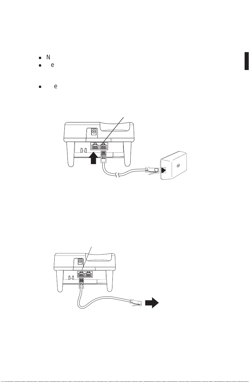
Optional Backup AC Adapter (EXP9505)
The Optional Backup AC Adapter provides protection against losing a
call in case of AC Power failure. The Backup Adapter contains a
Battery Pack that provides enough power for you to complete the call
and hang up.
To install the Backup Adapter:
1. Disconnect the Standard AC Adapter from the Base Unit of the
ANA 9500.
2. Plug the AC Adapter into the jack of the EXP9505.
3. Plug the wire from the EXP9505 into the DC IN jack of the
Base Unit.
To Phone
From AC
Adapter
Backup
AC Adapter
26
Page 32

Using an Optional Second 2500-type
Analog Telephone.
A standard 2500-type Desk telephone can be used with the ANA
9500. Calls can then be answered with the Desk phone and
transferred to the ANA 9500.
Note: A special Security Feature disconnects the Desk phone
whenever the ANA 9500Handset is in use.
Connecting the Desk Telephone.
Connect a telephone cord from the Desk phone to the LINE OUT jack
on the ANA 9500 Base Unit.
Line "OUT"
The Desk phone can now be used to answer or place calls in the
normal manner.
Transferring a Call to the ANA 9500.
1. Press HOLD on the Base Unit.
The IN USE/HOLD LED blinks,
CHARGE
and the call is “on Hold”.
2. Pick up the Handset from the
Base Unit.
IN USE/HOLD
The IN USE/HOLD LED lights
steadily.
The call is now transferred to the ANA 9500, and the Desk phone
is disconnected.
27
BATT
CHARGE
POWER
PAGE/FIND
Page 33

Transferring a Call to the Desk Telephone
1. Press HOLD on either the ANA 9500 Handset or Base Unit.
2. Pick up the Handset of the Desk Phone.
You can now place the ANA 9500 Handset on the Base Unit.
Typical Applications
You can use the ANA 9500 together with a standard PBX
telephone to give you effective business communications both at your
desk and away from it. Contact your PBX Administrator for more
information about your System.
You can have your PBX system programmed so the following
sequence occurs:
1. Your PBX telephone rings first.
2. If you don’t answer the PBX telephone after a set number of
rings, the call is automatically transferred to the ANA 9500.
3. If you don’t answer the call after a set number of rings, it is
automatically transferred to your Voice Mail.
Note: It is good practice to keep the number of rings in each case to
2 or 3. This gives you a chance to answer the call, and doesn’t
keep the other party waiting too long.
28
Page 34

Optional Accessories and Replacement Parts
For the following Optional Accessories and Replacement Parts
contact your PBX Administrator.
AC Adapter
EXP9504
Backup AC Adapter
EXP9505
Base Unit Wall Mount
EXP9590
0
Q
F1 F2
F3
Telephone Cord Belt Clip
EXP9502
400maH Battery
EXP9580
Head Set
EXP9530
730maH Battery
EXP9586
Batt.
Charge Power Charge
Desktop/Wallmount
Charger
EXP9585
®
ANA 9500
Spread Spectrum
Analog PBX
Coredless Telephone
HOLD
XFER
MEMO
CONF
POWER
DEF
BATT
BATT
3
TALK
CHARGE
CHARGE
ABC
CHARGE
MNO
2
6
JKL
WXY
1
5
9
GHI
TUV
PAGE/FIND
4
8
#
PRS
OPER
7
0
INUSE/HOLD
F4
Q
F3
F4
F3
F1 F2
F2
F1
Operating Guide
Vibrator
EXP9570
Operating Guide
OMUNIDEXP9500
29
Page 35

Trouble Shooting
If your ANA 9500 Cordless Telephone is not performing to your
expectations, please try these simple steps. If you are still unable to
resolve the problems, contact your PBX Administrator.
Note: Do not attempt to service this unit yourself. All service must be
done by qualified service personnel.
Problem Suggestion
Make sure the AC Adapter is plugged into
Charge light won’t come
on when Handset is
placed in Base Unit.
Conversation
interrupted frequently.
Warning tone and NO
SERVICE message.
Handset doesn’t ring.
•
the Base Unit and wall outlet.
Make sure Handset is properly seated in
•
Base Unit.
Make sure the Nickel-Cadmium Battery
•
Pack is properly placed on the Handset.
• Make sure that the charging contacts on
the Handset and Base Unit are clean.
Make sure that the Base Unit antenna is
•
fully vertical.
• Move closer to the Base Unit.
• Check for LOW BAT warning.
• Move closer to the Base Unit.
•
Nickel-Cadmium Battery may be weak.
Charge the Battery Pack for 8-10 hours.
•
Check the Ringer Alert setting. It may be
on RING OFF without the optional
Vibrator Alert installed.
•
Make sure the Base Unit antenna is fully
vertical.
•
The Handset may be too far away from
the Base Unit.
30
Page 36

Specifications
General
Frequency Control : Phase Lock Loop
Modulation : MSK
Operating Temperature : -10 to 50 C
Base Unit
Receive/Transmit Frequency : 902 MHz to 928 MHz Spread Spectrum
Power Requirements : 10V DC from supplied AC Adapter
3
Size : 7
in. W X
4
7
8
Weight : Approx. 1lb., 5 oz.
Handset
Receive/Transmit Frequency : 902 MHz to 928 MHz Spread Spectrum
Power Requirements : Rechargeable Ni-Cd Battery Pack
Size : 2
1
in. W x
8
Weight : Approx. 8.6oz. with battery
Battery : Capacity 400 mAH, 4.8V
Talk Mode 3 hours (typical)
Standby Mode 42 hours (typical)
Specifications shown are typical and subject to change without notice.
in. D X 3
7
in. D x 6
8
5
in. H
32
1
in. H with antenna
2
31
Page 37

Covered under one or more of the following U.S. patents:
®
4,511,761 4,523,058 4,595,795, 4,597,104
4,797,916 4,803,491 5,157,686 5,253,268
and other patents pending.
OMUNIDEXP9500 ©1995 Uniden America Corporation. Printed in the USA
All rights reserved.
 Loading...