


ProSeries
IP CAMERA
INSTALLATION GUIDE
4KTPD-MVF
4MTPD-MVF
4MTPD-2.8
2MTPD-VF
4MMD-2.8
2MMD-2.8
4MED-3.6
2MED-3.6
© 2018 Uniden America Corporation
Irving, Texas
Issue 1, April 2018
2MTD-2.8
4KB-MVF
4MB-MVF
2MB-VF
4MB-3.6
2MB-3.6

Uniden surveillance products are not manufactured and/or sold with the intent to be used for illegal
purposes. Uniden expects consumer’s use of these products to be in compliance with all local,
state, and federal law. For further information on video surveillance and audio recording legal
requirements, please consult your local, state and federal ofcials.
Uniden constantly works on improving our products. This includes updating our documentation
with the latest rmware changes. Go to www.uniden.com to nd the latest version of all
documentation.
© 2018 Uniden America Corporation
All rights reserved.

3
CONTENTS
OVERVIEW .............................................. 5
WHAT’S INCLUDED ........................................5
INSTALL CAMERAS ...................................... 5
INSTALLATION TIPS .......................................5
TAMPER-PROOF DOMED CAMERAS .......................... 6
INSTALL MINI DOME CAMERA ..............................8
What’s Included ...............................................8
Install Camera ................................................8
INSTALL EYEBALL DOME CAMERA ..........................9
What’s Included ...............................................9
Install Camera ................................................9
INSTALL TURRET DOME CAMERA ..........................10
What’s Included ..............................................10
Install Camera ...............................................10
INSTALL LARGE BULLET CAMERAS .........................11
What’s Included ..............................................11
Install Camera ...............................................12
INSTALL SMALL BULLET CAMERAS ......................... 12
What’s Included ..............................................12
Install Camera ...............................................13
CONNECTING THROUGH PC .............................. 13
USING DEVICEMANAGER TOOL ............................13
WEB ACCESS ............................................14
Set Security Levels ...........................................15
UNIDEN PROSERIES MOBILEPHONE CLIENT ................ 16
SOFTWARE OPERATING ..................................16
Add device ...............................................17
SPECIFICATIONS ....................................... 18
TAMPER-PROOF DOME CAMERAS .......................... 18
MINI AND EYEBALL DOME CAMERAS ........................19

4
TURRET DOME AND LARGE BULLET CAMERAS ...............20
SMALL BULLET CAMERAS ................................. 21
COMPLIANCE .......................................... 22
FCC PART 15 .............................................22
IC ......................................................23
THREE-YEAR LIMITED WARRANTY ........................ 23
5
INSTALLATION
OVERVIEW
Uniden’s IP cameras can be installed in either Uniden’s NVR or XVR surveillance systems.
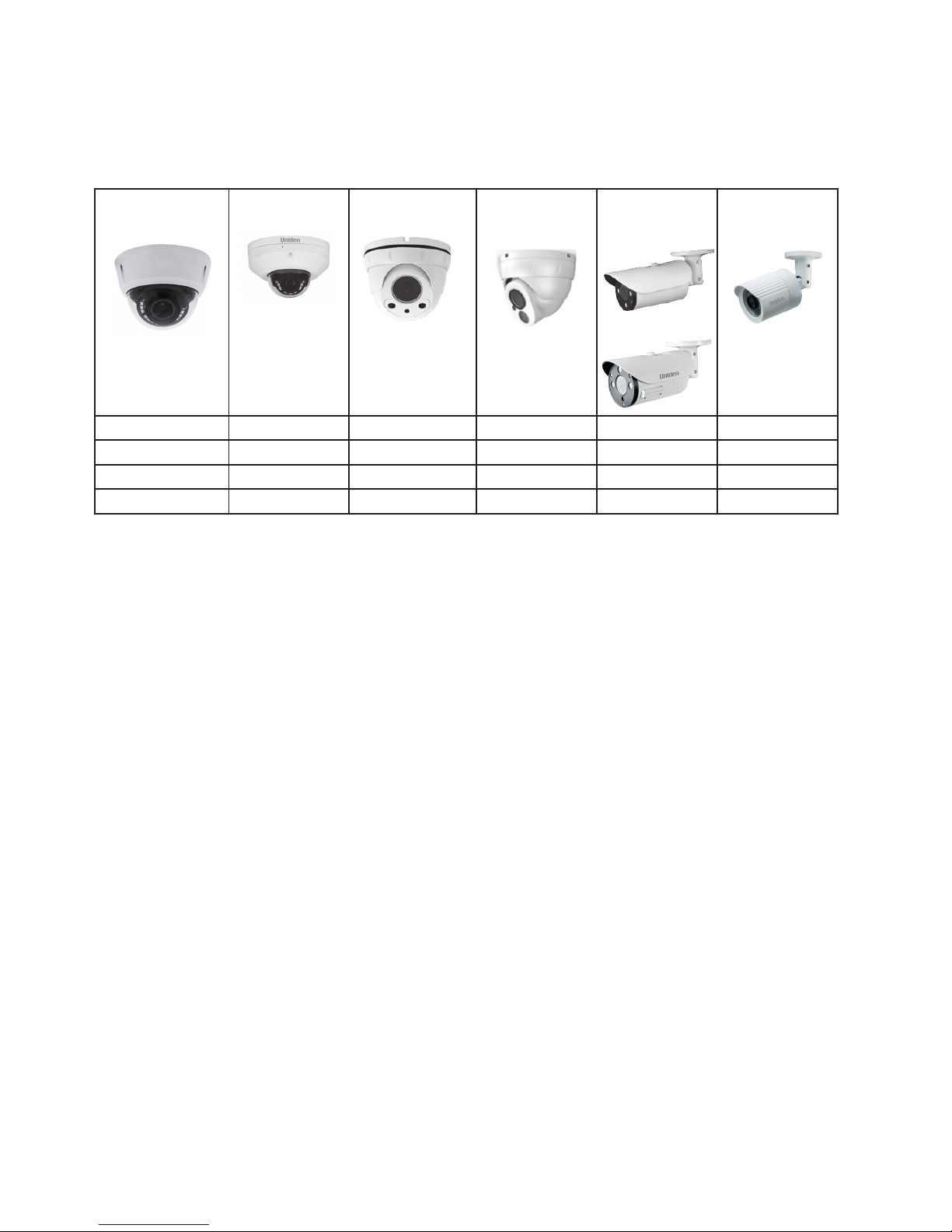
TAMPER-
PROOF DOME
MINI DOME EYEBALL
DOME
TURRET
DOME
LARGE
BULLET
SMALL
BULLET
4KTPD-MVF 4MMD-2.8 4MED-3.6 2MTD-2.8 4KB-MVF 4MB-3.6
4MTPD-MVF 2MMD-2.8 2MED-3.6 4MB-MVF 2MB-3.6
4MTPD-2.8 2MB-VF
2MTPD-VF
WHAT’S INCLUDED
• IP camera
• Mounting template sticker
• Star-tipped Allen wrench
• 2-wire to 2.1mm barrell plug for optional 12V DC power input
• Installation screws and anchors
Network cable and power source are not included. SD cards are not included. If you
plan on using the Automatic Network Restoration feature in the NVR, you will need to
purchase an SD card.
INSTALL CAMERAS
INSTALLATION TIPS
• When selecting an outside location for your cameras, keep in mind that most cameras
are designed to operate between 14°F to 122°F (-10°C to 50°C) with a relative humidity
of up to 95%. Avoid installing cameras in direct sunlight, and consider wind chill and other
environmental factors, too.
• Mount the camera in an area that is visible, but out of reach. Route the wiring so it does not
interfere with power or telephone/cable lines and it should not be where it could be easily cut.
Create a plan for camera wire routing and for camera angle.
• Adjust the camera angle so that it covers an area with high trafc as needed. In “high-
risk” locations, have more than one camera cover the same area. This provides camera
redundancy if a vandal attempts to damage a camera.
• If you position cameras indoors, avoid pointing the camera at a glass window to see outside.
This may result in a bright white ring in the night vision image because the light from the night
vision LEDs may reect off the window glass.
Take the following placement suggestions under consideration:
6
• Cabling Distance From NVR to Camera. The video signal sent from the camera to the DVR
is reduced over distance. The maximum distance allowed is 330 feet (100 meters). A 60 foot
cable is included. If you need a cable longer than 60 feet, then use an RG59 cable (with
suitable connectors).
• Do not submerge any camera.
• Mounting. Ensure the camera is mounted on a stable surface which is capable of supporting 5
times the weight of the camera.
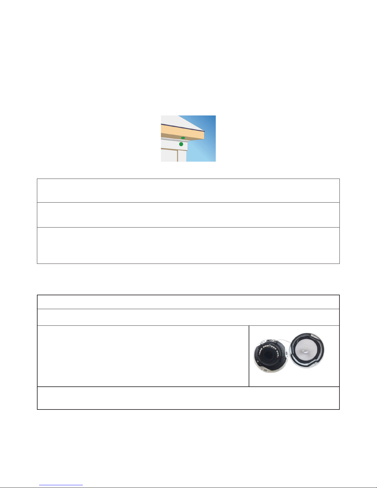
• Avoid direct exposure to the weather. Cameras which are weatherproof may be mounted
outside, such as under an eave or other overhang; however, the image will be affected by rain,
etc., landing on the lens. Do not allow direct sunlight to land on the lens.
1. With the DVR connected to the camera, hold it in the location where you want it mounted.
Check the display on the monitor to verify that the view from that location is acceptable.
2. Mount the camera(s) to the desired surface using the parts in the supplied mounting kit. If
mounting on drywall, use the drywall anchors supplied in the kit.
3. Adjust the camera to ensure that the camera has a satisfactory view of the area you would
like to monitor. Cameras have several adjustment points to provide maximum exibility when
setting the view angle.
TAMPER-PROOF DOMED CAMERAS
1. Remove the camera and accessory items from the box. Verify that all parts are there.
2. Position the installation template sticker on the location (wall, ceiling, etc). Drill a 1” hole as
indicated on the sticker and install anchors and screws.
3. Unscrew the camera from the housing, allowing the camera to
separate from the housing and clear dome.
4. Connect the camera’s network cable tail to the house cabling through the 1” hole.
7
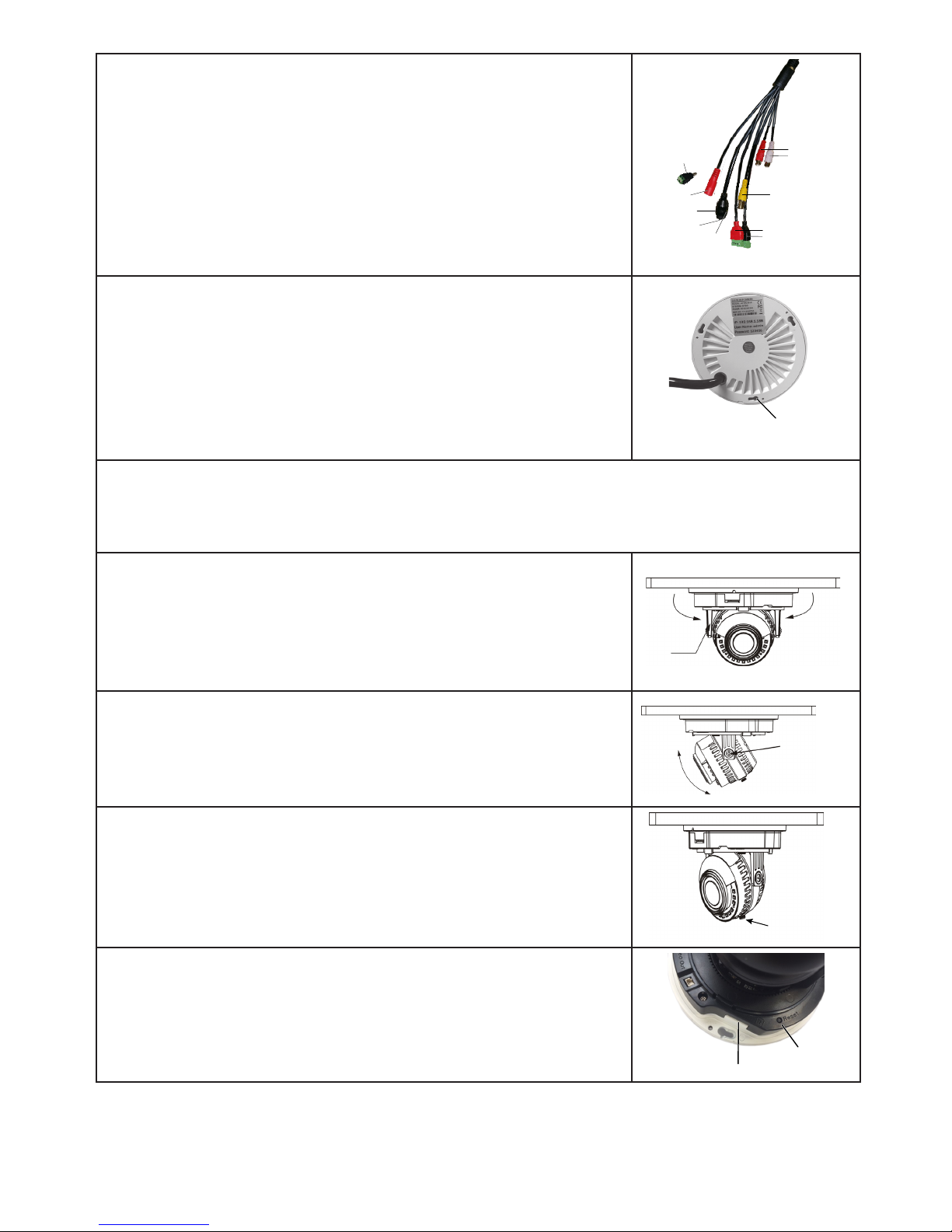
5. If you have a 4K TPD camera, connect the plugs from the
network cable tail to their appropriate cables.
When using an optional external power supply, the AC
socket outlet shall be installed near the equipment and be
easily accessible.
If installed outdoors, the cable and all cable connections
must be routed inside the wall.
White - Audio Out
Red - Audio In
Yellow - Video (BNC)
Black - Alarm In
Red - Alarm Out
RJ45
Red - 12VDC (optional)
Network
Activity
LEDs
PoE
2.1mm Barrel Adapter
NOTE: 12VDC power supply
not included
6. Align the camera base screw holes to the screws. Hang the
base onto the screws then slide the base along the screw lock
to secure.
Screw Hole
and Lock
7. Remove the protective lms from the inside and outside of the camera dome and clean the
dome with a microber cloth (not included) if available.
Do not use a paper towel to clean the camera lens or dome as it might leave
scratches.
8. Adjust the bracket to swivel the camera up to 175˚ on a
horizontal axis (orients the camera for top/bottom of frame).
Bracket
Swivel
Direction
Swivel
Direction
9. Loosen screw 1 and adjust the camera from 15 - 90˚ on a
vertical axis.
15˚ - 90˚
Screw 1
10. Loosen screw 2 to ne-tune the horizontal axis (+/- 30˚).
As you adjust the camera position, check it through the
NVR Preview screen.
Screw 2
11. Insert an SD card if needed.
SD Card Slot
Reset Button
8
12. Remove the dessicant packet from the sealed plastic envelope
and position it inside the camera.
13. Screw the housing back onto the camera base.
INSTALL MINI DOME CAMERA
What’s Included
• IP camera
• Mounting template sticker
• Star-tipped Allen wrench
• 2-wire to 2.1mm barrell plug for optional 12V DC power input
• Installation screws and anchors
• Dessicant package
Install Camera
1. Remove the camera and accessory items from the box. Verify that all parts are there.
2. Position the installation template sticker on the location (wall, ceiling, etc). Drill a 1” hole as
indicated on the sticker and install anchors and screws.
3. Unscrew the camera from the housing, allowing the camera to
separate from the housing and clear dome.
4. Connect the camera’s network cable tail to the house cabling
through the 1” hole.
When using an optional external power supply, the AC
socket outlet shall be installed near the equipment and be
easily accessible.
If installed outdoors, the cable and all cable connections
must be routed inside the wall.
RJ45
Red - 12VDC (optional)
PoE
2.1mm Barrel Adapter
NOTE: 12VDC power supply
not included
5. Align the camera base screw holes to the screws. Hang the
base onto the screws then slide the base along the screw lock
to secure.
Screw Hole
and Lock
6. Remove the protective lms from the inside and outside of the camera dome and clean the
dome with a microber cloth (not included) if available.
Do not use a paper towel to clean the camera lens or dome as it might leave
scratches.

9
7. Adjust the collar to swivel the camera up to 175˚ on a horizontal
axis (orients the camera for top/bottom of frame).
As you adjust the camera position, check it through the
NVR Preview screen.
Thumb
Control
Adjustable
collar
8. Insert an SD card if needed.
SD Card Slot
Reset Button
9. Remove the dessicant packet from the sealed plastic envelope
and position it inside the camera.
10. Align the tab on the housing with the slot on the camera base
for easier reassembly. Tighten screws.
INSTALL EYEBALL DOME CAMERA
What’s Included
• IP camera
• Mounting template sticker
• Star-tipped Allen wrench
• 2-wire to 2.1mm barrell plug for optional 12V DC power input
• Installation screws and anchors
• Dessicant package
Install Camera
1. Remove the camera and installation items from the box. Verify that all parts are there.
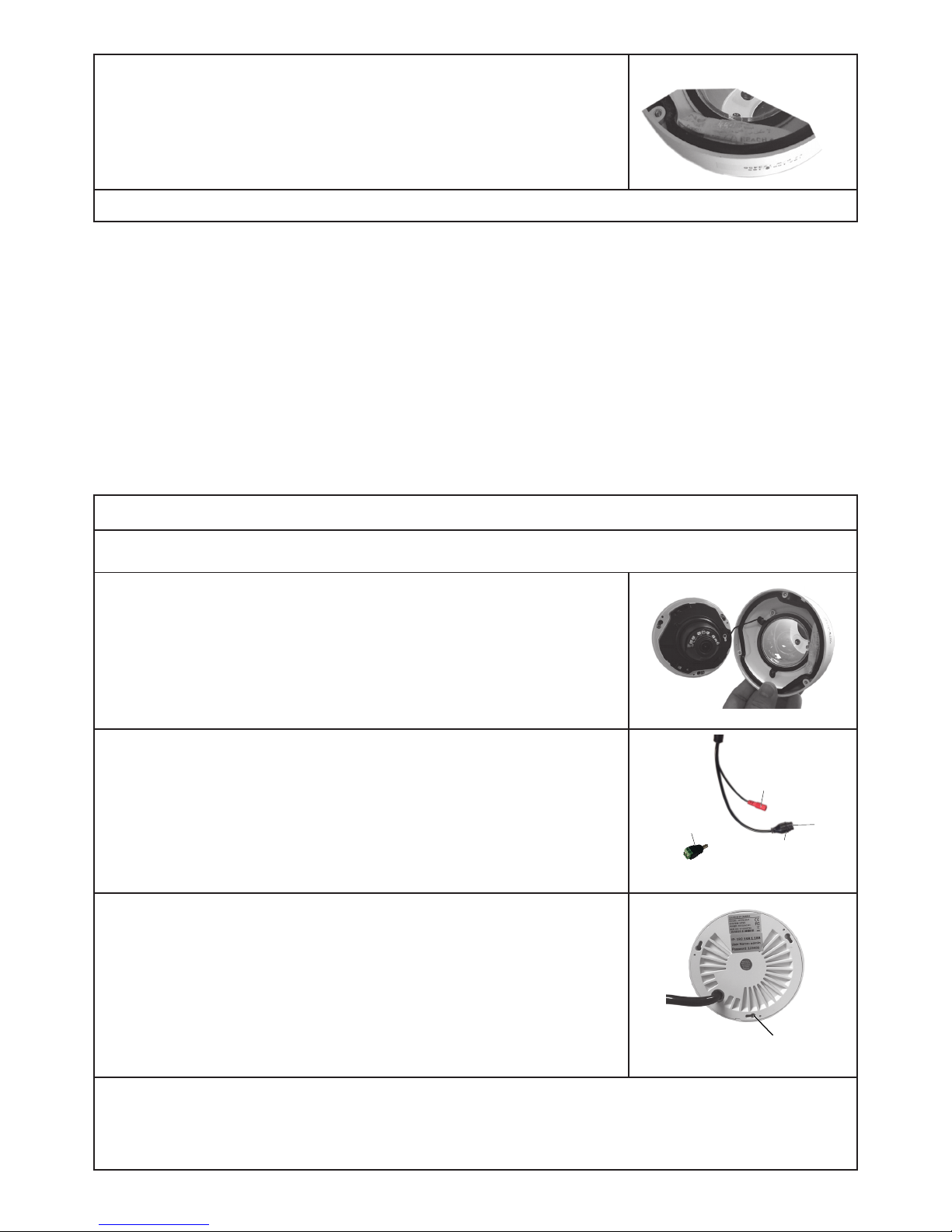
2. Hold the camera and sleeve steady and unscrew the ring from
the base.
Base
Ring
Camera
Sleeve
3. Position the installation template sticker on the location (wall, ceiling, etc). Drill a 1” hole as
indicated on the sticker. Install the anchors.
4. Position the base on the template, aligning the screw holes to the anchors, and screw it into
position.

10
5. Connect the network cable tail to the house cabling through the
1” hole.
When using an optional external power supply, the AC
socket outlet shall be installed near the equipment and be
easily accessible.
If installed outdoors, the cable and all cable connections
must be routed inside the wall.
RJ45
Red - 12VDC (optional)
PoE
2.1mm Barrel Adapter
NOTE: 12VDC power supply
not included
6. Unscrew the hatch on the camera to insert an SD card if
needed.
7. Remove the dessicant packet from the sealed plastic envelope
and position it inside the camera.
8. Reassemble the camera, sleeve, and ring. Position the assembly onto the base and adjust
the camera to the correct viewing angle.
As you adjust the camera position, check it through the NVR Preview screen.
9. When the viewing angle is correct, tighten the ring to the base.
As you tighten the ring, keep adjusting the camera as needed.
INSTALL TURRET DOME CAMERA
What’s Included
• IP camera
• Mounting template sticker
• Star-tipped Allen wrench
• 2-wire to 2.1mm barrell plug for optional 12V DC power input
• Installation screws and anchors
• Dessicant package
Install Camera
1. Remove the camera and installation items from the box. Verify that all parts are there.

11
2. Hold the camera and sleeve steady and unscrew the ring from
the base.
Base
Ring
Camera
Sleeve
3. Position the installation template sticker on the location (wall, ceiling, etc). Drill a 1” hole as
indicated on the sticker. Install the anchors.
4. Position the base on the template, aligning the screw holes to the anchors, and screw it into
position.
5. Connect the network cable tail to the house cabling through the
1” hole.
When using an optional external power supply, the AC
socket outlet shall be installed near the equipment and be
easily accessible.
If installed outdoors, the cable and all cable connections
must be routed inside the wall.
RJ45
Red - 12VDC (optional)
PoE
2.1mm Barrel Adapter
NOTE: 12VDC power supply
not included
6. Reassemble the camera unit. Remove the dessicant packet from the sealed plastic envelope
and position it inside the camera unit.
7. Screw the camera unit to the base securely enough to adjust
the camera position. Double check the position through the
NVR Preview screen.
Use an oil-free soft brush or blow gently into the camera
dome to clear any dust or dirt.
Set Screw
Location (x2)
8. Tighten the ring to the base. Insert the set screws to lock the camera into position.
INSTALL LARGE BULLET CAMERAS
What’s Included
• IP camera
• Mounting template sticker
• Camera-specic Allen wrench
• 2-wire to 2.1mm barrell plug for optional 12V DC power input
• Installation screws and anchors
• Dessicant package

12
• Rubber plug (grommet) to seal network cable hole
Install Camera
1. Remove the camera and installation items from the box. Verify that all parts are there.
2. Position the installation template at the location (wall, ceiling, etc). Drill a 1” hole as indicated
on the sticker and install the anchors provided.
3. If your bullet camera is equipped with an SD slot, insert an
SD card now before you install the camera. Unscrew the
rectangular hinged panel and insert the SD card.
SD Card Slot
Reset Button
4. Thread the network cable tail through the grommet and connect
it to the house cabling through the 1” hole. Plug the grommet
into the hole. Using the screws provided, screw the camera
base into position.
When using an optional external power supply, the AC
socket outlet shall be installed near the equipment and be
easily accessible.
If installed outdoors, the cable and all cable connections
must be routed inside the wall.
White - Audio Out
Red - Audio In
Yellow - Video (BNC)
Black - Alarm In
Red - Alarm Out
RJ45
Red - 12VDC (optional)
Network
Activity
LEDs
PoE
2.1mm Barrel Adapter
NOTE: 12VDC power supply
not included
4KB-MVF
RJ45
Red - 12VDC (optional)
PoE
2.1mm Barrel Adapter
NOTE: 12VDC power supply
not included
4MB-MVF, 2MB-VF
5. Loosen screw 1 to rotate the camera and stand up to 360°.
Loosen screw 2 to adjust the camera body up to 90° and screw
3 to fine tune the camera position up to 90°. Loosen Screw 4 to
adjust the sun shade.Check the camera’s position through the
NVR Preview screen as you adjust the camera.
Screw 1
Screw 2
Screw 3
Screw 4

13
6. Unscrew the access cover and swing it open. Unscrew the
adjustment levers just enough to move them and adjust the
image. Check the camera view through the NVR Preview
screen.
• Zoom - Move lever to the left for Telephoto (zoom in) and to the
right for Fish-Eye (zoom out).
• Focus - Move lever to left and right to adjust focus.
7. Tighten the adjustment lever screws when complete and close
the compartment.
Cover
Focus
Zoom
INSTALL SMALL BULLET CAMERAS
What’s Included
• IP camera
• Mounting template sticker
• Camera-specic Allen wrench
• 2-wire to 2.1mm barrell plug for optional 12V DC power input
• Installation screws and anchors
• Dessicant package
• Rubber plug (grommet) to seal network cable hole
Install Camera
1. Remove the camera and installation items from the box. Verify that all parts are there.
2. Position the installation template at the location (wall, ceiling, etc). Drill a 1” hole as indicated
on the sticker and install the anchors provided.
3. Thread the network cable tail through the grommet and connect
it to the house cabling through the 1” hole. Plug the grommet
into the hole. Using the screws provided, screw the camera
base into position.
When using an optional external power supply, the AC
socket outlet shall be installed near the equipment and be
easily accessible.
If installed outdoors, the cable and all cable connections
must be routed inside the wall.
RJ45
Red - 12VDC (optional)
PoE
2.1mm Barrel Adapter
NOTE: 12VDC power supply
not included
4. Loosen screw 1 to rotate the camera and stand up to 360°.
Loosen screw 2 to adjust the camera body up to 90° and
screw 3 to fine tune the camera position up to 90°. Check the
camera’s position through the NVR Preview screen as you
adjust the camera.
Screw 1
Screw 2
Screw 3
5. Once positioned, tighten all screws to secure.
14
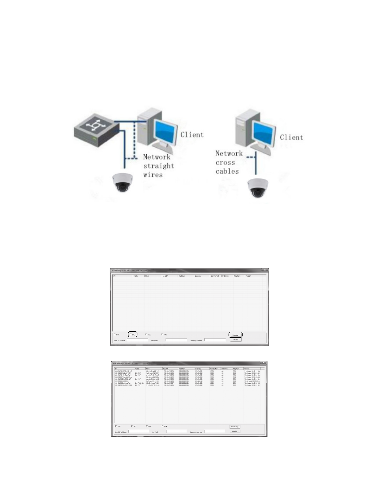
CONNECTING THROUGH PC
Running the DeviceManager tool on your PC lets you easily identify cameras’ IP addresses,
Subnet Masks, and Gateways. Use this information to view and congure cameras through the
browser.
From Internet Explorer, go to support.uniden.com/pro-support and select VMS & CMS. From the
Video Management System screen, select Download VMS to download the plugin.
USING DEVICEMANAGER TOOL
1. Open DeviceManager. The main Device Manager screen displays.
2. Check IPC, then select Discover. A list of IP cameras on the network displays.
DeviceManager - IP Search Option
DeviceManager - IP Cameras Discovered
NOTE: This tool can also modify IP addresses when setting a network camera IP
address with the device IP address and computer IP address in the same net.

15
WEB ACCESS
1. Input the network camera IP address in the browser address bar to log in. A pop-up browser
control installation message automatically displays. Click to download and install. The following
description uses Internet Explorer as example.
Network camera factory initial information is:
. . . IP address: 192.168.1.188
. . . http port: 80
. . . Manage user: admin
Install Plugins No Plugins
2. After installing the plugins, input the network camera IP address again; a login popup prompts
you to set the password.
NOTE: In order to improve network security, the network camera password needs to be
8 - 16 alphanumeric characters.
NOTE: Entering an incorrect password 3 times locks the camera for about 30 seconds.
Set Password Request Setting Password
3. After setting the password, enter the login interface. Input the network camera user name and
password to log into the system.
Login Interface
NOTE: If you have modied the initial IP address, please use the modied IP address to
log into the network camera.
16
Set Security Levels
NOTE: After installing the controls, if the pop-up login interface always reminds you
to download and install the Activex control, try upgrading your IE browser to IE11 and
reducing the IE security level.
1. Open the IE browser and select Tools/Internet Options/Security/Customized Level. Set the
security level to Medium High (default) or Medium Low.
2. Select Tools/Internet Options/Security/Customized level.
• Enable ActiveX controls and plugins.
• Enable the marked as safe ActiveX-controlled execution scripts.
• Initialize and execute the unmarked as safe ActiveX-controlled execution scripts.
• Download unsigned ActiveX controls.
• Download the signed ActiveX controls.
• Run ActiveX controls and plugins.
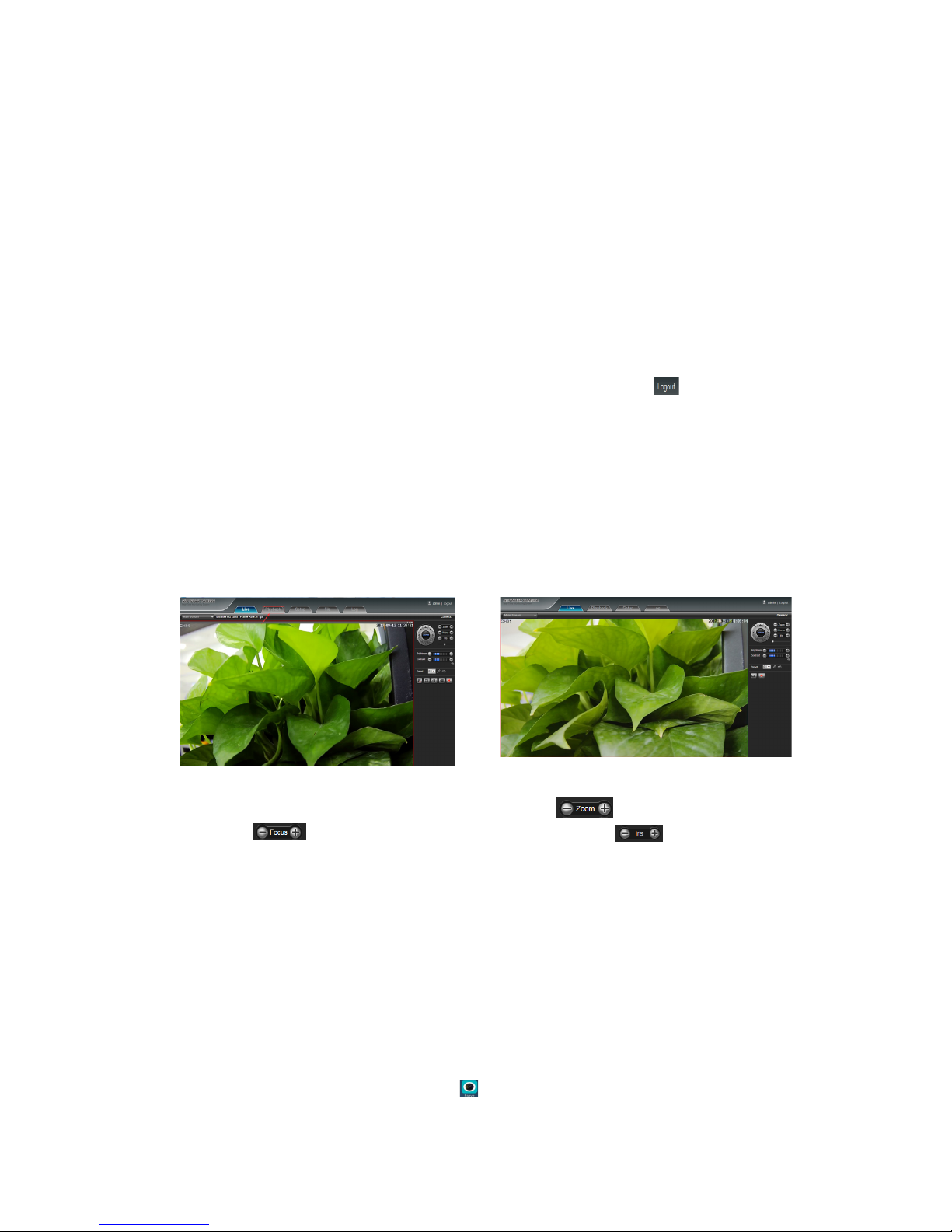
3. When entering into the network camera main interface, you can click
on the top right corner
to exit system safely.
4. On the network camera main interface, you can operate real-time preview, video playback,
parameter conguration, le management, and log search.
NOTE: This fully functional interface is displayed when SD card is inserted into the
device. If no SD card is inserted, a simple interface of the device includes real-time
preview, parameter conguration, le management, and log search (except the video
playback).
NOTE: Under no plugins mode, insert an SD card to display fully functional interface.
NOTE :When the device is motorized lens, zoom is to adjust length of the
focal length, focus
is to adjust the image resolution, iris is to adjust the size of
the iris.
NOTE: No image or interface displays abnormally after login, rstly clear the cache,
unload controls, then install the new controls unload controls: close IE, enter Windows
system contents, nd the installation content (the default content is C: \ Program Files
\ webactivex - rtsp or C: \ Progra Iles (x86) \ webactivex - rtsp) the related controls
information in the folder, run unins000. Exe les, the system will automatically delete.
UNIDEN PROSERIES MOBILEPHONE CLIENT
SOFTWARE OPERATING
1. After install successfully, click software icon on the mobile phone, then the software will be
running and start procedure to enter into login interface.

17
FUNCTIONS DESCRIPTION
Remove Login Account login, device information can store in the
cloud storage.
Remember Password The app remembers the current account password.
Password modication Modies the registered user password.
Local Login Can directly login without account; device stores the
information in the phone.
User Register The account is used for storing customer information
and related device list in the cloud storage.
User Name User Name
1. Log in with a registered user name/password. Enter the Device List management interface.

18
ICON FUNCTION INTRODUCTION
Return to main menu.
Add device.
Device; click to play all channels.
Add device
1. Click Add icon in the upper right corner to display the Add Device interface.
2. Manually add a device’s connection parameters; select the Search button to search and add
devices in the LAN.
Add Device Contact List
• Connection mode: There are two methods to create serial number and IP/Domain direct
connections. The cloud method connects a device via serial number; the IP/Domain method is to
connect device via traditional IP address or dynamic domain name and port. Adopt serial number
to add device for default; click upper IP/Domain to switch IP/Domain method .
Note: When selecting IP/Domain mode to add device, if it lls the intranet IP address in
the IP item eg: begin with192.168.*.*, it can only connect the preview in LAN, it will fail

19
to connect the preview while using the outer net. Need to connect monitor through the
network,and must use the serial number or domain name to add device)
• Name: The monitoring device name. This user-created identier identifes a device’s location and
according to the place name. It displays under the device icon and shows on the title during video
playback.
• Serial number: Device cloud connects to the only serial number, which can be obtained via
searching the LAN. Click the QR code icon
on the right side to scan the network’s input QR
code in the Web client display. The device directly scans Query Device ID QR code when using
Uniden’s mobile phone client.
• User name: The user name of front-end device; default = admin.
• Password: Password of front-end matches with its user name; default = blank.
3. After completing settings, click Conrm. The system automatically pre-connects to check
whether device information validity. If it is correct, it automatically returns to the Device list. If
incorrect, it will display an error message that you have to conrm and add again.
SPECIFICATIONS
TAMPER-PROOF DOME CAMERAS
4KTPD-MVF 4MTPD-MVF 4MTPD-2.8 2MTPD-VF
GENERAL
IR Distance 100’ Night Vision (12 IR LEDs)
Protection Grade IP66/IK10 IP66/IK09 IP66
Power PoE/12VDC
(optional)
Power Jack 2.1mm Power Jack for optional 12VDC input
Power
Consumption
<9W <8W
Operating Temp -4°F~131°F
(-15.5°C~55°C)
Operating Humidity 0% - 90%
Dimensions (inch) 4.61 (L) x 4.61 (W) x 3.39 (H)
CAMERA
Sensor 1/2.5” 8MP
progressive scan
CMOS
1/3” 4MP progressive
scan CMOS
1/2.9” SONY
2.07 MP
Progressive
scan Exmor
CMOS
Max. Resolution 3840 x 2160 2592 x 1520 1920 x 1080
Min. Illumination 0Lux/F1.4 (IR on)
Lens 3.0 - 10mm
motorized lens
2.8 - 12mm
motorized lens
2.8mm Fixed 2.8-12mm
Varifocal
Electronic Shutter Auto/Manual
(1/25~1/10000), FLK

20
4KTPD-MVF 4MTPD-MVF 4MTPD-2.8 2MTPD-VF
R/N Ratio ----- ≥35db (AGC OFF) ≥50db (AGC
OFF)
Analog Video
Output
/ / 1CH 1.0Vp-p
complex video output
Output Model PAL/NTSC adjustable
MINI AND EYEBALL DOME CAMERAS
4MMD-2.8
(MINI DOME)
2MMD-2.8
(MINI DOME)
4MED-3.6
(EYEBALL
DOME)
2MED-3.6
(EYEBALL
DOME)
GENERAL
IR Distance 30’ Night Vision
(6 IR LEDs)
100’ Night Vision
(2 IR array
LEDs)
100’ Night
Vision
(36x5 IR LEDs)
Protection Grade IP66, IK10 IP66 IP66
Power PoE/12VDC
(optional)
Power Jack 2.1mm Power Jack for optional 12VDC input
Power
Consumption
<8W <6W <8W <7W
Operating Temp -4°F~131°F
(-15.5°C~55°C)
-14°F~122°F
(-9.7°C~50°C)
Operating Humidity 0% - 90%
Dimensions (inch) 4.61 (L) x 4.61 (W)
x 3.39 (H)
4.61 (L) x 4.61 (W)
x 2.6 (H)
4.72 (L) x 4.72
(W) x 3.87 (H)
4.72 (L) x 4.72
(W) x 3.87 (H)
CAMERA
Image Sensor 1/3” 4MP progressive scan CMOS 1/2.9” SONY
2.07 MP
Progressive
scan Exmor
CMOS
Effective Pixels ----- 2MP 2MP
Max. Resolution 1920 x 1080 1920 x 1080 2592 x 1520 1920 x 1080
Min. Illumination 0Lux/F1.4 (IR on) Color: 0.5Lux/F1.4, B/W:0.2Lux/F1.4
Lens 2.8mm lens 3.6mm 3.6mm ICR lens
Electronic Shutter Auto/Manual
(1/25~1/10000), FLK
R/N Ratio ≥35db (AGC OFF) ≥50db (AGC OFF) ≥35db (AGC
OFF)
≥50db (AGC
OFF)
Video Output 1CH 1.0Vp-p
complex video output
/ 1CH 1.0Vp-p
complex video
output
Output Model PAL/NTSC adjustable
21
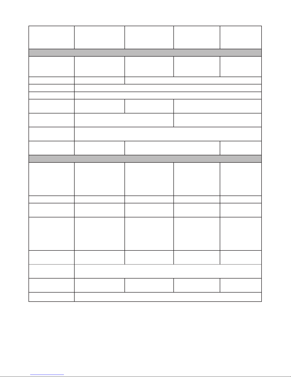
TURRET DOME AND LARGE BULLET CAMERAS
2MTD-2.8
(TURRET DOME)
4KB-MVF
(LARGE BULLET)
4MB-MVF
(LARGE
BULLET)
2MB-VF
(LARGE
BULLET)
GENERAL
IR Distance 30-50’ Night Vision
(1x Array IR LEDs)
131-165’ Night
Vision
(3xArray IR LEDs)
130-165’ Night
Vision
(IR Array LEDs)
130-165’ Night
Vision
3xIR-III LEDs)
Protection Grade / IP66
Power PoE with optional 12VDC
Power Jack 2.1mm Power Jack for optional 12VDC input
Power
Consumption
<6W <10W <9W
Operating Temp -14°F~122°F
(-9.7°C~50°C)
-4°F~131°F
(-15.5°C~55°C)
Operating
Humidity
0% - 90%
Dimensions
(inch)
3.28 (L) x 3.28 (W)
x 3.66 (H)
10.24 (L) x
3.07 (W) x 3.66 (H)
10.35 (L) x 3.66
(W) x 3.76 (H)
CAMERA
Image Sensor 1/2.9” SONY
2.07 MP
Progressive scan
Exmor
CMOS
1/2.5” 8MP
Progressive
scan CMOS
1/3” 4MP
progressive scan
CMOS
1/2.9” SONY
2.07 MP
Progressive
scan Exmor
CMOS
Effective Pixels 2MP ----- ----- 2MP
Max. Resolution 1920 x 1080 3840 x 2160 4MP (2592x1520) 1920 x 1080
Min. Illumination 0Lux/F1.4 (IR ON)
Color: 0.06Lux/
F1.4, B/W:
0.01Lux/F1.4
0Lux/F1.4 (IR on)
Color: 0.1Lux/
F1.4,
B/W: 0.5Lux/F1.4
0Lux/F1.4 (IR on)
Color: 0.5Lux/
F1.4,
B/W: 0.2Lux/F1.4
0Lux/F1.4 (IR
on)
Color: 0.06Lux/
F1.4, B/W:
0.01Lux/F1.4
Lens 2.8mm 3.0-10mm
motorized lens
2.8-12mm
motorized lens
2.8-12mm
varifocal lens
Electronic Shutter Auto/Manual
(1/25~1/10000), FLK
R/N Ratio ≥50db (AGC OFF) ----- ≥35db (AGC
OFF)
≥50db (AGC
OFF)
Output Model PAL/NTSC adjustable

22
SMALL BULLET CAMERAS
4MB-3.6
(SMALL BULLET)
2MB-3.6
SMALL BULLET
GENERAL
IR Distance 100’ Night Vision
(30 x Φ5 IR LEDs)
Protection Grade IP66
Power PoE for optional 12VDC
Power Jack 2.1mm Power Jack for
optional 12VDC input
Power
Consumption
<6W
Operating Temp -4°F~131°F
(-15.5°C~55°C)
Operating
Humidity
0% - 90%
Dimensions (inch) 2.6 (L) x 6.56 (W)
x 2.6 (H)
6.56 (L) x 2.6 (W)
x 2.6 (H) (compare to left)
CAMERA
Image Sensor 1/3” 4MP progressive
scan MOS
1/2.9” SONY 2.07 MP
Progressive scan Exmor
CMOS
Max. Resolution 4MP (2592 x 1520) 1920 x 1080
Min. Illumination 0Lux/F1.4 (IR on)
Color: 0.5Lux/F1.4,
B/W:0.2Lux/F1.4
0Lux/F1.4 (IR ON)
Color: 0.06Lux/F1.4,
B/W: 0.01Lux/F1.4
Lens 3.6mm
Electronic Shutter Auto/Manual
(1/25~1/10000), FLK
R/N Ratio ≥35db (AGC OFF) ≥50db (AGC OFF)
Output Model PAL/NTSC adjustable
COMPLIANCE
FCC PART 15
The equipment has been tested and found to comply with the limits for a Class B device, pursuant
to Part 15 of the FCC rules. These limits are designed to provide reasonable protection against
harmful interference in a residential installation. This equipment generates, uses, and can
radiate radio frequency energy and, if not installed and used in accordance with the instructions,
may cause harmful interference to radio communications. However, there is no guarantee
that interference will not occur in a particular installation. If this equipment does cause harmful
interference to radio or television reception, which can be determined by turning the equipment off
and on, the user is encouraged to try to correct the interference by one of the following measures:
• Reorient or relocate the receiving antenna.
• Increase the separation between the equipment and the receiver

23
• Connect the equipment into an outlet on a circuit different from that to which the receiver is
connected.
• Consult the dealer or an experienced radio/TV technician for help.
Changes or modications not expressly approved by the party responsible for compliance could
void your authority to operate the equipment. Any change or modication must be approved in
writing by Uniden.
This device complies with Part 15 of the FCC rules. Operation is subject to the following two
conditions: (1) This device may not cause harmful interference, and (2) this device must accept
any interference received, including interference that may cause undesired operation.
Tout changement ou modication non approuvé expressément par la partie responsable pourrait
annuler le droit à l’utilisateur de faire fonctionner cet équipement. Tout changement ou modication
doit être approuvé par écrit par Uniden.
Avis de conformité à la FCC : Ce dispositif a été testé et s’avère conforme à l’article 15 des
règlements de la Commission fédérale des communications (FCC). Ce dispositif est soumis
aux conditions suivantes: 1) Ce dispositif ne doit pas causer d’interférences nuisibles et; 2)
Il doit pouvoir supporter les parasites qu’il reçoit, incluant les parasites pouvant nuire à son
fonctionnement.
In order to comply with FCC RF Exposure requirements, this device must be installed to provide at
least 7.9 in (20 cm) separation from the human body at all times.
IC
This device complies with Industry Canada’s license-exempt RSSs. Operation is subject to the
following two conditions:
(1) this device may not cause interference, and
(2) this device must accept any interference, including interference that may cause undesired
operation of the device.
Cet appareil est conforme aux normes CNR d’Industrie Canada destinés aux appareils radio
exempts de licence. Son fonctionnement est soumis aux deux conditions suivantes :
1) Cet appareil ne doit pas causer d’interférences nuisibles et;
2) Il doit pouvoir accepter les interférences, incluant celles pouvant nuire à son fonctionnement
normal.
In order to comply with FCC/ISED RF Exposure requirements, this device must be installed to
provide at least 7.9 in. (20 cm) separation from the human body at all times.
An de se conformer aux exigences d’exposition RF FCC/ISED, ce dispositif doit être installé pour
assurer une séparation d’au moins 20 cm du corps humain à tout moment.
THREE-YEAR LIMITED WARRANTY
Important: SAVE YOUR RECEIPT! Evidence of original purchase is required for warranty service.
WARRANTOR: Uniden America Corporation (“Uniden”) ELEMENTS OF WARRANTY: Uniden warrants,
for three years, to the original retail owner, this Uniden Product to be free from defects in materials &
craftsmanship with only the limitations or exclusions set out below.
WARRANTY DURATION: This warranty to the original user shall terminate & be of no further effect 36
months after the date of original retail sale. The warranty is invalid if the Product is (A) damaged or not
maintained as reasonable or necessary, (B) modied, altered, or used as part of any conversion kits,
subassemblies, or any congurations not sold by Uniden, (C) improperly installed, (D) serviced or repaired

24
by someone other than an authorized Uniden service center for a defect or malfunction covered by this
warranty, (E) used in any conjunction with equipment or parts or as part of any system not manufactured
by Uniden, or (F) installed or programmed by anyone other than as detailed by the owner’s manual for this
product.
STATEMENT OF REMEDY: In the event that the product does not conform to this warranty at any time
while this warranty is in effect, warrantor will either, at its option, repair or replace the defective unit &
return it to you without charge for parts, service, or any other cost (except shipping & handling) incurred by
warrantor or its representatives in connection with the performance of this warranty. Warrantor, at its option,
may replace the unit with a new or refurbished unit.
THE LIMITED WARRANTY SET FORTH ABOVE IS THE SOLE & ENTIRE WARRANTY PERTAINING
TO THE PRODUCT & IS IN LIEU OF & EXCLUDES ALL OTHER WARRANTIES OF ANY NATURE
WHATSOEVER, WHETHER EXPRESS, IMPLIED OR ARISING BY OPERATION OF LAW, INCLUDING,
BUT NOT LIMITED TO ANY IMPLIED WARRANTIES OF MERCHANTABILITY OR FITNESS FOR
A PARTICULAR PURPOSE. THIS WARRANTY DOES NOT COVER OR PROVIDE FOR THE
REIMBURSEMENT OR PAYMENT OF INCIDENTAL OR CONSEQUENTIAL DAMAGES. Some states
do not allow this exclusion or limitation of incidental or consequential damages so the above limitation or
exclusion may not apply to you.
LEGAL REMEDIES: This warranty gives you specic legal rights, & you may also have other rights which
vary from state to state. This warranty is void outside the United States of America & Canada.
PROCEDURE FOR OBTAINING PERFORMANCE OF WARRANTY: If, after following the instructions in
the owner’s manual you are certain that the Product is defective, pack the Product carefully (preferably
in its original packaging). The Product should include all parts & accessories originally packaged with the
Product. Include evidence of original purchase & a note describing the defect that has caused you to return
it. The Product should be shipped freight prepaid, by traceable means, to warrantor at:
Uniden America Service
C/O Saddle Creek
743 Henrietta Creek Rd., Suite 100
Roanoke, TX 76026
 Loading...