

U-line ULNSP18FCB03A User Manual
USER GUIDE & SERVICE MANUAL
RIGHT PRODUCT. RIGHT PLACE. RIGHT TEMPERATURE. SINCE 1962.
SAFETY • INSTALLATION & INTEGRATION • OPERATING INSTRUCTIONS • MAINTENANCE • SERVICE
Marine Series • SP18 • 15" Crescent Ice Maker
USER GUIDE
u-line.com
Contents
SAFETY • INSTALLATION & INTEGRATION • OPERATING INSTRUCTIONS • MAINTENANCE • SERVICE
Intro
Safety
Safety and Warning
Disposal and Recycling
Installation
Environmental Requirements
Electrical
Cutout Dimensions
Product Dimensions
Water Hookup
General Installation
Integrated Panel Dimensions
Integrated Panel Installation
Grille / Plinth Installation
Troubleshooting
Warranty
Service Extended
Wire Diagram
Product Liability
Warranty Claims
Parts
Ordering Replacement Parts
System Diagnosis Guide
Compressor Specifications
Troubleshooting Extended
Defrost
Replace Ice Maker
Door Swing
Door Adjust
Door Latch
Operating Instructions
First Use
Ice
Airflow and Product Loading
Maintenance
Cleaning
Cleaning Condenser
Extended Non-Use
Service
USER GUIDE
u-line.com
WELCOME TO U-LINE
Congratulations on your U-Line purchase. Your product comes from a company with over five decades of premium modular
ice making, refrigeration, and wine preservation experience. U-Line continues to be the American leader, delivering versatility
and flexibility for multiple applications including residential, light commercial, outdoor and marine use. U-Line’s complete
product collection includes Wine Captain
Door Refrigerators, Drawer Models, Freezers, Combo® Models, and more.
U-Line has captivated those with an appreciation for the finer things with exceptional functionality, style, inspired innovations
and attention to even the smallest details. We are known and respected for our unwavering dedication to product design,
quality and selection. U-Line is headquartered in Milwaukee, Wisconsin and has shipped product to five continents for over
two decades and is proud to have the opportunity to ship to you.
PRODUCT INFORMATION
Looking for additional information on your product? User Guides, Spec Sheets, CAD Drawings, Compliance Documentation,
and Product Warranty information are all available for reference and download at u-line.com.
®
Models, Beverage Centers, Clear Ice Machines, Crescent Ice Makers, Glass & Solid
PROPERTY DAMAGE / INJURY CONCERNS
In the unlikely event property damage or personal injury is suspected related to a U-Line product, please take the following
steps:
1. U-Line Customer Care must be contacted immediately at +1.800.779.2547.
2. Service or repairs performed on the unit without prior written approval from U-Line is not permitted. If the unit has been
altered or repaired in the field without prior written approval from U-Line, claims will not be eligible.
GENERAL INQUIRIES
U-Line Corporation
8900 N. 55th Street
Milwaukee, Wisconsin 53223 USA
Monday - Friday 8:00 am to 4:30 pm CST
T: +1.414.354.0300
F: +1.414.354.7905
Email: sales@u-line.com
u-line.com
SERVICE & PARTS ASSISTANCE
Monday - Friday 8:00 am to 4:30 pm CST
T: +1.800.779.2547
F: +1.414.354.5696
Service Email: onlineservice@u-line.com
Parts Email: onlineparts@u-line.com
CONNECT WITH US
Designed, engineered and assembled in WI, USA
Introduction 1
USER GUIDE
NOTICE
u-line.com
SAFETY • INSTALLATION & INTEGRATION • OPERATING INSTRUCTIONS • MAINTENANCE • SERVICE
Safety and Warning
Please read all instructions before installing,
operating, or servicing the appliance.
Use this appliance for its intended purpose only and follow
these general precautions with those listed throughout this
guide:
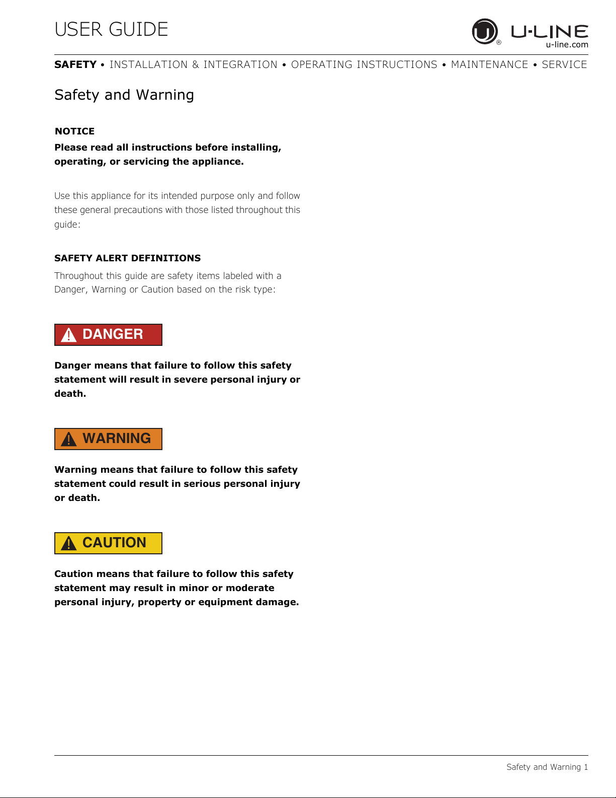
SAFETY ALERT DEFINITIONS
Throughout this guide are safety items labeled with a
Danger, Warning or Caution based on the risk type:
DANGER
!
Danger means that failure to follow this safety
statement will result in severe personal injury or
death.
WARNING
!
Warning means that failure to follow this safety
statement could result in serious personal injury
or death.
CAUTION
!
Caution means that failure to follow this safety
statement may result in minor or moderate
personal injury, property or equipment damage.
Safety and Warning 1
USER GUIDE
u-line.com
SAFETY • INSTALLATION & INTEGRATION • OPERATING INSTRUCTIONS • MAINTENANCE • SERVICE
Disposal and Recycling
DANGER
!
RISK OF CHILD ENTRAPMENT. Before you throw
away your old refrigerator or freezer, take off
the doors and leave shelves in place so children
may not easily climb inside.
If the unit is being removed from service for disposal,
check and obey all federal, state and local regulations
regarding the disposal and recycling of refrigeration
appliances, and follow these steps completely:
1. Remove all consumable contents from the unit.
2. Unplug the electrical cord from its socket.
3. Remove the door(s)/drawer(s).
Disposal and Recycling 1
USER GUIDE
u-line.com
SAFETY • INSTALLATION & INTEGRATION • OPERATING INSTRUCTIONS • MAINTENANCE • SERVICE
Environmental Requirements
This model is intended for indoor/interior applications only
and is not to be used in installations that are open/
exposed to natural elements.
This unit is designed to operate between 50°F (10°C) and
100°F (38°C). Higher ambient temperatures may reduce
the unit’s ability to reach low temperatures and/or reduce
ice production on applicable models.
For best performance, keep the unit out of direct sunlight
and away from heat generating equipment.
In climates where high humidity and dew points are
present, condensation may appear on outside surfaces.
This is considered normal. The condensation will
evaporate when the humidity drops.
CAUTION
!
Damages caused by ambient temperatures of
40°F (4°C) or below are not covered by the
warranty.
Environmental Requirements 1
USER GUIDE
NOTICE
u-line.com
SAFETY • INSTALLATION & INTEGRATION • OPERATING INSTRUCTIONS • MAINTENANCE • SERVICE
Electrical
WARNING
!
SHOCK HAZARD — Electrical Grounding
Required. Never attempt to repair or perform
maintenance on the unit until the electricity has
been disconnected.
Never remove the round grounding prong from
the plug and never use a two-prong grounding
adapter.
Altering, cutting or removing power cord,
removing power plug, or direct wiring can cause
serious injury, fire, loss of property and/or life,
and will void the warranty.
Never use an extension cord to connect power to
the unit.
Always keep your working area dry.
Electrical installation must observe all state and
local codes. This unit requires connection to a
grounded (three-prong), polarized receptacle
that has been placed by a qualified electrician.
The unit requires a grounded and polarized 115 VAC,
60 Hz, 15A power supply (normal household current). An
individual, properly grounded branch circuit or circuit
breaker is recommended. A GFCI (ground fault circuit
interrupter) is usually not required for fixed location
appliances and is not recommended for your unit because
it could be prone to nuisance tripping. However, be sure
to consult your local codes.
See CUTOUT DIMENSIONS for recommended receptacle
location.
Electrical 1
USER GUIDE
NOTICE
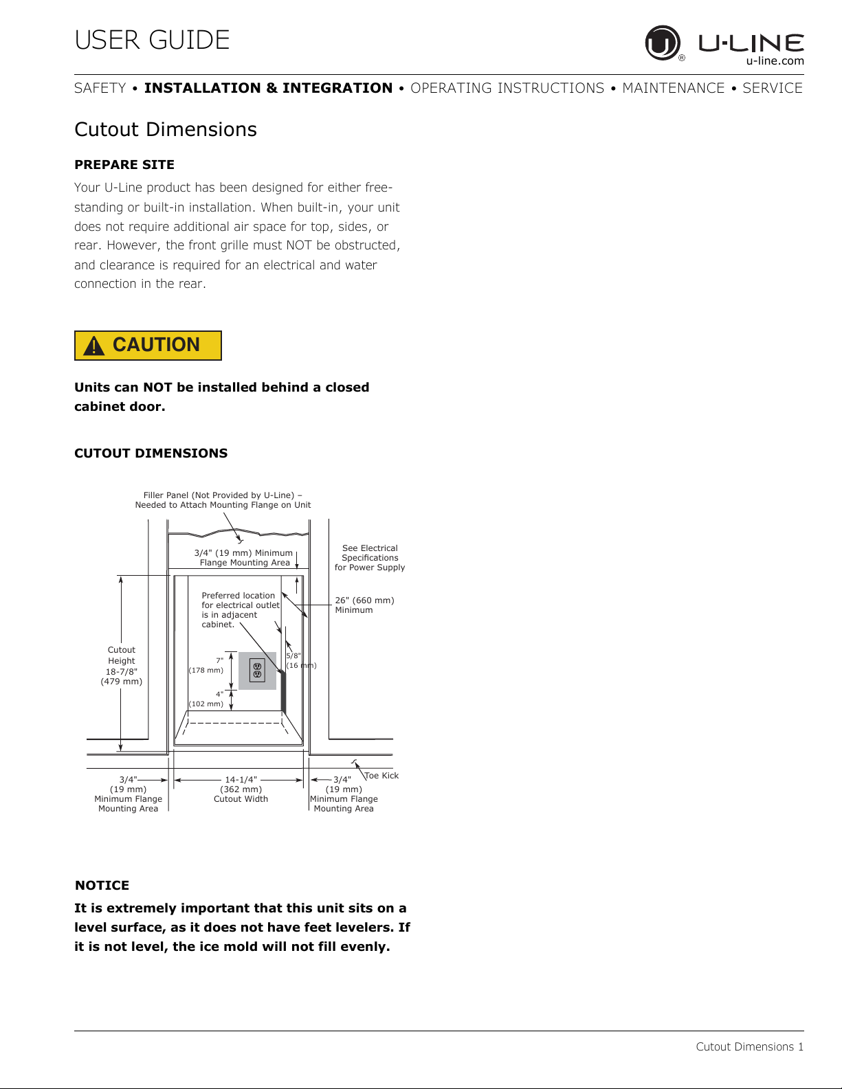
Cutout
Height
18-7/8"
(479 mm)
26" (660 mm)
Minimum
See Electrical
6SHFLɟFDWLRQV
for Power Supply
Filler Panel (Not Provided by U-Line) –
Needed to Attach Mounting Flange on Unit
Toe Kick
14-1/4"
(362 mm)
Cutout Width
3/4"
(19 mm)
Minimum Flange
Mounting Area
3/4" (19 mm) Minimum
Flange Mounting Area
3/4"
(19 mm)
Minimum Flange
Mounting Area
4"
(102 mm)
7"
(178 mm)
Preferred location
for electrical outlet
LVLQDGMDFHQW
cabinet.
5/8"
(16 mm)
u-line.com
SAFETY • INSTALLATION & INTEGRATION • OPERATING INSTRUCTIONS • MAINTENANCE • SERVICE
Cutout Dimensions
PREPARE SITE
Your U-Line product has been designed for either free-
standing or built-in installation. When built-in, your unit
does not require additional air space for top, sides, or
rear. However, the front grille must NOT be obstructed,
and clearance is required for an electrical and water
connection in the rear.
CAUTION
!
Units can NOT be installed behind a closed
cabinet door.
CUTOUT DIMENSIONS
It is extremely important that this unit sits on a
level surface, as it does not have feet levelers. If
it is not level, the ice mold will not fill evenly.
Cutout Dimensions 1
USER GUIDE
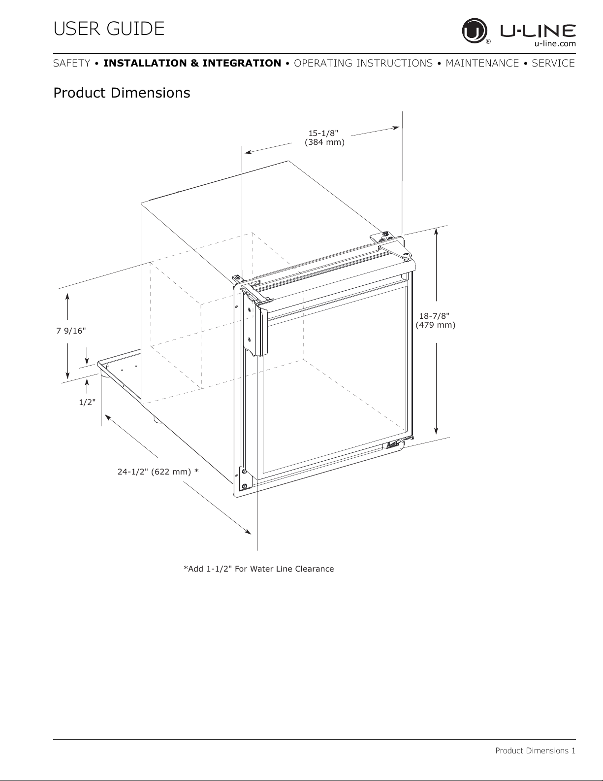
15-1/8"
(384 mm)
24-1/2" (622 mm) *
18-7/8"
(479 mm)
7 9/16"
1/2"
*Add 1-1/2" For Water Line Clearance
u-line.com
SAFETY • INSTALLATION & INTEGRATION • OPERATING INSTRUCTIONS • MAINTENANCE • SERVICE
Product Dimensions
Product Dimensions 1
USER GUIDE
u-line.com
SAFETY • INSTALLATION & INTEGRATION • OPERATING INSTRUCTIONS • MAINTENANCE • SERVICE
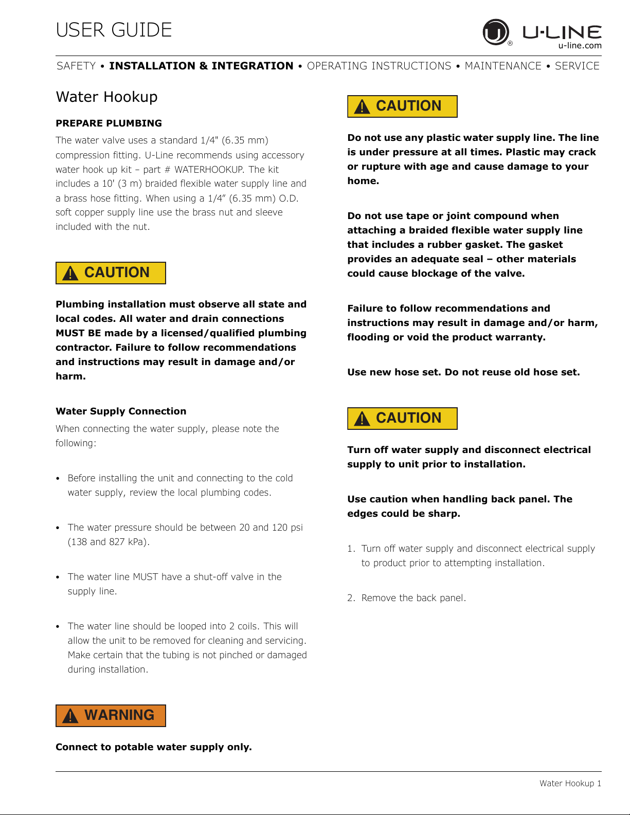
Water Hookup
PREPARE PLUMBING
The water valve uses a standard 1/4" (6.35 mm)
compression fitting. U-Line recommends using accessory
water hook up kit – part # WATERHOOKUP. The kit
includes a 10' (3 m) braided flexible water supply line and
a brass hose fitting. When using a 1/4” (6.35 mm) O.D.
soft copper supply line use the brass nut and sleeve
included with the nut.
CAUTION
!
Plumbing installation must observe all state and
local codes. All water and drain connections
MUST BE made by a licensed/qualified plumbing
contractor. Failure to follow recommendations
and instructions may result in damage and/or
harm.
CAUTION
!
Do not use any plastic water supply line. The line
is under pressure at all times. Plastic may crack
or rupture with age and cause damage to your
home.
Do not use tape or joint compound when
attaching a braided flexible water supply line
that includes a rubber gasket. The gasket
provides an adequate seal – other materials
could cause blockage of the valve.
Failure to follow recommendations and
instructions may result in damage and/or harm,
flooding or void the product warranty.
Use new hose set. Do not reuse old hose set.
Water Supply Connection
When connecting the water supply, please note the
following:
• Before installing the unit and connecting to the cold
water supply, review the local plumbing codes.
• The water pressure should be between 20 and 120 psi
(138 and 827 kPa).
• The water line MUST have a shut-off valve in the
supply line.
• The water line should be looped into 2 coils. This will
allow the unit to be removed for cleaning and servicing.
Make certain that the tubing is not pinched or damaged
during installation.
CAUTION
!
Turn off water supply and disconnect electrical
supply to unit prior to installation.
Use caution when handling back panel. The
edges could be sharp.
1. Turn off water supply and disconnect electrical supply
to product prior to attempting installation.
2. Remove the back panel.
WARNING
!
Connect to potable water supply only.
Water Hookup 1
USER GUIDE
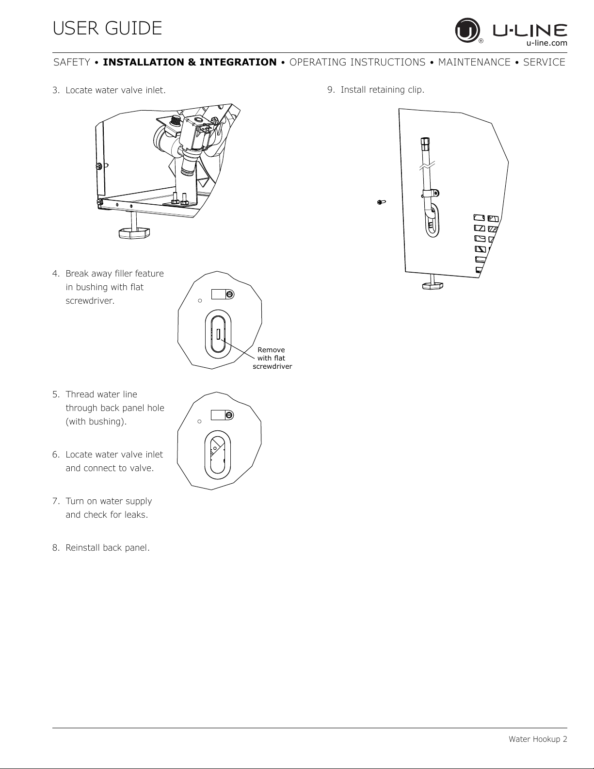
Remove
ZLWKɠDW
screwdriver
u-line.com
SAFETY • INSTALLATION & INTEGRATION • OPERATING INSTRUCTIONS • MAINTENANCE • SERVICE
3. Locate water valve inlet.
4. Break away filler feature
in bushing with flat
screwdriver.
9. Install retaining clip.
5. Thread water line
through back panel hole
(with bushing).
6. Locate water valve inlet
and connect to valve.
7. Turn on water supply
and check for leaks.
8. Reinstall back panel.
Water Hookup 2
USER GUIDE
NOTICE
1
u-line.com
SAFETY • INSTALLATION & INTEGRATION • OPERATING INSTRUCTIONS • MAINTENANCE • SERVICE
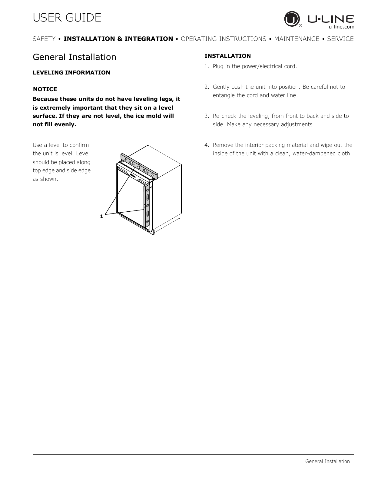
General Installation
LEVELING INFORMATION
Because these units do not have leveling legs, it
is extremely important that they sit on a level
surface. If they are not level, the ice mold will
not fill evenly.
Use a level to confirm
the unit is level. Level
should be placed along
top edge and side edge
as shown.
INSTALLATION
1. Plug in the power/electrical cord.
2. Gently push the unit into position. Be careful not to
entangle the cord and water line.
3. Re-check the leveling, from front to back and side to
side. Make any necessary adjustments.
4. Remove the interior packing material and wipe out the
inside of the unit with a clean, water-dampened cloth.
General Installation 1
USER GUIDE
NOTICE
u-line.com
SAFETY • INSTALLATION & INTEGRATION • OPERATING INSTRUCTIONS • MAINTENANCE • SERVICE
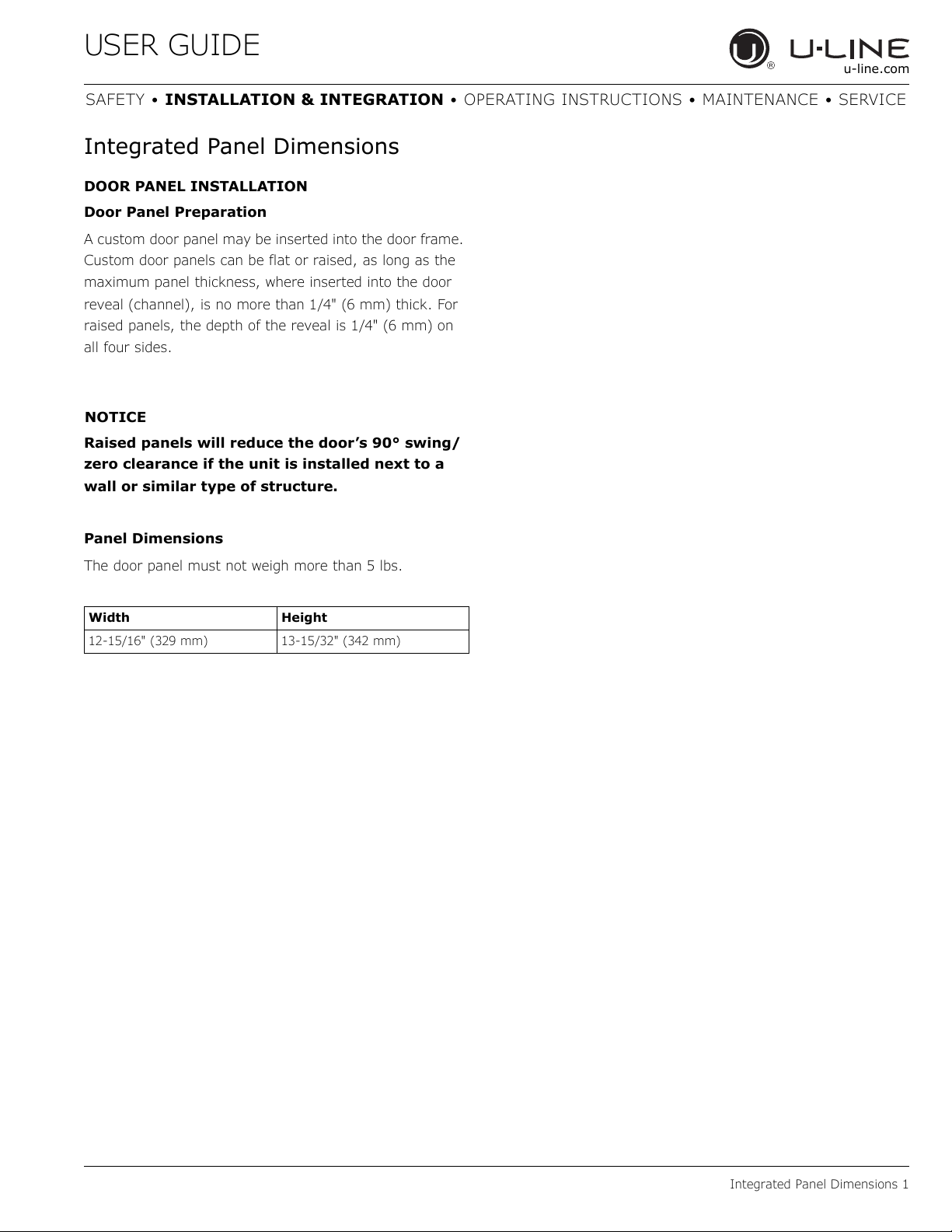
Integrated Panel Dimensions
DOOR PANEL INSTALLATION
Door Panel Preparation
A custom door panel may be inserted into the door frame.
Custom door panels can be flat or raised, as long as the
maximum panel thickness, where inserted into the door
reveal (channel), is no more than 1/4" (6 mm) thick. For
raised panels, the depth of the reveal is 1/4" (6 mm) on
all four sides.
Raised panels will reduce the door’s 90° swing/
zero clearance if the unit is installed next to a
wall or similar type of structure.
Panel Dimensions
The door panel must not weigh more than 5 lbs.
Width Height
12-15/16" (329 mm) 13-15/32" (342 mm)
Integrated Panel Dimensions 1
USER GUIDE
u-line.com
SAFETY • INSTALLATION & INTEGRATION • OPERATING INSTRUCTIONS • MAINTENANCE • SERVICE
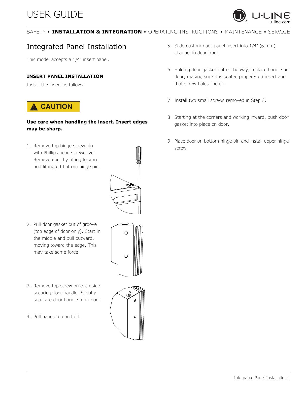
Integrated Panel Installation
This model accepts a 1/4" insert panel.
INSERT PANEL INSTALLATION
Install the insert as follows:
CAUTION
!
Use care when handling the insert. Insert edges
may be sharp.
1. Remove top hinge screw pin
with Phillips head screwdriver.
Remove door by tilting forward
and lifting off bottom hinge pin.
5. Slide custom door panel insert into 1/4" (6 mm)
channel in door front.
6. Holding door gasket out of the way, replace handle on
door, making sure it is seated properly on insert and
that screw holes line up.
7. Install two small screws removed in Step 3.
8. Starting at the corners and working inward, push door
gasket into place on door.
9. Place door on bottom hinge pin and install upper hinge
screw.
2. Pull door gasket out of groove
(top edge of door only). Start in
the middle and pull outward,
moving toward the edge. This
may take some force.
3. Remove top screw on each side
securing door handle. Slightly
separate door handle from door.
4. Pull handle up and off.
Integrated Panel Installation 1
USER GUIDE
1
2
u-line.com
SAFETY • INSTALLATION & INTEGRATION • OPERATING INSTRUCTIONS • MAINTENANCE • SERVICE
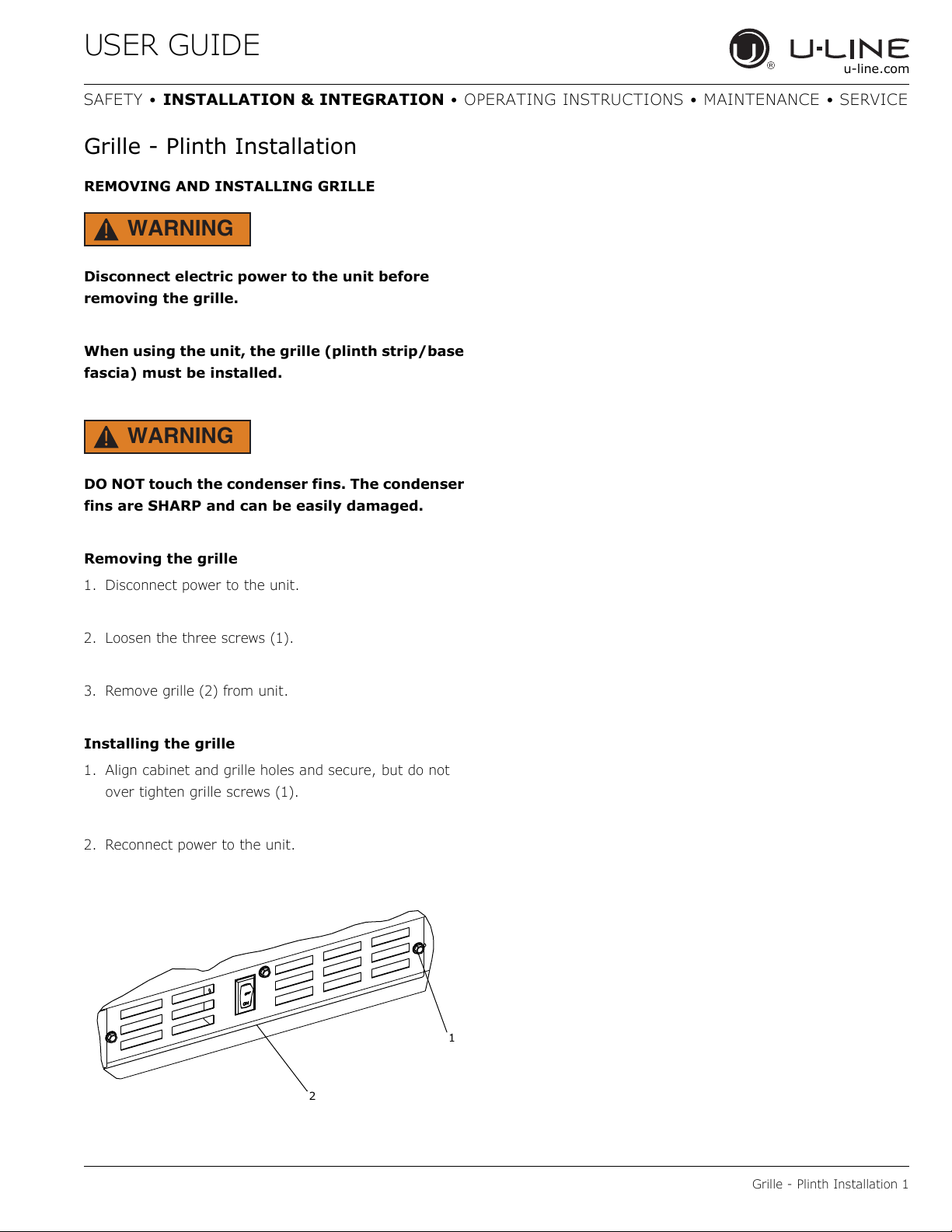
Grille - Plinth Installation
REMOVING AND INSTALLING GRILLE
WARNING
!
Disconnect electric power to the unit before
removing the grille.
When using the unit, the grille (plinth strip/base
fascia) must be installed.
WARNING
!
DO NOT touch the condenser fins. The condenser
fins are SHARP and can be easily damaged.
Removing the grille
1. Disconnect power to the unit.
2. Loosen the three screws (1).
3. Remove grille (2) from unit.
Installing the grille
1. Align cabinet and grille holes and secure, but do not
over tighten grille screws (1).
2. Reconnect power to the unit.
Grille - Plinth Installation 1
USER GUIDE
3/4" (19 mm) Min.
Wall
90°
Door Swing
u-line.com
SAFETY • INSTALLATION & INTEGRATION • OPERATING INSTRUCTIONS • MAINTENANCE • SERVICE
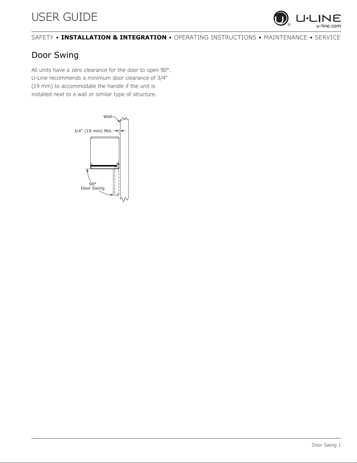
Door Swing
All units have a zero clearance for the door to open 90°.
U-Line recommends a minimum door clearance of 3/4"
(19 mm) to accommodate the handle if the unit is
installed next to a wall or similar type of structure.
Door Swing 1
 Loading...