

U-Line U-CLR2160B-00, U-CLR2160W-40, U-CO1175S-00, U-CO29B-20, U-CLR2160B-40 Installation Guide
...
®
INSTALL GUIDE
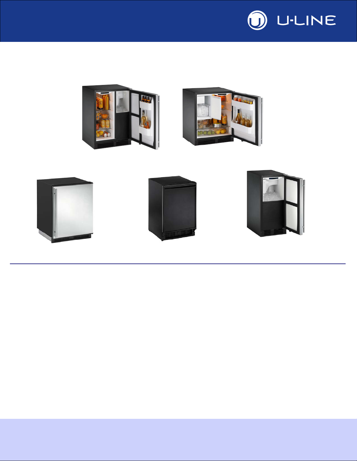
CLEAR ICE MODELS
CLEAR ICE COMBO MODELS
ICE COMBO MODELS
CO1175
CO2175
CO29
CLRCO2175
CLR2160
Models Covered
• U-CLR2160B-00 • U-CLR2160W-40 • U-CO1175S-00 • U-CO29B-20
• U-CLR2160B-40 • U-CLR2160W-40 • U-CO1175S-01 • U-CO29BTP-20
• U-CLR2160S-00 • U-CLRCO2175B-00 • U-CO1175S-20 • U-CO29FB-00
• U-CLR2160S-01 • U-CLRCO2175B-40 • U-CO1175S-22 • U-CO29FB-98
• U-CLR2160S-40 • U-CLRCO2175S-00 • U-CO2175FB-00 • U-CO29FB-99
• U-CLR2160S-41 • U-CLRCO2175S-01 • U-CO2175FS-00 • U-CO29FWH-00
• U-CLR2160SOD-00 • U-CLRCO2175S-40 • U-CO2175FS-01 • U-CO29WH-03
• U-CLR2160SOD-01 • U-CLRCO2175S-41 • U-CO2175FW-00 • U-CO29WHTP-20
• U-CLR2160SOD-40 • U-CO1175B-00 • U-CO29B-00
• U-CLR2160SOD-41 • U-CO1175B-20 • U-CO29B-03
The American Built-In Undercounter Leader Since 1962
U-LINE.COM

1 Table of Contents
Safety Precautions
Safety Alert Definitions.........................................................................................................................................1
General Precautions..............................................................................................................................................1
Inspect & Plan
Product Registration .............................................................................................................................................2
Product Description..............................................................................................................................................2
Tools / Material Required ....................................................................................................................................2
Exterior Cleaning ...................................................................................................................................................2
Black and White Models:........................................................................................................................... 2
Stainless Models:.......................................................................................................................................... 2
Prepare Site
Cut-Out Dimensions.............................................................................................................................................3
(CLR)CO21 & CO11 Series..................................................................................................................... 3
CLR2160 Series........................................................................................................................................... 3
CO29 Series................................................................................................................................................. 3
Product Dimensions
All Models................................................................................................................................................................4
Door Swing Dimensions
Other Site Requirements.....................................................................................................................................5
Side-By-Side Installation............................................................................................................................. 5
Power Supply ............................................................................................................................................... 5
Water Supply ............................................................................................................................................... 5
Drain .............................................................................................................................................................. 5
Standard Doors
Doors (Self Closing)
Door Panel Installation
Wood Grille Overlay
Prepare Power Supply
Prepare Plumbing
Level The Unit
Install the Unit
Environmental Requirements................................................................................................................... 5
Door Alignment and Adjustment.......................................................................................................................6
Door Reversability.................................................................................................................................................6
Reversing the Door...............................................................................................................................................6
Door Alignment and Adjustment.......................................................................................................................8
Door Reversability.................................................................................................................................................8
Reversing Black or White Doors.......................................................................................................................9
Reversing Stainless Steel Glass Doors 10
Custom 1/4'' Thick Door Panel Insert............................................................................................................13
Door Panel Preparation.......................................................................................................................... 13
Panel Dimensions..................................................................................................................................... 13
Door Panel Installation ........................................................................................................................... 13
Grille Overlay (Excludes CO1175)..................................................................................................................14
Preparation................................................................................................................................................ 14
Installation.................................................................................................................................................. 14
Electrical Specifications.......................................................................................................................................17
Receptacle Location ............................................................................................................................................17
Copper Water Supply Connection:.................................................................................................................18
U-Line Water Hookup Kit Connection:.........................................................................................................19
Gravity Drain: .......................................................................................................................................................19
Factory Installed Drain Pump............................................................................................................................20
Drain Connection: ...............................................................................................................................................21
Final Installation 21
Leveling Information............................................................................................................................................22
Installation..............................................................................................................................................................22
Relocating the Shelves............................................................................................................................. 22
Installation Troubleshooting.................................................................................................................. 23
IMPORTANTIMPORTANT
DANGER
WARN ING
CAUTION
2 Safety Precautions
DANGER
WARN ING
WARN ING
CAUTION
IMPORTANTIMPORTANT
• PLEASE READ all instructions before installing,
operating, or servicing the appliance.
General Precautions
Use this appliance for its intended purpose only. Follow these
general precautions with those listed throughout this guide:
• Proper installation procedures must be followed when
completing an installation or relocation of a unit.
Consult the installation guide before any installation
begins. U-Line contact information appears on the rear
cover of this guide.
• This unit requires connection to a dedicated 15 Amp
grounded (three-prong), polarized receptacle, installed
by a qualified electrician, compliant with applicable
electrical codes.
Safety Alert Definitions
Throughout this guide are safety items labeled with a Danger,
Warning or Caution based on the risk type:
Danger means that failure to follow this safety statement will
result in severe personal injury or death.
Warning means that failure to follow this safety
statement could result in serious personal injury,
property or equipment damage.
RISK OF CHILD ENTRAPMENT. Before you throw away your
old refrigerator or freezer, take off the doors and leave shelves
in place so children may not easily climb inside.
SHOCK HAZARD - Electrical Grounding Required.
• Never attempt to repair or perform maintenance on
the unit until the electricity has been disconnected.
• Never remove the round grounding prong from the
plug and never use a two-prong grounding adapter.
• Altering, cutting of power cord, removal of power
cord, removal of power plug, or direct wiring can
cause serious injury, fire and or loss of property and
or life, and will void the warranty.
• Never use an extension cord to connect power to the
unit.
• Always keep your working area dry.
Install provided Anti-Tip kit. Serious personal
injury could occur.
• Use care when moving and handling the unit. Use gloves
to prevent personal injury from sharp edges.
• If your model requires defrosting, DO NOT use an ice
pick or other sharp instrument to help speed up
defrosting. These instruments can puncture the inner
lining or damage the cooling unit. DO NOT use any type
of heater to defrost. Using a heater to speed up
defrosting can cause personal injury and damage to the
inner lining.
Caution means that failure to follow this safety statement
may result in minor or moderate personal injury, property
or equipment damage.
Precautions 1
• Do not lift unit by door handle.
• Never install or operate the unit behind closed doors.
Be sure front grille is free of obstruction. Obstructing
free airflow can cause the unit to malfunction and will
void the warranty.
• Failure to clean the condenser every six months can
cause the unit to malfunction. This could void the
warranty.
• Allow unit temperature to stabilize for 24 hours before
use.
• Do not Block any internal Fans
Use only genuine U-Line replacement parts. Imitation
parts can damage the unit, affect its operation or
performance and may void the warranty.
3 Inspect & Plan
WARN ING
Product Registration
You have received a carton containing your U-Line Clear Ice, Ice or
Ice Combo unit with a package inside containing a Use and Care
Guide, a Product Registration Card, and a water line kit. Please
complete and mail the Product Registration Card or register online
at www.U-LineService.com. Once your unit is installed, keep the
Use and Care Guide and this Installation Guide in a safe place for
future reference.
Product Description
This installation guide covers the following models.
U-CLR2160B-00 U-CLRCO2175S-00
U-CLR2160B-40 U-CLRCO2175S-01
U-CLR2160S-00 U-CLRCO2175S-40
U-CLR2160S-01 U-CLRCO2175S-41
U-CLR2160S-40 U-CO1175B-00
U-CLR2160S-41 U-CO1175S-00
U-CLR2160SOD-00 U-CO1175S-01
U-CLR2160SOD-01 U-CO2175FB-00
U-CLR2160SOD-40 U-CO2175FS-00
U-CLR2160SOD-41 U-CO2175FS-01
U-CLR2160W-00 U-CO2175FW-00
U-CLR2160W-40 U-CO29B-00
U-CLRCO2175B-00 U-CO29FB-00
U-CLRCO2175B-40 U-CO29FWH-00
Inspection
Unwrap and inspect the unit on a flat, level surface capable of
supporting it’s entire weight. If necessary remove protective film
from Stainless Steel models.
Tools / Material Required
• Screwdrivers — slotted, Phillips head
• 1/4-inch thick door panel material and cutting tools (If installing
a 1/4” Panel)
• 1/4” Nut Driver
• 5/16” Nut Driver
• Side Cutter
• Copper tubing cutter
• 12” Level
• 9/16” Open end wrench
• 7/16” Open end wrench
• Pliers
• Copper tubing
CO2175 Models Only
• Full Overlay Door Panel Kit. Part number U-OL2175B (black
units) U-OL2175W (white units)
A complete water hook up kit is also available for purchase from
your dealer. Order U-Line Part No. WATERHOOKUP.
Exterior Cleaning
Black and White Models:
• Black and White surfaces may be cleaned with a mild detergent
and warm water solution. Do not use solvent-based or abrasive
cleaners. Use a soft sponge and rinse with clean water. Wipe
with a soft, clean towel to prevent water spotting.
Stainless Models:
• Stainless door panels, handles and frames can discolor when
exposed to chlorine gas, pool chemicals, salt water or cleaners
with bleach.
• Keep your Stainless unit looking new by cleaning with a good
quality all-in-one stainless steel cleaner/polish on a monthly
basis. For best results use Claire Stainless Steel Polish and
Cleaner, which can be purchased from U-Line Corporation
(Part numbers 173348). Frequent cleaning will remove surface
contamination that could lead to rust. Some installations may
require cleaning on a weekly basis.
• Do not clean with steel wool or abrasive pads.
• Do not use cleaners that are not specifically intended
for stainless steel on stainless surfaces (this includes
glass, tile and counter cleaners).
• If any surface discolors or rust appears, clean it quickly with
Bon-Ami or Barkeepers Friend Cleanser and a non-abrasive
cloth. Always clean in the direction of the grain. Always finish
this process with Claire Stainless Steel Polish and Cleaner or
comparable product to prevent further problems.
Rust that is allowed to linger can penetrate into the
surface of the stainless steel and complete removal of
the rust may not be possible.
2 U-Line Product Features
4 Prepare Site
IMPORTANTIMPORTANT
8"
24"
Minimum
24-1/4"
See Electrical
Specifications
for Power Supply
34-1/4"
to
35-1/8"
See Electrical
Specifications
for Power Supply
34-1/4"
to
35-1/8"
15-1/4"
8"
24"
IMPORTANTIMPORTANT
8"
24"
Minimum
21-1/16"
See Electrical
Specifications
for Power Supply
Typical
Counter
Height
34-1/4"
to
35-1/8"
Cut-Out
Height
28-5/8"
to
28-7/8"
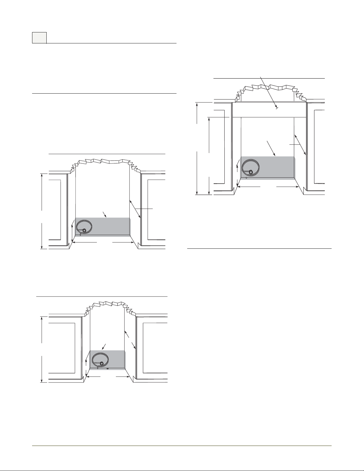
Filler Panel (Not Provided by U-Line) –
May Be Added Above or Below Unit
to Enclose for a Built-In Look
Your U-Line product has been designed for either free-standing or
built-in installation. When built-in, your unit does not require
additional air space for top, sides, or rear. However, the front grille
must NOT be obstructed and clearance is required for an
electrical connection in the rear.
• Unit can NOT be installed behind a closed cabinet door.
• If you would like to align the face of the unit with other adjacent
cabinet doors, you may need to alter the wall just behind the
drain connection on the unit to accommodate the drain.
Cut-Out Dimensions
(CLR)CO21 & CO11 Series
CO29 Series
Follow the cut-out drawing. The 21-1/16" width allows 1/4" for
ease in installation and removal of the unit. 24" is the counter
depth in most installations. The unit is 24" deep including the door
and handle.
Follow the cut-out drawing. The 24-1/4" width allows 1/4" for ease
in installation and removal of the unit. 24" is the cabinet depth in
most installations.
CLR2160 Series
Follow the cut-out drawing The 15-1/4" width allows 1/4" for ease
in installation and removal of the unit. 24" is the cabinet depth in
most installations.
It is extremely important that this unit sits on a level
surface, as it does not have feet levelers. If it is not level,
the ice mold will not fill evenly.
Prepare Site 3
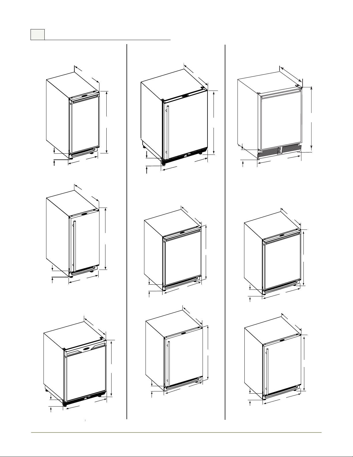
5 Product Dimensions
23” *
28-1/2"
20-13/16"
*Add 15/16” To Depth For Water Line Clearance
4-3/4”
34-1//8"
24"
Black and White
Stainless Steel
34-1/8"
24”
3-13/16”
3-13/16”
23”
23”
*Add 3/4” To Depth For Water Line Clearance
*Add 3/4” To Depth For Water Line Clearance
34-1/8"
34-1/8"
15"
15"
Black and White
Stainless Steel
23-3/16" *
3-7/8”
23-1/8” *
3-15/16”
*Add 3/4” To Depth For Drain Line Clearance
*Add 3/4” To Depth For Drain Line Clearance
BLACK CO1175
23-1/4" *
34-1/8"
23-15/16”"
*Add 3/16” to Depth For Water Line Clearance
3-1/2”
34-1/8"
23-15/16”"
STAINLESS CO1175
23-1/16”*
*Add 3/16” to Depth For Water Line Clearance
3-1/2”
34-1/8”
24"
Black and White
Stainless Steel
34-1/8"
24"
3-13/16”
23”*
23”*
3-13/16”
*Add 3/16” To Depth For Water Line Clearance
*Add 3/16” To Depth For Water Line Clearance
CLR2160 Series CO1175 Series CO29 Series
All Models
CO1175 Series
CO2175 Series
CLRCO2175 Series
4 Product Dimensions
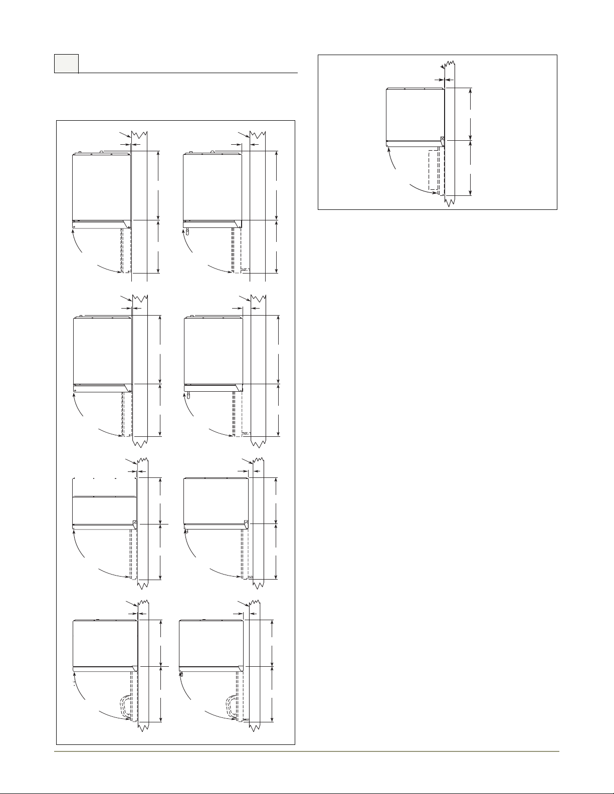
6 Door Swing Dimensions
1/4" Min.
Wall
21-3/4"
Wall
16-1/2"
21-3/4"
16-1/2"
2-1/8" Min.
90
Door Swing
90
Door Swing
Black and White Stainless Steel
CLR2160
1/4" Min.
Wall
21-3/4"
Wall
21-3/4"
25-1/2" 25-1/2"
2-1/8" Min.
90
Door Swing
90
Door Swing
Black and White Stainless Steel
CLRCO2160
1/4" Min.
Wall
90
Door Swing
20-7/8"
25-1/2"
Black
Wall
2" Min.
90
Door Swing
20-7/8"
25-1/4"
Stainless
CO1175
1/4" Min.
Wall
Wall
2-1/8" Min.
90
Door Swing
Black and White Stainless Steel
90
Door Swing
21-7/16"
25-1/2"
21-7/16"
25-1/2"
CO2175
1/4" Min.
90°
Door Swing
21-7/16"
22-3/8"
CO29
All units have a zero clearance for the door to open 90°. U-Line
recommends a minimum door clearance of 2” to accommodate
the handle if the unit is installed next to a wall.
Other Site Requirements
Side-By-Side Installation
For a complete refreshment center, install two units side by side:
Cut-out width for a side-by-side installation is the total of the
widths listed under Cut-Out Dimensions in each unit’s Installation
Guide.
No trim kit is required. However, 1/4-inch space needs to be
maintained between the units to ensure unobstructed door swing.
Units must operate from separate, properly grounded electrical
receptacles placed according to each unit’s Electrical Specifications
Requirements
Power Supply
The unit requires a grounded and polarized 115 VAC, 60 Hz, 15A
circuit (normal household current). See Electrical Specifications.
Water Supply
The unit requires a 1/4” O.D. soft copper supply line, or flexible
water supply kit from U-Line (Part No. WATERHOOKUP).
Drain
The CLR2160 & CLRCO2175 require access to either a gravity or
pump fed drain.
Environmental Requirements
The units are designed to operate between 50°F (10°C) and 100°F
(37°C). High ambient temperatures (100°F [37°C] or higher) may
reduce the unit’s ability to reach low temperatures and may also
reduce the ice production rate for those models with ice makers.
If the ambient temperature is expected to drop below 45°F (7°C),
drain all water from the unit to prevent freezing damage, which is
not covered by the warranty.
For best performance, keep the unit out of direct sunlight and away
from heat generating equipment.
In climates where high humidity and dew points are present,
condensation may appear on outside surfaces. This is considered
normal. The condensation will evaporate when the humidity drops.
CLR2160SOD Models: For best performance and life outdoors,
place under a counter or provide shelter of some kind.
Door Swing Dimensions 5
General Information
NOTICE
Plastic
Plug Hole
Plastic
Plug Hole
Right Side
Door Swing
Left Side
Door Swing
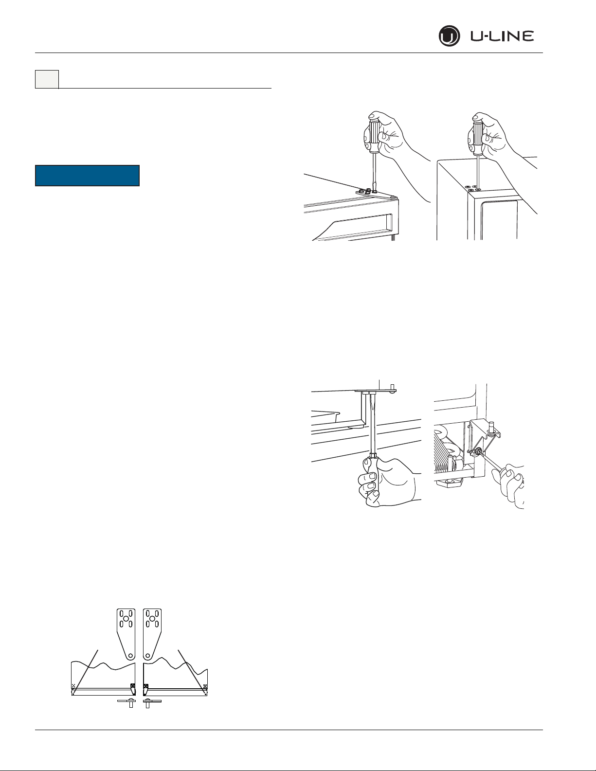
7 Standard Doors
Door Alignment and Adjustment
Align and adjust the door if it is not level, or is not sealing properly. If
the door is not sealed the unit may not cool properly, or excessive
frost may form in the interior.
Properly aligned, the door’s gasket should be firmly in
contact with the cabinet all the way around the door (no
gaps). Carefully examine the door’s gasket to assure that it is
firmly in contact with the cabinet. Also make sure the door
gasket is not pinched on the hinge side of the door.
To align and adjust the door.
1. Loosen (do not remove) top and bottom hinge screws.
2. Align door squarely with cabinet.
3. Make sure gasket is firmly in contact with cabinet all the way around the door (no gaps).
4. Tighten bottom hinge screws.
5. Tighten top hinge screws.
Door Reversability
Remove grille.
Remove the grille, see MAINTENANCE section of this guide.
Remove top hinge, and door.
1. Hold door to keep it from falling.
2. Remove top hinge from cabinet by removing three or four screws, depending on model.
3. Remove door by tilting forward and lifting door off bottom hinge.
4. Remove three or four plastic screw plugs from hinge holes on the opposite side. Reinstall into holes where the hinge was removed. Ensure not to scratch cabinet.
(Does not apply to ADA or lock units)
Location of the unit may make it desirable to mount the door on the
opposite side of the cabinet.
Models with black and white doors are field-reversible.
Stainless steel models with glass doors without locks are
field-reversible. See the table at the front of this book for a summary
of units that are reversible.
Stainless steel models without glass doors must be ordered right- or
left-hand hinged.
Reversing the Door
(Does not apply to ADA or lock units)
The hinge hardware will be removed and reinstalled on the opposite
side of the cabinet.
The hinge plate is flipped over when it is reinstalled on the opposite
side of the cabinet.
Remove bottom hinge.
1. Remove bottom hinge from cabinet. Some models will have a gusset with two screws. Other models will have a plate with three screws.
2. Remove corresponding screws on opposite side of cabinet. On some models there may be a nut behind one or both screws on either side.
6 U-Line Service
 Loading...