

Page 1
Service and Parts Manual
Page 2

U-LINE CORPORATION LIMITED WARRANTY FOR MODULAR 3000 SERIES PRODUCTS
1.U-Line Corporation ("U-Line") warrants each U-Line Modular 3000 Series product to be free from defects in materials and workmanship
for a period of two years from the date of purchase. U-Line further warrants the sealed system (consisting of the compressor, the
condenser, the evaporator, the hot gas bypass valve, the dryer and the connecting tube) in each U-Line product to be free from defects in
materials and workmanship for a period of five years from the date of purchase.
2.During the initial two year warranty period for all U-Line Modular 3000 Series products U-Line shall: (1) repair any product or replace
any part of a product; and (2) for all Domestic U-Line Modular 3000 Series products sold and serviced in the United States (including
Alaska and Hawaii) and Canada, U-Line shall be responsible for the labor costs performed by a U-Line authorized service company,
incurred in connection with the replacement of any defective part. During years two through five of the warranty period for the sealed
system, U-Line shall: (1) at U-Line's option repair or replace any part of the sealed system; and (2) for all Domestic U-Line Modular 3000
Series products sold and serviced in the United States (including Alaska and Hawaii) and Canada, U-Line shall be responsible for the labor
costs incurred in connection with the replacement of any defective part of the sealed system. All other charges, including transportation
charges for replacements under this warranty and labor costs not specifically covered by this warranty, shall be the responsibility of the
purchaser. This warranty extends only to the original purchaser of the U-Line product. The registration Card included with the product
should be promptly completed by you and mailed back to U-Line or you can register on-line at www.u-lineservice.com.
3.The following conditions are excluded from this limited warranty: damage caused by outdoor use; use of cleaners other than the
recommended stainless steel cleaners and U-Line Clear Ice Maker cleaner; installation charges; damages caused by disasters or acts of God,
such as fire, floods, wind and lightning; damages incurred or resulting from shipping, improper installation, unauthorized modification, or
misuse/abuse of the product; customer education calls; food loss and spoilage; door and water level adjustments (except during the first 30
days from the date of installation); defrosting the product; adjusting the controls; door reversal; and cleaning the condenser.
4.U-Lines' Outdoor Limited Warranty, set forth in this Paragraph 4, shall apply to U-Line models deemed suitable for outdoor use by
Underwriters Laboratory ("UL") as noted in the U-Line Product Catalog, U-Line's website and/or on the serial tag located inside the
product. Exposure to temperatures below freezing may cause damage to the product. Damage resulting to the product (and/or the
surroundings) caused by this exposure is not covered under this warranty. Such models shall continue to be covered by the warranty terms
set forth in Paragraphs 1 and 2 above, to the extent such models:
A.Are subjected to temperatures between 50 and 100 degrees Fahrenheit. Although these products will function in ambient temperatures
below 50 degrees and above 100 degrees Fahrenheit, performance may decline. Performance degradation due to operating above or below
the designated ambient temperature range is not a manufacturing defect and any issues resulting from exposure to higher temperatures,
such as spoiled food or low ice production, are not covered under this warranty policy; and/or
B.Come into contact with rain by virtue of outdoor use. Exposure to other sources of water shall also cause this warranty to be void,
including flooding of the area in proximity of the unit greater than 1/8" deep in water, hurricanes, splashing of pool water, or directing a
spray from a hose or similar device into and around the unit.
5.If a product defect is discovered during the applicable warranty period, you must promptly notify either U-Line at P.O. Box 245040,
Milwaukee, Wisconsin 53224 or at 800-779-2547 or the dealer from whom you purchased the product. In no event shall such notification
be received later than 30 days after the expiration of the applicable warranty period. U-Line may require that defective parts be returned,
at your expense, to U-Line's factory in Milwaukee, Wisconsin, for inspection. Any action by you for breach of warranty must be
commenced within two years after the applicable warranty period.
6.THIS LIMITED WARRANTY IS IN LIEU OF ANY AND ALL OTHER WARRANTIES, EXPRESS OR IMPLIED, INCLUDING ANY
IMPLIED WARRANTY OF MERCHANTABILITY OR IMPLIED WARRANTY OF FITNESS FOR A PARTICULAR PURPOSE, ALL OF
WHICH ARE DISCLAIMED. U-Line's sole liability and your exclusive remedy under this warranty is set forth in the paragraphs above. ULine shall have no liability whatsoever for any incidental, consequential or special damages arising from the sale, use or installation of the
product or from any other cause whatsoever, whether based on warranty (express or implied) or otherwise based on contract, tort or any
other theory of liability.
7.Some states do not allow limitations on how long an implied warranty lasts or the exclusion or limitation of incidental or consequential
damages, so the above limitations may not apply to you. This warranty gives you specific legal rights, and you may also have other rights
which vary from state to state.
U-Line Warranty
Page 3

PRODUCT LIABILITY POLICY
Field service technicians are authorized to make an initial assessment. If in the servicer’s judgment the damage is the result of a product
defect, the product would be removed and returned to U-Line in an unaltered condition. The dealer would then be authorized to
permanently replace the end-user’s product at no cost to the end-user. Please call U-Line immediately at 800-779-2547 to initiate the RA
and product exchange process.
If in the servicer’s judgment the damage is the result of installation issues (water connection/drain, etc.), the consumer would be so notified
and the correction would be made by the servicer or installer without requiring removal of the product. Any claim for damages should be
directed to the original installer.
Any U-Line unit involved in an alleged property damage claim must remain unaltered and unrepaired, for evaluation. No service or
repairs should be performed on any unit suspected to be involved in a property damage situation. If a unit has been altered or repaired in
the field prior to U-Line’s evaluation, any claim for damage may be declined.
If the unit in question is a U-Line CLR or CLRCO with a drain pump, both the unit and the drain pump (regardless of the manufacturer)
must be returned to U-Line Corporation.
To complete the damage claim process for the customer, please obtain the following and forward to U-Line at onlineservice@U-Line.com,
fax to 414-354-5696 or mail to the address below.
Pictures of the unit, installation and any alleged property damage.
Inquire when the problem first appeared, any prior problems with the product and provide a brief description of the
alleged damages.
To expedite the claim process, U-Line will need two damage repair estimates.
Reference the RA number and customer name when providing this information.
If a unit is returned to U-Line, this evaluation will take approximately ten business days. No field service company is authorized to
perform this evaluation. When a Return Authorization Number is issued, and the unit has been boxed in a U-Line carton, U-Line
should be contacted and then will make arrangements for shipping, or designate a truck line to have the unit shipped freight collect.
If U-Line’s evaluation finds the unit, (or U-Line P60 pump) to be defective, causing the property damage, the damage claim will be reviewed
by the U-Line Customer Assurance Department.
If U-Line’s evaluation finds the unit not to be defective, does not repeat a failure or does not leak any water from the U-Line unit or U-Line
P60 pump, all claims for damage will be declined.
When a product evaluation is needed, it is the customer’s responsibility to assure that the unit is returned for evaluation. If the customer
fails to do so, or has the unit repaired in the field prior to U-Line’s evaluation, any claim for damage will be declined.
8900 N. 55th St. • P.O. Box 245040
Milwaukee, WI 53224-9540
414/354-0300 • Fax: 414/354-7905
Website: www.u-line.com
Leaders In Quality Undercounter Refrigeration
U-Line Service
Page 4

Table Of Contents
General Information
Troubleshooting
Parts View & Listing
Safety Alert Definitions.........................................................................................................................................1
General Precautions............................................................................................................................................. 1
Models Covered.....................................................................................................................................................2
Warranty Claims Procedure ...............................................................................................................................3
Proof of Purchase...................................................................................................................................................3
Serial Number ........................................................................................................................................................4
Model Number Format .......................................................................................................................................4
Replacement Parts ................................................................................................................................................5
Thermistors.............................................................................................................................................................6
Thermistor Calibration.........................................................................................................................................6
Viewing Temperature............................................................................................................................................6
Air Flow....................................................................................................................................................................7
Initial Startup ...........................................................................................................................................................7
OLED Electronic Control Display .....................................................................................................................7
Adjusting Temperature Settings ........................................................................................................................7
Interior Lighting .....................................................................................................................................................8
Customer Menu .....................................................................................................................................................8
Service Menu.........................................................................................................................................................10
Electronic Control Quick Guide .............................................................................................. 16
USB Communication...........................................................................................................................................17
Convection Cooling ............................................................................................................................................19
Door Alignment and Adjustment.....................................................................................................................20
Customer Call Guide..........................................................................................................................................21
Compressor Information ...................................................................................................................................23
Thermistors ..........................................................................................................................................................24
Thermistor Failure...............................................................................................................................................24
Reed Switch...........................................................................................................................................................24
Compressors .......................................................................................................................................................24
Refrigeration System Diagnosis Guide............................................................................................................25
Fault System Diagnosis Guide ..........................................................................................................................26
3018RF ..................................................................................................................................................................27
3018RGL ...............................................................................................................................................................29
3018WC ...............................................................................................................................................................31
Wiring Diagrams .................................................................................................................................................33
All Models .............................................................................................................................................................33
Page 5

THIS PAGE INTENTIONALLY LEFT BLANK
U-Line Service
Page 6
General Information
IMPORTANT
IMPORTANT
DANGER
WARN ING
CAUTION
DANGER
WARN ING
WARN ING
CAUTION
IMPORTANT
IMPORTANT
General Information
• PLEASE READ all instructions before installing,
operating, or servicing the appliance.
• Proper installation procedures must be followed when
completing an installation or relocation of a unit. An
INSTALLATION GUIDE for the unit, providing complete
installation information is available from U-Line
Corporation direct. Consult the installation guide before
any installation begins. U-Line contact information
appears on the rear cover of this guide.
• This unit requires connection to a dedicated 15 Amp
grounded (three-prong), polarized receptacle, installed
by a qualified electrician, compliant with applicable
electrical codes.
Safety Alert Definitions
Throughout this guide are safety items labeled with a Danger,
Warning or Caution based on the risk type:
Danger means that failure to follow this safety statement will
result in severe personal injury or death.
General Precautions
Use this appliance for its intended purpose only and follow these
general precautions with those listed throughout this guide:
RISK OF CHILD ENTRAPMENT. Before you throw away your
old refrigerator or freezer, take off the doors and leave shelves
in place so children may not easily climb inside.
• SHOCK HAZARD - Electrical Grounding Required.
• Never attempt to repair or perform maintenance on the
unit until the electricity has been disconnected.
• Never remove the round grounding prong from the plug
and never use a two-prong grounding adaptor.
• Altering, cutting of power cord, removal of power cord,
removal of power plug, or direct wiring can cause serious
injury, fire and or loss of property and or life, and will void
the warranty.
• Never use an extension cord to connect power to the
unit.
• Always keep your working area dry.
Install provided Anti-Tip kit. Serious personal injury could
occur.
Warning means that failure to follow this safety
statement could result in serious personal injury,
property or equipment damage. or death.
Caution means that failure to follow this safety statement
may result in minor or moderate personal injury, property
or equipment damage.
• Use care when moving and handling the unit. Use gloves
to prevent personal injury from sharp edges.
• If your model requires defrosting, DO NOT use an ice
pick or other sharp instrument to help speed up
defrosting. These instruments can puncture the inner
lining or damage the cooling unit. DO NOT use any type
of heater to defrost. Using a heater to speed up
defrosting can cause personal injury and damage to the
inner lining.
• Do not lift unit by door handle.
• Never install or operate the unit behind closed doors. Be
sure front grille is free of obstruction. Obstructing free
airflow can cause the unit to malfunction and will void the
warranty.
• Failure to clean the condenser every six months can
cause the unit to malfunction. This could void the
warranty.
• Allow unit temperature to stabilize for 24 hours before
use.
• Do not Block any internal Fans
Use only genuine U-Line replacement parts. Imitation parts
can damage the unit, affect its operation or performance
and may void the warranty.
1U-Line Service
Page 7
General Information
Models Covered
This guide covers the following models:
U-3018RFOL-00 U-3045RFOL-00
U-3018RFOL-01 U-3045RFOL-01
U-3018RFS-00 U-3045RFS-00
U-3018RFS-01 U-3045RFS-01
U-3018RGLOL-00 U-3045RGLOL-00
U-3018RGLOL-01 U-3045RGLOL-01
U-3018RGLS-00 U-3045RGLS-00
U-3018RGLS-01 U-3045RGLS-01
U-3018WCOL-00 U-3045WCOL-00
U-3018WCOL-01 U-3045WCOL-01
U-3018WCS-00 U-3045WCS-00
U-3018WCS-01 U-3045WCS-01
U-3018RFOL
U-3018RGLS
U-3018WCOL
U-3018RFS
U-3018WCS
U-Line Service 2
Page 8
General Information
IMPORTANT
IMPORTANT
Warranty Claims Procedure
Warranty claims must be filed within 60 days after the
completion of the service call
When submitting claims for warranty payment, please
follow these guidelines.
You can use any form you would normally use to bill your customer
(your own computer generated form, Narda, USA, etc.). Claims can
also be filed on-line at www.u-lineservice.com.
The model and serial number MUST be on the claims. Claims will
not be paid without a model and serial number.
If you used a part in your repair, you MUST put the part number, the
invoice number and where the part came from. Claims will be
returned without this information.
If you work on more than one unit per service call please submit a
separate claim for each unit.
We track all defects through warranty claims, so please be specific on
what the repair was. If it is a system leak, please specify where the
leak was.
Please be sure the claim is legible. If the claim form cannot be read, it
will be returned, unpaid.
Remember: Door and water level adjustments are 30 day
warranties only.
If you are changing out a unit please supply the model and serial
number of both units (the unit being replaced and the new unit) and
the R.A. number.
Occasionally the customer does not return their warranty cards. In
this case we use the date the unit was shipped to our distributor for
a beginning warranty date. This may cause the claim to be rejected
for a proof of purchase. If you want to check on a purchase date, you
may contact the U-Line Corporation Customer Assurance
Department at 1-800-779-2547. This will allow you to get a proof of
purchase, if needed, before you submit the claim.
At U-Line, parts and labor claims are paid separately. Included in
labor are freon and recovery charges, all other parts are handled by
the parts department. We require that some parts be returned to us,
so we may return them to our vendor. It will be noted on your
packing list if we require you to return the part. If a part is to be
returned please include a copy of the packing list and a copy of your
claim. If the part was purchased at one of our part distributors, you
must handle the part warranty with that company. For labor payment
please send a readable copy of your claim to U-Line Corporation,
P.O. Box 245040, Milwaukee WI, 53224-9540, or fax it to 414-354-
5696. Claims can also be filed on-line at www.u-lineservice.com.
Proof of Purchase
Proof of Purchase and/or Proof of Install is an important part of the
warranty claim process. Sometimes it is difficult to obtain a proper
Proof of Purchase/Proof of Install for a number of different reasons:
• The customer does not have a copy (only the original).
• The customer has only their copy of the final Walk Through or
sign-off of new construction.
• Other valid reasons that prevent your technician from leaving the
job site with a suitable Proof of Purchase/ Proof of Install.
We understand the problem and have modified our Proof of Purchase
policy to help you in these situations.
Effective immediately, if a copy of the Proof of Purchase/Proof of
Install is not available at the site, the technician should record the
following information on the Labor Invoice:
• The name of the selling Dealer
• The date of purchase/installation
• The Order or Invoice number (if available)
• The type of document they saw, i.e. Store Receipt, Closing Papers,
Sign-Off of Building Permit, Final Walk Through, etc.
If we have this information on the Labor Invoice, and we have the
other information that is needed (correct Serial Number, type of
repair, time spent on repairs, parts used in the repair,
invoice number for the part, etc.), we will be able to process the
invoice for you in a timely manner.
3U-Line Service
Page 9
General Information
IMPORTANTIMPORTANT
0914997-11-XXXX
Year
Month
Factory Internal
Control Number
Shop
Order
U - CO 1175 S - 01
ULN - BI 2115 S - 00
U-LINE FAMILY COLOR SPECIAL
ORDER
U-LINE FAMILYPRODUCT
SERIES
PRODUCT
SERIES
COLOR
SPECIAL
ORDER
U-LINE
U-LINE
U-LINE
FAMILY
FAMILY
FAMILY
PRODUCT
SERIES
PRODUCT
SERIES
PRODUCT
SERIES
COLOR
COLOR
COLOR
SPECIAL
ORDER
SPECIAL
ORDER
SPECIAL
ORDER
U - 2275 DWRW OL - 00
U - 2175 RC GOL - 00
U - CLRCO 2175 S - 41
Serial Number
Starting October 2009, U-Line Corporation went to a 13
digit serial number. Anything before that date will have 12
digits.
The serial number is divided into four segments. A typical serial
number is 0914997-11-0005. (Figure 1)
Number
The first two digits of the first segment, 09, represents the year the
unit was made.
The next four/five digits of the first segment, 14997, represent the
shop order number. Order number 14997 is assigned for the
Model CLRCO2175B-40 units.
The next two digit segment, 11, represents the month the unit was
made.
The last four digit segment, XXXX, is a factory internal control
number used at U-Line Corporation.
Serial Number (Electronic)
The 3000 series contains an electronic serial number assigned to
the main control board. The electronic control serial number and
the unit serial number are tied together at the factory. To obtain
the electronic serial number access “Help” in the customer service
menu. See “Help” on page
10.
Model Number Format
A typical model number would be, U-2175RCGOL-00. The model
number is broken into 5 segments. (Figure 2)
• U- or ULN- This signifies a U-Line Product.
• Family The family is the type of unit. Currently there
are nine families. Refrigerators, Wine Captains, Beverage Centers, Combo Ice Makers, Clear Ice Makers,
Manual Defrost Ice Makers, ADA Units, Outdoor
Units and Freezers.
• Product Series: U-Lines current product series
includes 95, 98, SP18, 1095, 29, 10xx, 11xx, 21xx ,
22xx, and 30xx.
• Color The color segment includes color along with
information that is important to the unit and the way
it is used. As an example, the model U-2175RCGOL00, is part of the family of refrigerators, product series
2175. The “C” following the “R” tells us this is a con
vection cool unit with an evaporator fan motor. The
“GOL” tells us the unit is black with a glass door
requiring an overlay panel. (all glass door overlay units
are black)
• Special Order These numbers tells us if the unit is a
SS door with a left hand hinge, (01) a CLR with a
pump, (40) or a marine or RV product. (03)
-
U-Line Service 4
Page 10
General Information
Replacement Parts
How to Order Replacement Parts
1. Refer to Service Parts and locate the illustration(s) for the model
you are servicing.
2. Locate the desired part to be serviced and note the item number
assigned to it.
3. Locate the item number within the parts list. Note the full
description and the corresponding part number. If this is for a
warranty unit, indicate and record the model and serial numbers.
4. When ordering parts, it will be necessary to supply Model
Number, Serial Number, Part Number, Part Description and in
some cases Color or Voltage.
All warranty parts will be shipped at no charge as long as warranty
status has been confirmed. If we require that a part be returned to Uline, you will be informed at the time the order is placed. It will be
noted on your packing list if we require you to return a part or if you
may field scrap it. If U-Line requires a defective part to be returned, a
prepaid shipping label will be included with your new replacement
part. When returning parts enclose a copy of your packing list and a
copy of your labor claim, showing the model and serial number, and
tag or label the part with the nature of the defect.
Our warranty records may not match the customer's information. In
this case, a proof of purchase will be required. If you do not have the
proof of purchase at the time the order is placed, the part will be
sent net 15 days, charged to a Visa or Master Card if you don't have
an open account with U-Line Corporation. When the proof of
purchase is provided, we will credit your account.
5. Parts may be ordered on-line, by FAX or phone:
www.U-LineService.com
onlineparts@u-line.com
FAX Number (414) 354-7905
Phone Number (414) 354-0300 or (800) 779-2547;
REPLACEMENT PARTS: Use only genuine U-Line replacement
parts. The use of non-U-Line parts can reduce ice rate, cause water
to overflow from ice maker mold, damage the unit, and can void the
warranty.
5U-Line Service
Page 11
IMPORTANT
IMPORTANT
All relay and thermistor information can be found on the
IMPORTANT
IMPORTANT
Electronic Control Quick Guide.
Thermistors
There are 2 thermistors used with the 3018 models.
• Zone Thermistor - Located on the right hand wall and is used to
maintain temperature.
• Evap Thermistor - Located on the back of the evaporator plate
and is used during defrost. Normal defrosting is based on a time
and temperature scale. Defrost ends if the evaporator thermistor
reaches stop point (42°) or maximum time, (90 minutes)
whichever comes first.
• Ambient Thermistor - Located in the base of the unit on the
condenser and is used to monitor ambient air temperatures.
Thermistor Calibration
While thermistors generally do not require calibration, over time
contact corrosion and or element wear may make calibration
necessary.
General Information
Viewing Temperature
Note: The display shows set point NOT the actual temperature.
The 3000 series is equipped with an advanced electronic display and
control. Thermistor readings can be obtained through both the
customer and service menu. The customer menu will display readings
with offsets adjustments taken into consideration. It is important to
note that the system will use adjusted readings when determining
cooling and defrost cycles. The service menu will display the actual
thermistor reading while disregarding offsets.
Customer Menu:
To view the adjusted temperature of each available thermistor, follow
the steps below.
1. Initiate the customer menu by holding both up
toggle
2. Use Up or Down to scroll to “Actual Temperatures”.
3. Press select .
4. Use Up or Down to scroll through available information
Service Menu
and zone
If a thermistor reports a temperature difference in excess
of 4°F, the thermistor should be replaced.
Calibration
To calibrate a thermistor one must first prepare an ice-bath of
crushed ice and water in a suitable container. Allow the ice bath
temperature to stabilize for at least 5 minutes before beginning.
1. Make certain the offset for the thermistor to be tested is set to 0.
See “Offsets” on page
2. Fully submerge the thermistor to be calibrated in the prepared ice
bath. It is important the thermistor is surrounded only by the ice
bath and is not touching any walls of the container.
3. View temperature through the customer menu, see “Customer
Menu” under “Viewing Temperature” on page 6.
4. The thermistor should read 32°F. If different, record difference. If
difference is greater then 4°, replace thermistor.
5. Adjust thermistor offset, see “Offsets” on page 12.
6. Repeat step 3 and confirm the new reading is 32°F.
12
To view the actual temperature without having the offsets taken into
consideration, follow the steps below.
1. Initiate the service menu by holding both up
2. Use Up or Down to scroll to “Actual Temperatures”.
3. Press select .
Use Up or Down to scroll through available information
and select
U-Line Service 6
Page 12
General Information
IMPORTANT
IMPORTANT
IMPORTANT
IMPORTANT
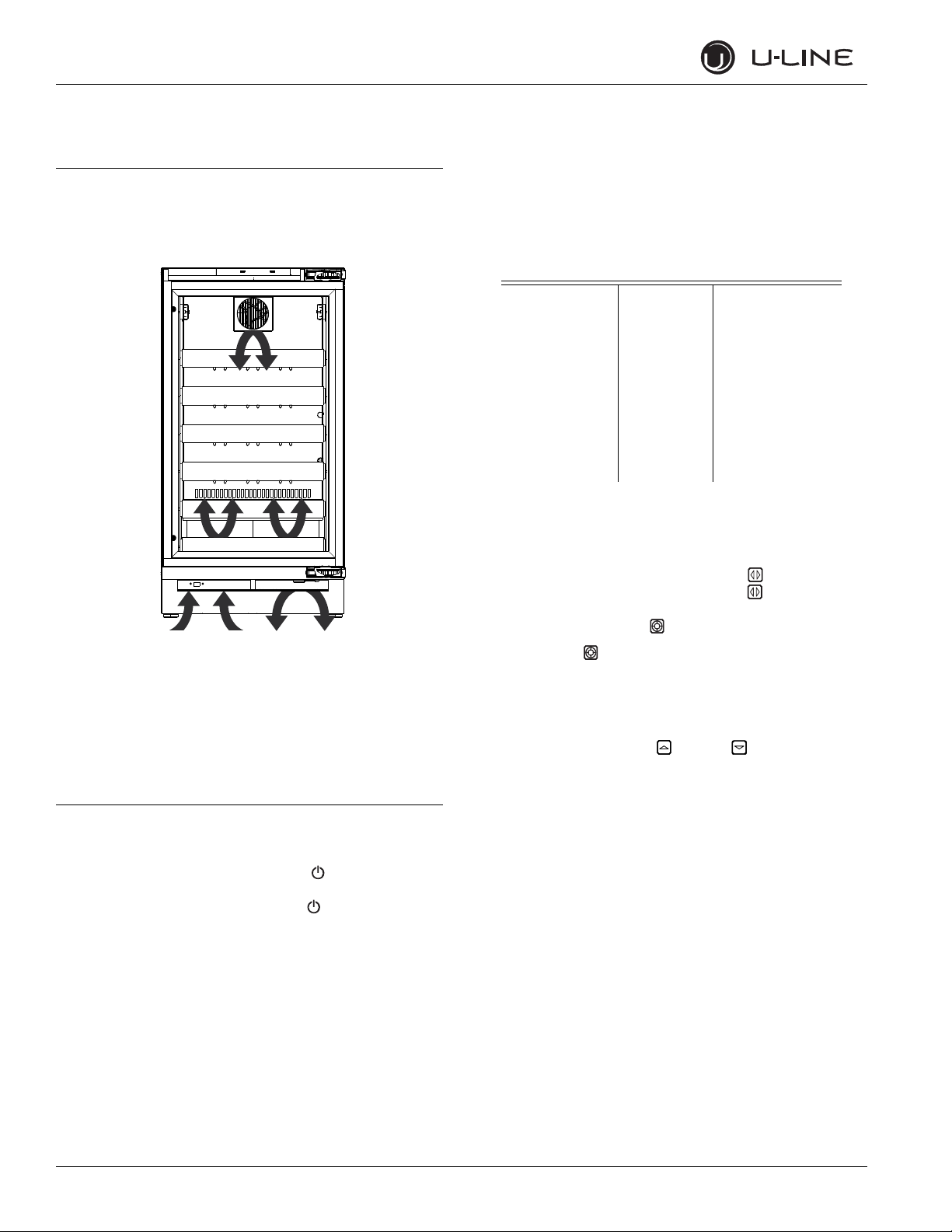
Door Removed For Illustration Purposes
Internal Air Flow And Unit Ventilation Diagram
Air Flow
The unit requires proper air flow to perform at its highest
efficiency. Do not block the front grille, internal fans or vents
at any time, or the unit will not perform as expected. Do not
install the unit behind a door.
Initial Startup
All U-Line controls are preset at the factory. Initial startup requires
no adjustments.
Adjusting Temperature Settings
Each zone has a Series of Zone Settings with a default value for each
setting. Each Zone Setting can be further customized by fine tuning
the temperature set point. See the table below for a description of
each Zone and Zone temperature ranges. Zone selection will vary by
model.
Zone Settings Chart
Setting Default (°F) Range (°F)
Red Wine 55° 55° - 65°
White Wine 50° 45° - 55°
Sparkling Wine 45° 38° - 50°
Beverage 38° 34° - 65°
Market 38° 34° - 40°
Root 50° 45° - 55°
Pantry 42° 34° - 70°
Deli 36° 34° - 40°
The 3036 Models have two independently controlled zones. Each
zone may have its own Zone and set point. The 3018 models have a
single zone. Available Zones Settings will vary with model.
1. In order to adjust temperatures in the 3036 you must first select a
Zone to adjust. To select, press Zone Toggle . The left side
Zone Setting will flash. Pressing Zone Toggle again will select
the right side and the right side Zone Setting will flash. For 3018
Models simply press Select to activate Zone Setting mode.
2. Pressing Select will cycle through each available zones.
Reference the Zone Settings Chart on
default set point and range.
3. Once you have selected your desired Zone Setting the default set
temperature will display. You may further fine tune the
temperature by pressing Up
pg 3
for each Setting’s
or Down .
U-Line recommends allowing the unit to run overnight
before loading refrigerator with product.
To turn the unit off, press and hold POWER for 5 seconds and
release. The display will show a countdown to switching the unit off.
To power the unit on simply press POWER
immediately switch on.
and the unit will
OLED Electronic Control Display
Digital Display.
The 3000 Series units are controlled by a feature rich, advanced
OLED display control unit. The control panel allows adjustment to
temperature set point, access to Energy Saver Mode, internal
temperature readings, and many other features.
7U-Line Service
Page 13

General Information
Up
Select
Down
U-Select Lighting
Power
Up
Select
Down
WELCOME TO THE
CUSTOMER MENU. USE
UP/DOWN ARROWS TO
SCROLL SETTINGS.
Up
Select
Down
3036 Model Display Shown
RETURN TO MENU
ACTUAL TEMPS
LEFT ZONE = 38°F
RIGHT ZONE = 38°F
WHITE WINE
5500 FF
OO
Up
Select
Down
Power
Energy Saver Mode
Indicator
Interior Lighting
U-Line 3000 Series unit uses a state of the art theatre style LED
lighting system.
Note: Lighting system is designed to fade in and out when switching
states.
1. To begin, press U-Select Lighting to enter the lighting menu.
2. Use Up or Down to cycle through each available brightness
setting; Low, Medium, or High.
3. Use U-Select Lighting to cycle through each available timer
setting. Selections include “On With Door”, “On 3 Hours”, “On 6
Hours”, or “On 24 Hours”.
4. To exit, press Select or simply wait for the menu to time out.
Customer Menu
Actual Temps
The Actual Temps option displays the actual temperature of each
zone, evaporator, as well as ambient temperature.
1 . To v ie w A ct u a l Te m p s f i r st s e le c t A c t u a l Te mp s f ro m t h e
customer menu.
2. Use Up or Down to scroll through available information.
3. To exit, Select
Return to Menu.
Energy Saver
The 3000 Series of U-Line undercounter refrigeration appliances
contain a feature rich customer menu. The Customer Menu allows
access to a series of advanced features including Energy Saver Mode,
Sabbath mode, Actual Temp readings as well as a method to restore
factory defaults.
1. To access the Customer Menu hold down both Up and Select
for 5 seconds.
2. Use Up or Down to scroll through available selections.
3. Use Select to enter selected sub-menu.
4. To exit Customer menu, Use Down to scroll to the bottom of
the display and use Select to Select “Exit.”
Energy Saver mode reduces overall energy consumption by altering
user set point, differential, lighting and tone settings. When in Energy
Saver mode a small leaf icon will be displayed on the main screen.
1. To enter Energy Saver first select Energy Saver from the
Customer Menu.
2. Use Down to select “Off” in the menu.
3. Press Select .
4. Use Up or Down to change the selection from Off to On.
5. Press Select to confirm your selection.
6. To exit Energy Saver mode simply return to the Customer Menu,
Select Energy Saver mode and change “On” to “Off”.
U-Line Service 8
Page 14

General Information
Up
Select
Down
RETURN TO MENU
SABBATH MODE
OFF
Up
Select
Down
RETURN TO MENU
LANGUAGES
ENGLISH
Up
Select
Down
RETURN TO MENU
SOUND LEVEL
HIGH
Up
Select
Down
RETURN TO MENU
FARENHEIT/CELSIUS
DEGREES = °F
Sabbath Mode
The U-line 3000 Series of models offer a Sabbath mode for users
who celebrate certain Sabbaths. Sabbath mode disables system
responses to user initiated activities and all external functions;
including lighting, display and audible alarms. The unit will still
maintain internal temperatures and set points.
1. To enter Sabbath Mode, select Sabbath Mode from the Customer
Menu.
2. Use Down to select “Off”.
3. Press Select , “Off ” will begin to flash.
4. Use Up or Down to change “Off ” to “On”.
5. Press Select to Confirm your selection.
The Display will fade out as the unit enters Sabbath Mode. Sabbath
remains active until the Power Button is pushed.
Sound Level
Audible alarms and alert tones support four different Sound Level
settings, High, Medium, Low, and Off.
To select a new sound level, enter the Sound Level menu from the
Customer Menu.
1. Use
Up or Down
to select the current sound level.
2. Press Select , the current setting will begin to flash.
3. Use Up or Down to select a different level.
4. Use Select to confirm your choice.
Fahrenheit / Celsius
Languages
The U-Line 3000 Series of models supports a number of Display
Languages including English, Spanish, French and German.
To Change Display Language select Languages from the Customer
Menu.
1. Use Down to select “English”.
2. Press Select , “English” will begin to flash.
3. Use Up or Down to cycle through the available Languages.
4. Press Select to confirm you choice.
Temperature and Set point information can be displayed in either
Fahrenheit or Celsius.
To change from Fahrenheit to Celsius enter the Fahrenheit / Celsius
menu from within the Customer Menu.
1. Use
Down
to select “Degrees”.
2. Press Select . The selection will begin to flash.
3. Use Up or Down to select between °F (Fahrenheit) or °C
(Celsius).
4. Press Select to confirm your choice.
9U-Line Service
Page 15

General Information
Up
Select
Down
RETURN TO MENU
Help
Model 3018WC
1-800-779-2547
Up
Select
Down
RETURN TO MENU
ACTUAL TEMPS
ZONE = 37°
EVAP = 52°
Up
Select
Down
RETURN TO MENU
ALL ERRORS
NO COMM 0
ZONE T OPEN 0
Help
To access the Help menu select Help from the Customer Menu. Use
the Up or Down to scroll through available information. The
Help screen displays the following.
•Model.
• U-Line Contact Phone Number.
•Software version.
• Serial Number.
To exit the Help menu use Up to select “Return to Menu” and
press Select to confirm.
Service Menu
In addition to a feature rich customer menu, the 3000 series also
offers a service menu with the ability to fine tune and monitor unit
operation.
To initiate the Service menu holed both Up and Zone Toggle
for a few seconds.
Actual Temps
The Actual Temp option in the service menu will display raw
thermistor readings without calculating offsets.
1. Use Down to select “Actual Temps”.
2. Press Select
3. Use Up and
readings.
To exit the Actual Temps menu use Up to select “Return to
Menu” and press Select to confirm.
Down to scroll through available thermistor
All Errors
The All Errors option keeps record of any system errors. When an
error occurs it is recorded to all errors. The number next to the
error idicates the number of recorded instances. Errors in the log
may not be currently active. The error log memory is non volatile and
is persistent should power be lost and restored to the unit. See
below for a list of logged errors and their respective descriptions.
ID Description Solution
Unit lost
No Comm
communication to the
display
Zone T
Open
Evap T Open
Amb Thrm
Open
Zone T
Short
Evap T Short
Amb Thrm
Short
Te m p H i
6H+
Te m p H i
12H+
Te m p L o
6H+
Te m p L o
12H+
Zone thermistor circuit
open.
Evaporator thermistor
circuit open.
Ambient thermistor
circuit open.
Zone thermistor circuit
shorted.
Evaporator thermistor
circuit shorted.
Ambient thermistor
circuit shorted
Zone temperature +10°
over set point for over 6
hours.
Zone temperature +10°
over set point for over
12 hours.
Zone temperature -10°
under set point for over
6 hours.
Zone temperature -10°
under set point for over
12 hours.
Door Open 5MDoor switch open for
more then 5 minutes.
To access All Errors follow the steps below.
Check display cable.
Replace if necessary.
Check connection. Replace
if necessary
Check connection. Replace
if necessary
Check connection. Replace
if necessary
Check connection. Replace
if necessary
Check connection. Replace
if necessary
Check connection. Replace
if necessary
Check compressor,
evaporator fan and related
relays and DC outputs.
Check compressor,
evaporator fan and related
relays and DC outputs.
Check compressor,
evaporator fan and related
relays and DC outputs.
Check compressor,
evaporator fan and related
relays and DC outputs.
Check reed switch and
connection.
1. Use Down to select “All Errors”.
2. Press Select
3. Use Up and
Down to scroll through available information.
U-Line Service 10
Page 16

General Information
Up
Select
Down
RETURN TO MENU
RELAY STATUS
MULL COND DEF LVLV
OFF OFF OFF OFF
Up
Select
Down
RETURN TO MENU
RELAY TOGGLE
MULL OFF
COND OFF
To clear the error log use Down to select “Clear Errors” and
press Select to confirm.
To exit the Actual Temps menu use Up to select “Return to
Menu” and press Select to confirm.
Relay Status
Relay status displays the current state of each relay. While all available
relays are displayed, only a portion are used.
ID Description Status
Mull Mullion Heater Not Used
Cond Condenser Fan Not Used
Def Defrost Valve Not Used
LV LV Left Vale Not Used
RVLV Right Valve Not Used
Pan Pan heater Not Used
Comp Compressor Used
Note: The Cond (Condenser Fan) will switch state with the
compressor relay, however the condenser fan is actually powered
through a DC switch and is independent of the Cond relay.
Condenser fan status can be viewed through the “Output” service
menu option.
To access Relay Status
1. Use Down to select “Relay Status”.
2. Press Select
3. Use Up and
To exit the Relay Status simply press Select to exit.
Down to scroll through available information.
Relay Toggle
Relay toggle is used to manually switch the state of each relay to test
for proper operation. In addition to the AC relays, DC switches may
also be toggled. Relay toggle can also be used to force the unit into a
particular state. For example, to force a 3018 / 3045 into a cooling
cycle activate Comp, F1, and F3.
ID Description Ty p e
Mull Mullion Heater (Not Used) AC
Cond Fan (Not Used) AC
Def Defrost Valve (Not Used) AC
LV LV Left Vale (3036 / 3090 Only) AC
RVLV Right Valve (3036 / 3090 Only) AC
Pan Pan heater (Not Used) AC
Comp Compressor AC
F1 Evaporator Fan DC
F2 Evaporator Fan (3036 / 3090 Only) DC
F3 Condenser Fan DC
L1 Cabinet Lighting DC
L2 Cabinet Lighting (3036 / 3090 Only) DC
To a cc e s s R e la y To g gl e
4. Use Down to select “Relay Toggle”.
5. Press Select
6. Use Up and
7. Press Select to toggle
To exit the Actual Temps menu use Up to select “Return to
Menu” and press Select to confirm.
Down to scroll through each option.
11 U-Line Service
Page 17

General Information
Up
Select
Down
RETURN TO MENU
INPUT STATUS
DOOR OPEN
IN2 OPEN
Up
Select
Down
RETURN TO MENU
OUTPUTS
EVAP FAN=0%
CONDENSER FAN=0%
Up
Select
Down
RETURN TO MENU
OFFSETS
ZONE = 1°F
EVAP = 1°F
Up
Select
Down
RETURN TO MENU
SELF TEST
NO ERRORS
try “RELAY TOGGLE”
Input Status
Input status displays the current state of each available input as well as
the current USB connection state.
ID Description States
Door Door Switch Open - Closed
IN2 Input 2 - Not Used Open
Test Input Factory Test Input Open
USB USB Connection State Flash - Com Port
Note: USB status show current connection state. In order to make a
successful connection USB connection type must be properly set in
“USB Port” under the service menu.
To access Input Status
1. Use Down to select “Input Status”.
2. Press Select
3. Use Up and
Down to scroll through available information.
To exit the Input Status menu use Up to select “Return to Menu”
and press Select to confirm.
Outputs
Offsets.
Offsets are used to adjust or correct thermistor readings. Offset
values are added to the current thermistor reading and are then used
by the control board to determine cooling and defrost cycle times.
Offsets have a range of +/- 10°F. Corrected values may be viewed
through the customer “All Temps” menu or TTY output.
To access Offsets
1. Use Down to select “Offsets”.
2. Press Select
3. Use Up and
Down to scroll through available thermistors.
To change offset
4. Press Select
5. use Up
6. Press Select
, the selected thermistor will begin to flash
or Down to modify offset value
to confirm setting
To exit the Offset menu use Up to select “Return to Menu” and
press Select to confirm.
Self Test
Outputs is used to monitor the state of DC outputs.
ID Description States
Evap Fan Evaporator Fan 0 - 100%
Condenser Fan Condenser Fan 0 - 100%
Light Interior Lighting Off - Low - Med - High
To access Outputs
1. Use Down to select “Outputs”.
2. Press Select
3. Use Up and
To exit the Input Status menu use Up to select “Return to Menu”
and press Select to confirm
Down to scroll through available information.
U-Line Service 12
Self test is used to initiate a self diagnostic report. Any system faults
will be displayed under Self test. If no errors are present “no errors”
will be displayed and the main control board is functioning properly. If
an error is listed attempt to correct it before changing control board.
See troubleshooting for tips on correcting errors.
To access Self Test
1. Use Down to select “Self Test”.
2. Press Select
3. Use Up and
Down to scroll through available information.
To exit the Self Test use Up to select “Return to Menu” and press
Select to confirm.
Page 18

General Information
Up
Select
Down
RETURN TO MENU
DIFFERENTIALS
ZONE = 1°F
45° Set Point
1° Differential
2° Differential
3° Differential
Up
Select
Down
RETURN TO MENU
SET POINTS
ZONE = 38°F
EVAP = 42°F
Up
Select
Down
RETURN TO MENU
FACTORY DEFAULT
RESTORE?
Differentials
Differentials are used to determine the maximum variation from set
point and have a range of 0 through 10. The table below shows the
effect of differentials on cooling cycles with a set point of 45°
Note: Air temperature does not reflect product temperatures. .
Differential Cycle Start Cycle End
0 46° 44°
1 47° 43°
2 48° 42°
3 49° 41°
4 50° 40°
5 51° 39°
The graph below shows a unit’s cooling cycle over time with various
differentials
Set Points
The Set points menu allows has options to modify both the Zone and
Evap set points. Changes to the zone set point will be reflected on
the main screen. Changes to the evap set point alter the temperature
the evaporator needs to meet during a defrost cycle.
To access Set Points
1. Use Down to select “Set Points”.
2. Press Select
3. Use Up and
To c ha n ge s e t po i nt
4. Press Select
5. use Up
6. Press Select
To exit the Set Points menu use Up to select “Return to Menu”
and press Select to confirm.
Down to scroll through available set points.
, the selected set point will begin to flash
or Down to modify the value
to confirm setting
Factory Default
Factory Default will restore all settings to their factory default.
To access Factory Default
1. Use Down to select “Factory Default”.
2. Press Select
To restore settings to their factory default.
3. Use
4. “Restore?” will change to “Restoring...” while settings are restored.
To exit Factory Default use Up to select “Return to Menu” and
press Select to confirm.
Down to select “Restore?” and press
Select
When restoration is complete, “Restoring...” will return to
“Restore”.
13 U-Line Service
Page 19

General Information
Up
Select
Down
RETURN TO MENU
RE-SELECT MODEL #
3018R
Up
Select
Down
RETURN TO MENU
FAN DELAY
FAN DELAY ON = 1
FAN DELAY OFF = 2
Up
Select
Down
RETURN TO MENU
USB PORT
PC Link
Re-Select Model
Re-Select Model allows the units model information to be modified.
Changing the units model completely reprograms available zones,
relay assignments, dc output assignments etc.
To access Re-Select Model
1. Use Down to select “Re-Select Model”.
2. Press Select
To alter model setting.
3. Use
Down to select “Model=” and
press Select . “Model”
will begin to flash.
4. Press Up
or Down to scroll through each available model.
5. Press Select to confirm.
To exit Re-Select Model use Up to select “Return to Menu” and
press Select to confirm.
Fan Delay
To alter fan settings.
3. Use
4. Press Up
Down to select either “Fan Delay On” or “Fan Delay
Off” and
press Select . The chosen option will begin to flash.
or Down to change settings.
5. Press Select to confirm.
To exit Fan Delay use Up to select “Return to Menu” and press
Select to confirm.
USB Port
The USB Port menu option allows the selection of a communication
mode. The 3000 Series can communicate either via TTY to a PC or
log diagnostic information directly to a USB flash disk.
ID Communication
PC Link PC TTY
Flash USB Flash Drive
To access USB Port
1. Use Down to select “USB Port”.
The Fan Delay menu option allows the modification of fan run times
during a cooling cycle. In order to allow time for the evaporator to
properly cool, the evaporator fan is delayed from starting with the
cooling cycle for a given amount of time. In order to remove as much
warmth as possible from the cabinet the evaporator will continue to
run at the end of the cooling cycle for a given amount of time.
Fan Delay On=
“Fan Delay On” is the amount of time in minutes the fan will be
delayed from starting from the beginning of a cooling cycle.
Fan Delay Off=
“Fan Delay Off” is the amount of time in minutes the fan will
continue to run at the end of a cooling cycle.
To access Fan Delay
1. Use Down to select “Fan Delay”.
2. Press Select
2. Press Select
To alter communication settings.
3. Use
4. Press Up
Down to select the current setting and press Select
or Down to change settings.
.
5. Press Select to confirm.
To exit “USB Port” use Up to select “Return to Menu” and press
Select to confirm.
U-Line Service 14
Page 20

General Information
Up
Select
Down
RETURN TO MENU
SHOWROOM MODE
OFF
Showroom Mode
Showroom displays a number of features and allows the unit to be
powered on without running the cooling system.
To toggle showroom mode
1. Use Down to select “Showroom Mode”.
2. Press Select
3. Use
Down to select “Off” and
begin to flash.
4. Press Up
or Down to toggle between off and on.
5. Press Select to confirm.
press Select . “Off” will
If set to “on” showroom mode will begin immediately. To exit
showroom mode press and release Power
To exit the showroom mode menu use Up to select “Return to
Menu” and press Select to confirm.
15 U-Line Service
Page 21

Electronic Control Quick Guide
OFF
RED WINE
55 F
OO
RED WINE
55 F
O
RED WINE
55 F
O
SET
U-SELECT LIGHTING
DOOR ONLY
LIGHTING
LEVEL
HIGH
Ta s k Press Display Comment
Power ON/OFF
General Information
Display will begin a 5 second
countdown To Power Off.
Select Zone
(3036 Models Only)
Select Zone
Ty p e
Fine Tune Temperature
Set Point
Adjust Cabinet Lighting
Display will show The selected zone.
Zone will flash during selection.
Continue to press Select button to
cycle through all available zones.
Set will appear while adjusting set
point.
Use Light button to scroll through
light settings. See Page 8 for more
detailed instructions.
U-Line Service 16
Page 22

General Information
USB Communication
The 3000 series uses an advanced USB logging feature for system
logging and diagnostics. The controller outputs 36 separate data
points per second to either a USB flash disk or transmits over USB
via TTY to a client PC. To prepare the unit for logging, first verify the
USB port is set to the proper configuration. See “USB Port” on page
14 for information on configuring the USB port.
Flash Mode:
Suitable for logging directly to a USB flash disk.
PC Link Mode:
Suitable for communicating directly with another PC via USB.
USB Communication (Flash)
The main control can host a wide range of flash disks up to a max
capacity of 8GB. After verifying the USB port is set to “Flash” simply
insert a flash disk in to the USB port located above the grille. The
flash disk activity light (located on the flash disk) will begin flashing
immediately as data is recorded to the drive. Data is recorded in one
second increments and is only limited by the capacity of the flash disk.
The system will create a file named “uline.csv” on the flash disk. In
the event the file already exists, new data will automatically be
appended to the end of the existing file. The file is output in a comma
delineated text format and may be viewed in a wide variety of simple
text readers or spreadsheet programs.
For information on identifying each data point, see the
“Communication Data” table on page 18.
USB Communication (PC Link)
Data can be transmitted directly to a client PC via a serial
connection. Verify the USB port is set to “PC Link”. Use a Type A to
Type A male to male USB cable to connect the system to a
Windows® compatible PC. It is necessary to install communication
drivers to the client PC. Drivers may be downloaded at
www.u-lineservice.com. Establish a connection using a Telnet / TTY
terminal application. U-Line recommends PuTTY. PuTTY is available
for download at www.u-lineservice.com. Once the connection is
established, the controller will output a series of 36 data points in 1
second increments. For information on identifying each data point,
see the “Communication Data” table on page
18.
17 U-Line Service
Page 23

General Information
Communication Data ID Table
Field 1 2 3 4 5 6 7 8 9 10
ID
Sample
Data
Field 11 12 13 14 15 16 17 18 19 20
ID
Sample
Data
Field 21 22 23 24 25 26 27 28 29 30
ID
Sample
Data
Time
Live
1525 36 --- 5 --- 85 111 Beverage 34 1
Zone
Offset
0 0 --- --- --- 2 --- --- --- ---
Relay 7
Indicator
7 1 --- 3 0 --- --- --- --- 45
Zone
Te m p
Evap
Offset
Evap Fan
Indicator
Not
Used
Door
Indicator
Not
Used
Evap
Te m p
Not
Used
Cond Fan
Indicator
Not
Used
Relay 1
Indicator
Light
Level
Ambient
Te m p
Relay 2
Indicator
Not
Used
Proc
Te m p
Relay 3
Indicator
Energy
Saver
Zone
ID
Relay 4
Indicator
Sabbath
Set
Point
Relay 5
Indicator
Power
Indicator
Differential
Relay 6
Indicator
Comp
Timer
Field 31 32 33 34 35 36
ID
Sample
Data
Comp
Cumulative
500 --- 0 0 0 0
Field Value Field Value
1 Time in seconds since unit plugged in. 19 Relay 5 (unassigned). “5” = active, “---” = inactive.
2 Temperature of Zone in °F/°C. 20 Relay 6 (unassigned). “6” = active, “---” = inactive.
3 Not used. 21 Compressor relay. “7” = active, “---” = inactive.
4 Evaporator temperature in °F/°C. 22 Evaporator fan. “1” = active, “---” = inactive.
5 Not used. 23 Not used.
6 Ambient temperature in base of unit °F/°C. 24 Condensor fan. “3” = active, “---” = inactive.
7 Board processor temperature. 25 LED intensity, provided in %.
8 Zone identification tag. 26 Not used.
9 Zone set point in °F/°C. 27 Energy Saver mode indicator. “E” = active.
10 Differential value in °F/°C. 28 Sabbath mode indicator. “S” = active.
11 Zone offset value in °F/°C. 29 Soft power indicator. “P” = unit in “On” mode.
12 Evaporator offset value in °F/C. 30 Compressor state change timer, in seconds.
13 Door status indicator. “L” = Open “---” = closed. 31 Compressor cumulative run time, in seconds.
14 Not used. 32 Max remaining defrost time, in seconds.
15 Relay 1 (unassigned). “1” = active, “---” = inactive. 33 Evaporator fan state change timer, in seconds.
16 Relay 2 (unassigned). “2” = active, “---” = inactive. 34 Not used.
17 Relay 3 (unassigned). “3” = “active”, “---” = inactive. 35 Cumulative time spent in limp mode, in seconds.
18 Relay 4 (unassigned). “4” = “active”, “---” = inactive. 36 Not used.
Defrost
Timer
Fan 1
Timer
Not
Used
Limp
Timer
Not
Used
Note: Relay 2 will cycle with relay 7, this is considered normal.
U-Line Service 18
Page 24

General Information
IMPORTANT
IMPORTANT
Upper
Back Panel
Fan
Electrical
Connection
Evaporator Plate
Screws
Convection Cooling
All 3000 series units are equipped with an advanced convection
cooling system. Convection cooling stabilizes cabinet temperature,
cools product faster and increases energy efficiency.
Evaporator Fan
The evaporator fan is responsible for circulating warm are from the
refrigeration zone, pass the evaporator and back into the refrigerated
zone,
The evaporator fan is factory set to have a 1 minute delay at the
beginning of a cooling cycle. This delay gives the evaporator time to
cool properly before warm air is passed over it. The fan will continue
to run for an additional 2 minutes at the end of a cooling cycle. Fan
delay times can be modified through the service menu. See “Fan
Delay” on page
Evaporator fan operation is also determined by door switch state. If
the door switch circuit opens the fan will stop. When the door
switch circuit is closed the fan will either continue running with the
cooling cycle, or if not currently cooling the fan will run for 1 minute
to circulate air and clear any condensation that may have appeared on
glass doors and shelves.
Note: If the unit is set to sabbath mode the evaporator fan will no
longer respond to the state of the door switch.
In order to operate efficiently the evaporator fan blade and vents
should be unobstructed and free of any dust build up.
Evaporator Fan Replacement
14.
5. Remove insulating foam from refrigerant line pass-through hole.
6. Remove internal shelving, bins, or wine racks.
7. Remove shelf clips, rack, or bin mounting rails.
8. Remove thermistor cover.
9. Remove two evaporator plate screws from top of evaporator
plate.
10. Grasp evaporator fan shroud and gently pull plate away from the
rear of the unit.
11. While pulling the evaporator plate clear of the unit, it may be
necessary to use your free hand to manipulate the fan plug end
through the pass-through hole.
12. Remove the 4 screws mounting the fan shroud to the evaporator
plate.
Should the evaporator fan need to be replaced follow the steps
below.
1. Remove any product from the unit.
2. Disconnect power to the unit.
3. Remove upper back panel.
4. Disconnect fan electrical connection
13. Remove and replace fan. Take special care to properly route fan
wire.
Fan must be oriented to pull air in through lower evaporator
plate vents and push air out at fan mounting location.
14. Installation is the reverse of removal. Before replacing back panel
fill refrigerant line pass-through hole with sealant gum.
19 U-Line Service
Page 25

General Information
IMPORTANT
IMPORTANT
WARN ING
Wrap Screws
Cable Arm
Step 1
Step 2
Door Top
Door Bottom
Press Tab Down
T-25 Torx Screw
T-25 Torx Screw
Door Alignment and Adjustment
Align and adjust the door if it is not level, or is not sealing properly. If
the door is not sealed the unit may not cool properly, or excessive
frost may form in the interior.
Properly aligned, the door’s gasket should be firmly in
contact with the cabinet all the way around the door (no
gaps). Carefully examine the door’s gasket to assure that it is
firmly in contact with the cabinet. Also make sure the door
gasket is not pinched on the hinge side of the door.
• Do not attempt to use the door to raise or pivot the
unit. This would put excessive stress on the hinge system.
• Pay special attention to the Cable Arm. Make sure not to
over extend or damage it during door alignment
Stainless Models (Removing Wrap)
15. Open door completely
16. Use a short phillips head screw driver to remove wrap screws
from bottom of the door.
17. Remove the two wrap screws from the bottom of the stainless
steel door wrap.
19. The Wrap hinges on top of the door. Carefully pull wrap away and
then up
. See Below.
20. Remove cable from display by pressing the release pin on the cable
connector.
18. Gently pull bottom of wrap away from door.
Alignment and Adjustment
1. Using a T-25 Torx Bit,
loosen each pair of torx
head screws on both the
upper and lower hinge
plate.
2. Square and align door as
necessary
3. Tighten Torx head screws
on hinge
4. If necessary re-install
Stainless steel wrap.
U-Line Service 20
Page 26

Troubleshooting
Troubleshooting
Customer Call Guide
The following guide has been developed to help answer frequently asked questions. It can be used by persons scheduling service calls. These are
things the customer should consider before scheduling a service call.
Concern Response
The unit is not cold enough. • Are you familiar with the factory temperature specifications for
the unit? Many factors can cause these temperatures to vary;
ambient temperature, application, amount of use (number of
times and length of time the door or drawers are opened and
closed), etc
• Is the door or drawers sealing properly? If the door or drawer is
not sealed properly, it allows heat into the unit. U-Line’s war
ranty is 30 days for door or drawer adjustments.
• Has the door or drawers been left open? The unit will issues an
audible tone if the door/drawer has been left open for longer
than 5 minutes.
• Is the condenser clean? U-Line’s warranty does not cover clean-
ing the condenser.
• Is the unit behind closed doors or the grille restricted? The front
grille must be free of obstruction.
• Is the unit in an application of heavy usage? Heavy usage or high
ambient temperatures will cause a unit to frost up.
• Did you try adjusting the temperature to a colder level? Adjust
to a colder level. Be sure to allow 24 hours between temperature
control adjustments.
Temperature is too cold. • Check actual temperature versus set-point.
• Did you try adjusting the temperature to a warmer level? Adjust
to a warmer level and allow 24 hours between temperature con
trol adjustments.
Product is freezing. • What is the temperature set at?
• Do not allow products to lean against the evaporator at the back
wall.
The unit is frosting up. • Are you familiar with the defrost technology of the unit?
• Is the door or drawers sealing properly? If the door or drawer is
not sealing properly, it allows heat/humidity into the unit. U-
Line’s warranty is 30 days for door/drawer adjustments.
• Has the door/drawers been left open?
• Is the unit in an application of heavy usage? Heavy usage or high
ambient temperatures will cause a unit to frost up.
-
-
21 U-Line Service
Page 27

Troubleshooting
CAUTION
Never attempt to repair or perform maintenance on the unit until the main electrical power has been disconnected from the
unit.
Cause Remedy
Compressor overheating
1. Condenser air flow restricted.
2. Condenser fan blade obstructed.
3. Condenser fan motor stalled.
4. Compressor inoperable.
Compressor will not stop operating.
1. Temperature set too cold.
2. Control inoperable.
3. Control sensing bulb not sensing temperature.
4. Evaporator fan stalled.
Excessive frost buildup.
1. Door gasket not sealing properly.
2. Door out of alignment
3. Light stays on when door is closed.
4. Warm air leaking into cabinet from back.
Noisy.
1. Copper refrigeration tube touching cabinet.
2. Evaporator fan blade touching cover.
3. Condenser fan obstruction (wiring, foam insulation,
packaging material).
Ice Buildup in drain trough or drain problem
1. Obstructed drain cup or tube.
2. Kinked drain tube.
3. Drain trough spout and drain cup not aligned
1. Remove restriction (clean condenser and grille).
2. Remove blade restriction
3. Replace fan motor
4. Replace compressor
1. Adjust temperature warmer.
2. Replace control.
3. Check bulb/thermistor for location and ohms.
4. Remove obstruction or replace motor.
1. Adjust door or replace door gasket.
2. Adjust door hinges/pivot plates.
3. Repair or adjust light bracket/magnet.
4. Seal holes in the foam to prevent warm air entering the unit.
1. Carefully adjust tubing.
2. Adjust fan mounting or shroud.
3. Remove obstruction.
1. Check and clear drain tube.
2. Reroute drain tube.
3. Align drain trough and drain cup.
U-Line Service 22
Page 28

Troubleshooting
CAPILLARY TUBE
DRYER
CONDENSER
COMPRESSOR
EVAPORATOR
Compressor Information
Cooling process
Refrigerant is pumped from the compressor to the condenser as a
high pressure, high temperature vapor.
As the refrigerant cools in the high pressure condenser, the vapor
condenses to liquid. During this phase change, a great amount of heat
is rejected with the help of the condenser fan.
The liquid then flows to the dryer where it is strained and filtered.
From the dryer, the refrigerant flows through the capillary tube which
meters the liquid refrigerant to the evaporator.
The pressure of the refrigerant is reduced to the evaporating or low
side pressure.
The reduction of pressure on the liquid refrigerant causes it to boil
or vaporize until it reaches saturation temperature. As the low
temperature refrigerant passes through the evaporator coil, it
continues to absorb a lot of heat, causing the boiling action to
continue until the refrigerant is completely vaporized. It is during this
phase that the most heat is absorbed (the cooling takes place) in the
refrigerator.
The refrigerant vapor leaving the evaporator travels through the
suction line to the compressor inlet. The compressor takes the low
pressure vapor and compresses it, increasing both pressure and
temperature. The hot high pressure gas is pumped out the discharge
line and into the condenser. The cycle continues
23 U-Line Service
Page 29

Troubleshooting
DANGER
Magnet Close To Switch
(Door Closed)
(Switch Closed)
Magnet Away From Switch
(Door Open)
(Switch Open)
C
S
R
OVERLOAD PROTECTOR
STARTING RELAY
CAPACITOR
RELAY COVER
Thermistors
Thermistors are used for various temperature readings. Thermistor
provide reliable temperature readings using a resistance which varies
based on surrounding temperatures. If a faulty thermistor is
suspected it may be tested using an accurate ohmmeter. In an ice bath
(32°F) resistance should measure 16.1 kilohms,
5K Ohms - 70°F ambient.
16.1K Ohms - 32°F ambient
Thermistor Failure
Zone Thermistor
If the zone thermistor fails the unit will continue to operate on a
preset time interval of 10 minutes on and 30 minutes off. The unit
will otherwise operate normally. The error will be displayed on
the main display and “Self Test” and logged in “All Errors”.
Evaporator Thermistor
If the evaporator thermistor fails the unit will rely on a preset
defrost timer during defrost cycles. The unit will otherwise
operate normally. Evaporator thermistor errors are hidden from
the display and recorded in “All Errors” and displayed in “Self
Te s t ” m o d e s .
Ambient Thermistor
The ambient thermistor is mainly used for diagnostics. If the
thermistor fails the unit will operate normally.
Reed Switch
A reed switch is used to monitor door state. The switch side is
mounted under the cabinet and the magnet is mounted to the cable
arm. When the door is closed magnetic force pulls the reed to its
contact and closes the circuit which turns the light and display off.
When the door is open the reed pulls away from the contact and
opens the circuit. If the door or drawers are left open for longer than
5 minutes, the switch will trigger an error code and set an audible
.
warning
Compressors
Electrocution can cause death or serious injury. Burns from hot
or cold surfaces can cause serious injury. Take precautions when
servicing this unit.
• Disconnect the power source.
• Do not stand in standing water when working around
electrical appliances.
• Make sure the surfaces you touch are not hot or frozen.
• Do not touch a bare circuit board unless you are wearing
an anti-static wrist strap that is grounded to an electrical
ground or grounded water pipe.
• Handle circuit boards carefully and avoid touching
components
To measure the start winding resistance, measure across the C and S
pins.
To measure the run winding resistance, measure across the C and R
pins.
Also check S to R and you should get the sum of the run and start
windings.
To ensure the windings are not shorted, check the S and R to ground.
70077 70084
EMU30HSC EMU30HER
Voltage 115 220-240
Frequency 60 50-60
LRA 5.5 8.2
FLA 1.0 .76
Start Winding 7.0 39.1
Run Winding 8.4 24.6
Overload 71009 71031
Relay 71010 71030
Capacitor 71013 N/A
U-Line Service 24
Page 30

Troubleshooting
Refrigeration System Diagnosis Guide
System
Condition
Normal Normal
Overcharge
Undercharge
Partial
Restriction
Complete
Restriction
No Gas
Suction
Pressure
Higher than
Lower than
Somewhat lower
than normal -
in vacuum
normal
normal
In deep
vacuum
0 PSIG
to 25"
Suction
Line
Slightly below
room
temperature
Very co l d -
may frost heavily
Warm -
near room
temperature
Warm -
near room
temperature
Room
temperature
(cool)
Room
temperature
(cool)
Compressor
Discharge
Very hot Very hot Warm Cold Normal
Slightly warm to
hot
Hot Warm Warm
Very ho t
Room
temperature
(cool)
Cool to hot
Condenser Capillary
Hot to warm Cool Cold
Top passes warm
lower passes cool
(near room
temperature due
to liquid
Room
temperature
(cool)
Room
temperature
(cool)
Tube
Room
temperature
(cool) or colder
Room
temperature
(cool)
Room
temperature
(cool)
Evaporator Wattage
Extremely cold
near inlet - outlet
below room
temperature
Extremely cold
near inlet -outlet
below room
temperature
backing up
No refrigeration
No refrigeration
Higher than
normal
Lower than
normal
Lower than
normal
Lower than
normal
Lower than
normal
25 U-Line Service
Page 31

Fault System Diagnosis Guide
Error Solution 1 Solution 2 Solution 3
Inspect the UI data cable for
No Comm
Zone T Open
Evap T Open
Amb Thrm Open
Zone T Short
Evap T Short
Amb Thrm Short
Te m p Hi 6 H +
Temp Hi 12H+
Te m p Lo 6 H +
Te m p L o 12 H +
Door Open 5M Verify door closes properly.
continuity. Replace if necessary.
he main control board and UI.
Inspect zone thermistor connection.
Replace if necessary.
Inspect evaporator thermistor
connection. Replace if necessary.
Inspect ambient thermistor
connection. Replace if necessary
Inspect thermistor cable for pinch
points or damage. Replace if
Inspect thermistor cable for pinch
points or damage. Replace if
Inspect thermistor cable for pinch
points or damage. Replace is
If excessive frost is also noted,
inspect door and door gasket for
proper seal and alignment.
If excessive frost is also noted,
inspect door and door gasket for
proper seal and alignment.
Inspect main control for proper relay
Inspect main control for proper relay
necessary.
necessary
necessary.
operation.
operation.
Inspect main control wire harness for
splits or breaks. Repair split or cut
cabling.
Inspect main control wire harness for
splits or breaks. Repair split or cut
cabling.
Inspect main control wire harness for
splits or breaks. Repair split or cut
cabling.
Inspect wire harness from main
control board for pinch points or
damage. Repair split or pinched
cabling
Inspect wire harness from main
control board for pinch points or
damage. Repair split or pinched
cabling
Inspect wire harness from main
control board for pinch points or
damage. Repair split or pinched
cabling
Inspect evaporator fan for proper
operation.
Inspect evaporator fan for proper
operation.
Inspect refrigeration system.
Reference the Refrigeration System
Diagnosis Guide on page 25.
Inspect refrigeration system.
Reference the Refrigeration System
Diagnosis Guide on page 25.
Inspect cable arm, verify presence of
magnet, verify proper operation and
movement or arm.
Troubleshooting
Inspect refrigeration system.
Reference the Refrigeration System
Diagnosis Guide on page 25.
Inspect refrigeration system.
Reference the Refrigeration System
Diagnosis Guide on page 25.
Inspect reed switch wiring.
U-Line Service 26
Page 32

Parts Information
Power
Cord
Door
Handle
Door
Assembly
LED
Display
LED
Lens
Hinge
Assembly
Grile
Control
Thermistor
Front View Rear View
Compressor
Capacitor
Condenser
Fan
Dryer
Compressor
Relay
Compressor
Overload
Condenser
Thermistor
Bin
Bin
Lower
Thermistor
Evaporator
Fan
Evaporator
Plate
Door
Gasket
Evaporator
Evap Fan
Cover
Reed Switch
Cable Arm
Parts View & Listing
3018RF
Models Covered
U-3018RFOL-00 U-3045RFOL-00
U-3018RFOL-01 U-3045RFOL-01
3018RFS-00 U-3045RFS-00
U-3018RFS-01 U-3045RFS-01
27 U-Line Parts
Page 33

Parts Information
Part Number Cross Reference
U-3018RFOL-00 U-3018RFOL-01 U-3018RFS-00 U-3018RFS-01 U-3045RFOL-00 U-3045RFOL-01 U-3045RFS-00
Bin 26112 26112 26112 26112 26112 26112
Bin Lower 26113 26113 26113 26113 26113 26113
Cable Arm 80-25068-00 80-25068-00 80-25068-00 80-25068-00 80-25068-00 80-25068-00
Capacitor 71008 71008 71008 71008 n/a n/a
Compressor 70077 70077 70077 70077 70084 70084
Compressor Overload 71009 71009 71009 71009 71031 71031
Compressor Relay 71010 71010 71010 71010 71030 71030
Condenser 74010 74010 74010 74010 74010 71010
Condenser Fan 80-22008-00 80-22008-00 80-22008-00 80-22008-00 80-22008-00 80-22008-00
Control 68095 68095 68095 68095 68095 68095
Display 68099 68099 68099 68099 68099 68099
Door Assembly 80-17107-01 80-17107-12 80-17107-03 80-17107-14 80-17107-01 80-17107-12
Door Gasket 31493-18-BLK 31493-18-BLK 31493-18-BLK 31493-18-BLK 31493-18-BLK 31493-18-BLK
Door Handle N/A N/A 23050-01 23050-01 N/A N/A
Dryer 2694 2694 2694 2694 2694 2694
Evaporator 74006 74006 74006 74006 74006 74006
Evaporator Fan 67005 67005 67005 67005 67005 67005
Evaporator Fan Cover 26117-01 26117-01 26117-01 26117-01 26117-01 26117-01
Evaporator Plate 14261-01 14261-01 14261-01 14261-01 14261-01 14261-01
Grille 80-29098-08 80-29098-08 80-29098-08 80-29098-08 80-29098-08 80-29098-08
Hinge Assembly 80-16095-01 80-16095-01 80-16095-01 80-16095-01 80-16095-01 80-16095-01
LED 68100 68100 68100 68100 68100 68100
LED Lens 26116 26116 26116 26116 26116 26116
Power Cord 2992 2992 2992 2992 2993 2993
Reed Swtich Assembly 80-51016-00 80-51016-00 80-51016-00 80-51016-00 80-51016-00 80-51016-00
Thermistor 68092 68092 68092 68092 68092 68092
26112
26113
80-25068-00
n/a
70084
71031
71030
71010
80-22008-00
68095
68099
80-17107-03
31493-18-BLK
23050-01
2694
74006
67005
26117-01
14261-01
80-29098-08
80-16095-01
68100
26116
2993
80-51016-00
68092
U-3045RFS-01
Bin 26112
Bin Lower 23113
Cable Arm 80-25068-00
Capacitor n/a
Compressor 70084
Compressor Overload 71031
Compressor Relay 71030
Condenser 74010
Condenser Fan 80-2208-00
Control 68095
Display 68099
Door Assembly 80-17107-14
Door Gasket 31493-18-BLK
Door Handle 23050-01
Dryer 2694
Evaporator 74006
Evaporator Fan 67005
Evaporator Fan Cover 26117-01
Evaporator Plate 14261-01
Grille 80-29098-08
Hinge Assembly 80-16095-01
LED 68100
LED Lens 62116
Power Cord 2993
Reed Switch Assembly 80-51016-00
Thermistor 68092
U-Line Parts 28
Page 34

Parts Information
Power
Cord
Door
Handle
Door
Assembly
LED
Display
LED
Lens
Hinge
Assembly
Grile
Control
Thermistor
Front View Rear View
Compressor
Capacitor
Condenser
Fan
Dryer
Compressor
Relay
Compressor
Overload
Condenser
Thermistor
Crisper
Shelf
Assembly
Thermistor
Evaporator
Fan
Evaporator
Plate
Evaporator
Evap Fan
Cover
Door
Gasket
Reed Switch
Cable Arm
3018RGL
Models Covered
U-3018RGLOL-00 U-3045RGLOL-00
U-3018RGLOL-01 U-3045RGLOL-01
U-3018RGLS-00 U-3045RGLS-00
U-3018RGLS-001 U-3045RGLS-01
29 U-Line Parts
Page 35

Parts Information
Part Number Cross Reference
U-3018RGLOL-00 U-3018RGLOL-01 U-3018RGLS-00 U-3018RGLS-01 U-3045RGLOL-00 U-3045RGLOL-01 U-3045RGLS-00
Cable Arm 80-25068-00 80-25068-00 80-25068-00 80-25068-00 80-25068-00 80-25068-00 80-25068-00
Capacitor 71008 71008 71008 71008 n/a n/a n/a
Compressor 70077 70077 70077 70077 70084 70084 70084
Compressor Overload 71009 71009 71009 71009 71031 71031 71031
Compressor Relay 71010 71010 71010 71010 71030 71030 71030
Condenser 74010 74010 74010 74010 74010 71010 71010
Condenser Fan 80-22008-00 80-22008-00 80-22008-00 80-22008-00 80-22008-00 80-22008-00 80-22008-00
Control 68095 68095 68095 68095 68095 68095 68095
Crisper 26114 26114 26114 26114 26114 26114 26114
Display 68099 68099 68099 68099 68099 68099 68099
Door Assembly 80-17108-01 80-17108-12 80-17109-03 80-17109-14 80-17108-01 80-17108-12 80-17109-03
Door Gasket 31493-18-BLK 31493-18-BLK 31493-18-BLK 31493-18-BLK 31493-18-BLK 31493-18-BLK 31493-18-BLK
Door Handle N/A N/A 23050-01 23050-01 N/A N/A 23050-01
Dryer 2694 2694 2694 2694 2694 2694 2694
Evaporator 74006 74006 74006 74006 74006 74006 74006
Evaporator Fan 67005 67005 67005 67005 67005 67005 67005
Evaporator Fan Cover 26117-01 26117-01 26117-01 26117-01 26117-01 26117-01 26117-01
Evaporator Plate 14261-01 14261-01 14261-01 14261-01 14261-01 14261-01 14261-01
Grille 80-29098-08 80-29098-08 80-29098-08 80-29098-08 80-29098-08 80-29098-08 80-29098-08
Hinge Assembly 80-16095-01 80-16095-01 80-16095-01 80-16095-01 80-16095-01 80-16095-01 80-16095-01
LED 68100 68100 68100 68100 68100 68100 68100
LED Lens 26116 26116 26116 26116 26116 26116 26116
Power Cord 2992 2992 2992 2992 2993 2993 2993
Reed Switch Assembly 80-51016-00 80-51016-00 80-51016-00 80-51016-00 80-51016-00 80-51016-00 80-51016-00
Shelf Assembly 80-51017-00 80-51017-00 80-51017-00 80-51017-00 80-51017-00 80-51017-00 80-51017-00
Thermistor 68092 68092 68092 68092 68092 68092 68092
U-3045RGLS-01
Cable Arm 80-25068-00
Capacitor n/a
Compressor 70084
Compressor Overload 71031
Compressor Relay 71030
Condenser 74010
Condenser Fan 80-2208-00
Control 68095
Crisper 26114
Display 68099
Door Assembly 80-17109-14
Door Gasket 31493-18-BLK
Door Handle 23050-01
Dryer 2694
Evaporator 74006
Evaporator Fan 67005
Evaporator Fan Cover 26117-01
Evaporator Plate 14261-01
Grille 80-29098-08
Hinge Assembly 80-16095-01
LED 68100
LED Lens 62116
Power Cord 2993
Reed Switch Assembly 80-51016-00
Shelf Assembly 80-51017-00
Thermistor 68092
U-Line Parts 30
Page 36

Parts Information
Power
Cord
Door
Handle
Door
Assembly
LED
Display
LED
Lens
Hinge
Assembly
Grile
Control
Thermistor
Front View Rear View
Compressor
Capacitor
Condenser
Fan
Dryer
Compressor
Relay
Compressor
Overload
Condenser
Thermistor
Rack
Assembly 1
Rack Wood Trim
Rack
Assembly 3
Thermistor
Evaporator
Fan
Evaporator
Plate
Evaporator
Evap Fan
Cover
Door
Gasket
Rack
Assembly 2
Rack
Assembly 4
Reed Switch
Cable Arm
3018WC
Models Covered
U-3018WCOL-00 U-3045WCOL-00
U-3018WCOL-01 U-3045WCOL-01
U-3018WCS-00 U-3045WCS-00
U-3018WCS-01 U-3045WCS-01
31 U-Line Parts
Page 37

Parts Information
Part Number Cross Reference
U-3018WCOL-00 U-3018WCOL-01 U-3018WCS-00 U-3018WCS-01 U-3045WCOL-00 U-3045WCOL-01 U-3045WCS-00
Cable Arm 80-25068-00 80-25068-00 80-25068-00 80-25068-00 80-25068-00 80-25068-00 80-25068-00
Capacitor 71008 71008 71008 71008 n/a n/a n/a
Compressor 70077 70077 70077 70077 70084 70084 70084
Compressor Overload 71009 71009 71009 71009 71031 71031 71031
Compressor Relay 71010 71010 71010 71010 71030 71030 71030
Condenser 74010 74010 74010 74010 74010 71010 71010
Condenser Fan 80-22008-00 80-22008-00 80-22008-00 80-22008-00 80-22008-00 80-22008-00 80-22008-00
Control 68095 68095 68095 68095 68095 68095 68095
Display 68099 68099 68099 68099 68099 68099 68099
Door Assembly 80-17108-01 80-17108-12 80-17109-03 80-17109-14 80-17108-01 80-17108-12 80-17109-03
Door Gasket 31493-18-BLK 31493-18-BLK 31493-18-BLK 31493-18-BLK 31493-18-BLK 31493-18-BLK 31493-18-BLK
Door Handle N/A N/A 23050-01 23050-01 N/A N/A 23050-01
Dryer 2694 2694 2694 2694 2694 2694 2694
Evaporator 74006 74006 74006 74006 74006 74006 74006
Evaporator Fan 67005 67005 67005 67005 67005 67005 67005
Evaporator Fan Cover 26117-01 26117-01 26117-01 26117-01 26117-01 26117-01 26117-01
Evaporator Plate 14261-01 14261-01 14261-01 14261-01 14261-01 14261-01 14261-01
Grille 80-29098-08 80-29098-08 80-29098-08 80-29098-08 80-29098-08 80-29098-08 80-29098-08
Hinge Assembly 80-16095-01 80-16095-01 80-16095-01 80-16095-01 80-16095-01 80-16095-01 80-16095-01
LED 68100 68100 68100 68100 68100 68100 68100
LED Lens 26116 26116 26116 26116 26116 26116 26116
Power Cord 2992 2992 2992 2992 2993 2993 2993
Rack Assembly 1 18080-01 18080-01 18080-01 18080-01 18080-01 18080-01 18080-01
Rack Assembly 2 18074-01 18074-01 18074-01 18074-01 18074-01 18074-01 18074-01
Rack Assembly 3 18074-03 18074-03 18074-03 18074-03 18074-03 18074-03 18074-03
Rack Assembly 4 18074-02 18074-02 18074-02 18074-02 18074-02 18074-02 18074-02
Rack Wood Trim 39014-01 39014-01 39014-01 3904-01 3904-01 3904-01 3904-01
Reed Switch Assembly 80-51016-00 80-51016-00 80-51016-00 80-51016-00 80-51016-00 80-51016-00 80-51016-00
Thermistor 68092 68092 68092 68092 68092 68092 68092
U-3045WCS-01
Cable Arm 80-25068-00
Capacitor n/a
Compressor 70084
Compressor Overload 71031
Compressor Relay 71030
Condenser 74010
Condenser Fan 80-2208-00
Control 68095
Display 68099
Door Assembly 80-17109-14
Door Gasket 31493-18-BLK
Door Handle 23050-01
Dryer 2694
Evaporator 74006
Evaporator Fan 67005
Evaporator Fan Cover 26117-01
Evaporator Plate 14261-01
Grille 80-29098-08
Hinge Assembly 80-16095-01
LED 68100
LED Lens 62116
Power Cord 2993
Rack Assembly 1 18080-01
Rack Assembly 2 18074-01
Rack ASsembly 3 18074-03
Rack ASsembly 4 18074-02
Rack Wood Trim 3904-01
Reed Switch Assembly 80-51016-00
Thermistor 68092
U-Line Parts 32
Page 38

Wiring Diagram
POWER CORD
ASSEMBLY
GREEN (GROUND)
BLACK (HOT)
WHITE
(NEUTRAL)
BLUE (HOT)
TO COMPRESSOR
1
10
CONTROL
BOARD
NEUTRAL
DANFOSS
COMPRESSOR
CAPACITOR
RELAY
OVERLOAD
1
23
HOT
GREEN
(GROUND)
NEUTRAL
WHITE
HOT
BLUE
RELAY
EMBRACO
COMPRESSOR
GREEN
(GROUND)
ZONE TEMP
FUSE
TO
DISPLAY
ON DOOR
120
VOLT
PLUG
220 VOLT
PLUG
OVERLOAD
16
8
9
1
WHITE (NEUTRAL)
TO COMPRESSOR
6
1
10
5
TO
USB
ZONE EVAP
DOOR SWITCH
AMBIENT TEMP
TEST TERMINAL
EVAP FAN
LIGHT
CONDENSER FAN
FAN & LIGHT
HARNESS
THERMISTER
& SWITCH
HARNESS
GREEN (GROUND)
Models Covered
U-3018RFOL-00 U-3045RFOL-00
U-3018RFOL-01 U-3045RFOL-01
U-3018RFS-00 U-3045RFS-00
U-3018RFS-01 U-3045RFS-01
U-3018RGLOL-00 U-3045RGLOL-00
U-3018RGLOL-01 U-3045RGLOL-01
U-3018RGLS-00 U-3045RGLS-00
U-3018RGLS-01 U-3045RGLS-01
U-3018WCOL-00 U-3045WCOL-00
U-3018WCOL-01 U-3045WCOL-01
U-3018WCS-00 U-3045WCS-00
U-3018WCS-01 U-3045WCS-01
Wiring Diagrams
All Models
33 U-Line Service
Page 39

THIS PAGE INTENTIONALLY LEFT BLANK
U-Line Service
Page 40

The Built-In Undercounter Leader Since 1962
©2011 U-Line Corporation
Publication No. 30335 8/2011 Rev. A
ABOUT U-LINE
GENERAL INQUIRIES:
U-Line Corporation
P.O. Box 245040
Milwaukee, Wisconsin 53224-9540 U.S.A.
Phone (414) 354-0300
FAX (414) 354-7905
Email: sales@u-line.com
www.u-line.com
SERVICE ASSISTANCE:
Phone (800) 779-2547
FAX (414) 354-5696
Email: onlineservice@u-line.com
www.u-lineservice.com
PARTS ASSISTANCE:
E-mail: onlineparts@u-line.com
PRODUCT INFORMATION
Installation Guides with complete installation information, Custom Wood Panel Size Specifications & Installation Instructions, CAD Drawings, Use and Care Guides, Specifications & Feature Benefits are available for viewing and download on-line at www.u-line.com/customer-service/specs/.
Entertain with U-Line Elegance
BUILDING ON THREE GENERATIONS OF INNOVATION
For nearly five decades and three generations, U-Line continues to be the leader in innovation, quality and value in the
premium built-in undercounter ice making, refrigeration and wine preservation market. U-Line has captivated those
with an appreciation for the finer things with exceptional functionality, style, inspired innovation and attention to even
the smallest details. We are known and respected for our unwavering dedication to product design, quality and selection.
In 1962, Henry Uihlein founded U-Line Corporation as an outgrowth of Ben-Hur Freezer Company and was the first
to develop and patent an automatic stand-alone undercounter residential ice maker. His foresight and determination
to develop new ideas and to succeed when there were no clear guidelines or solutions are evident today. The newest
Uihlein generation continues to build upon the family’s innovative legacy at the Milwaukee, Wisconsin based business
by providing continuity and vision from which new designs and technology continue to be born.
DESIGNED, ENGINEERED AND ASSEMBLED IN WISCONSIN, USA
 Loading...