

U-Line U-3045CLROL-00 Installation Manual
®
INSTALLATION INSTRUCTIONS
MODULAR 3000 SERIES
230V, 3045CLR MODEL
U-3045CLROL-00
U-3045CLROL-01
U-3045CLROL-40
U-3045CLROL-41
U-3045CLRS-00
U-3045CLRS-01
U-3045CLRS-40
U-3045CLRS-41
ALL MODULAR 3000 MODELS ARE INTENDED FOR BUILT-IN INSTALLATIONS ONLY
The American Built-In Undercounter Leader Since 1962
U-LINE.COM

Ta b l e o f C o n t e n t s
1 - General Information
Safety Alert Definitions ........................................................................................................................................ 1
General Precautions..............................................................................................................................................1
2 - Inspect & Plan
Product Registration .............................................................................................................................................3
Product Description.............................................................................................................................................. 3
Tools/Materials Required.....................................................................................................................................3
Exterior Cleaning...................................................................................................................................................3
3 - Prepare Site
Electrical Specifications.........................................................................................................................................4
Cut-Out Dimensions ............................................................................................................................................ 4
4 - Product Dimensions
3045CLR Model .....................................................................................................................................................5
5 - Door Swing Dimensions
Other Site Requirements.....................................................................................................................................6
6 - 3000 Series Doors
Door Alignment and Adjustment.......................................................................................................................7
7 - 3000 Series Integrated Panel
Integrated Panel Instructions .............................................................................................................................. 8
Integrated Grille (Plinth Strip/Base Fascia).....................................................................................................10
8 - 3000 Series Anti-Tipping Device
Anti-Tipping Device Installation .......................................................................................................................11
9 - Level & Install
Leveling Information............................................................................................................................................12
Installation..............................................................................................................................................................12
10 - Prepare Plumbing
1/4" Copper Water Supply Connection.........................................................................................................13
U-Line Water Hookup Kit Connection .........................................................................................................14
11 - Drain Connection
Gravity Drain........................................................................................................................................................15
Factory Installed Drain Pump............................................................................................................................15
Drain Connection................................................................................................................................................16
Final Installation....................................................................................................................................................16
3045CLR Model .......................................................................................................................................... 4
Side-By-Side Installation ............................................................................................................................ 6
Electric Current .......................................................................................................................................... 6
Environmental Requirements................................................................................................................... 6
Panel Preparation........................................................................................................................................ 8
Panel Installation ......................................................................................................................................... 8
Prepare and Install Integrated Grille (Plinth Strip/Base Fascia)...................................................... 10
Integrated Grille (Plinth Strip/Base Fascia) Dimensions .................................................................. 10
Installation Troubleshooting................................................................................................................... 12
NOTICE
DANGER
!
WARNING
!
CAUTION
!
1 General Information
General Precautions
Use this appliance for its intended purpose only and follow these
general precautions with those listed throughout this guide:
• PLEASE READ all instructions before installing,
operating, or servicing the appliance.
• Proper installation procedures must be followed when
completing an installation or relocation of a unit. An
INSTALLATION GUIDE for the unit, providing complete
installation information, is available from U-Line
Corporation direct. Consult the installation guide before
any installation begins. U-Line contact information
appears on the rear cover of this guide.
• This unit requires connection to a dedicated 15 Amp
grounded (three-prong), polarized receptacle, installed by
a qualified electrician, compliant with applicable electrical
codes.
Safety Alert Definitions
Throughout this guide are safety items labeled with a Danger,
Warning or Caution based on the risk type:
Danger means that failure to follow this safety statement will
result in severe personal injury or death.
Warning means that failure to follow this safety
statement could result in serious personal injury or death.
Caution means that failure to follow this safety statement
may result in minor or moderate personal injury, property
or equipment damage.
DANGER
!
RISK OF CHILD ENTRAPMENT. Before you throw away your
old refrigerator or freezer, take off the doors and leave shelves
in place so children may not easily climb inside.
This appliance is not intended for use by persons (including children)
with reduced physical, sensory or mental capabilities, or lack of
experience or knowledge, unless they have been given supervision or
instruction concerning use of the appliance by a person responsible
for their safety. Children should be supervised to ensure that they do
not play with this appliance.
Do not store explosive substances such as aerosol cans with a
flammable propellant in this appliance.
WARNING
!
SHOCK HAZARD - Electrical Grounding Required.
• Never attempt to repair or perform maintenance on
the unit until the electricity has been disconnected.
• Never remove the round grounding prong from the
plug and never use a two-prong grounding adapter.
• Altering, cutting of electric cord, removal of electric
cord, removal of electric plug, or direct wiring can
cause serious injury, fire and/or loss of property and/or
life, and will void the warranty.
• Never use an extension cord to connect electric
current to the unit.
• Always keep your working area dry.
If the detachable type electric supply cord is damaged, it must be
replaced by an equivalent cord available from the manufacturer or its
service agent.
WARNING
!
Install provided Anti-Tipping Kit on all 3000 series
models.
WARNING
!
Do not store explosive substances such as aerosol cans
with flammable propellant in this appliance.
WARNING
!
Requirement for an external switch in the fixed wiring is
specified.
WARNING
!
Connect to potable water supply only. Do not install on
line pressure above 8.27 bar (120 psi) or below 1.38 bar
(20 psi).
u-line.com 1

CAUTION
!
• Use care when moving and handling the unit. Use gloves
NOTICE
to prevent personal injury from sharp edges.
• If your model requires defrosting, DO NOT use an ice pick
or other sharp instrument to help speed up defrosting.
These instruments can puncture the inner lining or
damage the cooling unit. DO NOT use any type of heater
to defrost. Using a heater to speed up defrosting can
cause personal injury and damage to the inner lining.
Do not lift unit by door handle.
• Never install or operate the unit behind closed doors. Be
sure front grille (plinth strip/base fascia) is free of
obstruction. Obstructing free airflow can cause the unit to
malfunction and will void the warranty.
• Failure to clean the condenser every six months can cause
the unit to malfunction. This could void the warranty.
• Allow unit temperature to stabilize for 24 hours before
use.
• Do not Block any internal Fans.
Use only genuine U-Line replacement parts. Imitation parts
can damage the unit, affect its operation or performance
and may void the warranty.
This appliance is intended to be used in household and similar
applications such as:
• Staff kitchen areas in shops, office and other working
environments.
• Farm houses and by clients in hotels, motels and other residential
type environments.
• Bed and breakfast type environments.
• Catering and similar non-retail applications.
2 u-line.com
2 Inspect & Plan
Product Registration
You have received a carton containing your 3000 series unit with a
package inside containing a Quick Start Guide and a Registration
Card. Please complete and mail the Product Registration Card. You
may also register the unit online at u-line.com. Go to the Customer
Service tab and click on Product Registration. Once your unit is
installed, keep the Quick Start Guide in a safe place for future
reference.
Product Description
This installation guide covers the following models.
U-3045CLROL-00
U-3045CLROL-01
U-3045CLROL-40
U-3045CLROL-41
U-3045CLRS-00
U-3045CLRS-01
U-3045CLRS-40
U-3045CLRS-41
Inspection
Unwrap and inspect the unit on a flat, level surface capable of
supporting its entire weight. If necessary, remove protective film from
Stainless Steel models.
Tools/Materials Required
• Screwdrivers — slotted, Phillips (Cross-slotted), and T-25 Torx
head
•Level
• Pliers
Exterior Cleaning
NOTICE
Stainless door panels, handles and frames can discolor when
exposed to chlorine gas, pool chemicals, salt water or
cleaners with bleach.
• Keep your Stainless unit looking new by cleaning with a good
quality all-in-one stainless steel cleaner/polish on a monthly basis.
For best results use Claire Stainless Steel Polish and Cleaner,
which can be purchased from U-Line Corporation (Part numbers
173348). Frequent cleaning will remove surface contamination
that could lead to rust. Some installations may require cleaning on
a weekly basis.
• Do not clean with steel wool or abrasive pads.
• Do not use cleaners that are not specifically intended for
stainless steel on stainless surfaces (this includes glass,
tile and counter cleaners).
• If any surface discolors or rust appears, clean it quickly with BonAmi or Barkeepers Friend Cleanser and a non-abrasive cloth.
Always clean in the direction of the grain. Always finish this
process with Claire Stainless Steel Polish and Cleaner or
comparable product to prevent further problems.
• Glass surfaces may be cleaned with standard household window
cleaners.
CAUTION
!
Rust that is allowed to linger can penetrate into the surface
of the stainless steel and complete removal of the rust may
not be possible.
u-line.com 3
NOTICE
WARNING
!
NOTICE
3 Prepare Site
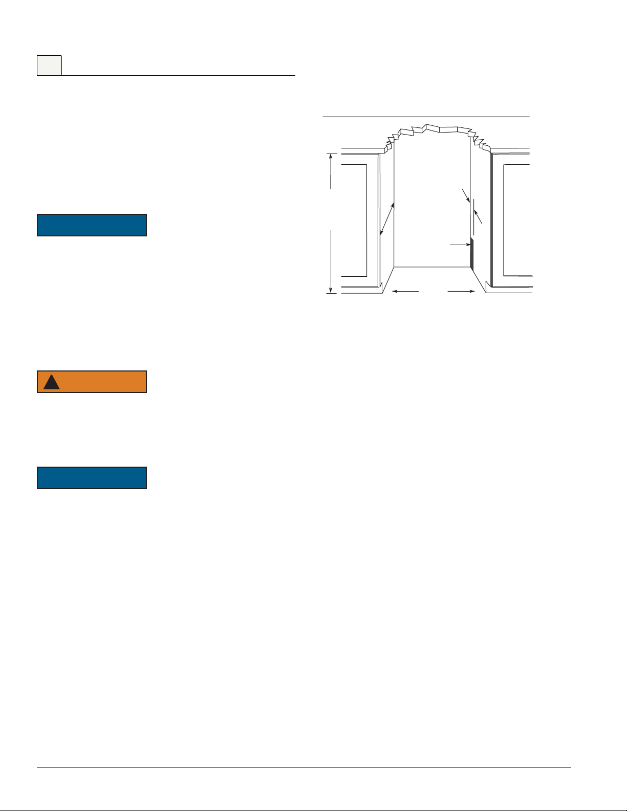
610 mm
450 mm
860 mm
to
886 mm
Preferred location for
3045CLR drain, water
line and receptacle is
in adjacent cabinet.
16 mm
Your U-Line product has been designed exclusively for a built-in
installation. When built-in, your unit does not require additional air
space for top, sides, or rear. However, the front grille must NOT be
obstructed.
The Modular 3000 Series units are engineered with a variety of
adjustment features to help ensure a seamless installation. adjustable
doors, leveling legs and grille will assist in fine tuning the installation.
All 3000 Series models fully integrate into overlay/face frame, inset or
European/frameless cabinet styles.
• Unit can NOT be installed behind a closed cabinet door.
• For cabinet depths less than 620 mm, electrical socket
MUST be located in the adjacent cabinet or recessed in
the wall. The power cord length is 180 cm.
• U-Line products are designed and manufactured to be
seamlessly installed in the specified cut-out openings
shown, and variance to the floors or cabinetry must be
accounted for in your installation.
Electrical Specifications
Cut-Out Dimensions
3045CLR Model
SHOCK HAZARD — Electrical Grounding Required.
• Never remove the round grounding prong from the plug
and never use a two-prong grounding adapter.
• Never use an extension cord to connect power to the
unit.
Electrical installation must observe all state and local codes.
This unit requires connection to a grounded (three-prong),
polarized receptacle that has been placed by a qualified
electrician.
The unit requires a grounded and polarized 230 VAC, 50 Hz, 8A
power supply (normal household current). An individual, properly
grounded branch circuit or circuit breaker is recommended. GFCI
(ground fault circuit interrupter) is usually not required for fixed
location appliances and is not recommended for your unit because a
GFCI could be prone to nuisance tripping. However, be sure to
consult your local codes.
See Cut-Out Dimensions for recommended receptacle location.
4 u-line.com
 Loading...