

Page 1
Pour le français, consulter les pages 9-12.
Para Español, vea páginas 5-8.
π H-5655
CEILING FAN
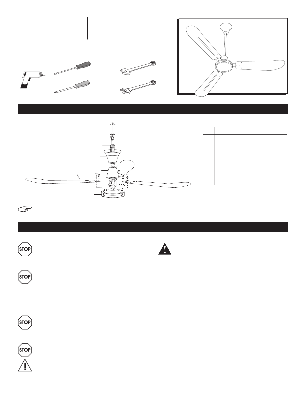
TOOLS NEEDED
Flat Head Screwdriver
Power Drill
5
1-800-295-5510
uline.com
3
1
4
2
6
9/16" Wrench
3/8" WrenchPhillips Head Screwdriver
PARTS
REPLACEMENT PARTS LIST
# DESCRIPTION
1 18" Downrod with Rubber Support
2 Lower Canopy
3 J Hook
4 Upper Canopy
5 Blade
6 Capacitor
7 Motor Housing With Yoke
7
NOTE: After opening carton, look for concealed damage. If
concealed damage is found, immediately file claim with carrier.
SAFETY
WARNING! Disconnect power supply before
wiring connections are made to prevent
possible electric shock or damage to
equipment.
WARNING! Do not operate any fan with a
damaged cord or plug. Do not run cord under
carpeting. Do not cover cord with throw rugs,
runners or similar coverings. Do not route cord
under furniture or appliances. Arrange cord
away from traffic area and where it will not be
tripped over.
WARNING! Read and follow instructions
carefully. Failure to comply with instructions
could result in fire, electric shock, injury to
persons and/or damage to equipment.
WARNING! Do not use an extension cord with
this fan.
CAUTION! Follow all maintenance procedures
enclosed.
1. All wiring should conform to the National Electrical
2. Do not mount in an area that will allow the ceiling
3. Make certain the entire installation is grounded as a
4. Do not exceed maximum amperage rating of the
5. When wiring an electrical appliance or device,
6. Suitable for use with solid state speed control.
DANGER! Failure to properly ground unit could
result in severe electrical shock or death.
Code ANSI/NFPA 70-1999 (NEC) in the United States,
CEC and local regulations.
fan to come in contact with moisture.
precaution against possible electrical shock.
ceiling fan, as overloading can result in damage to
ceiling fan.
follow all electrical and safety codes, as well as the
most recent NEC, CEC and local regulations and the
Occupational Safety and Health Act (OSHA).
PAGE 1 OF 12 0819 IH-5655
Page 2
INSTALLATION
This model is manufactured with a cord and a molded
three prong electrical plug, which can be installed
directly into an electrical outlet.
NOTE: For installation to open web steel joist,
use the threaded J hook as supplied. For wood
joist construction, use J hook with lag threads
(not included). For attachment in concrete,
drill concrete anchors into the concrete, as
applicable to NEC, CEC and local regulation.
WARNING! To reduce the risk of personal
injury, do not bend the blade brackets when
installing the brackets, balancing the blades or
cleaning the fan. Do not insert foreign objects
in between rotating fan blades.
1. Prior to installation, ensure all pre-installed set screws,
cotter pins and locknuts are tight and secure.
2. Slide lower canopy (2) down to the rubber gasket to
create a tight seal. Tighten set screw.
3. Wind one nut down to bottom of J hook (3) towards
the curve. Add a lock washer and then flat washer
on top of the nut.
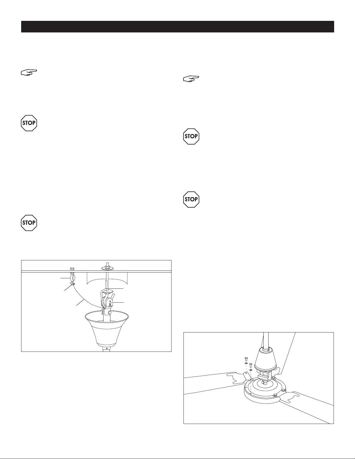
WARNING! Make certain crimps on safety loop
are
secure (See Figure 1). Make certain safety
cable
is attached properly to hook or structural
member.
Failure to comply with instructions
could result in personal injury and/or property
damage.
Safety Hook
Safety Loop
Safety Cable
J Hook Support
Support Bracket
5. Drill a 1/2" pilot hole for J hook. Put J hook (3) through
pilot hole in joist. Add flat washer and then lock
washer and nut. Do not tighten completely until fan
is put in place on J hook.
NOTE: A lubricant should not be used on the
single mounting screw. Pilot hole should be
drilled no larger than the minor diameter of the
mounting screw threaded. At least 1⁄" (38mm)
of the threaded part of the mounting screw
should be secured into a structural joist to
provide secure mounting.
IMPORTANT! If a shorter downrod is required,
read steps on page 3.
6. Loosen set screw on upper canopy (4) on fan
downrod (1) and lower the canopy to make room to
place rubber grommet onto mounting J hook.
7. Tighten top nut on J hook to raise fan into proper
installation position.
WARNING! When installed properly, the blades
will hang 10' above the floor level. It is critical
that the J hook and nut adjustment are done
so that the blades will be a minimum 12" from
the ceiling. If your ceiling is less than 12', then
the hook and downrod must be recessed into
the ceiling so that the blades are mounted 10'
above the floor level to meet OSHA standards.
8. Raise upper canopy (4) up the downrod to cover
hook. Leave 1/8" gap between upper canopy (4)
and hanging surface so downrod does not move
off center, which could make fan wobble or vibrate
and transmit motor noise to ceiling surface. Tighten
set screw on upper canopy (4).
9. Attach blades (5) to motor housing (7) with blade
bolts already installed in motor housing. The blade
should be positioned below the blade arm bracket
when attaching to the motor to get proper air flow
and direction. (See Figure 2)
Figure 1
4. Drill a 5/32" pilot hole for safety hook (See Figure 1)
within a 12" radius of J hook (3) for fan. Wind one
nut down to bottom of safety hook towards the loop.
Add a lock washer and slide safety hook through
pilot hole. Slide lock washer on top side of the safety
hook and add nut. Tighten so lock washers on top
and bottom of the structure are secure.
Figure 2
PAGE 2 OF 12 0819 IH-5655
Page 3
INSTALLATION CONTINUED
CHANGING TO SHORTER DOWNROD:
1. Loosen and remove bolt, cotter pin and nut on the
fan downrod support bracket. (See Figure 1)
2. Slide upper canopy (4) and lower canopy (2) off of
the downrod (1) and over the wires and safety cable.
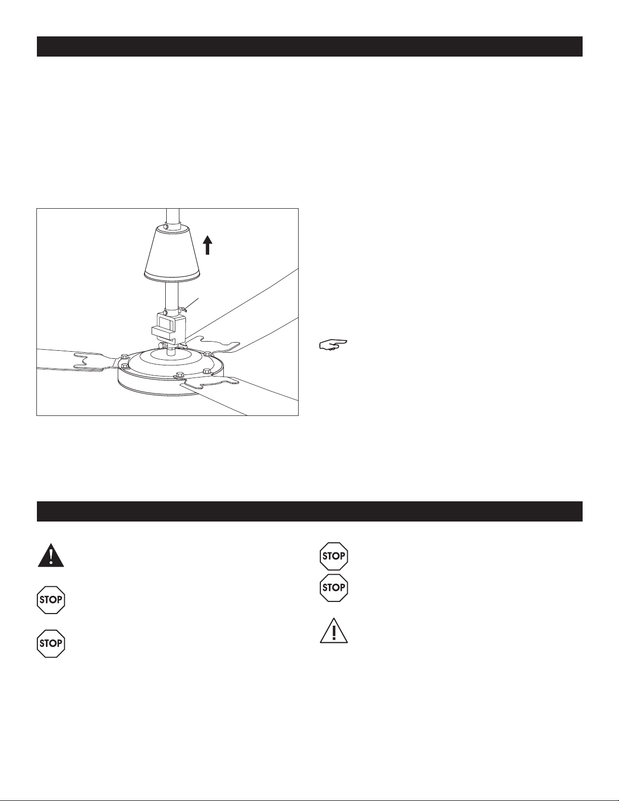
3. Loosen set screw and remove cotter pin at the motor
and slide the downrod (1) over the wires and safety
cable. (See Figure 3)
Figure 3
Cotter Pin
4. Take the shorter downrod and start to reverse steps
three to one.
6. Insert bolt through the yoke and downrod, making
certain you do not damage the wires. Once the bolt
is in place, re-insert the cotter pin and bend the
longer side backwards so it will not slide out.
7. Tighten the set screws to 10 foot/lbs. of torque.
8. Slide the lower canopy (2) over the wires, safety
cable and downrod (1) until it sits on top of the yoke,
and tighten the set screw.
9. Slide the upper canopy (4) over the wires, safety
cable and downrod, and do not tighten the set
screw.
10. Attach rubber grommet and support bracket to the
top of the downrod using bolt, cotter pin and nut.
Make certain you do not damage the wires inside
the downrod. Tighten the nut to 10 foot/lbs. of torque,
re-insert the split pin and bend the longer side
backwards so the pin will not slide out.
11. Return to the installation instructions.
NOTE: The shorter downrod, when installed
properly, is a minimum 10' above the floor level.
It is critical that the J hook and nut
are done so that the blades will be a minimum
12" from the ceiling. If your ceiling is less
than 12', then the hook and downrod must be
recessed into the ceiling so that the blades
are mounted 10' above the floor level to meet
OSHA standards.
adjustment
5. Slide the shorter downrod over the wire and safety
cable and insert into yoke.
MAINTENANCE
DANGER! Always disconnect the power supply
before servicing the ceiling fan or working with
the unit for any reason.
WARNING: Parts replacement and
troubleshooting should be performed only by
qualified personnel.
WARNING: Do not place fingers or objects in
the ceiling fan while motor is connected to the
power source.
WARNING: Do not attach foreign objects to the
blades of the ceiling fan.
WARNING: Do not use gasoline, benzene,
thinner, harsh cleaners, etc., which are
dangerous and will damage the ceiling fan.
CAUTION! If you see noticeable vibration,
wobbling or wear, the fan should be removed
from service and repaired or replaced by
a qualified maintenance technician or
electrician.
PAGE 3 OF 12 0819 IH-5655
Page 4
TROUBLESHOOTING
DANGER! Always disconnect the power supply
before servicing the ceiling fan or working with
the unit for any reason.
TROUBLESHOOTING
OPERATING ISSUE RECOMMENDATIONS
Fan will not start.
Fan is too fast/slow.
Fan makes noise.
a) Check fuses and circuit breakers.
b) Check wire connections to fan.
c) Check wiring connection in lower canopy.
d) Check voltage at fan connection.
a) Check voltage at fan connection.
b) Blades must be attached to motor to reduce the speed.
c) Adjust the trim set screw in fan wall control if using optional wall control.
If minimum setting is too low the fan may shut off with voltage fluctuations.
Increase minimum.
a) Check motor case to make certain all visible screws are snug.
b) Check to make certain that all blade bracket screws are tight.
c) Check for labels or wire nuts that could be rubbing.
d) All ceiling fans may have a slight motor noise known as the "60 cycle hum" when
used with solid state infinite speed controls, especially on lower speeds. This hum
will not affect the fan performance.
e) Make certain upper canopy is at least 1/8" from ceiling.
f) Allow a 30 day break-in period, which normally eliminates any residual noise other
than a), b), c), d) or e).
WARNING: Parts replacement and
troubleshooting should be performed only by
qualified personnel.
π
Fan wobbles.
CHICAGO • ATLANTA • DALLAS • LOS ANGELES • MINNEAPOLIS • NYC/PHILA • SEATTLE • MEXICO • CANADA
a) Check that all blade brackets are screwed firmly to motor case.
b) Check distance from tip of blades to ceiling. If blades get bent during installation,
you must re-adjust them so that all blades travel on same plane. Gently bend up
or down until all distances are the same.
c) Make certain upper canopy is 1/8" from ceiling.
d) Make certain that hanging hooks are secured tightly to ceiling.
e) Run fan without blade. If motor does not wobble, then motor is not defective,
but the blades may be bent.
1-800-295-5510
PAGE 4 OF 12 0819 IH-5655
uline.com
Page 5

π H-5655
VENTILADOR
DE TECHO
HERRAMIENTAS NECESARIAS
800-295-5510
uline.mx
Taladro Eléctrico
NOTA: Una vez que haya abierto la caja de cartón, busque
daños ocultos. Si encuentra daños ocultos, presente un reclamo
inmediatamente a la empresa de transporte.
Desarmador de
Cabeza Plana
5
7
Llave de 9/16"
Llave de 3/8"Desarmador de Cruz
PARTES
3
1
4
2
6
LISTA DE PIEZAS DE REPUESTO
# DESCRIPCIÓN
1 Varilla Descendente de 45.7 cm
(18") con Soporte de Goma
2 Dosel Inferior
3 Gancho en J
4 Dosel Superior
5 Aspa
6 Condensador
7 Carcasa del Motor con Horquilla
SEGURIDAD
¡ADVERTENCIA! Antes de hacer alguna
conexión, desconecte el suministro de
electricidad para evitar posibles descargas
eléctricas o daños al equipo.
¡ADVERTENCIA! No ponga en funcionamiento
ningún ventilador que presente un cordón
o conector dañado. No pase el cordón por
debajo de alfombras, tapetes, rollos o elementos
cobertores similares. No pase el cordón por
debajo de muebles o electrodomésticos.
Coloque el cordón lejos de la zona de paso, en
un lugar donde no se pueda tropezar con él.
¡ADVERTENCIA! Lea y siga las instrucciones
atentamente. No cumplir estas instrucciones
podría ocasionar incendios, descargas
eléctricas, lesiones personales y/o daños al
equipo.
¡ADVERTENCIA! No use una extensión eléctrica
con este ventilador.
¡PRECAUCIÓN! Siga todos los procedimientos
de mantenimiento que se indican.
PAGE 5 OF 12 0819 IH-5655
1. Todo el cableado deberá cumplir con el Código
2. No lo instale en una zona en la que el ventilador de
3. Asegúrese de que la instalación completa esté
4. No sobrepase el amperaje máximo establecido
5. Cuando haga la instalación de un
6. Apto para su uso con un control de velocidad de
¡PELIGRO! El no aterrizar la unidad
debidamente, puede ocasionar descargas
eléctricas graves o la muerte.
Eléctrico Nacional (NEC) ANSI/NFPA 70-1999 de los
Estados Unidos, CEC y las normativas locales.
techo pueda entrar en contacto con humedad.
aterrizada como precaución para evitar posibles
descargas eléctricas.
para el ventilador de techo, ya que una
sobrecarga podría dañar el ventilador de techo.
electrodoméstico o dispositivo eléctrico, siga todos
los códigos eléctricos y de seguridad, así como las
normativas NEC, CEC y locales más recientes y la
Ley de Seguridad y Salud Ocupacional de Estados
Unidos (OSHA).
estado sólido.
Page 6

INSTALACIÓN
Gancho de
Seguridad
Bucle de
Seguridad
Cable de Seguridad
Soporte de Respaldo
Soporte de Gancho
en J
Este modelo ha sido fabricado con un cordón y un
enchufe eléctrico moldeado de tres clavijas, que se puede
insertar directamente en el enchufe.
NOTA: Para instalaciones en vigas de acero
de alma abierta, use el gancho en J roscado
que se suministra. En construcciones con vigas
de madera, use el gancho en J con tirafondos
roscados (no se incluyen). Para instalaciones en
concreto, inserte anclajes para concreto en el
concreto, de acuerdo con lo establecido en las
normativas NEC, CEC y locales.
¡ADVERTENCIA! Para reducir el riesgo de lesiones
personales, no doble los soportes de las aspas
al instalar los soportes, equilibrar las aspas o
limpiar el ventilador. No inserte objetos extraños
entre las aspas giratorias del ventilador.
1. Antes de la instalación, asegúrese de que todos
los tornillos de ajuste, los pasadores de chaveta y
las tuercas de seguridad que ya vienen instalados
estén bien apretados.
por la parte superior del gancho de seguridad
y añada una tuerca. Apriete de manera que las
rondanas de seguridad de la parte superior e
inferior de la estructura estén bien fijadas.
5. Taladre un orificio piloto de 1/2" para el gancho
en J. Inserte el gancho en J (3) a través del orificio
piloto de la viga. Añada una rondana plana y
luego una rondana de seguridad y una tuerca. No
apriete completamente hasta que el ventilador esté
bien colocado en su lugar en el gancho en J.
NOTA: No utilice ningún lubricante en el tornillo de
montaje único. El orificio piloto deberá taladrarse
de forma que no sea mayor que el diámetro
menor del tornillo de montaje enroscado. Al
menos 38 mm (1⁄") de la parte roscada del
tornillo de montaje deberá fijarse bien a la viga
estructural para que la instalación sea segura.
¡IMPORTANTE! Si se requiere una varilla
descendente más corta, lea los pasos
detallados en la página 3.
2. Deslice el dosel inferior (2) hacia abajo hasta la
junta de goma para crear un sello hermético. Ajuste
el Tornillo de Ajuste.
3. Enrosque una tuerca hasta el fondo del gancho en
J hacia la curva. Añada una rondana de seguridad
y luego una rondana plana encima de la tuerca.
¡ADVERTENCIA! Asegúrese de que las muescas
del bucle de seguridad están aseguradas
(Vea Diagrama 1). Asegúrese de que el cable
de seguridad
al elemento estructural.
esté bien fijado al gancho o
No cumplir estas
instrucciones podría ocasionar lesiones
personales y/o daños a la propiedad.
Diagrama 1
6. Afloje el tornillo de ajuste del dosel superior (4) de la
varilla descendente del ventilador (1) y baje el dosel
para hacer sitio para colocar un ojal de goma en
el gancho en J de montaje.
7. Apriete la tuerca superior del gancho en J para
elevar el ventilador hasta la posición de instalación
adecuada.
¡ADVERTENCIA! Cuando está correctamente
instalado, las aspas colgarán 3 m (10') por
encima del nivel del piso. Es esencial que
el ajuste del gancho en J y de la tuerca se
hagan de manera que las aspas queden a un
mínimo de 30.5 cm (12") del techo. Si la altura
de su techo es inferior a 3.7 m (12'), el gancho
y la varilla descendente deberán empotrarse
en el techo de manera que las aspas queden
3 m (10') por encima del nivel del piso para
cumplir con la normativa OSHA.
8. Eleve el dosel superior (4) por la varilla descendente
para cubrir el gancho. Deje un espacio de 3 mm (1/8")
entre el dosel superior (4) y la superficie de colgado
de manera que la varilla descendente no se mueva
del centro, ya que esto podría ocasionar que el
ventilador oscile o vibre y transmita el ruido del
motor a la superficie del techo. Apriete tornillo de
ajuste del dosel superior (4).
4. Taladre un orificio piloto de 5/32" para el gancho
de seguridad (Vea Diagrama 1) en un radio de
30.5 cm (12") del gancho en J (3) para el ventilador.
Enrosque una tuerca hasta el fondo del gancho en
J hacia la curva. Añada una rondana de seguridad
y deslice el gancho de seguridad a través del
orificio piloto. Deslice una rondana de seguridad
PAGE 6 OF 12 0819 IH-5655
9. Fije las aspas (5) a la carcasa del motor (7) con los
pernos para aspas que ya vienen instalados en la
carcasa del motor. Las aspas deberán posicionarse
debajo del soporte del brazo del motor al fijarlo
al motor para permitir un flujo y dirección del aire
apropiados. (Vea Diagrama 2)
Page 7

CONTINUACIÓN DE INSTALACIÓN
Pasador de
Chaveta
Diagrama 2
CAMBIAR A UNA VARILLA DESCENDENTE MÁS CORTA:
1. Afloje y quite el perno, el pasador de chaveta
y la tuerca del soporte de respaldo de la varilla
descendente del ventilador. (Vea Diagrama 1)
2. Deslice el dosel superior (4) y el dosel inferior (2)
para sacarlos de la varilla descendente (1) y por
encima del cableado y del cable de seguridad.
3. Afloje el tornillo de ajuste y quite el pasador de
chaveta del motor y deslice la varilla descendente
(1) por encima del cableado y del cable de
seguridad. (Vea Diagrama 3)
Diagrama 3
4. Tome la varilla descendente más corta y comience
a seguir los pasos del uno al tres en orden inverso.
5. Deslice la varilla descendente más corta por
encima del cableado y del cable de seguridad e
insértela en la horquilla.
6. Inserte un perno a través de la horquilla y la varilla
descendente, asegurándose de no dañar el
cableado. Una vez que haya colocado el perno en su
lugar, vuelva a colocar el pasador de chaveta y doble
el lado más largo hacia atrás de manera que éste no
se deslice y se salga.
7. Apriete el tornillo de ajuste a 10 pies/lbs.
8. Deslice el dosel inferior (2) por encima del
cableado, el cable de seguridad y la varilla
descendente (1) hasta que quede encajado
encima de la horquilla y apriete el tornillo de ajuste.
9. Deslice el dosel superior (4) por encima del
cableado, el cable de seguridad y la varilla
descendente y no apriete el tornillo de ajuste.
10. Fije el ojal de goma y el soporte de respaldo a la
parte superior de la varilla descendente usando
un perno, un pasador de chaveta y una tuerca.
Asegúrese de no dañar el cableado dentro de la
varilla descendente. Apriete la tuerca a 6.71 m/kg
(10 pies/lbs.) del par de torsion, vuelva a insertar el
pasador partido y doble el lado más largo hacia
atrás de manera que el pasador no se deslice y se
salga.
11. Vuelva a las instrucciones de instalación.
NOTA: Cuando está correctamente instalada, la
varilla descendente más corta está a un mínimo
de 3 m (10') por encima del nivel del piso. Es
esencial que el ajuste del
la tuerca se hagan de manera que las aspas
queden a un mínimo de 30.5 cm (12") del techo.
Si la altura de su techo es inferior a 3.7 m (12'),
el gancho y la varilla descendente deberán
empotrarse en el techo de manera que las
aspas queden 3 m (10') por encima del nivel
del piso para cumplir con la normativa OSHA.
gancho en J y de
MANTENIMIENTO
¡PELIGRO! Desconecte siempre el suministro
de electricidad antes de realizar tareas de
mantenimiento en el ventilador o trabajar con la
unidad por cualquier motivo.
ADVERTENCIA: El reemplazo de piezas y la
solución de problemas deberá llevarse a cabo
únicamente por personal cualificado.
ADVERTENCIA: No inserte los dedos o cualquier
objeto en el ventilador de techo cuando el motor
esté conectado a la fuente de alimentación.
PAGE 7 OF 12 0819 IH-5655
ADVERTENCIA: No fije objetos extraños a las aspas
del ventilador de techo.
ADVERTENCIA: No utilice gasolina, benceno,
diluyente, limpiadores agresivos, etc., que sean
peligrosos ya que dañarán el ventilador de techo.
¡PRECAUCIÓN! Si advierte vibración, oscilación
o desgaste notables, deje de utilizar el
ventilador y haga que un técnico o electricista
dé mantenimiento cualificado lo repare o
reemplace.
Page 8

SOLUCIÓN DE PROBLEMAS
¡PELIGRO! Desconecte siempre el suministro
de electricidad antes de realizar tareas de
mantenimiento en el ventilador o trabajar con
la unidad por cualquier motivo.
SOLUCIÓN DE PROBLEMAS
PROBLEMA DE FUNCIONAMIENTO
El ventilador no se
pone en marcha.
El ventilador
funciona
demasiado deprisa/
despacio.
El ventilador hace
ruido.
RECOMENDACIONES
a) Compruebe los fusibles y los disyuntores.
b) Compruebe las conexiones de los cables al ventilador.
c) Compruebe las conexiones de los cables del dosel inferior.
d) Compruebe el voltaje en la conexión del ventilador.
a) Compruebe el voltaje en la conexión del ventilador.
b) Las aspas deben estar fijadas al motor para reducir la velocidad.
c) Ajuste el tornillo de ajuste del reborde del control de pared del ventilador si
está utilizando un control de pared opcional. Si la configuración mínima es
demasiado baja, el ventilador podría apagarse debido a las fluctuaciones del
voltaje. Incremente el mínimo.
a) Compruebe la carcasa del motor para verificar que todos los tornillos visibles
estén bien apretados.
b) Compruebe que los tornillos de soporte de las aspas estén bien apretados.
c) Compruebe si hay etiquetas adhesivas o tuercas de cables que pudieran estar
causando roce.
d) Todos los ventiladores de techo emiten un ligero ruido proveniente del motor
conocido como "el zumbido de los 60 ciclos" cuando se utilizan con controles de
velocidad infinitos de estado sólido, especialmente a velocidades reducidas. Este
zumbido no afectará al rendimiento del ventilador.
e) Asegúrese de que el dosel superior esté a una distancia de al menos 3 mm (1/8")
del techo.
f) Permita que transcurra un periodo de adaptación de 30 días, en curso del cual
habitualmente desaparecen los ruidos residuales con la excepción de lo indicado
en a), b), c), d) o e).
ADVERTENCIA: El reemplazo de piezas y la
solución de problemas deberá llevarse a cabo
únicamente por personal cualificado.
π
El ventilador oscila.
CHICAGO • ATLANTA • DALLAS • LOS ANGELES • MINNEAPOLIS • NYC/PHILA • SEATTLE • MEXICO • CANADA
a) Compruebe que todos los soportes de las aspas estén bien atornillados a la
carcasa del motor.
b) Compruebe la distancia que hay entre la punta de las aspas y el techo. Si las
aspas se doblan durante la instalación, deberá volver a ajustarlas de manera
que todas las aspas se muevan en el mismo plano. Dóblelas cuidadosamente
hacia arriba o hacia abajo hasta que todas las distancias sean iguales.
c) Asegúrese de que el dosel superior esté a una distancia de al menos 3 mm (1/8")
del techo.
d) Asegúrese de que los ganchos para colgar estén bien fijados al techo.
e) Haga funciona el ventilador sin las aspas. Si el motor no oscila, entonces el motor
no es defectuoso, pero puede ser que las aspas estén dobladas.
800-295-5510
PAGE 8 OF 12 0819 IH-5655
uline.mx
Page 9

π H-5655
VENTILATEUR DE
PLAFOND
OUTILS REQUIS
1-800-295-5510
uline.ca
Perceuse électrique
REMARQUE: Après avoir ouvert la boîte, vérifiez que le contenu n'as pas
subi de dommages dissimulés. Si vous constatez la présence de dommages
dissimulés, déposez immédiatement une réclamation auprès du transporteur.
Tournevis à tête plate
3
1
4
5
2
6
7
Clé de 9/16po
Clé de 3/8poTournevis cruciforme
PIÈCES
LISTE DES PIÈCES DE RECHANGE
N° DESCRIPTION
1 Tige de suspension de 45,7cm (18po)
avec support en caoutchouc
2 Couvercle inférieur
3 Crochet en J
4 Couvercle supérieur
5 Pale
6 Condensateur
7 Boîtier du moteur avec mandrin
SÉCURITÉ
AVERTISSEMENT! Coupez l'alimentation avant
ARRÊT
ARRÊT
ARRÊT
ARRÊT
PAGE 9 OF 12 0819 IH-5655
d'effectuer les raccordements électriques
afin de prévenir des chocs électriques ou des
dommages matériels.
AVERTISSEMENT! N'utilisez jamais de ventilateur
dont le cordon ou la fiche est endommagé. Ne
faites pas passer le cordon sous une moquette.
Ne placez pas le cordon sous une carpette,
un tapis de couloir ou tout autre revêtement
semblable. Ne faites pas passer le cordon
sous des meubles ou des appareils. Placez
le cordon dans un endroit où il ne présente
aucun risque de trébuchement, c'est-à-dire
hors des zones de circulation.
AVERTISSEMENT! Lisez et suivez attentivement les
instructions. Le défaut de suivre ces instructions
peut entraîner un incendie, un choc électrique,
des blessures corporelles ou des dommages
matériels.
AVERTISSEMENT! N'utilisez pas de rallonge avec
ce ventilateur.
MISE EN GARDE! Suivez toutes les procédures
d'entretien ci-jointes.
1. Tout câblage doit être conforme au Code national
2. N'installez pas le ventilateur dans un endroit où il
3. Assurez-vous que toute l'installation est mise à la
4. Évitez d'excéder l'intensité de courant maximale
5. Lors du câblage d'un appareil ou d'un dispositif
6. Convient à un usage avec une commande de
DANGER! Un appareil qui n'est pas
correctement mis à la terre peut entraîner un
choc électrique grave ou la mort.
de l'électricité des États-Unis ANSI/NFPA 70-1999
(CEN), au Code canadien de l'électricité et aux
règlementations locales.
risque d'être exposé à l'humidité.
terre pour prévenir tout risque de choc électrique.
du ventilateur de plafond. Une surcharge risque de
l'endommager.
électrique, respectez toutes les normes en matière
de sécurité électrique, ainsi que le plus récent
Code national de l'électricité, le Code canadien de
l'électricité, les règlementations locales et la Loi sur
la sécurité et la santé au travail (OSHA).
vitesse transistorisée.
Page 10

INSTALLATION
Crochet de
sécurité
Boucle de
sécurité
Câble de sécurité
Ferrure de support
Support de crochet
en J
Ce modèle est conçu avec un cordon et une fiche
électrique moulée à trois broches, qui peut s'installer
directement dans une prise électrique.
REMARQUE: Pour l'installation sur une poutrelle
à treillis en acier, utilisez le crochet en J fileté
fourni. Pour les constructions avec solives
en bois, utilisez un crochet en J avec filets
décalés (non compris). Pour l'installation dans
du béton, percez des trous dans le béton pour
la fixation d'ancrages, conformément au Code
national de l'électricité, au Code canadien de
l'électricité et à la règlementation locale.
AVERTISSEMENT! Pour réduire le risque de
ARRÊT
blessures corporelles, évitez de plier les
supports de pale lorsque vous installez les
supports, équilibrez les pales ou nettoyez le
ventilateur. N'insérez pas de corps étrangers
entre les pales du ventilateur en mouvement.
1. Avant de procéder à l'installation, assurez-vous
que les vis de réglage, les goupilles fendues et les
écrous freinés préinstallés sont bien serrés.
2. Abaissez le couvercle inférieur (2) sur le joint en
caoutchouc pour créer un joint étanche. Serrez la
vis de réglage.
3. Enfilez un écrou sur la partie inférieure du crochet en
J (3), vers la courbe. Posez une rondelle de blocage,
puis une rondelle plate par-dessus l'écrou.
AVERTISSEMENT! Assurez-que vous le sertissage
ARRÊT
effectué au niveau de la boucle de sécurité
est bien solide et sécuritaire. (Voir Figure 1)
Assurez-vous que le câble de sécurité
est
fixé correctement au crochet ou à un élément
structurel.
Le défaut de suivre ces instructions
peut entraîner des blessures corporelles ou des
dommages matériels.
Figure1
boucle. Posez une rondelle de blocage par-dessus
l'écrou, puis insérez le crochet de sécurité dans
l'avant-trou. Posez une rondelle de blocage du
côté supérieur du crochet de sécurité, puis ajoutez
l'écrou. Serrez de façon à ce que les rondelles de
blocage de chaque côté de la structure soient bien
fixées.
5. Percez un avant-trou de 13mm (1/2po) pour le
crochet en J. Insérez le crochet en J (3) dans l'avanttrou dans la solive. Ajoutez une rondelle plate, puis
une rondelle de blocage et un écrou. Ne serrez
complètement que lorsque le ventilateur sera
installé sur le crochet en J.
REMARQUE: Aucun lubrifiant ne doit être utilisé
sur la vis d'installation unique. L'avant-trou doit
être percé à une largeur qui n'excède pas
le plus petit diamètre de la vis d'installation
filetée. Une section d'au moins 38mm (1½po)
de la partie filetée de la vis d'installation doit
être fixée dans une solive afin d'assurer une
fixation sûre.
IMPORTANT! Si vous avez besoin d'une tige de
ARRÊT
suspension plus courte, lisez les étapes à la
pa ge 11.
6. Desserrez la vis de réglage sur le couvercle
supérieur (4) de la tige de suspension du ventilateur
(1) et abaissez le couvercle pour pouvoir glisser un
œillet en caoutchouc sur le crochet en J.
7. Serrez l'écrou supérieur sur le crochet en J pour
soulever le ventilateur à la position de montage
appropriée.
AVERTISSEMENT! Lorsqu'elles sont correctement
ARRÊT
installées, les pales seront suspendues à 3m
(10pi) au-dessus du niveau du plancher. Il est
essentiel de régler le crochet en J et l'écrou
de façon à ce que les pales soient à au moins
30,5cm (12po) du plafond. Si votre plafond
est plus bas que 3,6m (12pi), le crochet et la
tige de suspension doivent alors être encastrés
dans le plafond afin que les pales soient fixées
à 3m (10pi) au-dessus du niveau du plancher
pour respecter les normes de l'OSHA.
8. Soulevez le couvercle supérieur (4) le long de la tige
de suspension pour couvrir le crochet. Laissez un
espace de 3mm (1/8po) entre le couvercle supérieur
(4) et la surface de suspension de façon à ce que la
tige de suspension ne se décentre pas, ce qui pourrait
faire osciller ou vibrer le ventilateur et transmettre le
bruit du moteur à la surface du plafond. Serrez la vis
de réglage sur le couvercle supérieur (4).
4. Percez un avant-trou de 4mm (5/32po) pour le
crochet de sécurité (Voir Figure 1) se trouvant dans
un rayon de 30,5cm (12po) du crochet en J (3)
du ventilateur. Enfilez un écrou sur le crochet de
sécurité jusqu'à ce qu'il atteigne l'extrémité en
PAGE 10 OF 12 0819 IH-5655
9. Fixez les pales (5) au boîtier du moteur (7) à l'aide des
boulons de pale déjà installés dans le boîtier du moteur.
Lorsque vous installez les pales, veillez à ce que les
supports de pale soient orientés vers le haut pour que
l'air soit projeté et dirigé adéquatement. (Voir Figure 2)
Page 11

INSTALLATION SUITE
Goupille fendue
Figure2
UTILISATION D'UNE TIGE DE SUSPENSION PLUS COURTE:
1. Desserrez et retirez le boulon, la goupille fendue
et l'écrou de la ferrure de support de la tige de
suspension du ventilateur. (VoirFigure1)
2. Retirez le couvercle supérieur (4) et le couvercle
inférieur (2) de la tige de suspension (1) en les
soulevant au-dessus des fils et le câble de sécurité.
3. Desserrez la vis de réglage, retirez la goupille fendue
du moteur, puis retirez la tige de suspension en la
glissant au-dessus des fils et le câble de sécurité.
(VoirFigure3)
Figure3
4. Prenez la tige de suspension plus courte et suivez
les étapes 3 à 1, soit l'ordre inverse des étapes de
démontage.
5. Glissez la tige de suspension plus courte sur le fil et
le câble de sécurité, puis insérez-la dans le mandrin.
6. Insérez le boulon dans le mandrin et la tige de
suspension, tout en veillant à ne pas endommager
les fils. Lorsque le boulon est en place, réinsérez la
goupille fendue et pliez le côté le plus long vers
l'arrière pour l'empêcher de ressortir.
7. Serrez les vis de réglage à un couple de 13,6Nm
(10pi-lb).
8. Glissez le couvercle inférieur (2) sur les fils, le câble
de sécurité et la tige de suspension (1) jusqu'à ce
qu'il repose sur le dessus du mandrin, puis serrez la
vis de réglage.
9. Glissez le couvercle supérieur (4) sur les fils, le câble
de sécurité et la tige de suspension, mais ne serrez
pas la vis de réglage.
10. Fixez l'œillet en caoutchouc et la ferrure de support
à la partie supérieure de la tige de suspension à
l'aide d'un boulon, d'une goupille fendue et d'un
écrou. Veillez à ne pas endommager les fils à
l'intérieur de la tige de suspension. Serrez l'écrou
à un couple de 13,6Nm (10pi-lb), puis réinsérez
la goupille fendue et pliez le côté le plus long vers
l'arrière pour l'empêcher de ressortir.
11. Retournez aux instructions d'installation.
REMARQUE: Lorsqu'elle est correctement
installée, la tige de suspension plus courte sera
située à 3m (10pi) au-dessus du niveau du
plancher. Il est essentiel de régler le crochet
en J et l'écrou de façon à ce que les pales
soient à au moins 30,5cm (12po) du plafond. Si
votre plafond est plus bas que 3,6m (12pi), le
crochet et la tige de suspension doivent alors
être encastrés dans le plafond afin que les pales
soient fixées à 3m (10pi) au-dessus du niveau
du plancher pour respecter les normes de l'OSHA.
ARRÊT
ARRÊT
PAGE 11 OF 12 0819 IH-5655
ENTRETIEN
DANGER! Débranchez toujours l'alimentation
électrique avant de procéder à l'entretien
du ventilateur de plafond ou d'effectuer
quelconque travail sur celui-ci.
AVERTISSEMENT : Seuls les membres du
personnel qualifiés peuvent changer les pièces
et effectuer les travaux de dépannage.
AVERTISSEMENT: Ne placez jamais vos doigts
ou des objets dans le ventilateur de plafond
lorsque le moteur est raccordé à la source
d'alimentation.
ARRÊT
ARRÊT
AVERTISSEMENT: Ne fixez pas de corps
étrangers aux pales du ventilateur de plafond.
AVERTISSEMENT: N'utilisez jamais de l'essence,
du benzène, du diluant, de nettoyants forts,
etc. Ils sont dangereux et endommageront le
ventilateur de plafond.
MISE EN GARDE! Si vous constatez que le
ventilateur vibre, oscille ou présente des signes
d'usure, il doit être mis hors service et réparé,
ou remplacé par un technicien d'entretien
qualifié ou un électricien.
Page 12

DÉPANNAGE
DANGER! Débranchez toujours l'alimentation
électrique avant de procéder à l'entretien
du ventilateur de plafond ou d'effectuer
quelconque travail sur celui-ci.
DÉPANNAGE
PROBLÈME RECOMMANDATIONS
Le ventilateur ne
démarre pas.
Le ventilateur tourne
trop rapidement/
lentement.
Le ventilateur fait du
bruit.
a) Vérifiez les fusibles et les disjoncteurs.
b) Vérifiez la liaison des fils électriques au ventilateur.
c) Vérifiez le câblage en dessous du couvercle inférieur.
d) Vérifiez la tension au niveau du branchement du ventilateur.
a) Vérifiez la tension au niveau du branchement du ventilateur.
b) Les pales doivent être fixées au moteur pour réduire la vitesse.
c) Ajustez la vis de réglage dans la commande murale du ventilateur si vous
utilisez la commande murale en option. Si le réglage minimum est trop faible,
le ventilateur peut s'arrêter et présenter des variations de tension. Augmentez le
minimum.
a) Vérifiez le boîtier du moteur pour vous assurer que toutes les vis visibles sont bien
serrées.
b) Assurez-vous que toutes les vis se trouvant sur les supports de pale sont serrées.
c) Vérifiez si des étiquettes ou des capuchons de connexion provoquent des
frottements.
d) Tous les ventilateurs de plafond peuvent émettre un léger bruit de moteur connu
sous le nom de «bruit à cycle 60» lorsqu'ils sont utilisés avec des commandes de
vitesse infinie à semi-conducteur, en particulier aux vitesses inférieures. Ce bruit ne
diminue pas le rendement du ventilateur.
e) Assurez-vous que le couvercle supérieur se trouve à une distance d'au moins 3mm
(1/8po) du plafond.
f) Prévoyez une période de rodage de 30jours, qui élimine normalement tout bruit
résiduel autre que a), b), c), d) ou e).
ARRÊT
AVERTISSEMENT : Seuls les membres du
personnel qualifiés peuvent changer les pièces
et effectuer les travaux de dépannage.
π
Le ventilateur oscille.
CHICAGO • ATLANTA • DALLAS • LOS ANGELES • MINNEAPOLIS • NYC/PHILA • SEATTLE • MEXICO • CANADA
a) Vérifiez que tous les supports de pale sont fermement vissés au boîtier du moteur.
b) Vérifiez la distance qui sépare la pointe des pales du plafond. Si les pales se
courbent lors de l'installation, vous devez les réajuster afin que toutes les pales se
déplacent sur un même plan. Pliez les pales délicatement vers le haut ou vers le
bas jusqu'à ce qu'elles soient à égale distance.
c) Assurez-vous que le couvercle supérieur se trouve à une distance de 3mm (1/8po)
du plafond.
d) Assurez-vous que les crochets de suspension sont bien fixés au plafond.
e) Faites fonctionner le ventilateur sans les pales. Si le moteur n'oscille pas, cela
signifie que le moteur n'est pas défecteux. Or, il se peut que les pales soient
tordues.
1-800-295-5510
PAGE 12 OF 12 0819 IH-5655
uline.ca
 Loading...