

Page 1
Para Español, vea páginas 8-14.
Pour le français, consulter les pages 15-21.
H-5485
LOW PROFILE
DUMPING HOPPER
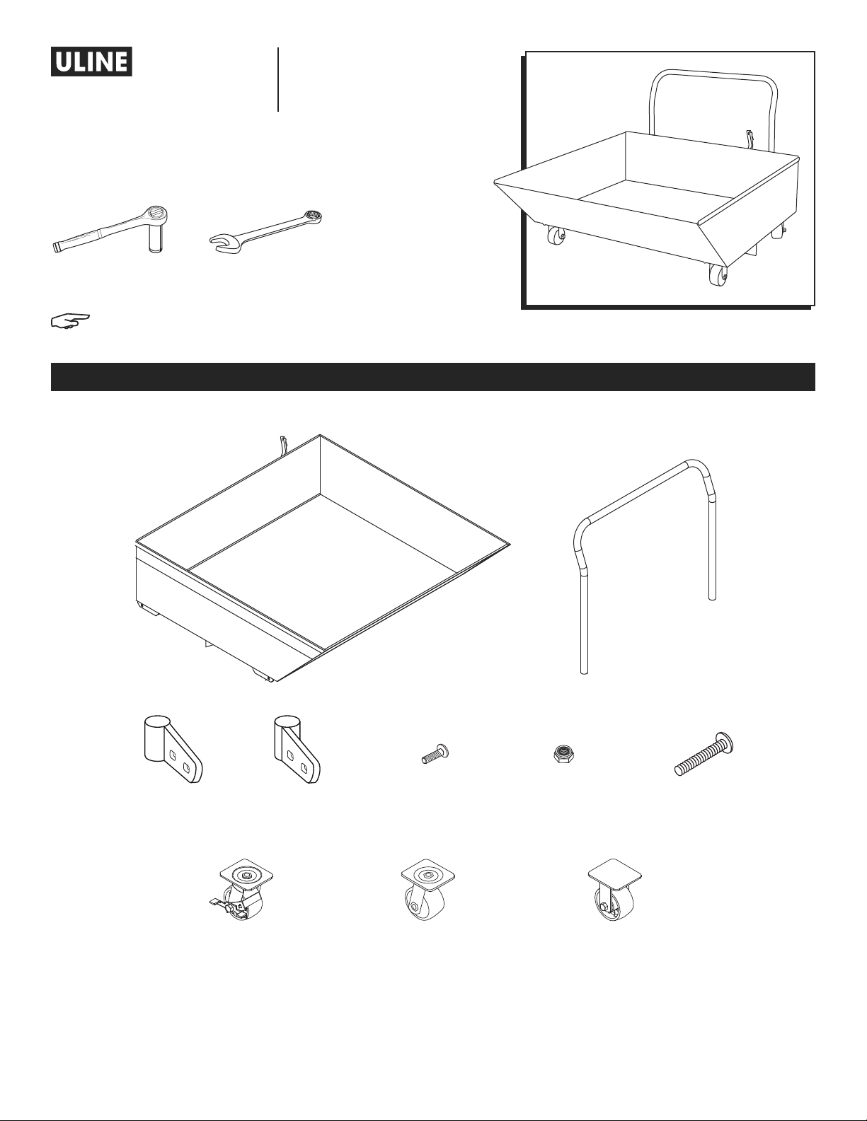
TOOLS NEEDED
9/16" Deep Well
Socket Wrench
NOTE: Gloves are recommended for assembly.
9/16" Wrench
1-800-295 -5510
uline.com
PARTS
Left Handle
Socket x 1
Right Handle
Socket x 1
Swivel Caster
with Brake x 1
Chute Assembly x 1
3/8" - 16 x 1⁄"
Handle Socket Bolt
x 4
Swivel Caster x 1 Rigid Caster x 2
3/8" Locknut x 8 3/8" - 16 x 5"
Handle x 1
Caster Bolt x 4
PAGE 1 OF 21 0621 IH-5485
Page 2
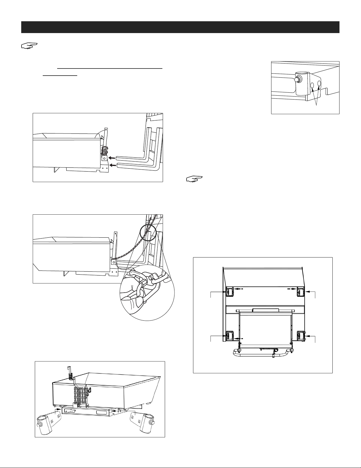
ASSEMBLY
NOTE: Uline recommends raising the hopper
on a forklift for assembly. If a forklift is
not available, tilt dumping hopper on its
side. Make sure hopper is stabilized before
proceeding.
RAISE HOPPER ON FORKLIFT
1. Drive lift truck forward until hopper's fork pockets
contact vertical legs of lift truck forks. (See Figure 1)
Figure 1
2. Wrap the safety chain around the fork carriage and
attach the quick link on the chain. There should be
no slack in the chain. (See Figure 2 and Figure 2a).
Figure 2
1. Insert two 3/8-16 x 1½" bolts through the two bolt
holes in the right socket bracket.
2. Slide the bolts through the
two bolt holes on the right
side of the base frame.
(See Figure 4)
3. Secure each bolt with a
3/8" locknut using a 9/16"
deep well socket wrench,
Figure 4
Bolt
but DO NOT TIGHTEN.
4. Repeat steps 1-3 to install the left socket bracket.
ATTACH HANDLE
1. Insert the handle legs into the sockets. Maneuver
handle legs into place until they are all the way into
the socket.
NOTE: Put handle legs into sockets evenly. Do
not put in one at a time.
2. Tighten the set screws on the back of the socket
brackets against the handle legs using a 9/16"
wrench.
ATTACH CASTERS
3. Raise forks to a comfortable
working height.
4. Unlock the latch and dump the
Figure 2a
hopper.
ATTACH HANDLE SOCKET BRACKETS
Attach the socket brackets on either side of the hopper
base. Right socket bracket is offset to the right. Left
socket is offset to the left. (See Figure 3)
Figure 3
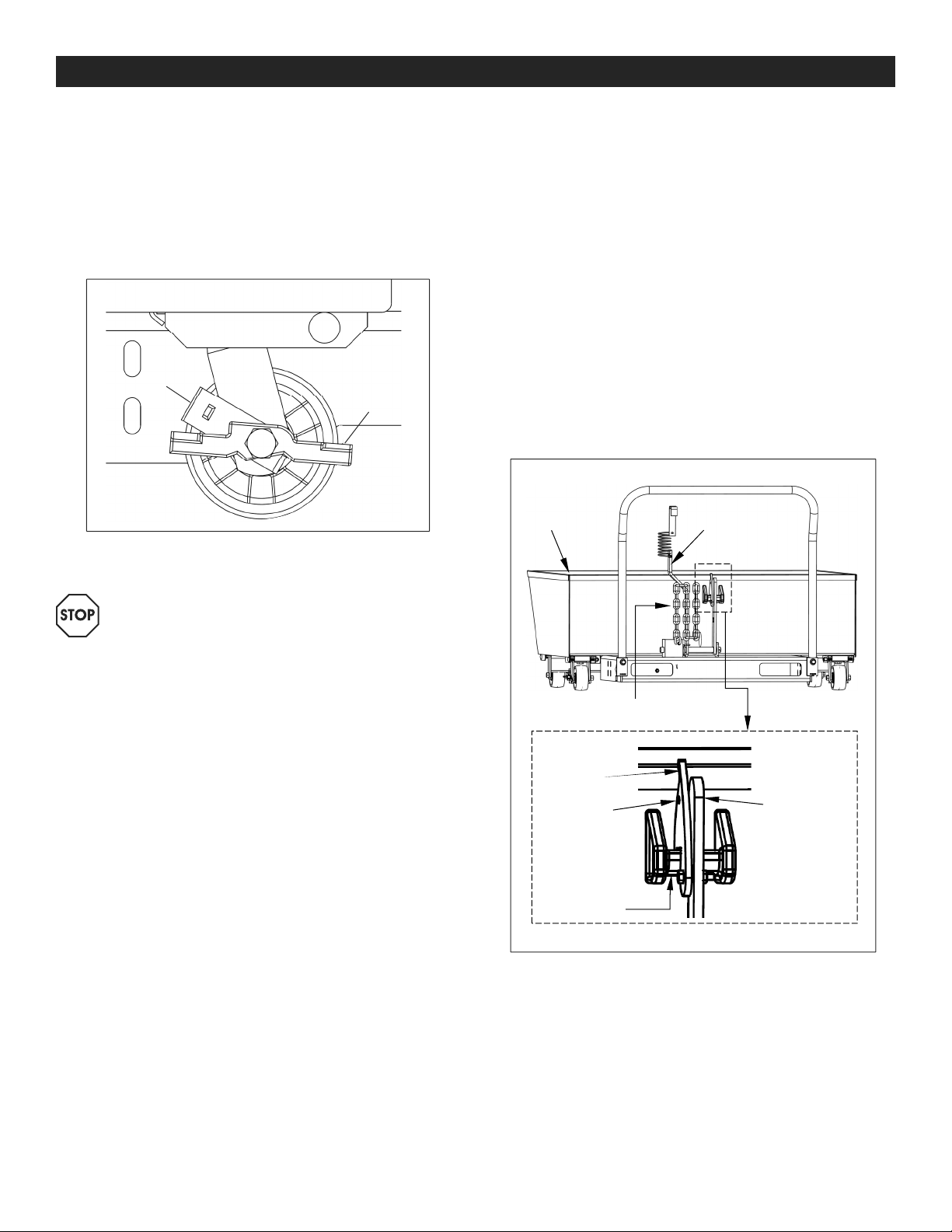
Install rigid casters on the front of the hopper and swivel
and swivel with brake casters on the back of the hopper
(See Figure 5).
Figure 5
Rigid
Caster
Swivel
Caster
Rigid
Caster
Swivel
Caster
with
brake
PAGE 2 OF 21 0621 IH-5485
Page 3
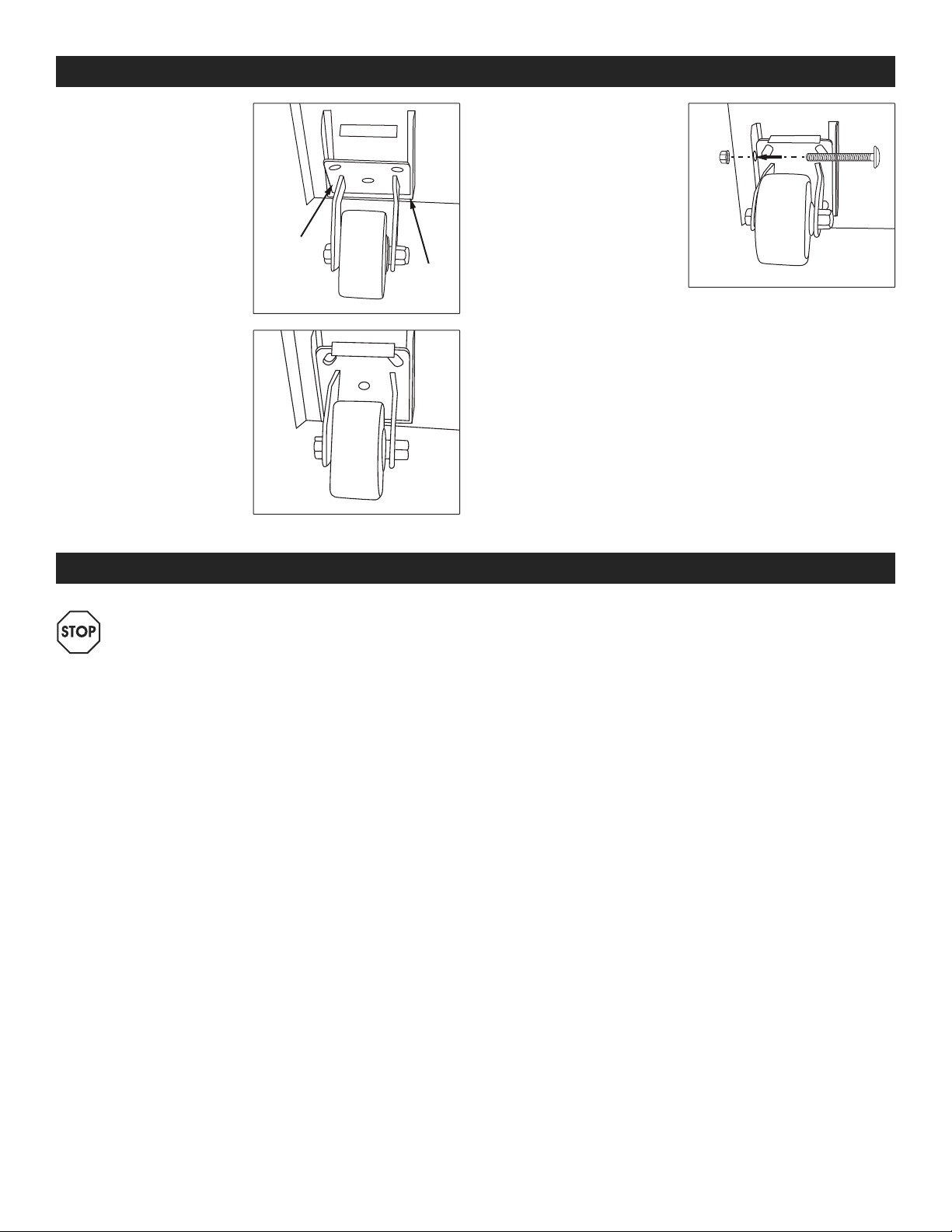
ASSEMBLY CONTINUED
1. Insert one edge of the
caster mounting plate
under the angled
bracket of the caster
mount. (See Figure 6)
2. Press the mounting
plate against the
underside of the
hopper. (See Figure 7)
Mounting
Plate
Figure 6
Figure 7
Angled
Bracket
3. Insert a 3/8-16 x 5" bolt
through the bolt holes
on the inside of the
caster mounting plate.
Secure the bolt with
a 3/8" locknut using a
9/16" wrench.
(See Figure 8)
4. Repeat steps 1-3 for
Figure 8
the remaining casters.
5. Tighten all locknuts.
REMOVE HOPPER FROM FORKLIFT
1. Slowly lower forks and disconnect safety chain.
2. Back lift truck away until forks are free of hopper's
fork pocket.
SAFETY
WARNING! Follow these safety instructions to
avoid any personal injury.
• Do not use a malfunctioning or structurally
damaged hopper. Examples of structural damage
include:
a. damage to the hopper release mechanism (that
allows the hopper to dump);
b. broken fork pocket(s);
c. damaged main connection pin; or
d. broken welds. Inspect the hopper before each
use according to the inspection instructions on
page 6. Do Not use the hopper unless it passes
every part of the inspection.
• DO NOT use the hopper if the safety chain is
damaged or absent.
• DO NOT lift the hopper until it is securely connected
to the carriage of the fork truck with the safety chain.
• DO NOT fill the hopper with a load weighing more
than its capacity (2,000 lb.).
• DO NOT stand beneath or travel under the hopper
at any time. Do not permit any person to stand
beneath or travel under the hopper.
• Hoppers with lifting lugs can be lifted with overhead
hoists and cranes. DO NOT lift a hopper unless the
chute is securely latched to the frame. The hopper
must not be able to rotate while it is suspended.
• DO NOT allow people to ride on or in the hopper.
• DO NOT use the hopper if any product label is
unreadable, damaged, or missing. Contact Uline
Customer Service at 1-800-295-5510 to order
replacement labels.
• Always apply proper (fork) lift truck operation
practices learned during your training program.
Before raising the hopper from the floor, tilt the (forklift)
mast toward the cab of the truck to ensure that the
hopper will not slide towards the tips of the forks.
• DO NOT modify the hopper in any way!
Modifications might make the hopper unsafe to use
and automatically void the limited warranty.
• DO NOT dump the hopper unless every person in the
vicinity is safely behind the forklift truck.
• DO NOT dump the hopper if the forklift is facing
down a slope. Only dump the hopper while parked
on a level surface.
• ALWAYS engage the caster brake when the hopper
is stationary or not in use.
PAGE 3 OF 21 0621 IH-5485
Page 4
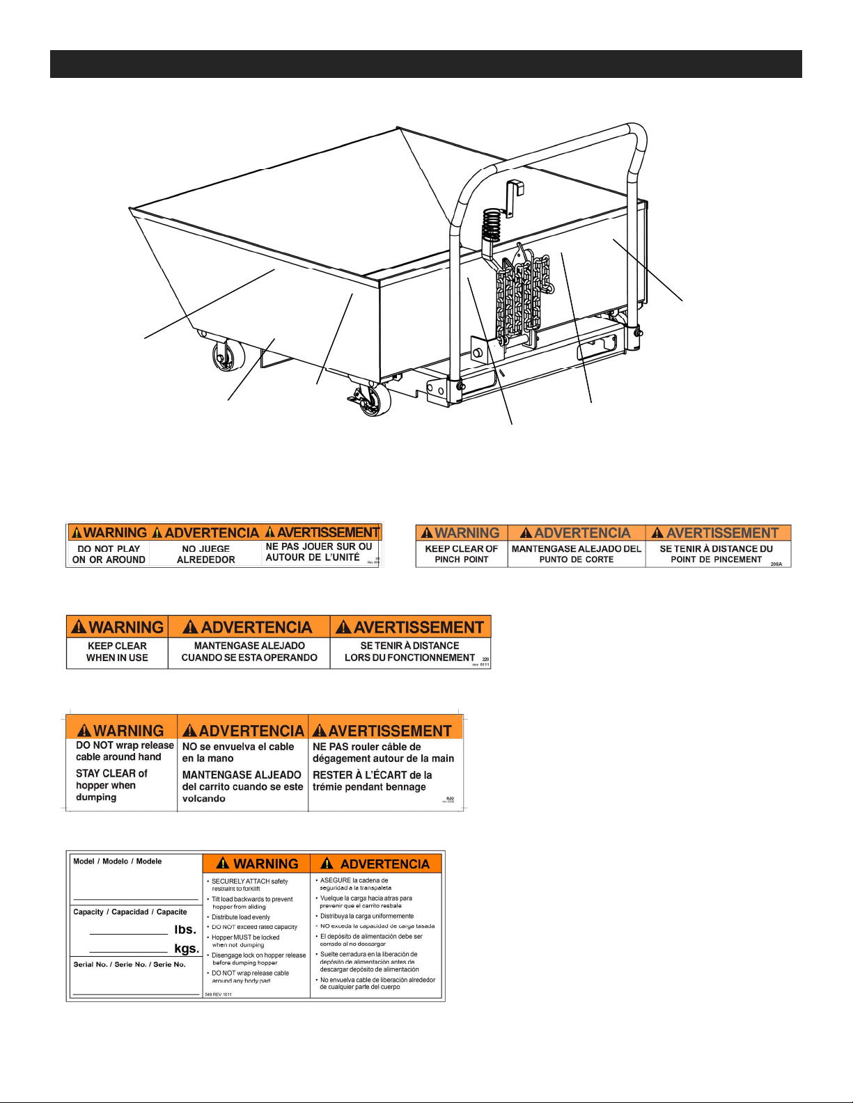
WARNING LABELS
E
B
A
A. Label 375 (both sides)
C. Label 220 (both sides)
D. Label 620
B
C
B
D
B. Label 208 (both sides & back)
E. Label 549
PAGE 4 OF 21 0621 IH-5485
Page 5
OPERATING INSTRUCTIONS
CASTER BRAKE
Each hopper has two swiveling casters in the rear, one
of which is equipped with a brake. (See Figure 9)
1. To engage the brake, press the brake lever down.
When the brake is engaged, the wheel will not rotate.
2. To disengage the brake, lift the brake lever up.
Figure 9
Brake
Brake
lever
LOADING
WARNING! Do not exceed the load rating or fill
the hopper above the top of the sides. Serious
personal injury (or property damage) could
result from overloading the hopper.
DUMPING
1. Mount the hopper on the forks of a lift truck and
secure it to the carriage with the safety chain. Wrap
the free end of the chain around the lift carriage;
then fasten the quick link to a link in the chain. The
chain must be taut (no slack) to prevent the hopper
from sliding on the forks.
2. Store the handle of the release cable within reach
of the forklift operator. For example, hook the cable
to the frame of the forklift cab. Make sure that there
is plenty of slack in the cable to avoid accidentally
releasing the chute.
3. The chute cannot dump unless the latch is unlocked.
To unlock the latch, pull the finger tab at the top
end of the latch lock bracket until the bracket
disengages the latch bar (See Figure 10)
Figure 10
Front end of
chute
Manual chute
release lever
Low profile hoppers are designed for indoor and
outdoor use in most industrial and commercial
settings. They should only be used to collect and dump
non-hazardous wastes.
1. Confirm the hopper chute is solidly latched to the
base frame before filling the chute with refuse.
2. When the hopper is stationary, engage the caster
brake.
Finger tab
Latch lock
bracket
Latch bar
Safety chain
Latch lever
PAGE 5 OF 21 0621 IH-5485
Page 6
OPERATING INSTRUCTIONS CONTINUED
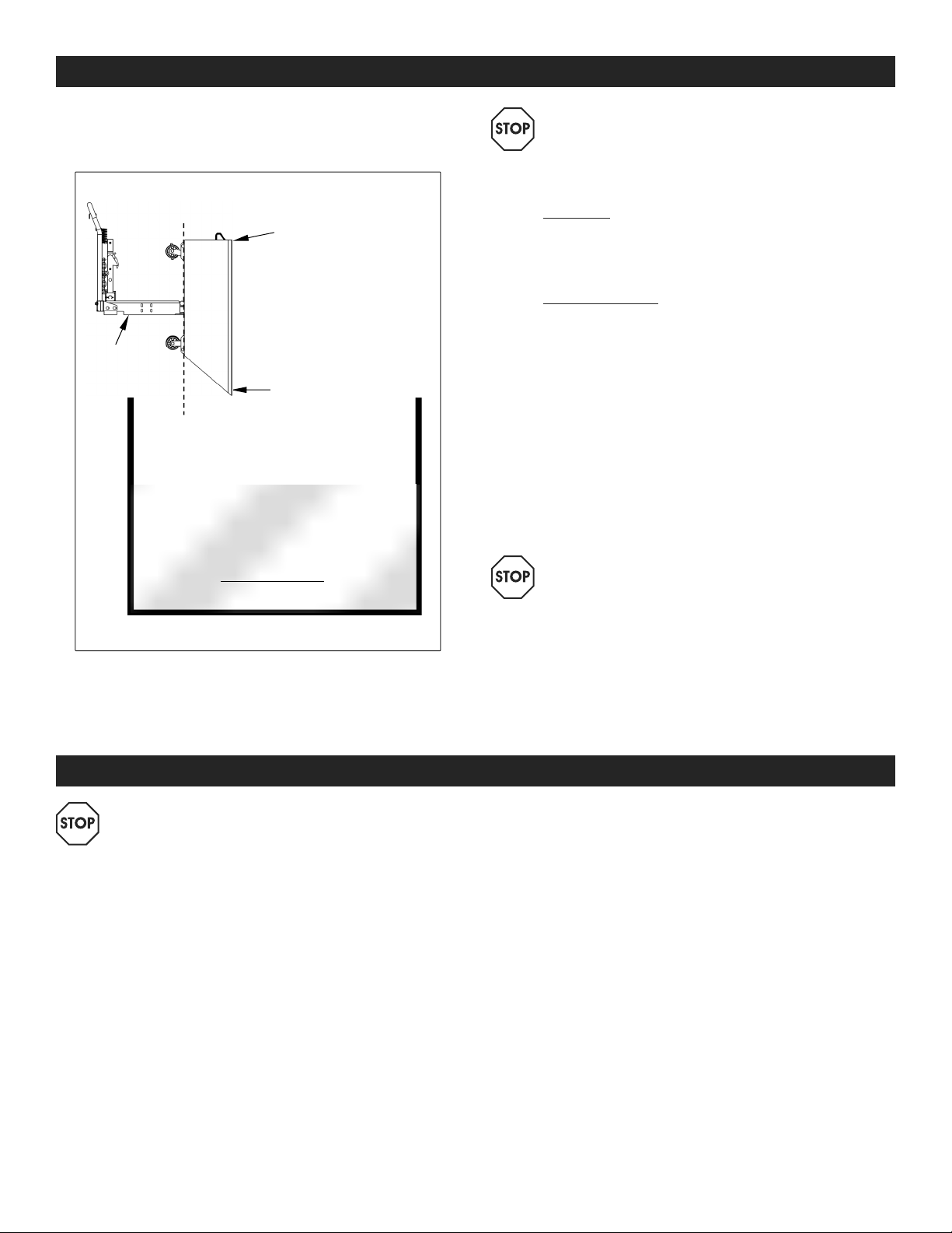
4. Raise the hopper above the dumpster and drive
forward until the dumping axis is clearly over the
inside of the dumpster (See Figure 11).
Fig u r e 11
Back end
of chute
Base
frame
Front end
of chute
Dumping
axis
Waste material
WARNING! DO NOT wrap the release cable
around your hand/fingers or attach the handle
to your clothing!
6. Latch the chute to the base.
a. Manually: Slowly lower the forks until the hopper
rests on the ground. The chute will pivot towards the
frame. Press the back end of the chute onto the
base until the latch lever engages the latch bar.
b. Using the forklift: Raise the fork tips by tilting the
forklift mast toward the cab. Then, back away
from the dumpster. Slowly lower the forks until the
front end of the chute contacts the top of the
side of the dumpster. Continue to slowly lower
the forks until the chute pivots onto the base
frame. You should hear the latch lever snap over
the latch bar. Confirm that the chute is securely
latched by raising the forks. The chute should not
rotate. If necessary, lower the forks completely
and manually latch the chute to the frame.
7. Lock the latch by reversing the process described in
step 3.
WARNING! DO NOT move the hopper until the
latch is locked!
5. Dump the contents of the hopper by releasing the
chute. To release the chute, pull the release cable.
The chute will pivot about the dump axis.
Dumpster (cross-section)
MAINTENANCE
WARNING! If an inspection reveals issues,
restore the hopper to normal operating
condition BEFORE using it again. DO NOT use
a structurally damaged hopper. Structural
damage includes but is not limited to,
cracked welds, warping or deformation of the
chute, pivot points, or the supporting frame,
particularly the fork pockets.
DAILY INSPECTION
Before each use, inspect the following components:
• Release cable – Look for fraying, birdcaging,
thinning.
• Hopper chute or base frame – Check for damage,
deformation, corrosion or severely rusted regions.
• Pivot points – As the chute rotates (after releasing
it), listen for unusual noise and watch for binding as
the chute rotates. Also look for distortion of the axle
points or axle receivers.
• Release/latch mechanisms – Test the chute release
mechanism (lock release, lever assembly). The
torsion spring should cause the lever assembly to
automatically recoil and firmly latch the chute to the
frame.
• Safety chain – Check the chain for damaged links
(broken, cracked, elongated).
PAGE 6 OF 21 0621 IH-5485
Page 7
MAINTENANCE CONTINUED
1
0
uline.com
MONTHLY INSPECTION
Inspect the following components at the least once per
month. Replace any component that is excessively worn
or no longer operates normally:
• Pivot points – Look for excessive wear, warping, or
other damage to the release lever pin, pin brackets,
axle pins and axle receivers. Listen for unusual
noises and watch for irregular movement. Remove
dirt and debris from areas that could affect the
hopper's dumping motion.
• Fasteners (bolt, locknuts, axle pins, cotter pins,
retaining rings) – Inspect for looseness and wear.
• Casters – Check for looseness, excessive wear or
damage to the casters, caster bearings, mounting
brackets and hardware. Confirm that the brake
functions properly.
• Release Mechanism – Verify the mechanisms
function properly:
a. Torsion spring firmly latches the lock release lever
assembly to the chute.
b. The latch lock bracket should seat on the latch
bar unless manually disengaged.
• Chute – Examine the chute. The structure should be
rigid and square without corroded holes or severely
rusted areas.
• Supporting frame – Examine the frame. It should be
rigid and square, welds should be intact and fork
pockets should be square and sound.
• Labels – All labels must be applied to the hopper
in the locations shown in the labeling diagram on
page 4.
WARNING! The end user should understand
the significant difference between necessary
adjustments and repairs, and modification.
Adjustments are simple corrections that restore
the hopper to normal operating condition,
such as tightening loose fasteners, or removing
dirt or other debris from the surface. Repairs
involve removing worn parts and installing new/
replacement parts.
A modification is a change that alters the
hopper from normal operating condition, such
as bending the frame or removing a part
or several parts. NEVER modify the hopper.
Modifications automatically void the Warranty
and might make the hopper unsafe to use.
c. Lever assembly pivots smoothly and securely
engages the latch bar.
-800-295-551
PAGE 7 OF 21 0621 IH-5485
Page 8

H-5485
TOLVA AUTOVACIABLE
DE PERFIL BAJO
HERRAMIENTAS NECESARIAS
800-295 -5510
uline.mx
Llave de Tubo de
Impacto Profundo de
9/16"
NOTA: Se recomienda usar guantes para el ensamble.
Llave Combinada
de 9/16"
PARTES
1 Ensamble de la Tolva
1 Asa
1 Soporte
Izquierdo con
Orificios para
el Asa
PAGE 8 OF 21 0621 IH-5485
1 Soporte
Derecho con
Orificios para
el Asa
1 Rueda
Giratoria con
Freno
4 Pernos de
3/8" - 16 x 1½"
para los Soportes con
Orificios para el Asa
1 Rueda Giratoria 2 Ruedas Fijas
8 Tuercas de
Seguridad de 3/8"
4 Pernos de
3/8" - 16 x 5"
para Rueda
Page 9

ENSAMBLE
NOTA: Uline recomienda elevar la tolva con
un patín hidráulico para ensamblarla. Si no
hay un patín hidráulico disponible, coloque la
tolva sobre un lado. Asegúrese de que la tolva
se encuentre estable antes de comenzar.
ELEVAR LA TOLVA CON UN PATÍN HIDRÁULICO
1. Desplace el patín hidráulico hacia adelante hasta
que las entradas para las horquillas de la tolva
entren de manera recta en las horquillas del patín.
(Diagrama 1)
Diagrama 1
2. Rodee el portador de horquillas con la cadena de
seguridad y coloque el seguro de conexión en
la cadena. La cadena no debe quedar holgada.
(Vea Diagrama 2 y Diagrama 2a)
Diagrama 2
1. Inserte dos pernos de 3/8" - 16 x 1⁄" a través de los
orificios de la derecha de la base del soporte.
2. Deslice los pernos a través
de los orificios en el lado
derecho del armazón de
la base. (Vea Diagrama 4)
3. Asegure cada perno con
una tuerca de seguridad
de 3/8" utilizando una
Diagrama 4
Perno
llave de tubo de impacto
profundo de 9/16", pero NO LOS AJUSTE.
4. Repita los pasos 1-3 para instalar la base del
soporte izquierdo.
INSTALAR EL ASA
1. Inserte las patas del asa en las bases. Maniobre
las patas del asa hasta conseguir que entren por
completo en la base.
NOTA: Coloque las patas del asa en las bases
al mismo tiempo. No coloque una a la vez.
2. Ajuste los tornillos en la parte trasera de las bases
del soporte de tal manera que aprieten las patas
del asa utilizando una llave combinada de 9/16".
3. Eleve las horquillas a una altura
cómoda para trabajar.
4. Quite el seguro y vacie la tolva.
Diagrama
2a
CONECTAR EL ASA EN LAS BASES DEL SOPORTE
Coloque las bases del soporte en cualquier lado de la
base tolva. La base del soporte derecha se encuentra
hacia la derecha. La base del soporte izquierda se
encuentra hacia la izquierda. (Vea Diagrama 3)
Diagrama 3
INSTALAR LAS RUEDAS
Instale las ruedas rígidas en la parte frontal de la tolva
y la giratoria y giratoria con freno en la parte trasera.
(Vea Diagrama 5)
Diagrama 5
Rueda
Rígida
Rueda
Giratoria
Rueda
Rígida
Rueda
Giratoria
con
Freno
PAGE 9 OF 21 0621 IH-5485
Page 10

CONTINUACIÓN DE ENSAMBLE
1. Inserte un borde de la
placa de montaje de
la rueda debajo de
la base angulada de
montaje de la rueda.
(Vea Diagrama 6)
2. Presione la placa de
montaje contra la
parte baja de la tolva.
(Vea Diagrama 7)
Placa de
Montaje
Diagrama 6
Diagrama 7
Base
Angulada
SEGURIDAD
3. Inserte un perno de
3/8" - 16 x 5" a través de
los orificios en la parte
interior de la placa de
montaje de la rueda.
Asegure el perno con
una tuerca de 3/8"
utilizando una llave
combinada de 9/16".
(Vea Diagrama 8)
Diagrama 8
4. Repita los pasos 1-3 para el resto de las ruedas.
5. Ajuste todas las tuercas.
RETIRAR LA TOLVA DEL PATÍN HIDRÁULICO
1. Baje las horquillas lentamente y desconecte la
cadena de seguridad.
2. Mueva el patín hiráulico en reversa hasta que
las horquillas queden libres de la entradas para
horquillas de la tolva.
¡ADVERTENCIA! Siga estas instrucciones de
seguridad para evitar lesiones personales.
• No use una tolva que funcione incorrectamente o
que tenga la estructura dañada. Los ejemplos de
daños en la estructura incluyen:
a. daños en el mecanismo de liberación de la
tolva (que permite que la tolva se autovacíe);
b. abertura(s) de la(s) horquilla(s) dañada(s);
c. clavija de conexión principal dañada; o
d. soldaduras rotas. Inspeccione la tolva antes de
cada uso siguiendo las instrucciones del manual
de inspección en la página 13. NO use la tolva
a menos que haya pasado todas las partes de
la inspección.
• NO use la tolva si la cadena de seguridad está
dañada o falta.
• NO eleve la tolva hasta que esté conectada de
manera segura al armazón de elevación del
montacargas con la cadena de seguridad.
• NO eleve la tolva con una carga cuyo peso sea
superior a su capacidad (907 kg/2,000 lbs.).
• NO se pare ni camine bajo la tolva en ningun
momento. No permita que nadie se pare ni camine
bajo la tolva.
• Las tolvas con acoplador de remolque se pueden
elevar con grúas o polipastos. NO levante la tolva
• NO permita que nadie se suba a la tolva o dentro
de ella.
• NO utilice la tolva en caso de cualquier etiqueta
del producto sea ilegible, esté dañada o haya
desparecido. Contacte a Uline Servicio a Clientes al
1-800-295-5510 para pedir etiquetas adhesivas de
reemplazo.
• Utilice siempre las prácticas de funcionamiento del
montacargas adecuadas aprendidas durante su
programa de capacitación. Antes de elevar la tolva
del suelo, incline el mástil (del montacargas) hacia
la cabina del montacargas para asegurarse de
que la tolva no se deslice hacia las puntas de las
horquillas.
• NO modifique la tolva de ninguna manera! Las
modificaciones podrían hacer que la tolva fuese
poco segura de usar y anularán automáticamente
la garantía limitada.
• NO vacíe la tolva a menos que todas las personas
que haya alrededor estén colocados detrás del
montacargas por su seguridad.
• NO vacíe la tolva en caso de que el montacargas
esté mirando hacia abajo en una cuesta. Vacíe la
tolva únicamente cuando esté estacionado en una
superficie nivelada.
• ACTIVE siempre el freno de la rueda cuando la tolva
esté detenida o no se esté usando.
a menos que la tolva esté bien fijada al armazón.
La tolva no debería poder girar mientras esté
suspendida en el aire.
PAGE 10 OF 21 0621 IH-5485
Page 11

ETIQUETAS ADHESIVAS DE ADVERTENCIA
E
B
A
B
C
A. Etiqueta Adhesiva 375 (ambos lados)
C. Etiqueta Adhesiva 220 (ambos lados)
D. Etiqueta Adhesiva 620
B
D
B. Etiqueta Adhesiva 208 (ambos lados y laterales)
E. Etiqueta Adhesiva 549
PAGE 11 OF 21 0621 IH-5485
Page 12

INSTRUCCIONES DE FUNCIONAMIENTO
RUEDA CON FRENO
Cada tolva cuenta con dos ruedas giratorias en la
parte posterior, una de las cuales está equipada con
un freno. (Vea Diagrama 9)
1. Para activar el freno, presione la palanca del freno
hacia abajo. Cuando el freno esté activado, la
rueda no girará.
2. Para desactivar el freno, levante la palanca del
freno hacia arriba.
Diagrama 9
Freno
Palanca
de Freno
CARGA
¡ADVERTENCIA! No exceda la capacidad
de carga ni llene la tolva por encima de los
laterales. En caso de sobrecargar la tolva,
podrían ocurrir lesiones personales graves
(o daños a la propiedad).
Las tolvas de perfil bajo están diseñadas para usarse
en interiores y exteriores en la mayoría de entornos
industriales y comerciales. Deben usarse únicamente
para recolectar basura o desechos no peligrosos.
1. Confirme que el contenedor de la tolva esté bien
fijado al armazón de la base antes de llenarlo de
desechos.
VACIADO
1. Coloque la tolva sobre las horquillas del
montacargas y fíjela al armazón de elevación con
la cadena de seguridad. Enrolle el extremo libre de
la cadena alrededor del armazón de elevación del
montacargas y luego asegure el broche rápido a
un eslabón de la cadena. La cadena deberá estar
tirante (no floja) para evitar que la tolva se deslice y
se caiga de las horquillas.
2. Guarde el asa del cable de liberación donde
quede a l mano del operador del montacargas. Por
ejemplo, puede enganchar el cable al marco de
la cabina del montacargas. Asegúrese de que hay
suficiente margen de cable flojo para evitar que la
tolva se suelte accidentalmente.
3. La tolva no se puede vaciar a menos que el pestillo
esté desbloqueado. Para desbloquear el pestillo,
jale de la lengüeta para el dedo ubicada en el
extremo superior del soporte del pestillo hasta que
el soporte desbloquee la barra del pestillo
(Vea Diagrama 10)
Diagrama 10
Parte Delantera
de la Tolva
Palanca
de Liberación
Manual de la Tolva
Cadena de Seguridad
Lengüeta
para el Dedo
2. Active siempre el freno de la rueda cuando
la tolva esté detenida.
PAGE 12 OF 21 0621 IH-5485
Soporte
del Pestillo
de Cierre
Barra del Pestillo
Palanca
del Pestillo
Page 13

CONTINUACIÓN DE INSTRUCCIONES DE FUNCIONAMIENTO
4. Eleve la tolva por encima del contenedor y
muévala hacia adelante hasta que el eje de
vaciado esté claramente sobre el interior del
contenedor (Vea Diagrama 11).
Diagrama 11
Extremo
posterior de Tolva
Armazón
de la Base
Extremo Frontal
de la Tolva
Eje de Vaciado
axis
Material de desecho
¡ADVERTENCIA! NO enrolle el cable de
liberación alrededor de su mano/sus dedos o
sujete el asa a su ropa!
6. Fije la tolva a la base.
a. Manualmente: baje lentamente las horquillas
hasta que la tolva descanse sobre el suelo. La
tolva rotará hacia el armazón. Presione el extremo
posterior de la tolva hacia la base hasta que la
palanca del pestillo se enganche a la barra del
pestillo.
b. Usar el patín de elevación: eleve las puntas
de las horquillas inclinando el mástil del patín
de elevación hacia el carrito. Luego, retírese
del contenedor. Baje lentamente las horquillas
hasta que la parte delantera de la tolva entre
en contacto con la parte superior del lateral
del contenedor. Continúe bajando lentamente
las horquillas hasta que la tolva rote sobre el
armazón de la base. Debería escuchar cómo la
palanca del pestillo se traba sobre la barra del
pestillo. Confirme que la tolva está bien fijada
elevando las horquillas. La tolva no debería girar.
En caso de ser necesario, baje las horquillas
completamente y fije la tolva manualmente al
armazón.
Contenedor de basura (corte transversal)
7. Trabe el pestillo repitiendo el proceso descrito en el
paso 3 de manera inversa.
5. Vacíe el contenido de la tolva liberando la misma.
Para liberar la tolva, jale del cable de liberación. La
¡ADVERTENCIA! NO mueva la tolva hasta que el
pestillo esté trabado!
tolva rotará en el eje de vaciado.
¡ADVERTENCIA! En caso de que una inspección
revele problemas, repare la tolva para que
funcione con normalidad ANTES de usarla
de nuevo. NO use una tolva que tenga la
estructura dañada. Una estructura dañada
incluye, pero no se limita a, soldaduras
agrietadas, arqueo o deformación de la tolva,
de los puntos de rotación o del armazón de
soporte, especialmente las aberturas para
horquillas.
INSPECCIÓN DIARIA
Antes de cada uso, inspeccione los siguientes
componentes:
MANTENIMIENTO
• Tolva de vaciado o armazón de la base - Verifique
si existen daños, deformaciones, corrosión o zonas
muy oxidadas.
• Puntos de rotación - Mientras la tolva gira (después
de su liberación), escuche en busca de ruidos
extraños y compruebe las uniones mientras la
tolva gira. También mire si los puntos del eje y los
receptores del eje se han dañado.
• Mecanismos de cierre/liberación - Verifique el
mecanismo de liberación de la tolva (liberación
del pestillo, ensamble de la palanca). El resorte
de torsión debería hacer que el ensamble de la
palanca se recoja automáticamente y fijar la tolva
firmemente al armazón.
• Cable de liberación - Busque señas de pelado,
desmadejado o pérdida de grosor.
• Cadena de seguridad - Verifique si hay eslabones
dañados en la cadena (rotos, agrietados o
vencidos).
PAGE 13 OF 21 0621 IH-5485
Page 14

CONTINUACIÓN DE MANTENIMIENTO
8
0
uline.mx
INSPECCIÓN MENSUAL
Inspeccione los siguientes componentes al menos una
vez al mes. Reemplace cualquier componente que
esté excesivamente desgastado o que ya no funcione
con normalidad:
• Puntos de rotación - Busque señales de desgaste
excesivo, deformación u otros daños que pudiera
haber sufrido la clavija de la palanca de liberación,
los soportes de la clavija, las clavijas del eje y los
receptores del eje. Escuche si hay ruidos inusuales
y observe si ocurren movimientos irregulares. Elimine
la suciedad y los residuos de cualquier zona que
pudieran afectar al movimiento de vaciado de la
tolva.
• Tornillería (perno, tuercas de seguridad, clavijas del
eje, pasadores de chaveta, anillos de retención) Inspecciónelos por si están sueltos o desgastados.
• Ruedas - Verifique si hay holgura, desgaste excesivo
o daño en las ruedas, los baleros de las ruedas, los
soportes de montaje y la tornilería. Confirme que el
freno funcione correctamente.
• Mecanismo de liberación - Verifique que todos los
mecanismos funcionen correctamente:
a. El resorte de torsión sujeta firmemente el
ensamble de la palanca de liberación a la
tolva.
b. El soporte del pestillo de cierre debe quedar
asentado sobre la barra del pestillo a menos
que se desactive manualmente.
• Tolva - Examine la tolva. La estructura deberá ser
rígida y cuadrada, sin orificios con corrosión o
zonas muy oxidadas.
• Armazón de soporte - Examine el armazón. Deberá
ser rígido y cuadrado, las soldaduras deberán estar
intactas y las aberturas de la horquilla deberán ser
cuadradas y robustas.
• Etiquetas adhesivas - Todas las etiquetas adhesivas
deben colocarse en la tolva en las ubicaciones
mostradas en el diagrama de etiquetas en la
página 11.
¡ADVERTENCIA! El usuario final deberá
comprender la diferencia significativa
entre ajustes necesarios, reparaciones y
modificaciones. Los ajustes son simples
correcciones que devuelven la tolva a su
condición de funcionamiento normal, como
por ejemplo apretar tornillería suelta o eliminar
suciedad u otros desechos de la superficie.
Las reparaciones implican quitar partes
desgastadas e instalar partes nuevas/de
reemplazo.
Una modificación es un cambio que altera la
condición de funcionamiento normal de la
tolva, como por ejemplo doblar el armazón
o quitar una o varias partes. No modifique
NUNCA la tolva. Las modificaciones podrían
hacer que la tolva fuese poco segura de usar
y anularán automáticamente la Garantía.
c. El ensamble de la palanca gira bien y activa de
manera segura la barra del pestillo.
00-295-551
PAGE 14 OF 21 0621 IH-5485
Page 15

H-5485
BENNE BASCULANTE
À PROFIL BAS
OUTILS REQUIS
1-800-295 -5510
uline.ca
Clé à douilles
profondes de 9/16 po
REMARQUE : Le port de gants est recommandé durant le
montage.
Clé de 9/16 po
PIÈCES
L'ensemble de la benne x 1
Poignée x1
Support à
emboîture
gauche x 1
avec frein x 1
PAGE 15 OF 21 0621 IH-5485
Support à
emboîture
droit x 1
Roulette
pivotante
Boulon pour support à
emboîture de
3/8 po - 16 x 1 ⁄ po x 4
Roulette
pivotante x1
Écrou freiné
de 3/8 pox8
Boulon pour roulette de
3/8po - 16 x 5 po x 4
Roulette
fixe x2
Page 16

MONTAGE
REMARQUE : Uline recommande de soulever la
benne à l'aide d'un chariot élévateur pour faciliter
le montage. Si vous ne disposez pas d'un chariot
élévateur, inclinez la benne afin qu'elle repose
sur son côté. Assurez-vous de stabiliser la benne
avant de procéder.
SOULEVER LA BENNE AVEC UN CHARIOT ÉLÉVATEUR
1. Faites avancer le chariot élévateur jusqu'à ce que la
fourche rentre complètement dans les entrées de la
benne et que les montants de la fourche soient en
contact avec la benne. (Voir Figure 1)
Figure 1
2. Enfilez la chaîne de sécurité tout autour du châssis de
la fourche et fixez le maillon rapide à la chaîne. La
chaîne doit être bien tendue. (Voir Figures 2 et 2a).
Figure 2
1. Insérez deux boulons de 3/8-16 x 1½ po dans les
trous de boulon dans le support à emboîture droit.
2. Glissez les deux boulons à
travers les deux trous de
boulon du côté droit du
cadre de la base de la
benne. (Voir Figure 4)
3. Fixez les boulons à l'aide
d'un écrou freiné de 3/8
Figure 4
Boulon
po et d'une clé à douilles
profondes de 9/16 po, mais NE SERREZ PAS.
4. Répétez les étapes 1 à 3 pour installer le support à
emboîture gauche.
FIXATION DE LA POIGNÉE
1. Introduisez les deux extrémités de la poignée
dans les emboîtures et assurez-vous de les insérer
complèment.
REMARQUE : Introduisez les deux extrémités de
la poignée en même temps. Ne les introduisez
pas une à la fois.
2. Serrez les vis de pression, se trouvant à l'arrière des
supports à emboîture, contre les extrémités de la
poignée à l'aide d'une clé de 9/16 po.
3. Soulevez la fourche à une hauteur
vous permettant de travailler
Figure 2a
aisément.
4. Déverrouillez le loquet pour faire basculer la benne.
FIXATION DES SUPPORTS À EMBOÎTURE
Fixez un support à emboîture de chaque côté de la base
de la benne. L'emboîture du support droit s'orientera
légèrement vers la droite, et l'emboîture gauche vers la
gauche. (Voir Figure 3)
Figure 3
FIXATION DES ROULETTES
Installez les roulettes fixes à l'avant de la benne et
les roulettes pivotantes, dont l'une dotée d'un frein, à
l'arrière de la benne. (Voir Figure 5)
Figure 5
Roulette
fixe
Roulette
pivotante
Roulette
fixe
Roulette
pivotante
avec
frein
PAGE 16 OF 21 0621 IH-5485
Page 17

MONTAGE SUITE
1. Insérez un bord de
la plaque de fixation
pour roulette sous
l'équerre de fixation
pour roulette.
(Voir Figure 6)
2. Appuyez la plaque
de fixation contre le
dessous de la benne.
(Voir Figure 7)
Plaque de
fixation
Figure 6
Figure 7
Équerre
SÉCURITÉ
3. Introduisez un boulon
de 3/8-16 x 5 po dans
les trous de boulon,
en dessous de la
plaque de fixation
pour roulette. Fixez le
boulon à l'aide d'un
écrou freiné de 3/8 po
et d'une clé de 9/16
po. (Voir Figure 8)
Figure 8
4. Répétez les étapes 1 à 3 pour les roulettes qui
restent.
5. Serrez tous les écrous freinés.
ENLEVER LA BENNE DU CHARIOT ÉLÉVATEUR
1. Abaissez la fourche et retirez la chaîne de sécurité.
2. Reculez le chariot élévateur jusqu'à ce que la
fourche sorte des entrées de la benne.
ARRÊT
sécurité afin d'éviter tout risque de blessures.
• N'utilisez pas une benne défectueuse ou présentant
des dommages structuraux. Les dommages
structuraux peuvent comprendre les exemples
suivants :
a. dommage au mécanisme de dégagement de
la benne (qui permet de vider la benne);
b. entrée(s) pour fourche endomagée(s);
c. broches de connexion principales
endommagées; ou
d. soudures fissurées. Inspectez la benne avant
chaque utilisation selon les procédures
d'inspection à la page 20. N'utilisez pas la
benne à moins qu'elle n'ait été soumise à
chaque étape de l'inspection avec succès.
• N'UTILISEZ PAS la benne si la chaîne de sécurité est
endommagée ou absente.
• NE SOULEVEZ PAS la benne tant qu'elle n'est pas bien
raccordée au chariot élévateur avec la chaîne de
sécurité.
• NE REMPLISSEZ PAS la benne avec une charge
dépassant sa capacité (90,7kg [2000 lb]).
• NE VOUS TENEZ ET NE VOUS DÉPLACEZ jamais sous la
benne. Ne laissez personne se tenir sous la benne.
• Les bennes dotées d'anneaux de levage peuvent
être levées à l'aide d'un monte-charge ou d'une
AVERTISSEMENT! Suivez ces consignes de
grue. NE SOULEVEZ PAS une benne à moins qu'elle ne
soit solidement fixée au cadre. La benne ne doit pas
être en mesure de tourner lorsqu'elle est suspendue.
• NE LAISSEZ personne monter sur ou dans la benne.
• N'UTILISEZ PAS la benne si une des étiquettes du
produit est illisible, endommagée ou manquante.
Communiquez avec Uline au 1 800 295-5510 pour
commander des étiquettes de rechange.
• Lorsque vous utilisez un chariot élévateur, veillez
à toujours appliquer les bonnes pratiques
operationnelles, telles qu'apprises lors de votre
programme de formation. Avant de soulever la
benne du sol, inclinez le mât (du chariot élévateur)
vers la cabine du chariot pour vous assurer que la
benne ne glissera pas vers les pointes de la fourche.
• NE MODIFIEZ la benne d'aucune façon! Toute
modification pourrait rendre la benne dangereuse à
utiliser et annuler automatiquement la garantie limitée.
• NE VIDEZ la benne que si chaque personne à
proximité est en sécurité à l'arrière du chariot
élévateur.
• NE VIDEZ PAS la benne si le chariot élévateur est
orienté vers le bas d'une pente. Videz uniquement
la benne lorsqu'elle est immobilisée sur une surface
plane et d'aplomb.
• ENCLENCHEZ TOUJOURS le frein des roulettes lorsque
la benne est immobile ou inutilisée.
PAGE 17 OF 21 0621 IH- 5485
Page 18

ÉTIQUETTES D'AVERTISSEMENT
E
B
A
B
A. Étiquette 375 (les deux côtés)
C. Étiquette 220 (les deux côtés)
D. Étiquette 620
C
B
D
B. Étiquette 208 (des deux côtés et à l'arrière)
E. Étiquette 549
PAGE 18 OF 21 0621 IH-5485
Page 19

INSTRUCTIONS D'UTILISATION
FREIN DE ROULETTE
Chaque benne est munie de deux roulettes pivotantes
à l'arrière, dont l'une est dotée d'un frein. (VoirFigure9)
1. Pour enclencher le frein, poussez le levier de frein
vers le bas. Une fois le frein enclenché, la roue ne
tournera pas.
2. Pour desserrer le frein, soulevez le levier de frein vers
le haut.
Figure9
Frein
Levier
de frein
CHARGEMENT
AVERTISSEMENT! Ne dépassez pas la charge
ARRÊT
Les bennes à profil bas sont conçues pour être utilisées
à l'intérieur comme à l'extérieur dans la plupart des
milieux industriels et commerciaux. Elles doivent être
utilisées uniquement pour ramasser et déverser des
déchets non dangereux.
1. Assurez-vous que la benne est solidement fixée au
2. Enclenchez le frein des roulettes lorsque la benne
nominale de la benne et ne la remplissez pas
au-dessus de la limite supérieure de ses parois
latérales. De graves blessures corporelles (ou
des dommages matériels) pourraient survenir si
la benne est surchargée.
cadre de la base avant de remplir la benne de
déchets.
est immobile.
VIDANGE
1. Montez la benne sur la fourche d'un chariot
élévateur et fixez-la au chariot à l'aide de la chaîne
de sécurité. Enroulez l'extrémité libre de la chaîne
autour du chariot élévateur; puis fixez le maillon
rapide à un maillon de la chaîne. La chaîne doit
être tendue (aucun jeu) pour empêcher la benne
de glisser sur la fourche.
2. Placez la poignée du câble de dégagement à
portée de main de l'opérateur du chariot élévateur.
Par exemple, accrochez le câble au cadre de la
cabine du chariot élévateur. Assurez-vous qu'il y
a beaucoup de jeu dans le câble pour éviter de
libérer accidentellement la benne.
3. La benne ne peut pas se vider à moins que
le loquet soit déverrouillé. Pour déverrouiller le
loquet, tirez sur la languette annulaire à l'extrémité
supérieure du support de loquet de verrouillage
jusqu'à ce que le support libère la tige de
verrouillage (Voir Figure 10).
Figure10
Avant
de la benne
Levier de
dégagement
manuel de
la benne
Chaîne de sécurité
Languette
annulaire
Support
de loquet de
verrouillage
Tige de
verrouillage
Levier
du loquet
PAGE 19 OF 21 0621 IH-5485
Page 20

INSTRUCTIONS D'UTILISATION SUITE
4. Soulevez la benne au-dessus du conteneur à
déchets et avancez jusqu'à ce que l'axe de
vidange soit bien au-dessus de l'intérieur du
conteneur à déchets (Voir Figure 11).
Figure11
Arrière de
la benne
Cadre de
la base
Avant de
la benne
Axe de
vidange
Déchets
ARRÊT
dégagement autour de votre main ou de vos
doigts ou ne fixez pas la poignée à l'un de vos
vêtements!
6. Fixez la benne à la base.
a. Manuellement: abaissez lentement la fourche
jusqu'à ce que la benne repose au sol. La benne
pivotera vers le cadre. Appuyez l'extrémité arrière
de la benne contre la base jusqu'à ce que le levier
du loquet s'enclenche sur la tige de verrouillage.
b. Utilisation du chariot élévateur: soulevez les
pointes de la fourche en inclinant le mât
du chariot élévateur vers la cabine. Ensuite,
éloignez-vous du conteneur à déchets. Abaissez
lentement la fourche jusqu'à ce que l'avant de
la benne repose sur le rebord du conteneur
à déchets. Continuez d'abaisser lentement la
fourche jusqu'à ce que la benne pivote sur le
cadre de la base. Vous devriez entendre le levier
de verrouillage s'encliqueter sur la tige du loquet.
Assurez-vous que la benne est solidement fixée
en soulevant la fourche. La benne ne doit pas
pivoter. Si nécessaire, abaissez complètement la
fourche et verrouillez manuellement la benne au
cadre.
AVERTISSEMENT! N'enroulez PAS le câble de
Conteneur à déchets (coupe transversale)
5. Videz le contenu de la benne en libérant cette
dernière. Pour libérer la benne, tirez sur le câble
de dégagement. La benne pivotera sur l'axe de
vidange.
AVERTISSEMENT! Si une inspection révèle
ARRÊT
des problèmes, remettez la benne en
état de fonctionnement normal AVANT de
l'utiliser à nouveau. N'utilisez PAS une benne
présentant des dommages structuraux. Les
dommages structuraux comprennent, sans
s'y limiter, les soudures fissurées, l'altération
ou la déformation de la benne, des points
de pivotement, ou du cadre de support, en
particulier les entrées pour fourche.
INSPECTION QUOTIDIENNE
Avant chaque utilisation, inspectez les éléments
suivants:
• Câble de dégagement – Vérifiez s'il y a présence
d'effilochage, de déformation, d'amincissement.
7. Verrouillez le loquet en effectuant à l'inverse la
ARRÊT
ENTRETIEN
• L'ensemble de la benne ou cadre de la base – Vérifiez
• Points de pivotement – Lorsque la benne tourne
• Mécanisme de dégagement/verrouillage – Testez le
• Chaîne de sécurité – Vérifiez la chaîne pour repérer
procédure décrite à l'étape 3.
AVERTISSEMENT! NE déplacez PAS la benne tant
que le loquet n'est pas verrouillé!
s'il y a présence de dommages, de déformation, de
corrosion ou de zones fortement rouillées.
(après l'avoir libérée), écoutez les bruits inhabituels
et repérez tout coinçage. Repérez aussi toute
déformation des points de l'essieu ou des récepteurs
de l'essieu.
mécanisme de dégagement de la benne (dispositif
de dégagement, ensemble du levier). Le ressort de
torsion doit faire reculer automatiquement l'ensemble
du levier et fixer fermement la benne au cadre.
tout maillon endommagé (cassé, fissuré, allongé).
PAGE 20 OF 21 0621 IH-5485
Page 21

ENTRETIEN SUITE
1
0
uline.ca
INSPECTION MENSUELLE
Inspectez les éléments suivants au moins une fois par
mois. Remplacez tout composant qui est trop usé ou ne
fonctionne plus correctement:
• Points de pivotement – Repérez toute usure
excessive, la déformation ou d'autres dommages
à la tige de levier de dégagement, aux supports
de tige, aux clavettes d'essieu et aux récepteurs
de l'essieu. Soyez attentif à tout bruit inhabituel
et repérez tout mouvement irrégulier. Retirez la
saleté et les débris dans les zones où ils pourraient
compromettre le mouvement de bascule de la
benne.
• Fixations (boulons, contre-écrous, clavettes d'essieu,
goupilles, bagues de retenue) – inspectez pour
repérer tout desserrement et usure.
• Roulettes – Repérez tout desserrement, usure
excessive ou dommage aux roulettes, aux
roulements de roulettes, aux supports de fixation
et à la quincaillerie. Assurez-vous que le frein
fonctionne correctement.
• Mécanisme de dégagement – Vérifiez que les
mécanismes fonctionnent correctement:
a. Le ressort de torsion fixe fermement le dispositif
de dégagement et l'ensemble du levier à la
benne;
b. Le support de loquet de verrouillage doit
s'appuyer sur la tige de verrouillage à moins
d'être libéré manuellement;
• Benne – Examinez la benne. La structure doit être
rigide et à angle droit sans perforations ou zones
fortement rouillées.
• Cadre de support – Examinez le cadre. Il doit
être rigide et bien droit, les soudures doivent être
intactes, et les entrées pour fourche doivent être
droites et solides.
• Étiquettes – Toutes les étiquettes doivent être
appliquées sur la benne aux endroits indiqués sur le
schéma d'étiquetage à la page 18.
AVERTISSEMENT! L'utilisateur final doit
ARRÊT
comprendre la différence considérable
qui existe entre les réglages et réparations
nécessaires et la modification. Les réglages
sont de simples ajustements qui remettent
la benne en état de fonctionnement normal,
comme le serrage des fixations desserrées ou
le retrait de la saleté et d'autres débris de la
surface. Les réparations consistent à retirer les
pièces usées et à installer de nouvelles pièces
ou des pièces de rechange.
Une modification est un changement qui
modifie l'état de fonctionnement normal de
la benne, comme la flexion du cadre ou le
retrait d'une pièce ou de plusieurs pièces. NE
MODIFIEZ JAMAIS la benne. Toute modification
annule automatiquement la garantie et
pourrait rendre la benne dangereuse à utiliser.
c. L'ensemble du levier pivote en douceur
et enclenche en toute sécurité la tige de
verrouillage.
-800-295-551
PAGE 21 OF 21 0621 IH-5485
 Loading...