

Page 1
π H-2065
DELUXE IMPULSE SEALER
WITH CUTTER
TECHNICAL DATA
Types of films: LDPE, HDPE, PP, PVC, BOPP.
1-800-295 -5510
uline.com
OPERATION
IMPORTANT! Read this manual thoroughly and
familiarize yourself with ALL controls and operating
features. Keep this manual for future reference and
maintenance.
The machine should be located and operated in a
dry room with good ventilation, and away from any
flammable materials and gases.
SETUP
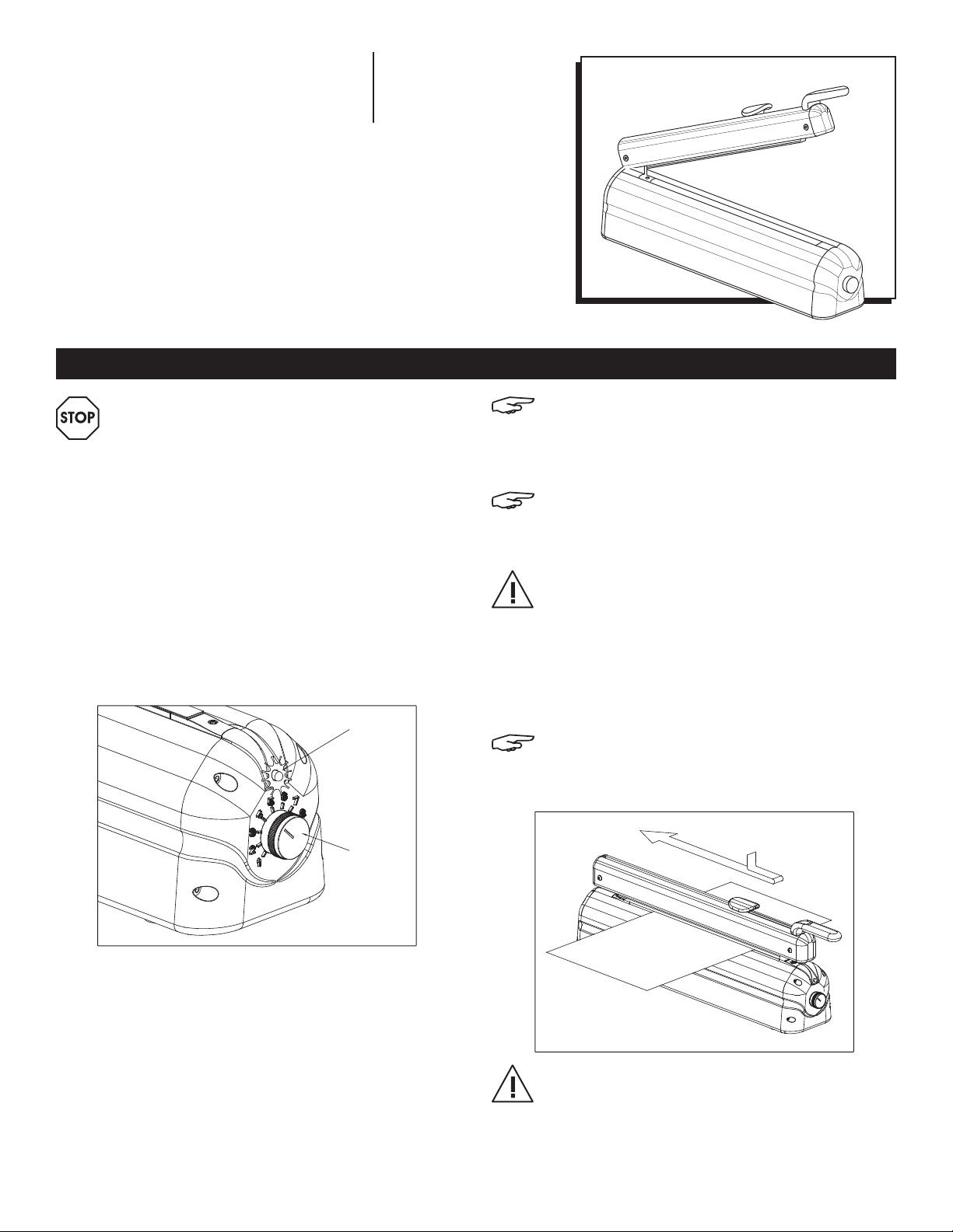
The machine is ready for operation after it is plugged into
an approved 115VAC electrical outlet and the yellow LED
illuminates. (See Figure 1A) Before operation, adjust the
sealing time to match the film’s type and width by conducting
a test sealing:
1. Set regulator button to lowest setting (#1 setting).
(See Figure 1B)
A
B
NOTE: The quality of the seal depends on the
thickness of the film and its composition. Test
sealing should always be conducted at a low
setting. If necessary, sealing time can be increased
in small steps.
NOTE: To achieve the best seal, keep the handle
down for a few seconds after the sealing operation
is complete. This allows the seal to cool down under
pressure and become permanent.
WARNING! Sealing at a higher temperature than
necessary may result in premature wear of parts
and excessive melting of packaging material.
USING THE CUTTING KNIFE
For safety reasons, the knife is secured in position by a spring.
To cut the film, press down on the knife and move it back
and forth.
NOTE: For best results, first press the knife head down
in the middle of the sealed film and slide it back
and forth. This helps prevent film breakage on the
sides. (See Figure 2)
Figure 1
2. Place film between sealing head and sealing electrode.
3. Close sealing head, hold down handle and wait for end
of sealing cycle. LED changes from yellow to red while
machine is sealing.
4. When sealing is complete, LED changes from red to
yellow.
5. Allow seal to cool down for 1-2 seconds and lift handle.
6. If bag is not fully sealed, increase sealing time by turning
regulator button to higher setting and repeat steps 2-5.
PAGE 1 OF 4 0715 IH-2065
Figure 2
WARNING! To prevent injury, never operate the knife
head when the sealing bar is open. Before using,
always ensure that the knife is intact and positioned
correctly.
Page 2
MAINTENANCE
CLEANING
The machine does not require special care. However, it is
advisable to remove any residue from the sealing head and
silicone rubber before it burns on. Use a damp, wet cloth to
clean. Do not use cleaning products that contain solvents.
REPLACING WORN PARTS
Only use Uline replacement parts.
REPLACING THE PTFE TAPE AND SEALING WIRE
To replace the PTFE tape and sealing wire:
1. Remove upper PTFE tape (See Figure 3A) and unscrew
fastening screws on side of sealing electrode.
(See Figure 3B)
2. Remove safety caps from sealing wire tensioning units.
(See Figure 3C)
3. Carefully pull sealing wire up and remove from machine.
(See Figure 3D)
4. Remove PTFE tape attached to machine. (See Figure 3E)
NOTE: When changing the PTFE tape, always ensure
the tape under the sealing wire is intact. While
changing the sealing wire, it is advisable to install
the protective cap backwards on the sealing wire
tensioning unit.
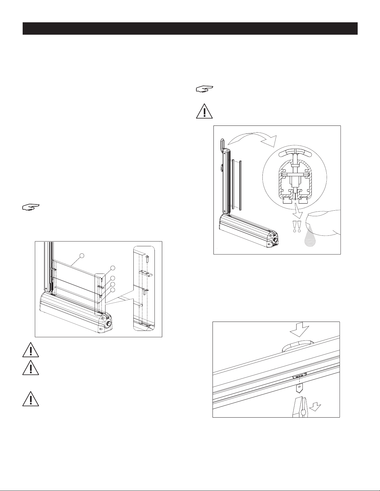
REPLACING THE SILICONE RUBBER
Pull out the damaged or burned silicone rubber from sealing
bar and clip in the new silicone rubber. (See Figure 4)
When installing the silicone rubber, observe the direction of
the profile.
NOTE: It is not necessary to pull the silicone rubber
through the profile. It can be clipped in easily.
WARNING! When changing the silicone rubber, use
caution around the sharp knife in the sealing bar’s
knife assembly. (See Figure 4)
Figure 4
A
B
C
D
E
REPLACING THE KNIFE
To replace a blunt, dull or broken knife:
1. Lift sealing bar and press down on head of knife assembly.
(See Figure 5A)
2. Pull knife out of its housing with pliers. (See Figure 5B)
3. Insert new knife.
Figure 3
Figure 5
A
WARNING! For safety, used or burned PTFE tape
should be replaced immediately.
WARNING! To prevent an electrical short, cut each
side of lower self adhesive PTFE tape 4 mm
(about 1⁄8") longer than the aluminum side panel of
the machine.
WARNING! Never apply tape to the surface of the
sealing wire. It must move freely under the upper
B
PTFE strap. (Only a portion of the upper strap is
treated with adhesive.)
PAGE 2 OF 4 0715 IH-2065
Page 3

MAINTENANCE CONTINUED
REPLACING THE KNIFE ASSEMBLY
To replace a worn or damaged knife assembly:
1. Remove front cap in front side of sealing bar as it opens.
(See Figure 6A)
2. Loosen screws that hold handle and remove.
(See Figure 6B)
3. Detach screws that fasten sealing head. (See Figure 7A)
Figure 6 Figure 7 Figure 8
4. Remove spreader from aluminum profiles. (See Figure 7B)
5. Pull out old knife assembly and replace. (See Figure 8A)
6. Reinstall sealing head by performing steps 1-5 in reverse
order.
NOTE: Always replace the front cap, the machine
will not operate without it.
B
A
A
B
A
TROUBLESHOOTING
A
OPERATING ISSUE RECOMMENDATIONS
LED lamp does not illuminate. Machine does not seal.
LED lamp illuminates yellow but does not change to
red when handle is closed. Machine does not seal.
LED lamp illuminates normally, but machine does
not seal.
Sealing is not acceptable.
Loose handle.
Ensure the machine is connected to an
electrical outlet.
Is the outlet “live?”
Check if the control panel is damaged.
Ensure that sufficient force is used to press
handle down. (Do not press the handle
sideways.)
Is the front cap on the handle? Is the magnet
inside it?
Check if the control panel is damaged.
Unplug from power immediately. Ensure sealing
wire, PTFE tapes and transformer are intact.
Change sealing time with regulator button.
(Sealing time increases proportionally with
thickness of film.)
After sealing, allow 1-2 sec. to cool. (Cooling
time increases proportionally with sealing time.)
Tighten hinge bolts.
Sealing wire heats up immediately when machine is
plugged in.
PAGE 3 OF 4 0715 IH-2065
Check if the control panel is damaged.
Immediately unplug from electrical power and
call Uline at 1-800-295-5510
Page 4

TECHNICAL INFORMATION
TYPE
H-2065 12.60" 11. 81" 11. 81" 20.99 x 3.95 x 6.89 7.9 l b s .
TYPE OF
TRANSFORMER
H-2065 110 /17,6 V 240 w 2,2 a 6 a
SEALING
LENGTH
PRIMARY/SECONDARY
NOMINAL VOLTAGE
MAX. FILM
WIDTH
CUTTING
LENGTH
NOMINAL
ELECTRIC POWER
MACHINE
DIMS
NOMINAL
CURRENT
NET
WEIGHT
USED FUSES
REFERENCE
4
3
2
1
7
8
5
6
13
12
#
DESCRIPTION
1 Main Electric Cable
2 Hinge Bolt
3 Sealing Bar
4 Knife Assembly
5 Handle
6 Front Cap (Magnetic)
7 Silicone Rubber
8 Sealing Unit (Sealing Wire With Upper And Lower Ptfe Tape)
9 Led (Lamp)
10 Regulator Button
11 Front Cover
12 Machine Frame
13 Back Cover
9
10
11
π
CHICAGO • ATLANTA • DALLAS • LOS ANGELES • MINNEAPOLIS • NYC/PHILA • SEATTLE • MEXICO • CANADA
1-800 -295 -5510
PAGE 4 OF 4 0715 IH-2065
uline.com
 Loading...