

Page 1
Para Español, vea páginas 6-10.
Pour le français, consulter les pages 11-15.
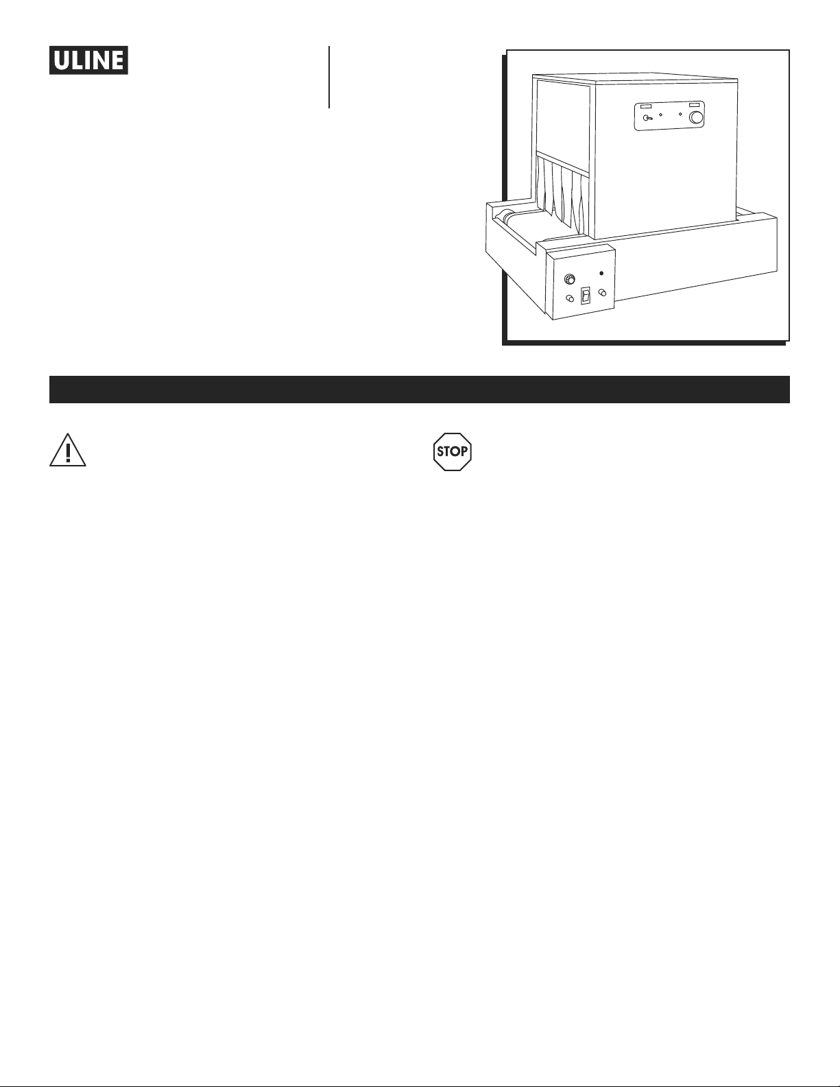
H-2034, H-2035
SHRINK TUNNEL
1-800-295 -5510
uline.com
SPECIFICATIONS
IMPORTANT! Read this manual thoroughly
and familiarize yourself with ALL controls and
operating features. Keep this manual for future
reference and maintenance.
Unpacking: Check the machine for damage.
If damage is found, return to Uline.
MACHINE SPECIFICATIONS
• Package Size Capabilities: Tunnel 16 x 8".
• Speed: Will vary with length of package.
• Power Supply: 220 volt, 10 amp mesh belt conveyor.
• Overall Dimensions: 32"L x 27"W x 28"H.
TUNNEL STANDARD FEATURES
• 2,100-Watt tunnel heating power.
• 360-degree air circulation.
MESH BELT CONVEYOR
• Teflon coated mesh belt.
WARNING! Damage to the machinery can
be caused by (but not limited to): electrical
overload, mechanical overload, incorrect
power source, lifting and/or moving the
equipment improperly, and misuse of
assemblies. Any damage from the above
constitutes misuse and/or abuse and we will not
be covered by the manufacturer's warranty.
This manual contains multiple precautionary
notes indicated with the word "CAUTION" and/
or "WARNING". Such notes are used to describe
functions that can cause bodily injury and/or
damage to the machine. Notes marked with
"WARNING" indicate a condition that can cause
harm to a person. Notes marked with "CAUTION"
indicate conditions which can cause damage
to the machine.
It is the employer's responsibility to ensure all
personnel associated with the operation of
this machine are adequately trained in the
operation, safety precautions and potential
hazards of this machinery.
• Speed controlled tunnel conveyor. 0-60 FPM.
WARRANTY
• Full 1-year warranty on parts.
0521 IH-2034PAGE 1 OF 15
Page 2
INSTRUCTIONS
GENERAL
1. H-2034 Shrink Tunnel consists of a tunnel and a
conveyor.
The conveyor is a teflon coated mesh belt.
The mesh belt allows the heated air to shrink the
bottom of the package from the tunnel.
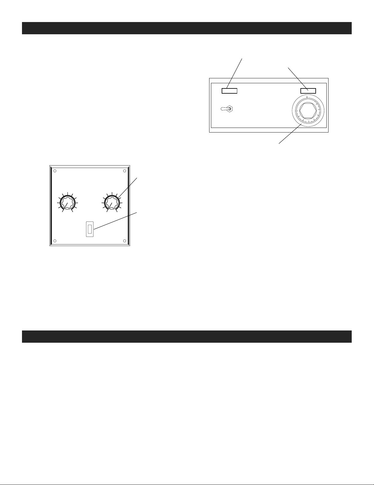
2. There are two control panels for the operation of
the machine. The lower panel controls the conveyor
and the upper panel controls the tunnel.
MACHINE STARTUP
1. Turn on the conveyor using the ON/OFF rocker switch.
The ON/OFF switch will light up. Set the conveyor
speed to "2" on the operator panel. (See Figure 1)
Figure 1
3
2
1
CONVEYOR
SPEED
5
4
6
POWER
MAIN
CONVEYOR
TEMP
5
6
4
7
8
9
3
2
1
RESET
OFF
7
8
9
820HB Only
ON/OFF Switch
Circuit Breaker
Figure 2
Power Light
Heat Indicator Light
OFF
550
500
450
200
ON/OFF
400
250
350
300
Thermostat
4. Set the tunnel temperature to a setting of 325º F
on the tunnel’s operator panel. It will take 20-30
minutes to reach temperature. The heat indicator
light will go off when it has reached temperature.
(See Figure 2)
5. After the initial package has been run through the heat
shrink tunnel, the following adjustments may be made:
a. Increase or decrease the thermostat setting.
b. Increase or decrease the conveyor speed.
2. If the power light is not on, plug in the tunnel.
3. Turn on the tunnel using the ON/OFF switch.
MAINTENANCE
The machine should be inspected on a timely basis to
ensure all is functioning well and in good working order.
There is not much required to keep the machine running
trouble free. The most important area is the seal head.
The following are recommendations for preventative
maintenance on the machine to keep it performing well
over an extended period.
c. Increase or decrease the temperature if
available.
6. Due to the various types of shrinkable films, room
temperatures and voltages, you may have to
experiment with various temperatures and conveyor
speeds, to get the desired shrink. Your film supplier
is familiar with this type of equipment and will be
helpful in determining the best settings for the film
you are using.
MAINTENANCE TIPS
1. Inspect the conveyor belts for wear and
misalignment. If the belts are not tracking properly,
adjust the idler rollers to realign the belts. Replace
worn belts as needed.
2. Lubricate all chain drives every 160 hours of
operation with a bearing grease or chain lubricant.
3. To clean the machine, wipe down the conveyor
belts and other flat surfaces to remove any dirt.
Do not use any type of belt dressing on the
conveyor belts.
0521 IH-2034PAGE 2 OF 15
Page 3
MACHINE COMPONENTS
MAIN FRAME ASSEMBLY
1. The main frame assembly of this machine consists of
the rails, conveyor drive motor, and the operator panel.
TUNNEL CONVEYOR ASSEMBLY MESH BELT
1. T
his assembly consists of the tunnel conveyor belt
as
sembly including the DC gear motor. The belt is
heated by a 500W heat element mounted under
the conveyor pan. The heated belt provides positive
shrink on the bottom of the package. The assembly
also includes belt guides and tracking screws.
TUNNEL CONVEYOR ASSEMBLY HEATED BELT
1. This assembly consists of the heated belt including
the DC gear motor. The belt is heated by a 500W
heating element mounted under the conveyor
pan. The heated belt provides positive shrink on the
bottom of the package. The assembly also includes
belt guides and tracking screws.
TUNNEL ASSEMBLY
1. The tunnel assembly set on the tunnel conveyor
uses heated recirculated air to shrink the film onto
the package. The assembly has its own power cord
and requires a dedicated 20Amp circuit. The blower
motor runs in a counterclockwise direction when
looking at the non-shaft end. (See Figure 2)
ELECTRICAL PANEL ASSEMBLY
1. This assembly is located under the drive roller. Only
a qualified technician should access this assembly.
WARNING! Do not tamper with electrical wiring
unless licensed or trained to do so. Disconnect
main power to the machine before attempting
any electrical service.
2. Electrical schematics can be found in the original
manual.
OPERATOR PANEL ASSEMBLY
1. The operator assembly panel consists of the ON/
OFF switch, adjustment for the conveyor speed and
conveyor temperature if available.
2. The ON/OFF switch also acts as a circuit breaker for
the conveyor system. (See Figure 1)
3. The Conveyor Speed is controlled using a DC Drive
Board (203-61) mounted in the Operator Panel. The
speed can vary from 0 feet per minute to 60 feet
per minute.
4. The Conveyor Temperature is controlled using a
variable voltage supply.
CONSOLE LEG KIT (Optional, see below)
1. ULINE item H-2035.
INSTALLATION AND SETUP
IMPORTANT! Prior to machine set up and
installation the general warnings should be
read and fully understood by all personnel
associated with this machinery.
SET-UP INSTRUCTIONS
1. Remove the tunnel from the crate or box.
Inspect for damage.
2. If available, attach the console stand to the tunnel
conveyor rails. See the enclosed instructions for the
stand. Level the machine using the levelers.
3. Place the tunnel on the conveyor with the operator
panels toward the front.
4. Remove any ties used for shipping.
5. Connect machine to power source. Power supply
for the tunnel should be 220 Volt, 10 Amp grounded
power supply. (Have an electrician install a plug on
the power cord, if you are plugging the tunnel into
an electrical outlet.)
CAUTION! Machine should be grounded in
accordance with local electrical codes.
6. Turn on the power to the conveyor using the ON/OFF
switch. Turn on the tunnel using its ON/OFF switch.
7. Ensure the tunnel conveyor is slowly running.
Ensure the tunnel blower is working. Turn the tunnel
temperature to 325º F. When the tunnel has reached
temperature, check the tracking of the tunnel
conveyor’s belt.
8. Test run a few products through the machine to fine
tune the settings in order to achieve as tight a bag
around the product as practical. This will aid in the
shrink process.
9. When finished, turn the tunnel and conveyor
temperatures off. Wait 15-20 minutes and turn off the
tunnel and conveyor.
0521 IH-2034PAGE 3 OF 15
Page 4
OPTIONAL LEG KIT INSTALLATION AND SETUP
CAUTION! Assembling the leg kit to the
conveyor can be dangerous. Two people or
a mechanical lift device must be used to
position the conveyor above the leg kit until
they are attached.
SET-UP INSTRUCTIONS
1. Remove the leg kit from the crate. Inspect for
damage.
2. To adjust leg length, remove shipping bolts from legs
(1 bolt per leg). Adjust leg length by measuring the
desired height and subtracting 12" to account for
the conveyor and caster height.
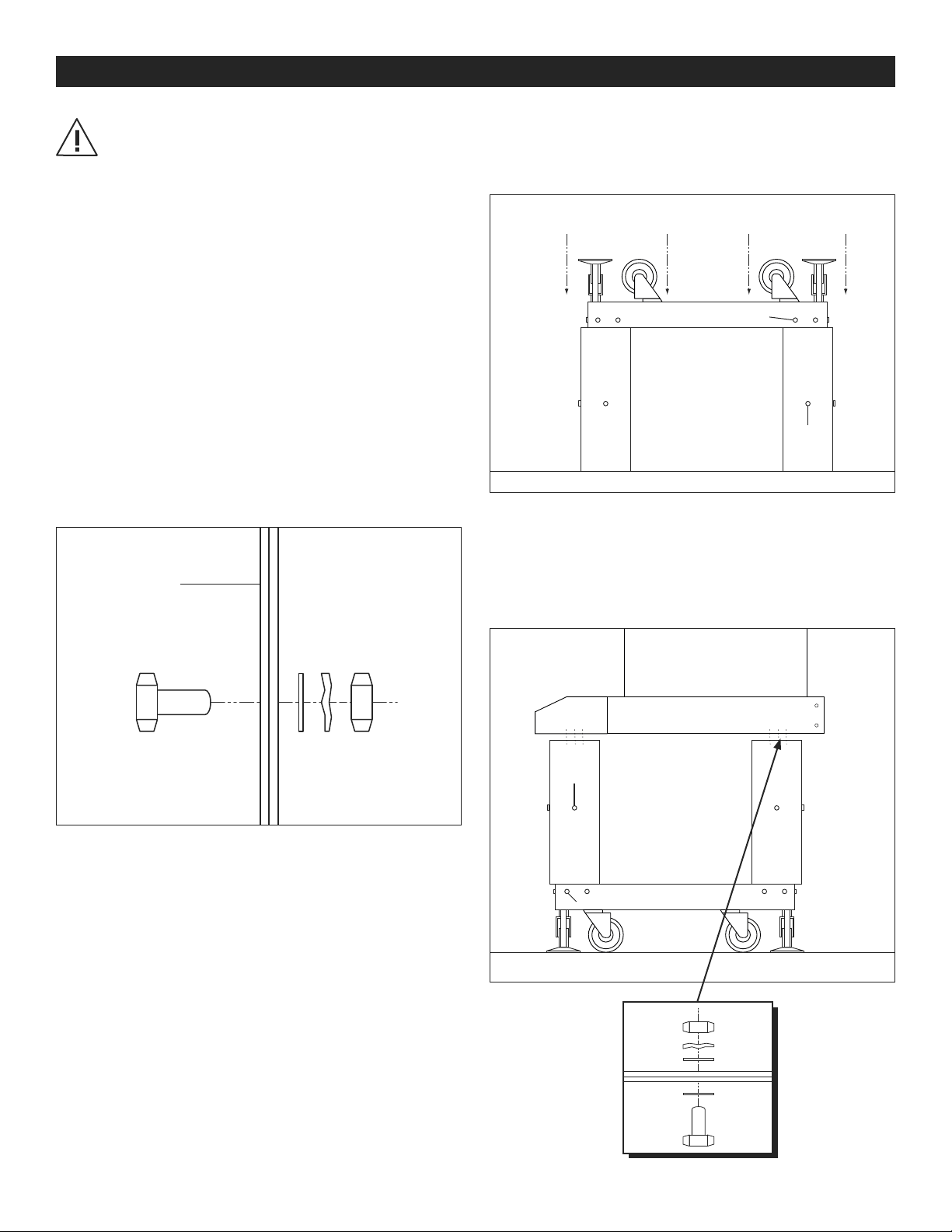
3. Place legs upside down on floor. Position shelf on
legs. Insert socket screws through shelf and each leg
from outside (7 places per leg). Tighten screws with
flat washers, lock washers and nuts. Use a socket
wrench. (See Figure 3)
Figure 3
Outside
4. Screw feet into threaded holes provided on bottom
of the shelf. Insert casters into nylon insert next to
feet. (See Figure 4)
Upside Down View
Socket Screw
Figure 4
Hex
Bolt
5. Turn the leg kit right side up. Place conveyor on top
of the leg kit assembly. Insert hex bolts through the
conveyor and leg kit (2 bolts per corner). Tighten
bolts
with flat washers, lock washers and nuts.
(See Figure 5)
Hex
Bolt
Socket Screw
Figure 5
0521 IH-2034PAGE 4 OF 15
Page 5

TROUBLESHOOTING
1
0
uline.com
The following guidelines are intended to ease the
solution of potential problems that may be encountered
during the everyday operations of the machine.
The cause/solution statements are generally arranged
in order of most probable, easiest solution first on up to
more involved, difficult solutions. If all possible solutions
have been tried, the distributor or factory should be
consulted.
OPERATING ISSUE RECOMMENDATIONS
Conveyor does not power on. Check incoming power. The ON/OFF switch should be lit.
Check power supply line.
Check On/Off switch on the operator panel.
Conveyor powers on but
conveyor does not run.
Conveyor powers on
belt does not heat up.
Check the position of the Conveyor Speed Pot.
Check the voltage to the DC Drive board. The incoming voltage should be equal to the line voltage.
Check the voltage from DC Drive Board. The voltage is DC and will vary with the speed pot setting. If
there isn’t output voltage, replace the board, 203-62.
Check the wiring to the motor. Replace the gear motor.
Check the position of the Conveyor Temp Pot.
Check the voltage to the Voltage Controller. The incoming voltage will vary with the speed pot
setting.
Check heat element for continuity. The 220V element has a resistance of 97 ohms. (Note that the
resistance given is a nominal value.)
Tunnel powers on but does not
heat.
Tunnel conveyor not tracking. Check tension roller on assembly (belt will track to tighter side). Be careful not to over tighten.
Check incoming power. 20-amp service is required.
With power removed check if the thermostat is turning on by checking continuity across wires #1
and #3.
Check the resistance of the heating element. The 220V element has a resistance of 23 ohms.
the resistance value given is a nominal value.)
E
nsure the voltage matches the element voltage.
Check the operation of the blower motor.
Check for air leaks around the blower housing and manifolds.
Check for worn belt.
Check the condition of the belt guides. The belt guides should just touch both sides of the belt.
(Note that
-800-295-551
0521 IH-2034PAGE 5 OF 15
Page 6

H-2034, H-2035
TÚNEL TERMOENCOGIBLE
800-295 -5510
uline.mx
ESPECIFICACIONES
¡IMPORTANTE! Lea detenidamente este manual
y familiarícese con TODOS los controles y
características de funcionamiento. Conserve este
manual para referencias futuras y mantenimiento.
Desempaque: Inspeccione la máquina en busca
de daños. Si se encuentra algún daño, regrésela a
Uline.
ESPECIFICACIONES DE LA MÁQUINA
• Capacidades tamaño del paquete: Túnel 40.6 x 20.3 cm
(16 x 8").
• Velocidad: Varía de acuerdo con la longitud
del paquete.
• Suministro de electricidad: Banda transportadora de
malla a 10 amperes, 220 voltios.
• Dimensiones generales: 81.3 cm Largo x 68.6 cm Ancho x
71.1 cm Alto (32" Largo x 27" Ancho x 18" Alto).
CARACTERÍSTICAS ESTÁNDARES DEL TÚNEL
• 2100 vatios de potencia de calefacción del túnel.
• Circulación de aire de 360 grados.
BANDA TRANSPORTADORA DE CORREA DE MALLA
¡ADVERTENCIA! Los daños a la máquina pueden ser
causados por (pero no limitados a): sobrecarga
eléctrica, sobrecarga mecánica, fuente de
alimentación incorrecta, levantar y/o mover el
equipo de manera incorrecta y el uso indebido de
los ensambles. Cualquier daño de los mencionados
anteriormente constituye uso indebido y/o abuso y
no será cubierto por la garantía del fabricante.
Este manual contiene varias notas de precaución
indicadas con la palabra "PRECAUCIÓN" y/o
"ADVERTENCIA". Dichas notas se utilizan para
describir las funciones que pueden causar
lesiones corporales y/o daños a la máquina. Las
notas marcadas con "ADVERTENCIA" indican una
condición que puede causar daño a una persona.
Las notas marcadas con "PRECAUCIÓN" indican
condiciones que pueden causar daños a la
máquina.
Es la responsabilidad del empleador asegurarse de
que todo el personal asociado con la operación
de esta máquina esté debidamente capacitado
en la operación, precauciones de seguridad y los
peligros potenciales de esta maquinaria.
• Correa de malla recubierta de teflón.
• Banda transportadora del túnel con control de velocidad
0-60 FPM.
GARANTÍA
• Garantía total de 1 año en piezas.
0521 IH-2034PAGE 6 OF 15
Page 7

INSTRUCCIONES
Temperatura
de la Banda
Transportada
Interruptor del
GENERALIDADES
1. El túnel termoencogible H-2034 consiste de un túnel y
una banda transportadora. La banda transportadora es
una correa de malla recubierta de teflón. La correa de
malla permite que el aire caliente reduzca el tamaño de
la parte inferior del paquete desde el túnel.
2. Hay dos paneles de control para la operación de
la máquina. El panel inferior controla la banda
transportadora y el panel superior controla el túnel.
ARRANQUE LA MÁQUINA
1. Encienda la banda transportadora con el interruptor
basculante ON/OFF. El interruptor ON/OFF se iluminará.
Ajuste la velocidad de la banda transportadora en "2" en
el panel del operador. (Vea Diagrama 1)
Diagrama 1
Velocidad
de la Banda
Transportada
3
2
1
CONVEYOR
SPEED
5
4
CONVEYOR
TEMP
6
7
8
9
5
6
4
3
2
1
7
8
9
820HB
Solamente
Diagrama 2
Luz de Encendido
Luz Indicadora de Calor
OFF
550
500
450
200
ON/OFF
400
250
350
300
Encendido/
Apagado
Termostato
4. Ajuste la temperatura del túnel a un ajuste de 163ºC
(325ºF) en el panel del operador del túnel. Le tomará
aproximadamente de 20 a 30 minutos alcanzar la
temperatura. La luz indicadora de calor se apagará
cuando se haya alcanzado la temperatura. (Vea
Diagrama 2)
5. Después de que el paquete inicial haya pasado a través
del túnel termoencogible, se pueden hacer los siguientes
ajustes:
RESET
MAIN
POWER
OFF
Circuito de
Encendido/
Apagado
2. Si la luz de encendido está apagada, conecte el túnel.
3. Encienda el túnel con el interruptor ON/OFF.
MANTENIMIENTO
La máquina debe ser inspeccionada de forma oportuna
para garantizar que todo esté en buen estado y funcionando
bien. No se necesita mucho para mantener la máquina
funcionando sin problemas. El área más importante es el
cabezal de sellado. Las siguientes recomendaciones son
para el mantenimiento preventivo de la máquina para que
continúe funcionando bien durante un período prolongado.
a. Aumentar o disminuir el ajuste del termostato.
b. Aumentar o disminuir la velocidad de la banda
transportadora.
c. Aumentar o disminuir la temperatura si está
disponible.
6. Debido a los diversos tipos de películas termoencogibles,
las temperaturas ambiente y voltajes, es posible que
tenga que experimentar con diferentes temperaturas y
velocidades de la banda transportadora para obtener el
encogimiento deseado. Su proveedor de películas está
familiarizado con este tipo de equipos y le ayudará a
determinar la mejor configuración para la película que
está utilizando.
CONSEJOS DE MANTENIMIENTO
1. Inspeccione las correas transportadoras por si presentan
desgaste y desalineación. Si las correas no están
rodando correctamente, ajuste los rodillos locos para
realinearlas. Reemplace las correas desgastadas según
sea necesario.
2. Lubrique todas las transmisiones por correa cada
160 horas de funcionamiento con una grasa para
rodamientos o lubricante de cadenas.
3. Use un paño sobre las correas transportadoras y otras
superficies planas para limpiar la máquina y eliminar
la suciedad. No use ningún tipo de acondicionador de
correas en las correas de la banda transportadora.
0521 IH-2034PAGE 7 OF 15
Page 8

COMPONENTES DE LA MÁQUINA
ENSAMBLE DEL ARMAZÓN PRINCIPAL
1. El ensamble del armazón principal de esta máquina
consiste de los rieles, motor de tracción de la banda
transportadora y el panel del operador.
ENSAMBLE DE LA CORREA DE MALLA DEL TUNEL
DE LA BANDA TRANSPORTADORA
1. Este ensamble consiste en el ensamble de la correa
del tunel, incluyendo el motor de engranaje CC. La
correa se calienta mediante una resistencia a 500 W
montada debajo de la bandeja transportadora. La correa
calentada proporciona un encogimiento positivo en la
parte inferior del paquete. El ensamble incluye también
las guías de la correa y tornillos de seguimiento.
ENSAMBLE DE LA CORREA CALIENTE DEL TUNEL
DE LA BANDA TRANSPORTADORA
1. Este ensamble consiste de la banda calentada incluyendo
el motor de engranaje CC. La correa se calienta mediante
una resistencia a 500 W montada debajo de la bandeja
transportadora. La correa calentada proporciona un
encogimiento positivo en la parte inferior del paquete. El
ensamble incluye también las guías de la correa y tornillos
de seguimiento.
ENSAMBLE DEL TÚNEL
1. El ensamble del túnel situado en la banda
transportadora del túnel usa aire caliente recirculado
para encoger la película sobre el paquete. El ensamble
tiene su propio cable de alimentación y requiere un
circuito dedicado a 20 A. El motor del soplador funciona
en el sentido contrario de las agujas del reloj cuando se
mira en el extremo que no es del eje. (Ver Diagrama 2)
ENSAMBLE DEL PANEL DE ELECTRICIDAD
1. Este ensamble se encuentra ubicado bajo el el rodillo de
tracción. Sólo un técnico calificado debe tener acceso a este
ensamble.
¡ADVERTENCIA! No manipule las conexiones eléctricas
de manera indebida a menos que tenga licencia
o esté capacitado para hacerlo. Desconecte la
alimentación principal de la máquina antes de
realizar cualquier servicio eléctrico.
2. Los esquemas eléctricos se pueden encontrar en el
manual original.
ENSAMBLE DEL PANEL DEL OPERADOR
1. El panel de ensamble del operador consiste en el
interruptor ON/OFF, el ajuste de la velocidad de la
banda transportadora y de la temperatura de la banda
transportadora si está disponible.
2. El interruptor de ENCENDIDO Y APAGADO (ON/OFF)
también actúa como un interruptor para el sistema de la
banda transportadora. (Ver Diagrama 1)
3. La velocidad de la banda transportadora se controla
utilizando un tablero de control CC (203-61) montada
en el panel del operador. La velocidad puede variar de
0 metro por minuto a 18.3 metros por minuto (0 pies por
minuto a 60 pies por minuto).
4. La temperatura de la banda transportadora se controla
mediante el uso de un suministro de voltaje variable.
KIT DE PATAS PARA CONSOLA (Opcional, vea abajo)
1. ULINE artículo H-2035.
INSTALACIÓN Y CONFIGURACIÓN
¡IMPORTANTE! Antes de configurar e instalar la
máquina, se deben leer las advertencias generales
y ser entendidas a cabalidad por parte de todo el
personal asociado con esta maquinaria.
INSTRUCCIONES DE CONFIGURACIÓN
1. Retire el túnel del embalaje o caja.
Inspeccione si hay daños.
2. Si está disponible, conecte el soporte de la consola a
los rieles de la banda transportadora del túnel. Consulte
las instrucciones adjuntas del soporte. Nivele la máquina
con los niveladores.
3. Coloque el túnel en la banda transportadora con los
paneles de operador hacia la parte frontal.
4. Quite las ataduras utilizadas para el envío.
5. Conecte la máquina a la fuente de alimentación. La
fuente de alimentación para el túnel debe ser de 220
voltios, 10 A y estar aterrizada. (Pídale a un electricista
que instale el enchufe en el cable de alimentación, si
va a conectar el tún el a un a toma el éctrica).
¡PRECAUCIÓN! La máquina debe estar conectada a
tierra de acuerdo con los códigos eléctricos locales.
6. Encienda la alimentación de la banda transportadora
con el interruptor ON/OFF. Encienda el túnel con el
interruptor ON/OFF.
7. Asegúrese de que la banda transportadora del túnel esté
funcionando lentamente. Asegúrese de que el soplador
del túnel esté funcionando. Ponga la temperatura del
túnel a 162.8ºC (325ºF). Cuando el túnel haya alcanzado
la temperatura, compruebe el movimiento de la correa
de la banda transportadora del túnel.
8. Haga una prueba de funcionamiento con algunos
productos a través de la máquina para afinar los ajustes a
fin de lograr apretar la bolsa alrededor del producto según
sea práctico. Esto ayudará en el proceso de encogimiento.
9. Cuando termine, apague las temperaturas del túnel y de
la banda transportadora. Espere de 15 a 20 minutos y
apague el túnel y la banda transportadora.
0521 IH-2034PAGE 8 OF 15
Page 9

INSTALACIÓN Y CONFIGURACIÓN DEL KIT DE PATAS OPCIONAL
¡PRECAUCIÓN! Montar el kit de patas a la banda
transportadora puede ser peligroso. Deben trabajar
dos personas o usar un dispositivo mecánico de
elevación para ubicar la banda transportadora
sobre el kit de patas hasta que éstas se hayan fijado.
INSTRUCCIONES DE CONFIGURACIÓN
1. Retire el kit de patas del embalaje. Inspeccione si hay
daños.
2. Para ajustar la longitud de la pata, retire los pernos de
envío de las patas (1 perno por pata). Ajuste la longitud
de la pata midiendo el alto deseado y restándole
30.5 cm (12") para tomar en cuenta la altura de la banda
transportadora y la rueda.
3. Coloque las patas boca abajo en el piso. Posicione
la repisa en las patas. Insterte los tornillos de cabeza
hueca a través de la repisa y cada pata desde afuera
(7 lugares por pata). Apriete los tornillos con arandelas
planas, arandelas de seguridad y tuercas. Use una llave
de dado. (Vea Diagrama 3)
Diagrama 3
Exterior
4. Atornille las patas en los orificios roscados incluidos en la
parte inferior de la repisa. Inserte las ruedas en el inserto
de nylon junto a las patas. (Vea Diagrama 4)
Vista desde abajo
Tornillo de cabeza hueca
Perno
Hexagonal
5. Gire el kit de patas con el lado derecho hacia arriba.
Coloque la banda transportadora encima del ensamble
del kit de patas. Inserte los pernos hexagonales a través
de la banda transportadora y el kit de patas (2 pernos
por esquina). Apriete los pernos con arandelas planas,
arandelas de seguridad y tuercas. (Vea Diagrama 5)
Diagrama 4
Diagrama 5
Perno
Hexagonal
Tornillo de cabeza hueca
0521 IH-2034PAGE 9 OF 15
Page 10

SOLUCIÓN DE PROBLEMAS
8
0
uline.mx
Las siguientes directrices están destinadas a facilitar la
solución de los problemas potenciales que se pueden
presentar durante el funcionamiento cotidiano de la
máquina.
PROBLEMA DE
OPERACIÓN
La banda transportadora no
enciende.
La banda transportadora
enciende, pero la banda
transportadora no funciona.
La banda transportadora
enciende, la correa no se
calienta.
Verifique entrada de electricidad. El interruptor ON/OFF debe estar iluminado.
Verifique la línea de suministro de electricidad.
Verifique el interruptor ON/OFF en el panel del operador.
Verifique la posición del potenciómetro de velocidad de la banda transportadora.
Verifique el voltaje en el tablero de control CC. El voltaje de entrada debe ser igual al voltaje de línea.
Verifique el voltaje saliente del tablero de control CC. El voltaje es de CC y pueden variar con el
ajuste del potenciómetro de velocidad. Si no hay voltaje de salida, reemplace el tablero, 203-62.
Verifique el cableado hacia el motor. Reemplace el motor del mecanismo.
Verifique la posición del potenciómetro de temperatura de la banda transportadora.
Verifique el voltaje al controlador de voltaje. El voltaje de entrada puede variar con el ajuste del
potenciómetro de velocidad.
Verifique la continuidad de la resistencia. El elemento de 220 V tiene una resistencia de 97 ohmios.
(Tenga en cuenta que la resistencia dada es un valor nominal.)
Las declaraciones de causas / soluciones generalmente son
organizadas por orden; comenzando con la solución la más
probable y fácil primero y terminando con las soluciones más
complicadas y difíciles. Si ha intentado todas las soluciones
posibles, debe consultar al distribuidor o la fábrica.
RECOMENDACIONES
El túnel enciende, pero no se
calienta.
La banda transportadora del
túnel no se mueve.
Verifique entrada de electricidad. Se requiere un servicio de 20 A.
Con la electricidad desconectada, verifique si el termostato se enciende al verificar la continuidad a
través de los cables # 1 y # 3.
Verifique la resistencia. El elemento de 220 V tiene una resistencia de 23 ohmios. (Tenga en cuenta
que la resistencia dada es un valor nominal.)
Asegúrese de que el voltaje coincida con el voltaje del elemento.
Verifique el funcionamiento del motor del soplador.
Verifique que no haya fugas de aire alrededor de la carcasa del soplador y los colectores.
Verifique el rodillo tensor en el ensamble (la correa se moverá hacia el lado más apretado). Tenga
cuidado de no apretar demasiado.
Verifique si la correa está desgastada.
Verifique el estado de las guías de la correa. Las guías de las correas apenas deben tocar ambos
lados de la correa.
00-295-551
0521 IH-2034PAGE 10 OF 15
Page 11

H-2034, H-2035
TUNNEL DE RETRACTION
1-800-295 -5510
uline.com
SPÉCIFICATIONS
IMPORTANT! Veuillez lire attentivement ce manuel
et apprendre TOUTES les commandes et fonctions.
Conservez ce manuel pour une référence et
entretien ultérieur.
Déballage : Vérifiez l'état de l'appareil.
En cas de dommage, veuillez le retourner à Uline.
SPÉCIFICATIONS DE L'APPAREIL
• Dimensions de colis acceptables: Tunnel 40,6 x 20,3 cm
(16 x8po).
• Vitesse : Varie selon la longueur du colis.
• Alimentation électrique: Convoyeur à courroie maillée,
220V, 10ampères.
• Dimensionshors-tout: 81,3cm long. x 68,6cm larg. x
71,1cm haut. (32po long. x27po larg. x28pohaut.).
CARACTÉRISTIQUES STANDARDS DU TUNNEL
• Puissance de chauffage du tunnel, 2100Watts.
• Circulation d'air sur 360 degrés.
CONVOYEUR À COURROIE MAILLÉE
• Courroie maillée revêtue de Teflon.
ARRÊT
AVERTISSEMENT! La machinerie peut être
endommagée par, mais non de façon limitative:
une surcharge électrique, une surcharge
mécanique, une source d'alimentation
inappropriée, le soulèvement et/ou déplacement
inapproprié de l'équipement et l'utilisation
inappropriée des ensembles. Tout dommage
venant des éléments décrits ci-dessus sont
conséquences d’une mauvaise utilisation et/ou de
l’abus et ne sera pas couvert par la garantie du
fabricant.
Ce manuel contient de nombreuses remarques
de mise en garde identifiées par les expressions
«MISE EN GARDE» et/ou «AVERTISSEMENT» Les
dites remarques servent à décrire des fonctions qui
peuvent causer des blessures corporelles et/ou des
dommages à l'appareil. Les «AVERTISSEMENTS»
identifient un état qui peut provoquer des blessures
corporelles. Les «MISE EN GARDE» identifient des
états qui peuvent provoquer des dommages à
l'appareil.
L'employeur est responsable d'assurer que tout le
personnel associé à l'utilisation de cet appareil
est correctement formé pour l'utilisation de cet
appareil, ainsi que sur les mesures de sécurité et les
dangers potentiels associés à cet appareil.
• Convoyeur de tunnel à vitesse contrôlée. 0-60pi/min.
GARANTIE
• 1 an complet sur les pièces.
0521 IH-2034PAGE 11 OF 15
Page 12

INSTRUCTIONS
GÉNÉRALITÉS
1. Le tunnel de rétraction H-2034 est composé d'un tunnel
et d'un convoyeur.
Le convoyeur est une courroie maillée
revêtue de Teflon. La courroie maillée permet à de l'air
réchauffé de rétracter le dessous du colis dans le tunnel.
2. L'appareil est contrôlé par deux panneaux de
commande. Le panneau inférieur commande le
convoyeur et le panneau supérieur commande le tunnel.
MISE EN MARCHE DE L'APPAREIL
1. Démarrez le convoyeur à l'aide de l'interrupteur ON/OFF
(marche/arrêt). L'interrupteur ON/OFF s'illuminera. Réglez la
vitesse du convoyeur à "2" sur le panneau de commande
du convoyeur. (Voir Figure1)
Figure 1
3
2
1
CONVEYOR
SPEED
5
4
6
POWER
MAIN
CONVEYOR
TEMP
5
6
4
RESET
3
2
1
OFF
7
8
9
7
8
9
820HB
Seulement
Disjoncteur de
l'interrupteur
Figure 2
Voyant d'alimentation
Voyant de chaleur
OFF
550
500
450
200
ON/OFF
400
250
350
300
Thermostat
4. Réglez la température du tunnel à 163 °C (325 ºF)
sur le panneau de commande du tunnel. Il faudra
20-30 minutes avant que la machine n'atteigne cette
température. L'indicateur de chaleur s'éteindra quand
l'appareil aura atteint la température. (Voir Figure2)
5. Suivant le passage du premier colis dans le tunnel
d'emballage sous film rétractable, vous pouvez effectuer
les réglages suivants:
a. Hausser ou abaisser le réglage du thermostat.
b. Accélérer ou ralentir la vitesse du convoyeur.
c. Hausser ou abaisser la température, si disponible.
2. Si le voyant d'alimentation demeure éteint, branchez
le tunnel.
3. Démarrez le convoyeur à l'aide de l'interrupteur ON/OFF.
ENTRETIEN
L'appareil doit être inspecté régulièrement afin d'assurer
que tout est en bon état et fonctionne correctement. Il suffit
de peu pour assurer le fonctionnement sans problème de
l'appareil. La zone la plus importante est la tête de scellage.
Nous vous présentons ci-dessous des recommandations
d'entretien préventif à exécuter afin d'assurer le rendement
efficace de l'appareil pendant une longue période de temps.
6. Dû aux nombreux types de pellicule thermorétractable,
aux différentes températures ambiantes et aux différentes
intensités électriques, il se peut que vous ayez à
expérimenter avec divers réglages de température et
de vitesse de convoyeur afin d'obtenir la rétractation
voulue. Votre fournisseur de pellicule connaît ce type
d'équipement et pourra vous aider à identifier les bons
réglages pour la pellicule que vous utilisez.
CONSEILS D'ENTRETIEN
1. Inspectez les courroies de convoyeur pour la présence
d'usure et de désalignement. Si les courroies sont
désalignées, alignez-les en réglant les galets-guides.
Remplacez les courroies usées au besoin.
2. Graissez toutes les unités de chaîne avec la graisse à
roulements ou de la graisse à chaîne après toutes les 160
heures d'utilisation.
3. Pour nettoyer l'appareil, essuyez les courroies de
convoyeur et autres surfaces planes afin d'éliminer toute
saleté. N'employez pas de graisse pour courroies sur les
courroies de convoyeur.
0521 IH-2034PAGE 12 OF 15
Page 13

COMPOSANTS DE L'APPAREIL
ENSEMBLE DE CADRE PRINCIPAL
1. L'ensemble de cadre principal de cet appareil se compose
des rails, du moteur d'entraînement du convoyeur et du
panneau de commande.
ENSEMBLE DE COURROIE MAILLÉE DE
CONVOYEUR DE TUNNEL
1. C
et ensemble se compose de la courroie de
convoyeur de tunnel,
CC. La courroie est chauffée par un élément chauffant
de 500W installé sous le bac du convoyeur. La courroie
chauffée rétracte la pellicule sur le dessous du colis.
L'ensemble comprend aussi des guides de courroie et
des vis d alignement.
y compris le moteur à engrenages
ENSEMBLE DE COURROIE CHAUFFÉE DE
CONVOYEUR DE TUNNEL
1. Cet ensemble se compose de la courroie chauffée, y
compris le moteur à engrenages CC. La courroie est
chauffée par un élément chauffant de 500W installé sous
le bac du convoyeur. La courroie chauffée rétracte la
pellicule sur le dessous du colis. L'ensemble comprend
aussi des guides de courroie et des vis d'alignement.
ENSEMBLE DE TUNNEL
1. L'ensemble de tunnel installé sur le convoyeur de tunnel
emploie de l'air réchauffé recyclé pour rétracter la
pellicule sur le colis. L'ensemble possède son propre
cordon d'alimentation et exige un circuit spécialisé de
20ampères. Le moteur de soufflante tourne dans le
sens antihoraire lorsque vu de l'extrémité sans arbre.
(Voir Figure2)
ENSEMBLE DE PANNEAU ÉLECTRIQUE
1. Cet ensemble se situe sous le rouleau d'entraînement.
Seul un technicien qualifié devrait être autorisé à
accéder à cet ensemble.
AVERTISSEMENT! N'altérez pas le câblage
ARRÊT
électrique à moins d'y être officiellement
autorisé ou formé à cette fin. Débranchez la
source d'alimentation principale de l'appareil
avant d'entamer tout entretien électrique.
2. Les schémas électriques figurent dans le manuel original.
ENSEMBLE DE PANNEAU DE COMMANDE
1. L'ensemble de panneau de commande se compose
de l'interrupteur ON/OFF, de la commande de vitesse
du convoyeur et de la température du convoyeur si
disponible.
2. L'interrupteur ON/OFF sert aussi de disjoncteur pour le
système de convoyeur. (Voir Figure1)
3. La vitesse du convoyeur est commandée au moyen d'un
panneau d'entraînement CC (203-61) installé dans le
panneau de commande. La vitesse peut varier de 0 à 60
pieds par minute.
4. La température du convoyeur est commandée au moyen
d'une tension d'aliment ation variable.
TROUSSE DE PATTES DE CONSOLE
(Optionnel, voir ci-dessous)
1. Article ULINE H-2035.
INSTALLATION ET ASSEMBLAGE
IMPORTANT! Avant d'assembler et d'installer
l'appareil, tout le personnel associé à cet appareil
doit lire et comprendre les avertissements généraux.
INSTRUCTIONS D'ASSEMBLAGE
1. Retirez le tunnel de la caisse ou la boîte.
Inspectez pour la présence de dommages.
2. Si disponible, fixez le stand de console aux rails du
convoyeur de tunnel. Voir les instructions comprises pour
le stand. Nivelez l'appareil à l'aide des patins réglables.
3. Positionnez le tunnel sur le convoyeur avec les panneaux
de commande orientés vers l'avant.
4. Retirez toutes les attaches employées pour l'expédition.
5. Branchez l'appareil sur une source d'alimentation. La
source d'alimentation pour le tunnel doit être une source
d'alimentation 220V, 10ampères, mise à la terre. (Si vous
branchez le tunnel dans une prise électrique murale,
faites installer une fiche sur le cordon d'alimentation par
un électricien.)
MISE EN GARDE! L'appareil doit être mis à la terre en
conformité avec les codes électriques locaux.
6. Mettez le convoyeur sous tension à l'aide de l'interrupteur
à bascule ON/OFF (marche/arrêt). Démarrez le convoyeur
à l'aide de son interrupteur ON/OFF.
7. Assurez-vous que le convoyewur fonctionne lentement.
Assurez-vous que la soufflante fonctionne. Réglez la
température du tunnel à 163°C (325°F). Lorsque le
tunnel atteint cette température, vérifiez si la courroie de
convoyeur de tunnel est correctement alignée.
8. Passez quelques produits dans l'appareil afin de mettre
au point les réglages nécessaires pour la meilleure
thermorétraction que possible une pellicule autour du
produit. Ceci contribuera au processus de rétraction.
9. Une fois fini, arrêtez le chauffage du tunnel et du
convoyeur. Patientes de 15 à 20 minutes, puis éteignez le
tunnel et le convoyeur.
0521 IH-2034PAGE 13 OF 15
Page 14

INSTALLATION ET ASSEMBLAGE DE L'ENSEMBLE DES PIEDS OPTIONNEL
IMPORTANT! L'assemblage de l'ensemble des pieds
au convoyeur peut être dangereux. Deux personnes
ou un dispositif de levage mécanique sont
nécessaires pour maintenir le convoyeur au-dessus
de l'ensemble des pieds jusqu'à ce qu’ils soient
attachés.
INSTRUCTIONS D'ASSEMBLAGE
1. Retirez l'ensemble des pieds de la caisse. Inspectez pour
la présence de dommages.
2. Pour ajuster la longueur du pied, retirez les boulons
d'expédition des pieds (1 boulon par pied). Ajustez la
longueur du pied en mesurant la hauteur voulue et
soustrayant 30,5 cm (12 po) pour tenir compte de la
hauteur du convoyeur et des roulettes.
3. Placez les pieds à l'envers sur le plancher. Positionnez la
tablette sur les pieds. Insérez les vis creuses à travers la
tablette et chaque pied à partir de l'extérieur (7 endroits
par pied). Serrez les vis avec des rondelles plates, des
rondelles de blocage et des écrous. Utilisez une clé à
douille. (Voir Figure 3)
Figure3
Extérieur
4. Vissez les pieds dans les trous filetés sous la tablette.
Insérez les roulettes dans l'encastrement de nylon près
des pieds. (Voir Figure 4)
Figure4
Vue à l'envers
Vis creuse
Boulon
hexagonal
5. Retournez l'ensemble des pieds à l'endroit. Placez le
convoyeur sur l'ensemble des pieds. Insérez des boulons
hexagonaux à travers le convoyeur et l'ensemble des
pieds (2 boulons par coin). Serrez les boulons à l'aide de
rondelles plates, de rondelles de blocage et d'écrous.
(Voir Figure 5)
Boulon
hexagonal
Vis creuse
Figure 5
0521 IH-2034PAGE 14 OF 15
Page 15

DÉPANNAGE
1
0
uline.ca
Les directives qui suivent visent à faciliter la résolution des
problèmes potentiels qui peuvent survenir durant l'0utilisation
quotidienne de l'appareil.
PROBLÈME DE
FONCTIONNEMENT
Le convoyeur ne se met pas sous
tension.
Le convoyeur se met sous tension mais
ne fonctionne pas.
Le convoyeur se met sous tension, mais
la courroie ne se réchauffe pas.
Vérifiez l'entrée de l'alimentation. L'interrupteur ON/OFF (marche/arrêt) devrait être illuminé.
Vérifiez le cordon d'alimentation.
Vérifiez l'interrupteur ON/OFF sur le panneau de commande.
Vérifiez la position du potentiomètre de vitesse du convoyeur.
Vérifiez la tension d'alimentation du panneau d'entraînement CC. La tension d'entrée doit être
égale à la tension composée.
Vérifiez la tension de sortie du panneau d'entraînement CC. Il s'agit de tension CC qui variera
selon le réglage du potentiomètre de vitesse du convoyeur. S'il n'existe aucune tension de
sortie, remplacez le panneau d'entraînement, 203-62.
Vérifiez le câblage vers le moteur. Remplacez le moteur à engrenages.
Vérifiez la position du potentiomètre de température du convoyeur.
Vérifiez la tension d'entrée du gradateur de tension. La tension d'entrée variera selon le
réglage du potentiomètre de vitesse.
Vérifiez la continuité de l'élément chauffant. L'élément de 220V possède une résistance de
97ohms. (Veuillez noter que la résistance publiée est une valeur nominale.)
Les affirmations cause/solution sont généralement disposées
avec la solution la plus probable/facile en premier, suivie en
ordre de difficulté ascendante des solutions plus complexes.
Si vous avez essayé toutes les solutions possibles, communiquez avec le distributeur ou l'usine.
RECOMMANDATIONS
Le tunnel se met sous tension mais ne
se réchauffe pas.
Le convoyeur de tunnel est désaligné. Vérifiez le rouleau compensateur de l'ensemble (la courroie se désalignera vers le côté le plus
Vérifiez l'alimentation d'entrée. Une alimentation de 20 ampères est nécessaire.
Avec l'alimentation coupée, vérifiez si le thermostat s'active en contrôlant la continuité entre
les fils n° 1 et n° 3.
Vérifiez la résistance de l'élément chauffant. L'élément de 220V possède une résistance de
23ohms.
A
ssurez-vous que la tension correspond à la tension de l'élément.
Vérifiez le fonctionnement du moteur de soufflante.
Contrôlez la présence de fuites d'air autour du boîtier et des collecteurs d'air de la soufflante.
tendu). Prenez soin de ne pas trop le serrer.
Vérifiez l'usure de la courroie.
Vérifiez l'état des guides de courroie. Les guides de courroie devraient à peine toucher les
deux côtés de la courroie.
(Veuillez noter que la résistance publiée est une valeur nominale.)
-800-295-551
0521 IH-2034PAGE 15 OF 15
 Loading...