

Page 1
π
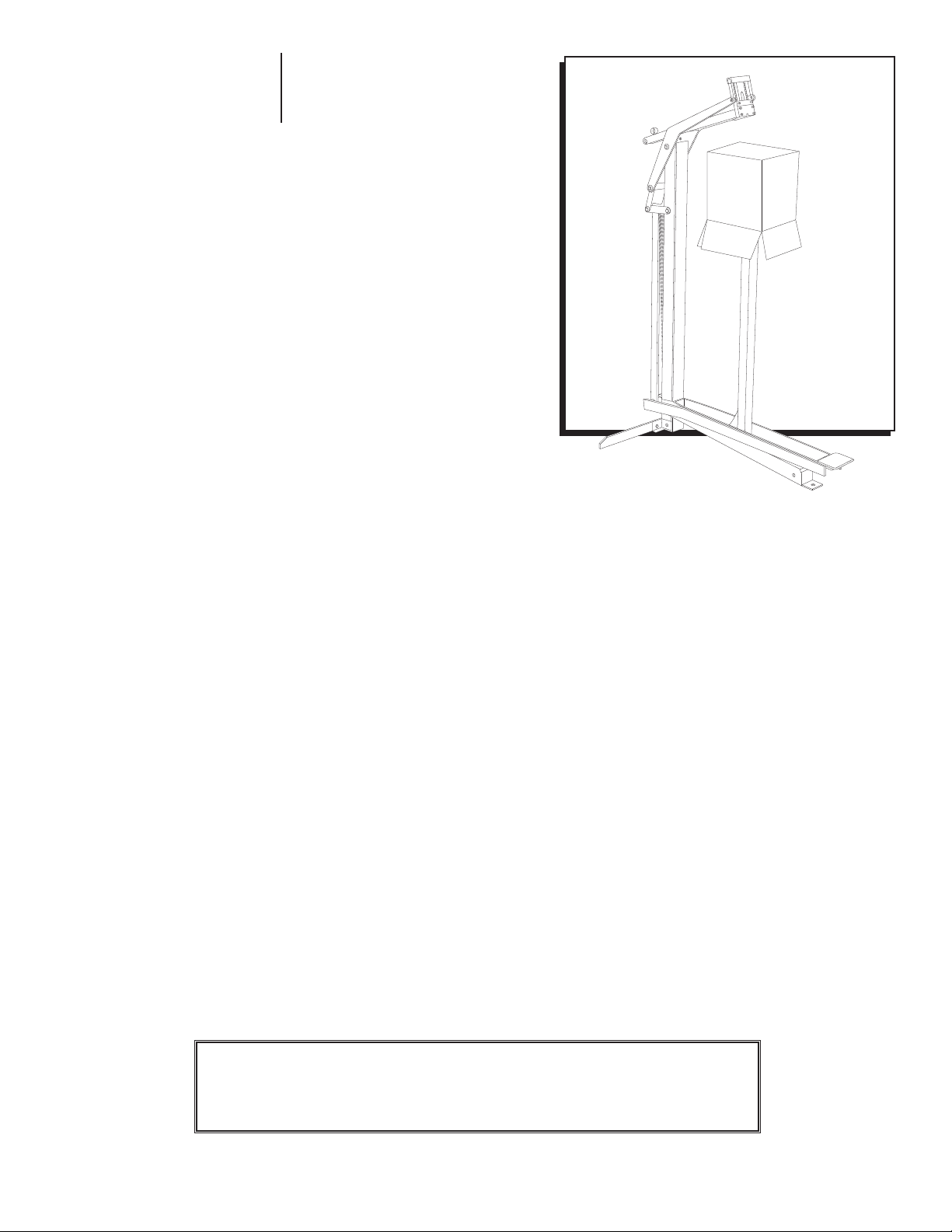
H-1980
FOOT-OPERATED
STAPLER
1-800-295-5510
uline.com
STAPLER SPECIFICATIONS
Dimensions L x W x H: 36 x 24 x 49"
Weight (without fasteners): 66 lbs.
Staple Specification: S-289 C58 Stick
Staple Specification: S-1396 C34 Stick
Staple Capacity: 200 Staples
WARNING!
Before operating this stapler familiarize yourself with the safety
warnings and instructions in this manual. Keep these instructions with
the stapler for future reference. If you have any questions, contact
Uline at 1-800-295-5510.
0813 I H -198 0PAGE 1 OF 6
Page 2

GENERAL INFORMATION
WARNING! It is important that all operators
read, understand, and practice all safety,
operating, and maintenance instructions
before using this unit to reduce risk of bodily
injury to everyone involved.
STAPLE SELECTION/CLINCH
1. Proper staple leg length selection is dependent on
the thickness and quantity of individual material
layers to be fastened. Since the head assembly is
only able to compress the top layer of corrugated
slightly, thicker materials must use longer leg staples
to penetrate all layers sufficiently and supply a
quality closure.
2. A proper clinch is attained when the staple legs are
bent sufficiently to hold the corrugated layers tightly
together without the points tearing back through the
inside corrugate liner. Excessive clinch can cause
loss of holding strength. (See Figure 1)
SAFETY
GENERAL SAFETY
It is important that you read, understand, and practice
all safety, operating, and maintenance instructions
before using this or any other stapling unit to reduce risk
of bodily injury to yourself and others in the work area.
WARNING! Employer must provide
recommended safety protection equipment
for use by operator of this unit. Must enforce
compliance with the operator safety
instructions, all other instructions contained
in this manual, and all applicable OSHA
regulations. Must provide complete training in
safe unit operation for all operators as well as
maintain an instruction manual available for
use by all unit operators.
Figure 1
EXCESSIVE CLINCH
PROPER CLINCH
3. Never operate your unit under the influence of
alcohol or drugs. Do not operate this unit if you are
excessively tired or not feeling well.
4. Do not rush or hurry your work. This may cause injury.
5. Always assume your unit contains fasteners.
6. Maintain a clean, uncluttered work area and use
sufficient lighting for safe unit operation.
7. Use only parts and fasteners recommended by
manufacturer. Others may be dangerous and could
cause your unit to malfunction.
8. Contact the manufacturer before making any
modifications to the unit.
9. Replace unit warning label if missing.
1. Wear Eye Protection. Eye protection which
conforms to American National Standards Institute
Specification ANSI 287.1 and which provides
protection against flying fasteners and debris both
from the front and side shall always be worn by the
operator and others in the work area when loading,
operating, or servicing the unit.
2. Wear Hearing Protection. Ear protection may be
required in work areas which include exposure to
high noise levels which can damage hearing. Both
user and employer should make sure necessary
hearing protection is provided and worn by the
operator and others in the work area.
UNIT LOADING SAFETY
1. Use only genuine fasteners recommended by
manufacturer. Others may be dangerous and could
cause your unit to malfunction.
2. Do not place your hand or any part of your body in
the fastener discharge area.
0813 I H -198 0PAGE 2 OF 6
Page 3

SAFETY (CONTINUED)
UNIT OPERATION SAFETY
1. Always assume unit is loaded. Never discharge
fasteners without corrugated in place. Do not
engage in horseplay or games.
2. Keep your hands and body away from the
discharge area of the unit.
3. Use care when handling unit. Do not pound or
hammer on the unit for any reason. This may
damage the body of unit causing deformations or
cracks which can be dangerous.
4. Wear proper work clothes. Do not wear neck ties,
gloves, or loose-fitting clothing when operating
pneumatic units.
1. Find a suitable place.
2. Open the packaging and stand the machine up.
OPERATING INSTRUCTIONS
UNIT MAINTENANCE SAFETY
1. Only qualified service people shall repair the unit.
2. Always remove fasteners when performing repairs.
Use only authorized spare parts for repair or
replacement.
3. Clean unit daily. A dirty unit may malfunction,
causing injury.
4. Inspect unit regularly for proper operation. Repair or
replace any damaged components at once.
5. Do not modify unit in any way.
ASSEMBLY
3. Use 6 mm Allen wrench and 13 mm wrench to
assemble the balancer (49). (See parts diagram)
4. Assemble the spring (38).
1. Pull pusher backwards until it stops on pusher pivots.
Then rotate pusher into position.
2. Insert 4 sticks of appropriate staples into magazine
from the back. Let the staples slide forward to the
front.
3. Pull pusher back to upright position and gently let
the pusher slide forward against the staples. DO NOT
let the pusher slide forward to engage staples at
high speed. It may deform staples or damage the
machine.
MAINTENANCE
1. Keep the machine clean.
2. Feed oil on every shaft before operating.
CLEARING A JAM
1. Pull the pusher backwards and rotate into position.
Then, remove all the staples.
2. Remove cover A with a 4mm hex wrench.
3. Clear the jam.
4. Put the carton into position.
NOTE: Straighten the center line of the carton
to the cover center line.
5. Press the step board set down by foot until it stoops.
Then release the step board set.
NOTE: If there is not a carton in position, do not
press the step board set down.
4. Assemble cover A.
0813 I H -198 0PAGE 3 OF 6
Page 4

PARTS DIAGRAM
507
511
508
4
504
506
9
14
15
16
512
501
1
2
3
7
502
10
26
519
50
518
27
28
30
24
23
25
21
532
520
11
8
503
530
516
12
20
22
515
517
527
521
39
526
44
38
34
35
29
48
31
33
37
525
3
32
523
49
48
524
46
17
513
533
0813 I H -198 0PAGE 4 OF 6
Page 5

PARTS LIST
# DESCRIPTION QTY. ULINE PART NO. MFG. PART NO.
1 Link 1 2
2 Tube 2 ------------ A00603401
3 Shaft E 2 ------------ A00603201
4 Link 2 2 H-1980-LINK A00600401
7 Driver Seat 1 ------------ A00600703
8 Shaft C 2 H-1980-08 A00600801
9 Driver 1 H-1980-09 A00600905
10 Spring 2 H -1980 -10 A00601002
11 Spring Shaft 1 H-1980-11 A0 0601103A
12 Magazine Seat 1 H-1980 -12 A00601203
14 Cover B 1 ------------ A00601405
15 Shaft D 1 ------------ A00601502
16 Cover A 1 ------------ A00601605
17 Bracket 1 ------------ A00607501
20 Magazine Unit 1 H-1980 -20 CMB-S-32-P3-S
21 Bracket Set 1 ------------ A00602101
22 Nut 2 ------------ A00607101
23 Right Pusher Guide 1 ------------ A00103903A
24 Rod 1 ------------ A00103203
25 Left Pusher Guide 1 ------------ A00103904A
26 Pusher Set 1 H-1980-26 A00103710A
27 Roller 1 H-1980 -27 A00103501
28 Spring 1 H-1980-28 A00602801
29 Link 3-A 2 ------------ A00602901
30 Tube 1 ------------ A00603002
31 Tube 2 ------------ A00603701
32 Shaft E 1 ------------ A00603202
33 Shaft F 1 ------------ A00603302
34 Tube 2 ------------ A00603402
35 Link 4 Set 1 ------------ A00603503A
37 Tube 2 ------------ A00603701
38 Spring 1 ------------ A00603801
39 Body Set 1 ------------ A00603904A
44 Step Board Set 1 ------------ A00604402A
46 Mold 1 ------------ A00604607
48 Shaft G 2 ------------ A00604801
49 Balancer 1 ------------ A00604901
50 Link 3-B 2 ------------ A00602903
501 E-Ring 2 ------------ BA F11 0 02
502 E-Ring 2 H-198 0 - 5 02 BAF10502
503 E-Ring 2 H-198 0 - 5 0 2 BAF10502
------------
A0060 0102
0813 I H -198 0PAGE 5 OF 6
Page 6

PARTS LIST (CONTINUED)
# DESCRIPTION QTY. ULINE PART NO. MFG. PART NO.
504 Hexagonal Socket Head Bolt 2 ------------ BAC0604102
506 Spring Pin 2 ------------ BAA060016
507 E-Ring 2 ------------ BAF10602
508 Hexagonal Socket Head Bolt 6 ------------ BAC0605102
511 Hexagonal Socket Head Bolt 6 ------------ BAC0605082
512 Locknut 1 ------------ BAD01041
513 Hexagonal Socket Flat
Counter Sunk Head Screw
515 Washer 4 ------------ BAE01052
516 Hexagonal Socket Flat
Counter Sunk Head Screw
517 Locknut 2 ------------ BAD02051
518 Spring Pin 1 H -1980-518 BA A040016
519 E-Ring 2 ------------ B A F110 02
520 E-Ring 2 ------------ B AF110 0 2
521 E-Ring 2 ------------ BA F11 0 02
523 Hexagonal Socket Head Bolt 2 ------------ BAC0408202
524 E-Ring 2 ------------ B A F110 02
525 E-Ring 2 ------------ B A F110 02
526 Locknut 2 ------------ BAD01081
527 Wave Washer 2 ------------ BAE03122
530 Spring Pin 4 ------------ BAA040008
532 Wave Washer 2 ------------ BAE03142
533 Hexagonal Socket Round Head Screw 2 ------------ BAC0904082
1 ------------ BAC0204222
2 H-1980 -516 BAC0205162
π
CHICAGO • ATLANTA • DALLAS • LOS ANGELES • MINNEAPOLIS • NYC/PHILA • SEATTLE • MEXICO • CANADA
1-80 0-295-5510
uline.com
0813 I H -198 0PAGE 6 OF 6
 Loading...