

Page 1
Para Español, vea páginas 4-6.
Pour le français, consulter les pages 7-9.
H-1485, H-1486, H-1487
π
H-1783, H-6754
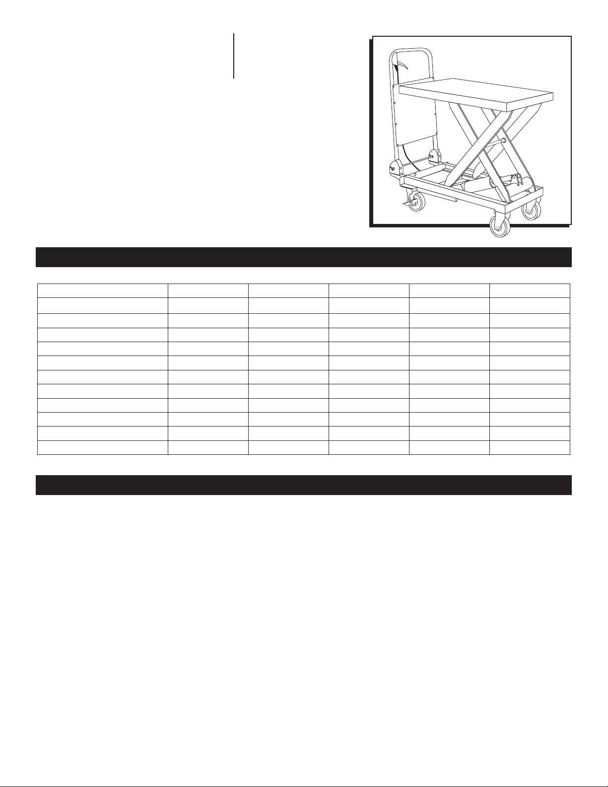
STANDARD LIFT TABLE
1-800 -295-5510
uline.com
TECHNICAL INFORMATION
SPECIFICATIONS H-1485 H-1486 H-1487 H -1783 H-6754
Capacity 330 lbs. 660 lbs. 1,100 l bs. 1,760 lbs . 1,100 lbs.
Height Raised 29" 35" 35" 39.5" 36"
Height Lowered 8.8" 11" 11" 16.5" 12.5"
Table Size 27 x 18 x 2" 32 x 20 x 2" 32 x 20 x 2" 39½ x 20 x 2" 63 x 31.5 x 2"
Total Height 37" 39" 39" 39" 39"
Overall Length 31" 37" 37" 46" 65"
Foot Pedal Cycles to Max Height 25 32 45 56 40
Wheel Diameter 4" 5" 5" 6" 5"
Weight 101 lbs. 165 lbs. 187 lbs. 254 lbs. 296 lbs.
Working Volume of Oil Cylinder 138 ml 164 ml 164 ml 157 m l 200 ml
Oil Capacity 210 ml 250 ml 250 ml 240 ml 300 ml
GENERAL INFORMATION
1. Read all instructions carefully before operating the
lift table.
2. DO NOT overload the lift table and always operate
it within the rated load. Overloading will cause
damage to the lift table and the operator.
3. DO NOT stand or sit on the table to work.
4. DO NOT put hands or feet under the table when
lowering.
5. Apply the brakes while loading to prevent the table
from moving.
6. The load must be distributed uniformly across the
whole table.
7. DO NOT load loose or unstable loads onto the table.
8. DO NOT leave the table loaded for extended
periods of time.
PAGE 1 OF 9 1118 IH-1485
9. DO NOT move the truck while lifting.
10. The table should only be used on flat solid surfaces.
11. Make sure not to overload the table when it is in
the raised position. The safety valve only works as
the table is lifted. Overloading in the raised position
may damage the table.
12. When loading and unloading goods in the raised
position, do not drag loads across the table.
This may cause offset loading and the table may
turn over.
13. When maintaining and repairing the table, the
stand bar should be used to support the fork arm in
order to prevent table from falling. There should not
be a load on table while maintaining and repairing
the table.
Page 2
ASSEMBLY
1. These are folding tables. They can only be operated
if the handle is in the upright position.
2. The foot lever is dismantled when shipped. It must be
attached to lift table before operating.
8
1
FOOT LEVER INSTALLATION
Foot lever mounting: insert the foot pedal into the hole
of the square bar. Fix the foot pedal with a
bolt, flat washer a lock washer, and a nut. Tighten the
nut with a wrench.
2
7
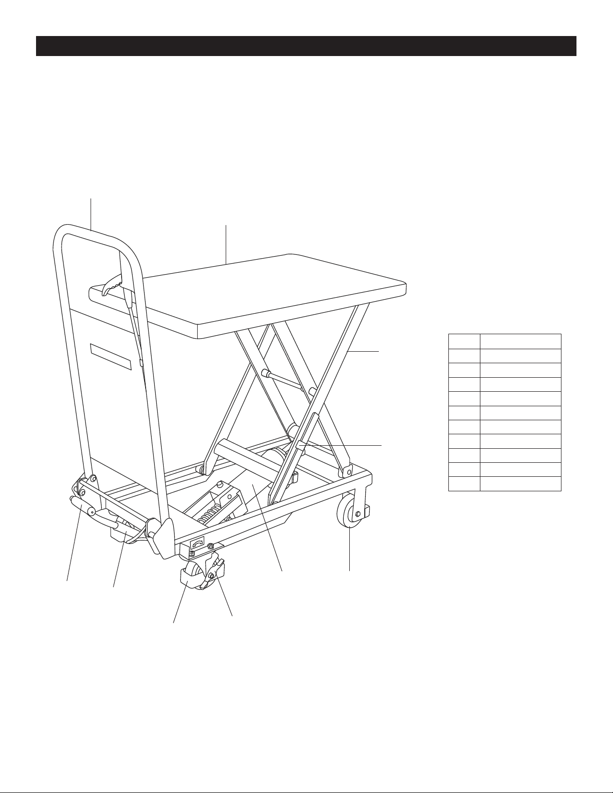
# PART NAME
1 Loading Platform
2 Lift Mechanism
3 Hydraulic Cylinder
4 Swivel Caster
5 Rigid Caster
6 Brake
7 Safety Stand Bar
8 Handle
9 Foot Pedal
10 Square Bar
9
PAGE 2 OF 9 1118 IH-1485
10
4
6
3
5
Page 3
MAINTENANCE
It is very important to conduct necessary maintenance
and upkeep so as to prolong the service life and
safety of the lift table. Please check the lift table before
operation accordingly:
1. Check for any distortion or bending of any parts of
the lift table.
2. Check the brake of the truck and the condition of
the wheels.
3. Check for oil leakage in the hydraulic system.
4. Add or fill lubricant to each friction surface before
daily operation.
TROUBLESHOOTING
OPERATING ISSUE CAUSES RECOMMENDATIONS
Does not reach the full lift height.
1) Steel ball of the check-valve is not
fully seating.
2) Firing pin does not allow the steel
ball to fully seat.
3) Low hydraulic oil.
5. If there is any failure, the lift table should be
repaired at once before it is put into use again.
6. Change the hydraulic oil every twelve months.
Choose appropriate hydraulic oil according to the
climate conditions.
7. To change the hydraulic oil:
a. Unscrew sealing screw with a wrench.
b. Lift the hand lever.
c. Twist off screw of the oil plug and fill pump with
hydraulic oil.
1) Clean the valve opening and
replace the steel ball.
2) Adjust the tension rate of the steel
wire connected to the hand lever to
adjust the seating of the firing pin.
3) Add hydraulic oil.
The table rises then descends.
The table board does not descend.
Oil leakage at firing pin.
Oil leakage at pump.
Table will not rise.
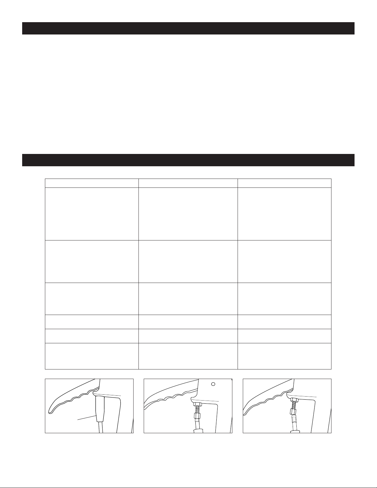
Figure 1 Figure 2 Figure 3
Cable
with Boot
1) Steel ball of the check-valve is not
fully seating.
2) Firing pin does not allow the steel
ball to fully seat.
The travel of the firing pin is not enough
to open the steel ball.
The O-ring is damaged. Change the O-ring.
The seal ring is damaged. Change the seal ring.
Cable may be disconnected. Ensure cable with silver sleeve is
Correct
Cable Insertion
1) Clean the valve opening and
change the steel ball.
2) Adjust the tension rate of the steel
wire connected to the hand lever
to adjust the seating of firing pin.
Adjust the tension rate of the steel
wire rope to make firing pin at
suitable place and apply lubricant
to the pin.
terminating inside of nut.
(See Figures 1-3)
Incorrect
Cable Insertion
π
CHICAGO • ATLANTA • DALLAS • LOS ANGELES • MINNEAPOLIS • NYC/PHILA • SEATTLE • MEXICO • CANADA
1-80 0 -295-5510
PAGE 3 OF 9 1118 IH-1485
uline.com
Page 4

π
H-1783, H-6754
01-800 -295-5510
uline.mx
MESA DE ELEVACIÓN
ESTÁNDAR
INFORMACIÓN TÉCNICA
ESPECIFICACIONES H-1485 H-1486 H-1487 H -1783 H-6754
Capacidad 150 kg (330 lbs.) 300 kg (660 lbs.) 499 kg (1,100 lbs.) 798.3 kg (1,760 lbs.) 499 kg (1,100 lbs.)
Altura Máxima 73.66 cm (29") 88.9 cm (35") 88.9 cm (35") 1 m (39.5") 91.4 cm (36")
Altura Mínima 22.35 cm (8.8") 27.9 cm (11") 27.9 cm (11") 41.9 cm (16.5") 31.75 cm (12.5")
H-1485, H-1486, H-1487
Tamaño de la mesa
Altura total 94 cm (37") 99 cm (39") 99 cm (39") 99 cm (39") 99 cm (39")
Largo general 78.7 cm (31") 94 cm (37") 94 cm (37") 117 cm (46") 165 cm (65")
Ciclos del pedal hasta la altura
máx.
Diámetro de llanta 10.2 cm (4") 12.7 cm (5") 12.7 cm (5") 15.2 cm (6") 12.7 cm (5")
Peso 46 kg (101 lbs.) 75 kg (165 lbs.) 84.82 kg (187 lbs.) 115.1 kg (254 lbs.) 134.26 kg (296 lbs.)
Volumen de funcionamiento del
cilindro de aceite
Capacidad de aceite 210 ml 250 ml 250 ml 240 ml 300 ml
68.6 x 45.7 x 5.1 cm
(27 x 18 x 2")
25 32 45 56 40
138 ml 164 ml 164 ml 157 m l 200 ml
81.3 x 51 x 5.1 cm
(32 x 20 x 2")
81.3 x 51 x 5.1 cm
(32 x 20 x 2")
100.3 x 50.8 x 5.1 cm
(39½ x 20 x 2")
160.02 x 80 x 5.1 cm
(63 x 31.5 x 2")
INFORMACIÓN GENERAL
1. Lea con cuidado todas las instrucciones antes de
utilizar la mesa de elevación.
2. NO sobrecargue la mesa de elevación y hágala
funcionar siempre con el peso indicado. La
sobrecarga causará daños a la mesa de elevación
y al operador.
3. NO se ponga de pie ni se siente en la mesa para
trabajar.
4. NO ponga las manos o los pies debajo de la mesa
al bajarla.
5. Ponga los frenos al cargarla para evitar que la
mesa se desplace.
6. La carga deberá repartirse uniformemente por toda
la mesa.
7. NO cargue pesos sueltos o inestables sobre la mesa.
8. NO deje la mesa cargada durante períodos
prolongados.
PAGE 4 OF 9 1118 IH-1485
9. NO mueva el carrito mientras eleva.
10. La mesa solo debe utilizarse sobre superficies
planas y sólidas.
11. Asegúrese de no sobrecargar la mesa cuando
se encuentre en posición elevada. La válvula de
seguridad solo funciona mientras se eleva la mesa.
Sobrecargar la mesa en posición elevada podría
dañarla.
12. Al cargar o descargar artículos en posición elevada,
no arrastre las cargas a lo largo de la mesa.
Esto puede desequilibrar la carga y la mesa podría
volcarse.
13. Al realizar tareas de mantenimiento y reparación
a la mesa, la barra vertical deberá usarse para
apoyar el brazo de la horquilla y evitar que la mesa
se caiga. No debe haber carga alguna sobre la
mesa mientras se realizan tareas de mantenimiento
o se repara.
Page 5

ENSAMBLE
1. Estas son mesas plegables. Solo pueden funcionar
si el asa está en posición vertical.
2. La palanca de pie se desmonta para el envío.
Debe colocarse en la mesa de elevación antes de
hacerla funcionar.
8
1
COLOCACIÓN DE LA PALANCA DE PIE
Montaje de la palanca de pie: inserte el pedal en el
orificio ubicado en la barra cuadrada. Fije el pedal
con un perno, una rondana plana una rondana de
seguridad y una tuerca. Apriete la tuerca con una llave.
2
7
# NOMBRE DE PARTE
1 Plataforma de Carga
2 Mecanismo de Elevación
3 Cilindro Hidráulico
4 Rueda Giratoria
5 Rueda Rígida
6 Freno
7
8 Asa
9 Pedal
10 Barra Cuadrada
Barra de Soporte
de Seguridad
9
PAGE 5 OF 9 1118 IH-1485
10
4
6
3
5
Page 6

MANTENIMIENTO
Es muy importante realizar el mantenimiento necesario
para prolongar la vida útil y la seguridad de la mesa
de elevación. Por favor, verifique la mesa de elevación
antes de hacerla funcionar:
1. Verifique no haya partes de la mesa de elevación
que se hayan deformado o doblado.
2. Verifique el estado del freno del carrito y de las llantas.
3. Verifique que no haya fugas de aceite en el sistema
hidráulico.
4. Agregue o rellene con lubricante cada una de las
superficies de fricción antes del funcionamiento diario.
SOLUCIÓN DE PROBLEMAS
PROBLEMA DE FUNCIONAMIENTO CAUSAS RECOMENDACIONES
No alcanza la altura máxima de
elevación.
1)
La bola de acero de la válvula de
control no se asienta completamente.
2) El perno de disparo no permite
que la bola de acero se asiente
completamente.
3) El nivel de aceite hidráulico es bajo.
5. En caso de fallos, la mesa de elevación debe
repararse de inmediato antes de volverse a utilizar.
6. Cambie el aceite hidráulico cada doce meses. Elija
el aceite hidráulico adecuado en función de las
condiciones climáticas.
7. Para cambiar el aceite hidráulico:
a. Desatornille el tornillo de sellado con una llave.
b. Levante la palanca de mano.
c. Gire el tornillo del tapón de aceite hasta quitarlo
y llene la bomba con aceite hidráulico.
1) Limpie la abertura de la válvula y
reemplace la bola de acero.
2
) Ajuste la tasa de tensión del
alambre de acero conectado a la
palanca de mano para ajustar el
asiento del perno de disparo
3) Agregue aceite hidráulico.
.
La mesa se eleva y luego
desciende.
La tabla de la mesa no desciende.
Fuga de aceite en el perno de
disparo.
Fuga de aceite en la bomba.
La mesa no se eleva.
Diagrama 1 Diagrama 2 Diagrama 3
1)
La bola de acero de la válvula de
control no se asienta completamente.
2) La clavija de disparo no permite
que la bola de acero se asiente
completamente.
El recorrido del perno de disparo no es
suficiente para abrir la bola de acero.
El anillo-O está dañado. Cambie el anillo-O.
El empaque está dañado. Cambie el empaque.
El cable podría estar desconectado. Asegúrese de que el cable con el
1) Limpie la abertura de la válvula y
cambie la bola de acero.
2) Ajuste la tasa de tensión del
alambre de acero conectado a
la palanca de mano para ajustar
el asiento de la clavija de disparo.
Ajuste la tasa de tensión de la
cuerda del alambre de acero
para colocar la clavija de disparo
en una posición óptima y aplique
lubricante a la clavija.
recubrimiento plateado termine
de la tuerca. (Vea Diagramas 1-3)
dentro
π
Cable
con Cubierta
Conexión
Correcta
del Cable
CHICAGO • ATLANTA • DALLAS • LOS ANGELES • MINNEAPOLIS • NYC/PHILA • SEATTLE • MEXICO • CANADA
Conexión
Incorrecta
del Cable
01-800-295-5510
PAGE 6 OF 9 1118 IH-1485
uline.mx
Page 7

π
H-1783, H-6754
1-800 -295-5510
uline.ca
TABLE ÉLÉVATRICE
STANDARD
CARACTÉRISTIQUES TECHNIQUES
SPÉCIFICATIONS H-1485 H-1486 H-1487 H -1783 H-6754
Capacité 149,7 kg (330 lb) 299,4 kg (660 lb) 499 kg (1100 lb) 798,3kg (1760 lb) 499 kg (1 100 lb)
Hauteur élevée 73,7cm (29po) 88,9cm (35po) 88,9cm (35po) 100,3cm (39,5po) 91,4 cm (36 po)
Hauteur abaissée 22,4cm (8,8po) 27,9cm (11po) 27,9cm (11po) 41,9cm (16,5po) 31,75 cm (12.5 po)
H-1485, H-1486, H-1487
Dimensions de la table
Hauteur totale 94cm (37po) 99cm (39po) 99cm (39po) 99cm (39po) 99 cm (39 po)
Longueur totale 78,7cm (31po) 94cm (37po) 94cm (37po) 116,8cm (46po) 165 cm (65 po)
Cycles du levier à pied jusqu'à la
hauteur maximale
Diamètre des roues 10,2cm (4po) 12,7cm (5po) 12,7cm (5po) 15,2po (6po) 12,7 cm (5 po)
Poids 45,8kg (101lb) 74,8kg (165lb) 84,8kg (187lb) 115,2kg (254lb) 134,26 kg (296 lb)
Volume fonctionnel du cylindre
à huile
Volume maximal d’huile 210 ml 250 ml 250 ml 240 ml 300 ml
68,6 x 45,7 x 5,1cm
(27 x 18 x 2po)
25 32 45 56 40
138 ml 164 ml 164 m l 157 ml 200 ml
81,3 x 50,8 x 5,1cm
(32 x 20 x 2po)
81,3 x 50,8 x 5,1cm
(32 x 20 x 2po)
100,3 x 50,8 x 5,1cm
(39½ x 20 x 2po)
160,02 x 80 x 5,1 cm
(63 x 31 ½ x 2 po)
RENSEIGNEMENTS GÉNÉRAUX
1. Lisez soigneusement toutes les instructions avant
d'utiliser la table élévatrice.
2. NE surchargez PAS la table élévatrice et respectez
toujours sa charge nominale. Une surcharge risque
d'endommager la table élévatrice et de blesser
l’utilisateur.
3. NE vous tenez PAS debout ou ne vous assoyez pas
sur la table pour travailler.
4. NE placez PAS vos mains ou vos pieds sous la table
en l'abaissant.
5. Appliquez les freins lors du chargement pour
empêcher la table de se déplacer.
6. La charge doit être répartie uniformément sur toute
la table.
7. NE chargez PAS des charges lâches ou instables sur
la table.
8. NE laissez PAS la table chargée pendant de longues
périodes.
PAGE 7 OF 9 1118 IH-1485
9. NE bougez PAS le chariot lors du levage.
10. La table doit être utilisée uniquement sur des
surfaces planes et solides.
11. Assurez-vous de ne pas surcharger la table
lorsqu'elle est en position élevée. La soupape de
sécurité fonctionne uniquement lors du levage. Une
surcharge en position élevée risque d'endommager
la table.
12. Lors du chargement et du déchargement des
marchandises en position élevée, ne traînez pas
les charges sur la table. Cela peut déséquilibrer le
chargement et renverser la table.
13. Lors de l'entretien et la réparation de la table, la
barre de soutien doit être utilisée pour soutenir
le bras de fourche afin d'empêcher la table de
tomber. La table ne doit pas supporter une charge
lors de l'entretien et la réparation de la table.
Page 8

ASSEMBLAGE
1. Ces tables sont pliantes. Elles peuvent seulement
être utilisées si la poignée est en position verticale.
2. Le levier à pied est démonté lors de la livraison.
Il doit être fixé sur la table élévatrice avant son
utilisation.
8
1
INSTALLATION DU LEVIER À PIED
Assemblage du levier à pied : Insérez le levier à pied
dans le trou de la barre carrée. Fixez le levier à pied à
l'aide d'un boulon, d'une rondelle plate, d'une rondelle de
blocage et d'un écrou. Serrez l'écrou à l'aide d'une clé.
2
7
# NOM DE PIÈCES
1 Plate-forme de chargement
2 Mécanisme de levage
3 Cylindre hydraulique
4 Roulette pivotante
5 Roulette fixe
6 Frein
7 Barre de sécurité
8 Poignée
9 Levier à pied
10 Barre carrée
9
PAGE 8 OF 9 1118 IH-1485
10
4
6
3
5
Page 9

ENTRETIEN
Il est très important d'effectuer l'entretien nécessaire
afin de prolonger la durée de vie et la sécurité de la
table élévatrice. Veuillez vérifier les points suivants avant
d’utiliser la table:
1. Assurez-vous que les pièces de la table élévatrice
ne sont pas déformées ou pliées.
2. Vérifiez les freins du chariot et l'état des roues.
3. Vérifiez s'il y a des fuites d'huile dans le système
hydraulique.
4. Lubrifiez chaque surface de frottement avant
l'utilisation quotidienne.
DÉPANNAGE
PROBLÈME CAUSES RECOMMANDATIONS
La table n'atteint pas la hauteur
maximale.
1)
La bille en acier du clapet anti-retour
n’est pas appuyée complètement.
2) La goupille de déclenchement
empêche la bille en acier de
s’appuyer complètement.
3) Le niveau d'huile hydraulique est bas.
5. En cas de défaillance, la table élévatrice doit être
réparée immédiatement avant d'être utilisée de nouveau.
6. Changez l'huile hydraulique tous les douze mois.
Choisissez l'huile hydraulique appropriée en fonction
des conditions climatiques.
7. Pour changer l'huile hydraulique:
a. Dévissez la vis d'étanchéité à l’aide d'une clé.
b. Levez le levier à main.
c. Dévissez la vis du bouchon d'huile et remplissez
la pompe avec de l'huile hydraulique.
1)
Nettoyez l'ouverture de la soupape
et replacez la bille en acier.
2) Réglez le niveau de tension du fil
d'acier relié au levier à main pour
régler l'appui sur la goupille de
déclenchement.
3) Ajoutez de l'huile hydraulique.
La table s'élève puis redescend.
Le plateau de la table ne descend
pas.
Fuites d'huile au niveau de la
goupille de déclenchement.
Fuites d'huile au niveau de la
pompe.
La table ne s'élève pas.
Figure 1 Figure 2 Figure 3
1) La bille en acier du clapet
anti-retour n'est pas appuyée
complètement.
2) La goupille de déclenchement
empêche la bille en acier de
s'appuyer complètement.
La goupille de déclenchement ne se
déplace pas suffisamment pour ouvrir
la bille en acier.
Le joint torique est endommagé. Changez le joint torique.
La bague d'étanchéité est
endommagée.
Le câble est peut-être débranché. Assurez-vous que le câble avec le
1) Nettoyez l'ouverture de la
soupape et changez la bille en
acier.
2) Réglez le niveau de tension du fil
d'acier relié au levier à main pour
régler l'appui sur la goupille de
déclenchement.
Réglez le niveau de tension du câble
en acier pour déplacer la goupille
de déclenchement à l'endroit
approprié et lubrifiez la goupille.
Changez la bague d'étanchéité.
manchon argenté n'excède pas
l'intérieur de l'écrou. (Voir Figures 1-3)
π
Câble
avec gaine
Insertion
adéquate
du câble
CHICAGO • ATLANTA • DALLAS • LOS ANGELES • MINNEAPOLIS • NYC/PHILA • SEATTLE • MEXICO • CANADA
Insertion
inadéquate
du câble
1-80 0 -295-5510
PAGE 9 OF 9 1118 IH-1485
uline.ca
 Loading...