

Page 1
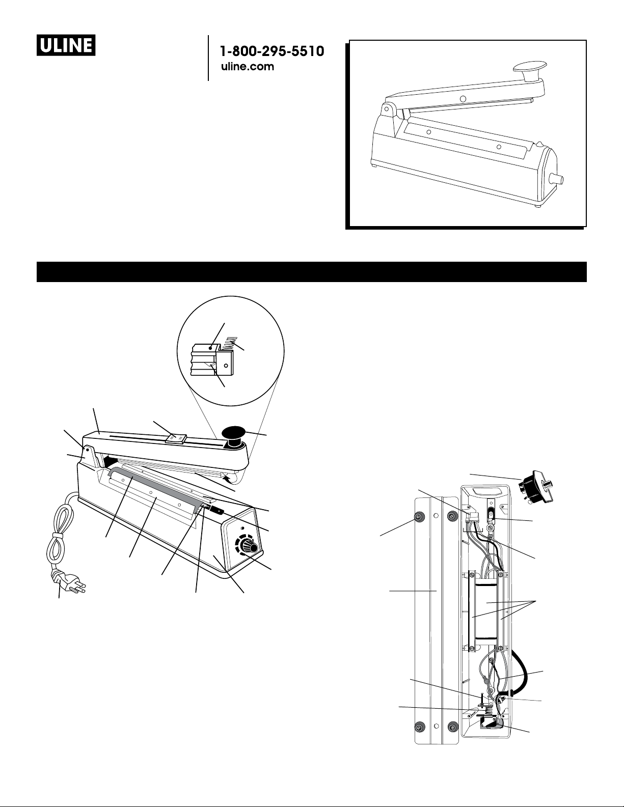
H-161, H-163, H-190
BOTTOM VIEW
Timer Assembly
H-293, H-306, H-458
H-963, H-1029, H-1252
Impulse sealers
Para Español, vea páginas 5-8.
Pour le français, consulter les pages 9-12.
PARTS
Sealing Arm
Hinge Pin
Hinge
Bracket
Power Cord
Bracket Assembly
Teflon Cover
Front Metal Plate
Heating Element
SEALING ARM
(H-161, H-293, H-963
and H-1252 only)
Cutting Blade
(H-161, H-293, H-963
and H-1252 only)
Lower Teflon Tape
Pressure Plate
Assembly
Pressure
Plate
Spring
Cutting Blade
Rubber Pressure Pad
π
5
4
3
2
1
Sealer Body
Handle Knob
Rear Metal
Plate
Heating
6
Element
Cover
Timer Assembly
Timer Connector
Plug
Rubber Foot
Base Plate
Bow
Spring
Assembly
Internal
Wiring
Transformer
& Support
Brackets
Microswitch
Adjustment
Screw
Arm Return
Ground
Wire
(green)
Wire Nut
Spring
Microswitch
Assembly
PAGE 1 OF 12 0314 IH-161
Page 2
OPERATING INSTRUCTIONS
1. Plug the power cord into the outlet and set the timer
knob to the thickness of the materials to be sealed.
(See Recommended Settings Table)
2. Put poly bag on the sealing platform and push down
the sealing arm. The sealer will automatically control
the seal time.
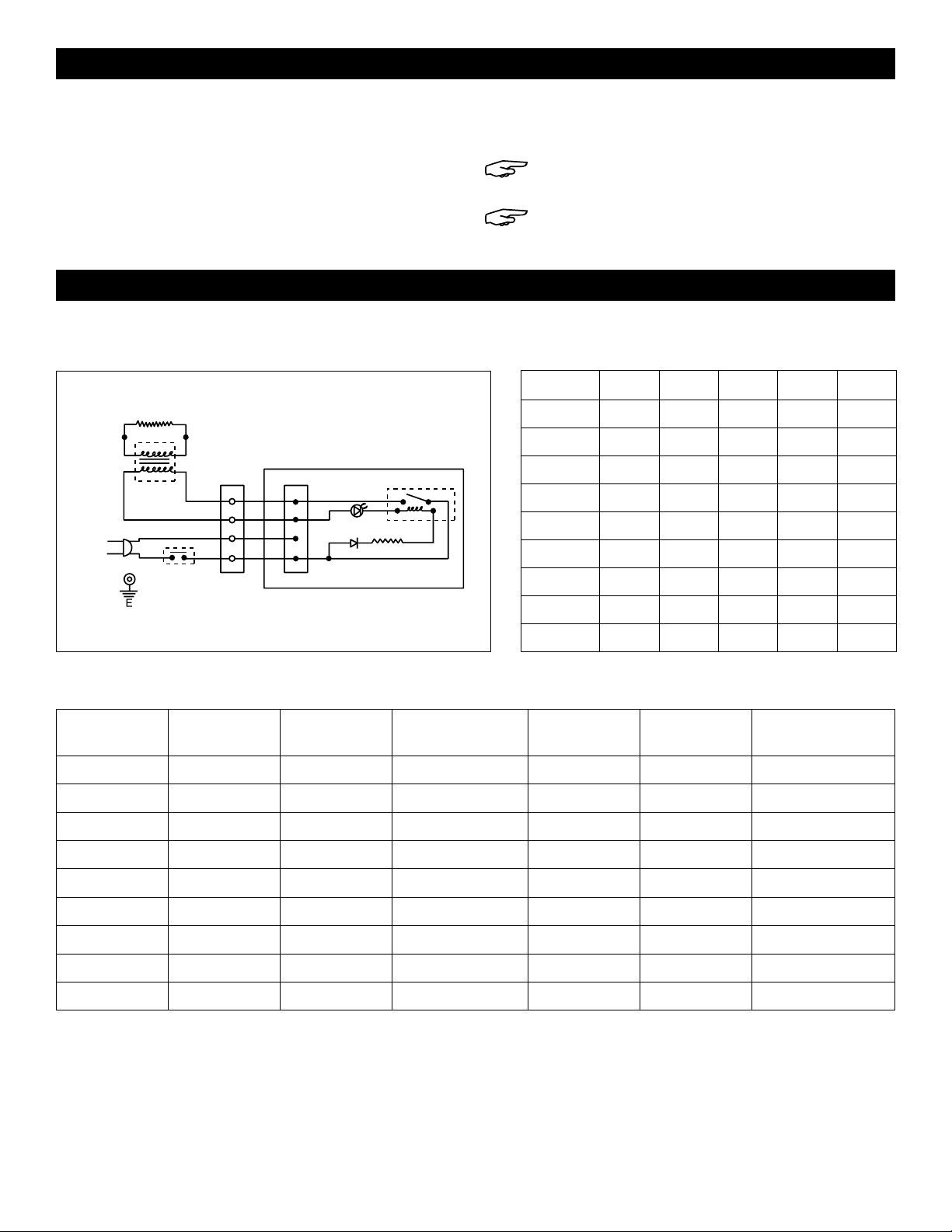
SPECIFICATIONS
Heating Element
Transformer
Relay DC24V
Sealing Light
D
Timer
R
Source
N
L
Microswitch
Connector
Control P.C.B
3. After 1 to 2 seconds, slide the cutter to trim the bag.
(Only on H-161 and H-293) Release the sealing arm.
NOTE: The higher the number on the dial, the
longer the heat sealing time.
NOTE: Sealing is complete when the light
turns off.
RECOMMENDED SETTINGSCONNECTION DIAGRAM
SEALER 1 MIL 2 MIL 3 MIL 4 MIL 6 MIL
H-161 3 3 3 4 5
H-163 3 3 3 4 5
H-190 3 3 3.5 4 5.5
H-293 3 3 3.5 4 5.5
H-306 3 3 3.5 4 5.5
H-458 3 3 3 4 5
H-963 3 3 3.5 4 5
H-1029 3 3 3.5 4 5.5
H-1252 3 3 3.5 4 5
SEALER SPECIFICATIONS
MODEL SOURCE IMPULSE
POWER
H-161 120 V 410 W 8" 6 Mil 7.7 lb s . 3.2 x 15 x 6.3"
H-163 120 V 410 W 8" 6 Mil 5.8 lbs. 3.2 x 12.6 x 5.9"
H-190 120 V 580 W 12" 6 Mil 8.5 lbs. 3.3 x 17.8 x 7.4"
H-293 120 V 580 W 12 " 6 Mil 10.1 lbs. 3.2 x 17.9 x 7.4"
H-306 120 V 670 W 16" 6 Mil 9.9 lbs. 3 x 21 x 7"
H-458 120 V 160 W 4" 6 Mil 3.7 lbs. 2.8 x 8.3 x 5.9"
H-963 120 V 670 W 16" 6 Mil 11.9 l b s . 3.2 x 21.8 x 7.3"
H-1029 120 V 870 W 20" 6 Mil 13 l bs. 4.5 x 28 x 7.8"
H-1252 120 V 870 W 20" 6 Mil 13 lb s. 3.2 x 25.9 x 7.4"
MAX. SEAL
LENGTH
MAX. SEAL
THICKNESS
WEIGHT DIMENSIONS
PAGE 2 OF 12 0314 IH-161
Page 3
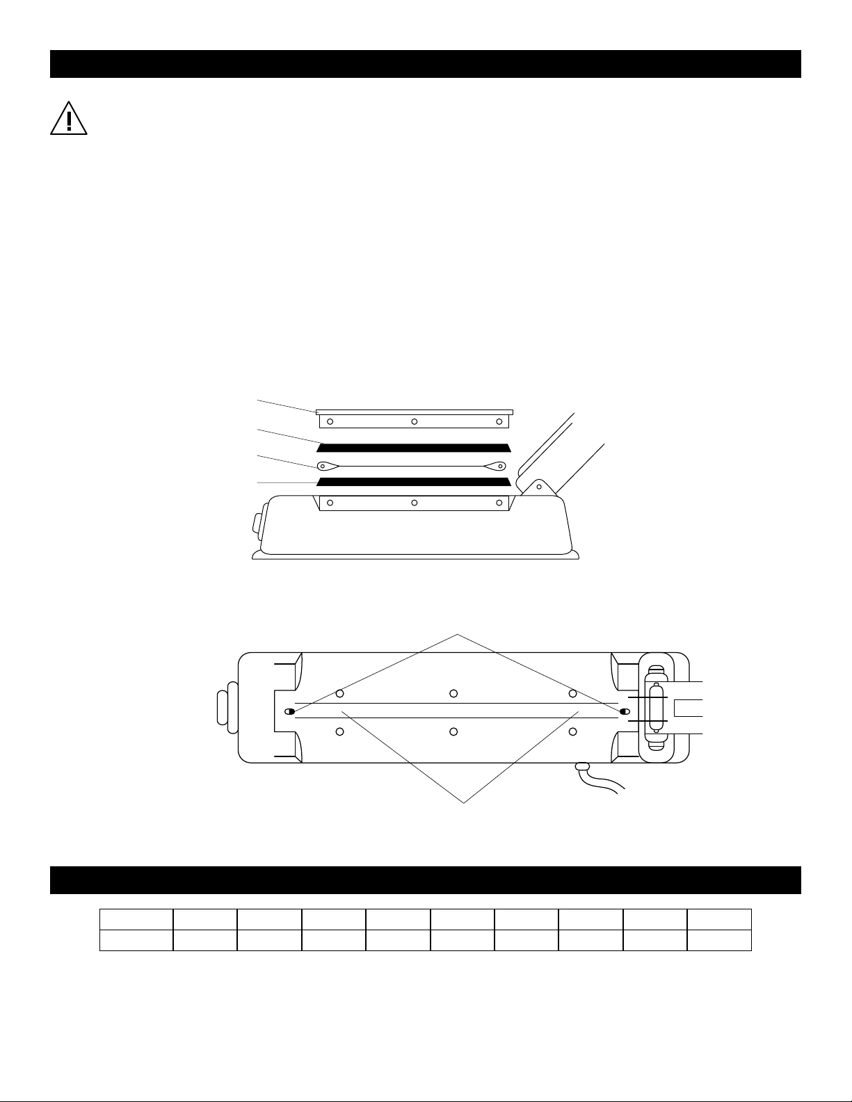
TAPE AND HEATING ELEMENT REPLACEMENT INSTRUCTIONS
CAUTION! Unplug sealer from socket before
proceeding.
1. Remove screws along with the cover plates (A)
and top teflon cover (B). Remove element (C) from
terminal posts. (See Figure 1)
2. If bottom adhesive teflon tape (D) is worn, burned or
ripped, it needs to be changed. Teflon tape keeps
the element insulated from the sealer housing to
ensure proper sealer operation. (See Figure 1)
If this tape is not worn, go to step 5.
3. After removal of metal cover plates, teflon tapes
and element, clean sealing surface (E) with cleaner
until free of glue and debris. Adhesive remover is
recommended. (See Figure 2)
A
B
C
D
4. Peel off backing of adhesive teflon tape. Apply
evenly onto sealer. Excess tape should extend all
the way to the terminal posts (F). If the element
touches any metal, the sealer will short out.
(See Figure 2)
5. Attach new heating element.
6. Reassemble in reverse of step 1. Teflon cover must
be flush against the sealer before replacing cover
plates.
SIDE VIEW
MODEL
REPAIR KIT
Figure 1
F
TOP VIEW
Figure 2
E
REPLACEMENT PARTS
H-161 H-163 H-190 H-293 H-306 H-458 H-963 H-1029 H-1252
H-495 H-164 H-191 H-294 H-307 H-471 H-964 H-1042 H -1253
PAGE 3 OF 12 0314 IH-161
Page 4
ADDITIONAL INFORMATION
• Always keep the sealing platform clean.
• Do not use water to clean the sealing platform.
• A short circuit will occur if the bottom teflon cloth
strip wears out. Each time you replace the heating
element or the top teflon cover, check the bottom
teflon tape for wear and damage.
• Only use ULINE replacement parts.
• A worn rubber pressure pad (under the handle) will
influence the quality of the seats. The rubber pad
should be periodically checked for uneven wear.
CAUTION! To provide continued protection
against risk of electric shock, connect to
properly grounded outlets only.
• If the bag seal is damaged or broken, it is because
the heating time is too long. Reset the timer knob to a
lower number.
• If the plastic bag sticks to the sealing arm, it was
because there was not enough cooling time. Keep
the arm down for a longer period of time after the
light turns off.
• It is okay to leave the unit plugged in. The unit is off
unless the sealing arm is down.
• Information regarding potential risks of fire, electric
shock, or injury to persons that are capable of
occurring due to use of the product. The instructions
shall caution the user to place the product and
connected cord so that it is not likely that the product
will be overturned.
• Information regarding the potential risks of electric
shock due to overfilling, the replacement of a lamp,
or cleaning the product without disconnecting the
power-supply cord.
• Instructions regarding the cleaning of the product,
including any necessity for disassembly (and
reassembly).
• Close supervision is required when this product is used
near children.
π
CHICAGO • ATLANTA • DALLAS • LOS ANGELES • MINNEAPOLIS • NYC/PHILA • SEATTLE • MEXICO • CANADA
1-800-295- 5510
PAGE 4 OF 12 0314 IH-161
uline.com
Page 5

H-161, H-163, H-190
π
2
1
3
4
5
6
Brazo de Sellado
Ensamble del
Soporte de la
Navaja de Corte
(H-161, H-293, H-963 y
H-1252 solamente)
Perilla de la Asa
VISTA INFERIOR DEL
BRAZO DE SELLADO
(H-161, H-293, H-963 y
H-1252 solamente)
Almohadilla de
Goma de Presión
Placa de
Metal Posterior
Ensamble del
Temporizador
Cuerpo de la
Selladora
Resistencia
Placa de Metal Frontal
Cubierta de Teflón
Cable
Pasador
de Bisagra
Soporte
de Bisagra
Cinta Inferior
de Teflón
Cubierta de
la Resistencia
Ensamble de la
Placa de Presión
Resorte de
la Placa de
Presión
Navaja de Corte
Ensamble del
H-293, H-306, H-458
H-963, H-1029, H-1252
SELLADORAS
DE IMPULSO
01-80 0 -295-5510
uline.mx
PARTES
Enchufe del
Temporizador
Pata de Goma
Placa de
la Base
Tornillo de
PAGE 5 OF 12 0314 IH-161
Ajuste del
Microinterruptor
Resorte
del Brazo
Temporizador
Ensamble
del Resorte
Cableado
Interno
Transformador
y Soportes
Cable
de Tierra
(verde)
Tuerca
para Cable
Ensamble del
Microinterruptor
Page 6

FUNCIONAMIENTO
1. Enchufe el cable al tomacorriente y configure el
temporizador de acuerdo al material que va a sellar.
(Vea Tabla de Configuraciones Recomendadas)
2. Coloque una bolsa de polietileno en la plataforma
de sellado y presione hacia abajo el brazo de
sellado. La selladora automáticamente controlará
el tiempo de sellado.
ESPECIFICACIONES
DIAGRAMA DE CONEXIÓN
Resistencia
Transformador
Relevador DC24V
Luz de Sellado
D
Temporizador
R
Fuente
N
L
Microinterruptor
Conector
Control P.C.B.
3. Después de 1 a 2 segundos, deslice la navaja para
cortar la bolsa (solo en H-161 y H-293). Libere el brazo
de sellado.
NOTA: Mientras mayor sea el número en
el temporizador, mayor será el tiempo del
termosellado.
NOTA: El sellado termina cuando la luz se apaga.
CONFIGURACIONES RECOMENDADAS
SELLADORA 1 MIL 2 MIL 3 MIL 4 MIL 6 MIL
H-161 3 3 3 4 5
H-163 3 3 3 4 5
H-190 3 3 3.5 4 5.5
H-293 3 3 3.5 4 5.5
H-306 3 3 3.5 4 5.5
H-458 3 3 3 4 5
H-963 3 3 3.5 4 5
H-1029 3 3 3.5 4 5.5
ESPECIFICACIONES DE LA SELLADORA
MODELO FUENTE POTENCIA DE
IMPULSO
H-161 120 V 410 W 20 cm (8") 6 Mil 3.5 kg (7.7 lbs.) 8.1 x 38.1 x 16 cm
H-163 120 V 410 W 20 cm (8") 6 Mil 2.6 kg (5.8 lbs.) 8.1 x 32 x 15 cm
H-190 120 V 580 W 30 cm (12") 6 Mil 3.9 kg (8.5 lbs.) 8.4 x 45.2 x 18.8 cm
H-293 120 V 580 W 30 cm (12") 6 Mil 4.6 kg (10.1 lbs.) 8.1 x 45.5 x 18.8 cm
H-306 120 V 670 W 40 cm (16") 6 Mil 4.5 kg (9.9 lbs.) 7.6 x 53.3 x 17.8 cm
H-458 120 V 160 W 10 cm (4") 6 Mil 1.7 kg (3.7 lbs.) 7.1 x 21.1 x 15 cm
H-963 12 0 V 670 W 40 cm (16") 6 Mil 5.4 kg (11.9 lbs.) 8.1 x 55.4 x 18.5 cm
H-1029 120 V 870 W 52 cm (20") 6 Mil 5.9 kg (13 lbs.) 11.4 x 71.1 x 19.8 cm
LARGO MÁX. DE
SELLADO
H-1252 3 3 3.5 4 5
GROSOR MÁX.
PESO DIMENSIONES
DE SELLADO
(3.2 x 15 x 6.3")
(3.2 x 12.6 x 5.9")
(3.3 x 17.8 x 7.4")
(3.2 x 17.9 x 7.4")
(3 x 21 x 7")
(2.8 x 8.3 x 5.9")
(3.2 x 21.8 x 7.3")
(4.5 x 28 x 7.8")
H-1252 120 V 870 W 52 cm (20") 6 Mil 5.9 kg (13 lbs.) 8.1 x 25.8 x 18.8 cm
PAGE 6 OF 12 0314 IH-161
(3.2 x 25.9 x 7.4")
Page 7

INSTRUCCIONES PARA CAMBIO DE CINTA Y RESISTENCIA DE REPUESTO
¡PRECAUCIÓN! Desconecte la selladora del
enchufe antes de proceder.
1. Retire los tornillos a lo largo con las placas de la
cubierta (A) y la cubierta superior de teflón (B).
Retire la resistencia (C) de los postes terminales.
(Vea Diagrama 1)
2. Si la cinta adhesiva de teflón inferior (D) está
desgastada, quemada o rota, necesita cambiarse.
La cinta de teflón mantiene aislada la resistencia
de la cubierta de la selladora para asegurar el
funcionamiento adecuado de la selladora. (Vea
Diagrama 1) Si esta cinta no está desgastada, vaya
al paso 5.
A
B
C
D
3. Después de retirar las placas de metal de la
cubierta, cintas de teflón y resistencia, limpie la
superficie de sellado (E) con limpiador hasta quedar
libre de pegamento y residuos. Se recomienda un
removedor de adhesivo. (Vea Diagrama 2)
4. Despegue el respaldo de la cinta adhesiva de
teflón. Aplique de manera uniforme encima de la
selladora. El exceso de cinta deberá extenderse a
hasta llegar a los postes terminales (F). Si la
resistencia toca cualquier metal, la selladora hará
corto circuito. (Vea Diagrama 2)
5. Coloque una nueva resistencia.
6. Ensamble de nuevo a la inversa del paso 1. La
cubierta de teflón debe quedar al ras de la selladora
antes de reemplazar las placas de la cubierta.
VISTA LATERAL
MODELO
KIT DE REPARACIÓN
Diagrama 1
F
VISTA SUPERIOR
Diagrama 2
E
PARTES DE REPUESTO
H-161 H-163 H-190 H-293 H-306 H-458 H-963 H-1029 H -1252
H-495 H-164 H-191 H-294 H-307 H-471 H-964 H-1042 H-1253
PAGE 7 OF 12 0314 IH-161
Page 8

INFORMACIÓN ADICIONAL
• Siempre mantenga la plataforma de sellado limpia.
• No utilice agua para limpiar la plataforma de sellado.
• Si la tira inferior de teflón está desgastada
ocasionará un cortcircuito. Cada vez que
reemplace la resistencia o la cubierta superior de
teflón, revise la cinta inferior de teflón para ver si
está desgastada o dañada.
• Solamente utilice partes de repuesto ULINE.
• Si la almohadilla de goma de presión (abajo del
brazo) está desgastada esta afectará la calidad
del sellado. La almohadilla de goma debe ser
revisada periódicamente por desgaste.
PRECAUCIÓN: Para proveer protección
continua contra el riesgo de una descarga
eléctrica, conecte solo a tomacorrientes
aterrizados correctamente.
• Si se daña o rompe el sellado de la bolsa, es porque
el tiempo de sellado es muy prolongado. Reconfigure
el temporizador en un número menor.
• Si la bolsa de plástico se adhiere al brazo de sellado,
es porque no tuvo tiempo suficiente de enfriamiento.
Deje el brazo abajo por un periodo mayor de tiempo
después de que la luz se apague.
• Está bien dejar la unidad conectada. La unidad
está apagada a menos que el brazo de sellado esté
abajo.
• Información referente a los riesgos potenciales de
incendio, choque eléctrico, o lesiones a las personas
que pudieran ocurrir debido al uso del producto. Las
instrucciones deben advertir al usuario para colocar
el producto y conectar el cable de manera que el
producto no se voltee.
• Información referente a los riesgos potenciales
de choque eléctrico debido al llenado excesivo,
reemplazar una luz, o limpiar el producto sin
desconectar el cable.
• Instrucciones referentes a la limpieza del producto,
incluyendo cualquier necesidad de desarmarlo (y
ensamblarlo de nuevo).
• Requiere supervisión directa cuando este producto
sea utilizado cerca de niños.
π
CHICAGO • ATLANTA • DALLAS • LOS ANGELES • MINNEAPOLIS • NYC/PHILA • SEATTLE • MEXICO • CANADA
01-800-295-5510
PAGE 8 OF 12 0314 IH-161
uline.mx
Page 9

H-161, H-163, H-190
Montage de
H-293, H-306, H-458
H-963, H-1029, H-1252
SoudeuSe à impulSion
1-800-295-5510
uline.ca
PIÈCES
VUE DU DESSOUS
BRAS DE SOUDAGE
(H-161, H-293, H-963
et H-1252 uniquement)
Lame de coupe
Montage du support
(H-161, H-293, H-963
et H-1252 uniquement)
Bras de soudage
Axe de
charnière
Charnière
Support
Protection
en téflon
Plaque
métallique
avant
Cordon d’alimentation
Plaque de
pression Montage
Lame de coupe
π
4
3
2
Élément
chauffant
Corps soudant
Ruban en téflon inférieur
Ressort de
la plaque
de pression
Bouton de
la poignée
Tampon de
pression en
caoutchouc
Plaque
métallique
arrière
5
6
Élément
1
chauffant
couvercle
Montage de
la minuterie
Connecteur de
minuterie prise
Pied en
caoutchouc
Plaque
de base
Microrupteur
Réglage vis
la minuterie
Arc ressort
montage
Câblage interne
Transformateur
et supports
Filde mise
à la terre
(vert)
Rappel de
bras ressort
Connecteur
de fils
Microrupteur
Montage
PAGE 9 OF 12 0314 IH-161
Page 10

INSTRUCTIONS D’UTILISATION
1. Branchez le cordon d’alimentation et réglez le bouton
de la minuterie selon l’épaisseur des matériaux à
souder. (Voir le tableau des paramètres recommandés)
2. Mettez le sac de polyéthylène sur la plateforme de
soudage et abaissez le bras de soudage. La soudeuse
contrôle automatiquement le temps de soudage.
SPÉCIFICATIONS
Élément chauffant
Transformateur
Relais 24V c.c.
Voyant de soudage
D
Minuterie
R
Source
N
L
Microrupteur
Connecteur
Contrôle P.C.B
3. Après 1 à 2 secondes, faites glisser le dispositif de
coupe pour découper le sac. (Seulement sur H-161 et
H-293) Desserrez le bras de soudage.
REMARQUE : Plus le chiffre sur le cadran est
important, plus la durée de soudage thermique
est longue.
REMARQUE : Le soudage est terminé lorsque le
voyant s’éteint.
PARAMÈTRES RECOMMANDÉSSCHÉMA DE RACCORDEMENT
SOUDEUSE 1 MIL 2 MIL 3 MIL 4 MIL 6 MIL
H-161 3 3 3 4 5
H-163 3 3 3 4 5
H-190 3 3 3.5 4 5.5
H-293 3 3 3.5 4 5.5
H-306 3 3 3.5 4 5.5
H-458 3 3 3 4 5
H-963 3 3 3.5 4 5
H-1029 3 3 3.5 4 5.5
H-1252 3 3 3.5 4 5
SPÉCIFICATIONS DE LA SOUDEUSE
MODÈLE SOURCE PUISSANCE
D’IMPULSION
H-161 120 V 410 W 20 cm (8 po) 6 Mil 3,5 kg (7,7 lbs.) 8,1 x 38,1 x 16 cm
H-163 120 V 410 W 20 cm (8 po) 6 Mil 2,6 kg (5,8 lbs.) 8,1 x 32 x 15 cm
H-190 120 V 580 W 30 cm (12 po) 6 Mil 3,9 kg (8,5 lbs.) 8,4 x 45,2 x 18,8 cm
H-293 120 V 580 W 30 cm (12 po) 6 Mil 4,6 kg (10,1 lbs.) 8,1 x 45,5 x 18,8 cm
H-306 120 V 670 W 40 cm (16 po) 6 Mil 4,5 kg (9,9 lbs.) 7,6 x 53,3 x 17,8 cm
H-458 120 V 160 W 10 cm (4 po) 6 Mil 1,7 kg (3,7 lbs.) 7,1 x 21,1 x 15 cm
H-963 12 0 V 670 W 40 cm (16 po) 6 Mil 5,4 kg (11,9 lbs.) 8,1 x 55,4 x 18,5 cm
H-1029 12 0 V 870 W 52 cm (20 po) 6 Mil 5,9 kg (13 lbs.) 11,4 x 71,1 x 19,8 cm
H-1252 120 V 870 W 52 cm (20 po) 6 Mil 5,9 kg (13 lbs.) 8,1 x 25,8 x 18,8 cm
MAX. LONGUEUR
DE LA SOUDURE
MAX. ÉPAISSEUR
DE LA SOUDURE
POIDS DIMENSIONS
(3,2 x 15 x 6,3 po)
(3,2 x 12,6 x 5,9 po)
(3,3 x 17,8 x 7,4 po)
(3,2 x 17,9 x 7,4 po)
(3 x 21 x 7 po)
(2,8 x 8,3 x 5,9 po)
(3,2 x 21,8 x 7,3 po)
(4,5 x 28 x 7,8 po)
(3,2 x 25,9 x 7,4 po)
PAGE 10 OF 12 0314 IH-161
Page 11

INSTRUCTIONS POUR LE REMPLACEMENT DU RUBAN ET DE L’ÉLÉMENT CHAUFFANT
MISE EN GARDE! Débranchez la soudeuse de la
prise de courant avant de procéder.
1. Retirez les vis ainsi que les plaques de protection
(A) et la protection en téflon supérieure (B). Retirez
l’élément (C) des bornes de branchement.
(Voir figure 1)
2. Si le ruban adhésif en téflon inférieur (D) est usé,
brûlé ou déchiré, il doit être changé. Le ruban en
téflon isole l’élément du boîtier de la soudeuse pour
assurer le bon fonctionnement de la soudeuse.
(Voir Figure 1) Si cette bande n’est pas usée, passez
à l’étape 5.
3. Après avoir retiré les plaques de protection
métalliques, les rubans en téflon et l’élément,
nettoyez la surface de soudage (E) avec un
nettoyant jusqu’à l’élimination de la colle et des
débris. Un dissolvant d’adhésif est recommandé.
(Voir figure 2)
A
B
4. Retirez la pellicule protectrice du ruban adhésif en
téflon. Appliquez uniformément sur la soudeuse. Le
ruban en excès doit s’étendre jusqu’aux bornes de
branchement (F). Si l’élément entre en contact avec
quoi que ce soit de métallique, la soudeuse se
court-circuite. (Voir figure 2)
5. Fixez le nouvel élément chauffant.
6. Remontez dans le sens inverse de l’étape 1. Il faut
niveler la protection en téflon contre la soudeuse
avant de replacer les plaques de protection.
VUE LATÉRALE
C
D
Figure 1
Figure 2
F
VUE DE
DESSUS
E
PIÈCES DE RECHANGE
MODÈLE
TROUSSE DE
RÉPARATION
PAGE 11 OF 12 0314 IH-161
H-161 H-163 H-190 H-293 H-306 H-458 H-963 H-1029 H -1252
H-495 H-164 H-191 H-294 H-307 H-471 H-964 H-1042 H-1253
Page 12

RENSEIGNEMENTS SUPPLÉMENTAIRES
• Veillez à ce que la plateforme de soudage soit
toujours propre.
• N’utilisez pas d’eau pour nettoyer la plateforme de
soudage.
• En cas d’usure de la bande inférieure de tissu en
téflon, un court-circuit se produit. Chaque fois que
vous remplacez l’élément chauffant ou la protection
en téflon supérieure, vérifiez que le ruban en téflon
inférieur n’est ni usé ni endommagé.
• Utilisez uniquement des pièces de rechange ULINE.
• Un tampon de pression en caoutchouc usé (sous
la poignée) influera sur la qualité des soudures. Le
tampon en caoutchouc doit être vérifié régulièrement
afin de repérer les usures irrégulières.
MISE EN GARDE! Pour garantir une protection
continue contre les risques d’électrocution, ne
branchez qu’à une prise mise correctement à la
terre.
• Si la soudure du sac est endommagée ou cassée,
cela signifie que le temps de chauffage est trop
long. Réglez le bouton de la minuterie sur un nombre
inférieur.
• Si le sac en plastique colle au bras de soudage,
cela signifie que le temps de refroidissement n’est
pas assez long. Maintenez le bras vers le bas plus
longtemps une fois le voyant éteint.
• L’unité peut rester branchée. L’unité est éteinte à moins
que le bras de soudage ne soit vers le bas.
• Renseignements concernant les risques d’incendie,
d’électrocution ou de blessures aux personnes
susceptibles de se produire lors de l’utilisation du
produit. Les instructions doivent avertir l’utilisateur de
placer le produit et le cordon branché de sorte que
le produit ne risque pas d’être renversé.
• Renseignements concernant les risques
d’électrocution dus à un remplissage excessif, au
remplacement d’une lampe ou au nettoyage du
produit sans débrancher le cordon d’alimentation.
• Instructions concernant le nettoyage du produit,
y compris tout besoin de démontage (et de
remontage).
• Une surveillance étroite est nécessaire lorsque ce
produit est utilisé à proximité d’enfants.
π
CHICAGO • ATLANTA • DALLAS • LOS ANGELES • MINNEAPOLIS • NYC/PHILA • SEATTLE • MEXICO • CANADA
1-800-295- 5510
PAGE 12 OF 12 0314 IH-161
uline.ca
 Loading...