

Page 1

H-1619
AUTOMATIC STRETCH
WRAP DISPENSER
WITH SCALE
Para en Español, vea páginas 12-22.
Pour le français, consulter les pages 23-33.
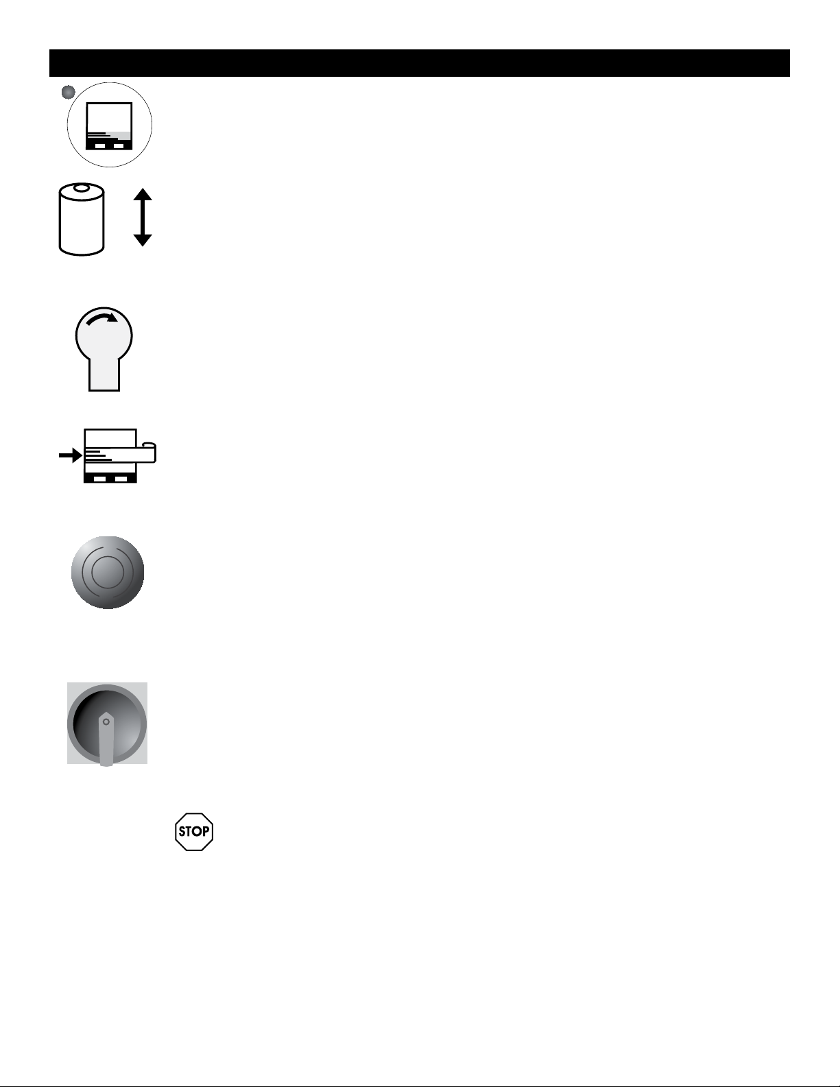
SYSTEM SPECIFICATIONS
MACHINE DIMENSIONS
Length 98"
Width 60"
Height 91"
Turntable Diameter 60"
Turntable Height from Floor 3"
Wrapping Height 80"
Operation Space 98 x 60 x 91"
Maximum Load Size 52 x 52 x 72"
Approximate Shipping Weight 1175 l b s
ELECTRICAL SPECIFICATIONS
•115 VAC, 60 Hz, Single-phase, 15 AMP
TURNTABLE SYSTEM
•20 loads per hour (spiral)
•12 RPM turntable maximum speed
•4,000 lbs turntable maximum load capacity
FILM CARRIAGE/ELEVATOR SYSTEM
•Adjustable raise and lower speeds
•Automatic height detection photoelectric sensor
SCALE
•RS232 Serial Port
FILM DELIVERY SYSTEM
•Infinite / Manual Stretch Adjustment
•10" Diameter Roll Capacity
•20" Roll Width Capacity
CAUTION! Motor control equipment and
electronic controllers are connected to
hazardous line voltages. When servicing
drive and controllers, there may be exposed
components with housings or protrusions at or
above line potential. Extreme care should be
taken to protect against shock.
The user is responsible for conforming to all
applicable code requirements with respect to
grounding requirements. Do NOT use extension
cords to operate the equipment.
Disconnect AC input power before checking
components, performing maintenance,
cleaning up, and when the machine is not in
use. Do NOT connect or disconnect wires and
connectors while power is applied to circuit.
Wiring work should be performed only by
qualified personnel. There is a danger of
electric shock or fire.
WARNING! Loose clothing must NOT be worn
while the machine is in operation. Stay clear
of moving parts while the machine is running.
PAGE 1 OF 33 0913 IH-1619
Page 2
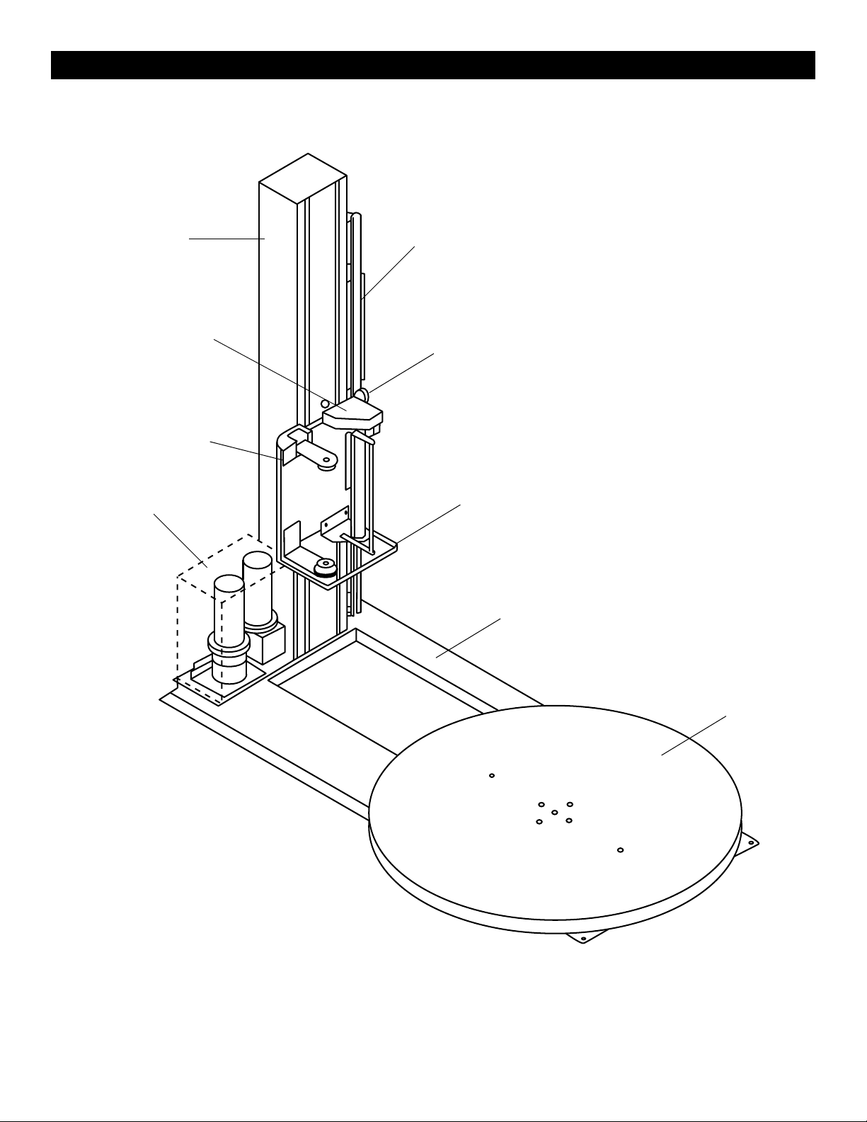
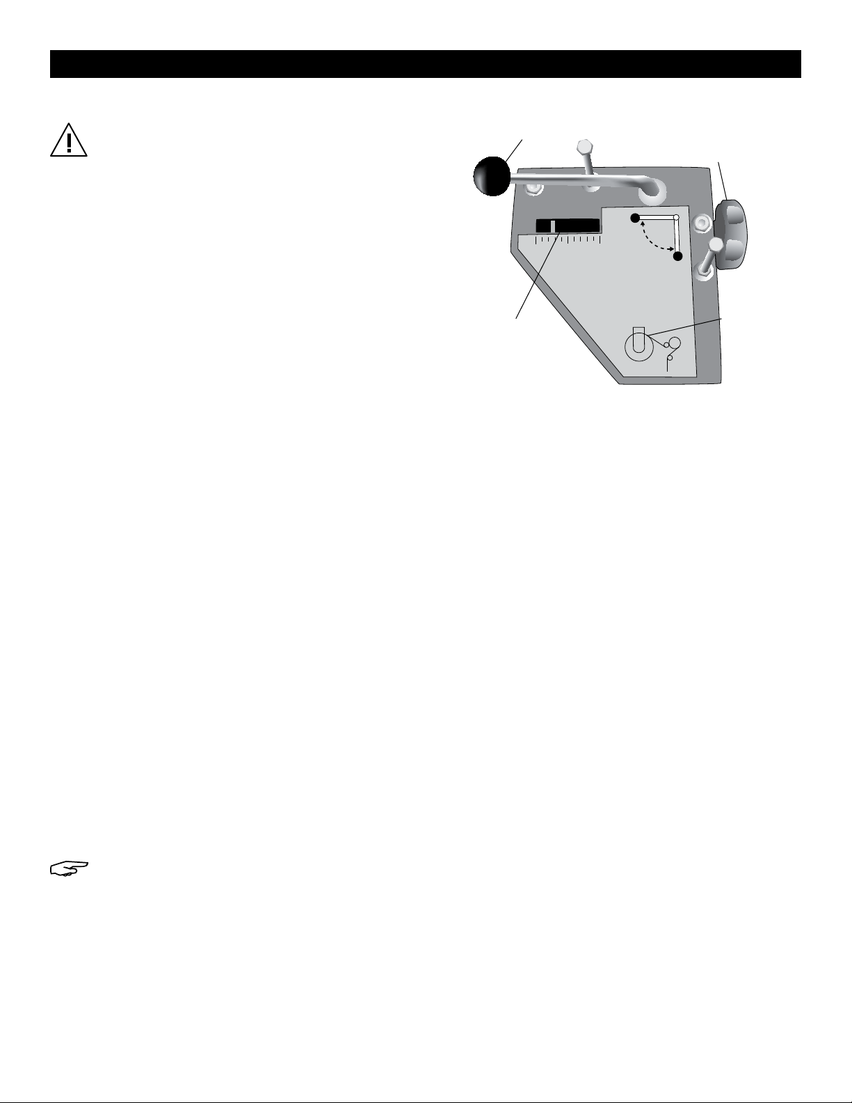
SYSTEM DESCRIPTION
Tower
Stretch Handle
Film Carriage
Motor Box
Control Box
Tension Adjustment Knob
Foot Safety Bar
Seat
Turntable
PAGE 2 OF 33 0913 IH-1619
Page 3
SYSTEM SET-UP
MACHINE PLACEMENT
Place the Automatic Stretch Wrap Machine close to an
area where you will be wrapping your pallet loads. Make
sure that there is sufficient room to load/unload the
machine and that you do not stretch the wiring cable.
Remember, you will need to provide electrical service to
a 120 VAC, 15-AMP outlet.
FLOOR WEIGHT BEARING TOLERANCE
The floor must be able to bear the weight of the
machine, the weight of the maximum load, plus a safety
factor. The floor must also be able to tolerate the stress of
the machine’s operation. If fork trucks will operate on the
same weight bearing area, add the weight of the trucks
to the weight bearing stress tolerance requirements.
MACHINE SET-UP
1. Place skidded machine close to the designated wrap
area. Remove all shipping fasteners holding the
machine to the pallet. The machine may be crated
with the tower tilted down and the motor cover front
carriage roller removed for shipping purpose.
2. Place forks of the forklift through the tubes provided
at the rear base of the module, remove the machine
from skids and place it at the designated wrap area.
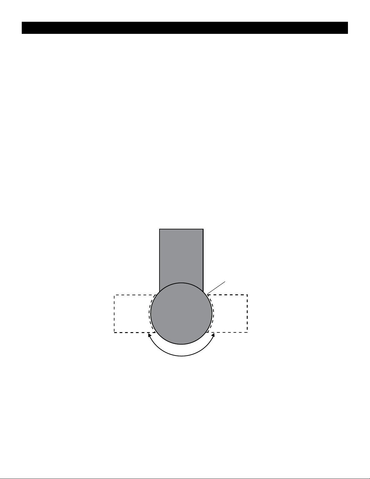
3. If the OPTIONAL ramp (H-1676) is purchased: Select a
ramp position as illustrated below. The ramp can be
positioned anywhere in a 180° rotation around the
front of the turntable. There should be a 1/4" gap
between the turntable and the ramp. The ramp
should be fully supported by the floor. (See Figure 1)
180˚
Figure 1
1/4" Gap
PAGE 3 OF 33 0913 IH-1619
Page 4
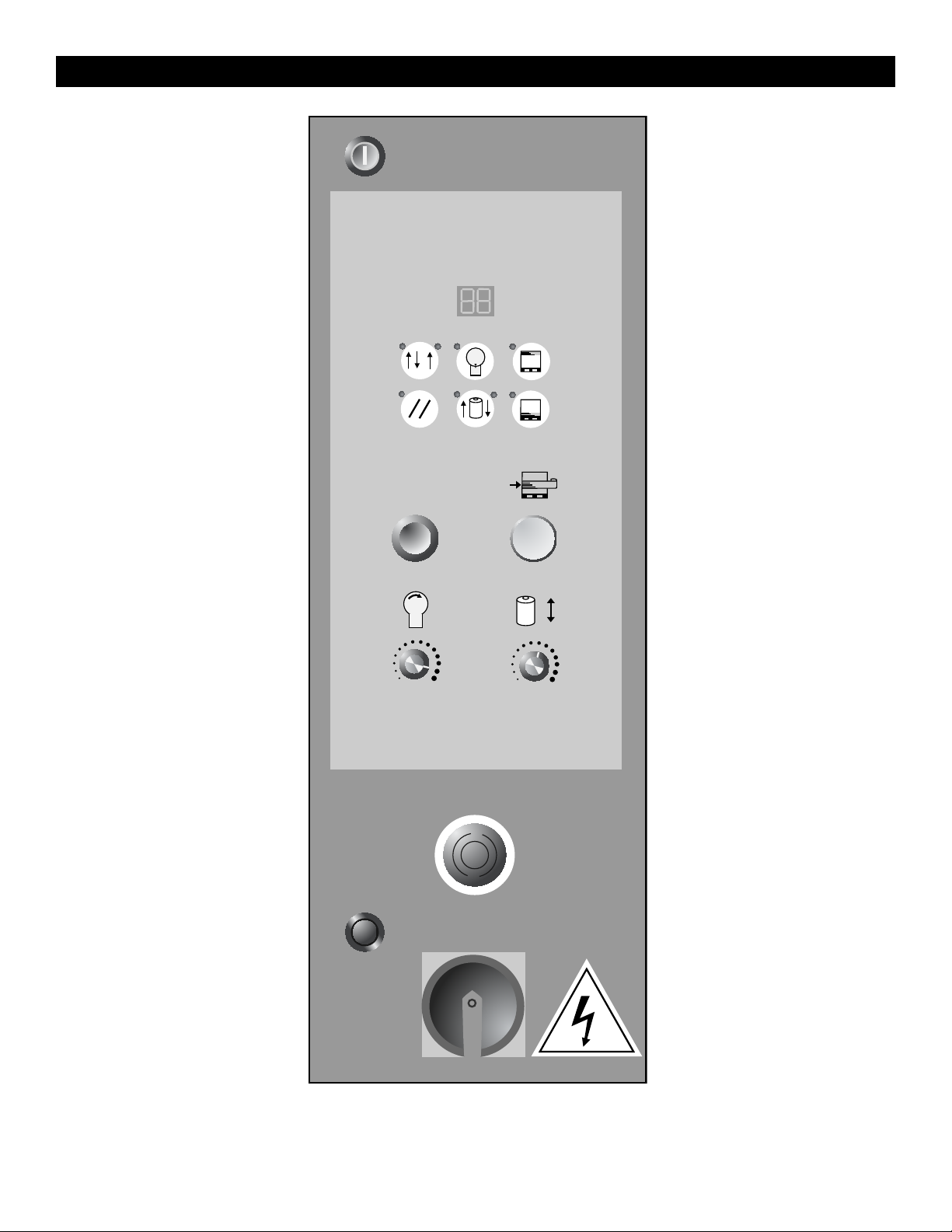
CONTROL BOX
INFO
WRAP
MODES
SYSTEM
RESET
START
TURNTABLE
SPEED
TURNTABLE
JOG
CARRAIGE
JOG
TOP
WRAPS
BOTTOM
WRAPS
BANDING
CARRIAGE
SPEED
PAGE 4 OF 33 0913 IH-1619
Page 5
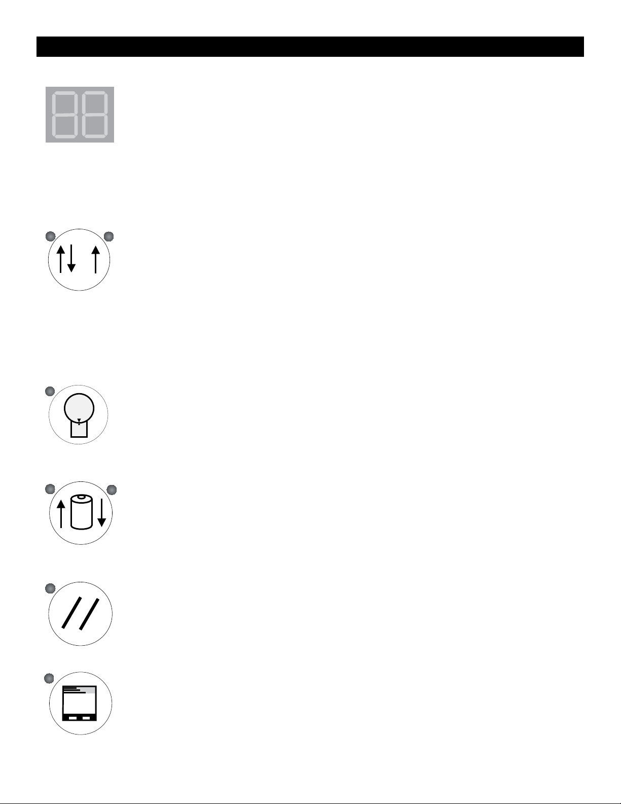
CONTROL BOX CONTINUED
LED DISPLAY
EO Emergency Stop Condition
- - System is normal
A Mode A Selected
B Mode B Selected
CO Continue operation by pushing START button
S System is in Manual
BUTTONS
WRAPPING MODE A - WRAP UP AND DOWN
The LED on the button’s upper left is on. In Mode A, the bottom wrap is applied first, and then the
top wrap follows. The film carriage comes down to its home position after wrapping cycle is
finished.
WRAPPING MODE B - WRAP UP ONLY
The LED on the upper left is on. In Mode B, after a bottom to top wrapping is completed, the
carriage stays on the top. The START button flashes at this point. To resume the operation, push
START. When the carriage reaches the bottom, the START button turns off. Push START button again
to begin a new cycle.
The TURNTABLE JOG button allows you to manually operate the turntable. When this button is
pushed, the light on the button’s upper left is on. Push START button to run the table. Pushing the
button again will stop the turntable and the light will turn off. This button may be used in
conjunction with the CARRIAGE JOG button.
The CARRIAGE JOG button allows you to manually operate the carriage. When this button is
pushed, one of the lights on the button’s upper right or left is on. The upper left light indicates that
the carriage will go up when the START button is pushed. Conversely, the upper right light
indicates the carriage will go down when the START button is pushed. To pause operation, simply
push this button again. Both indicator lights will go off. This button may be used in conjunction
with the TURNTABLE JOG button.
Push this RESET button, followed by the START button, to reset the system. The turntable will return to
its home position and the carriage will lower.
Push the TOP WRAPS button to select the number of top wraps desired (0 - 9).
PAGE 5 OF 33 0913 IH-1619
Page 6
CONTROL BOX CONTINUED
Push the BOTTOM WRAPS button to select the number of bottom wraps desired (0 - 9).
Turn the CARRIAGE SPEED adjustment knob clockwise to increase, and counterclockwise to
decrease the carriage speed. This allows you to adjust the overlap of your film.
Turn the TURNTABLE SPEED adjustment knob clockwise to increase, and counterclockwise to
decrease the turntable speed.
The BANDING button is used for applying multi-layer reinforcing wraps in automatic or manual
mode. Push and hold this button: the carriage will stop raising / lowering. When released, the
carriage will resume its movement.
The EMERGENCY STOP button stops the turntable in the event of emergency. This will NOT stop the
turntable instantly. The turntable will coast to a stop, depending on the load’s weight, after this
button is pushed.
This switches the main power ON or OFF.
WARNING! The FOOT SAFETY BAR, located underneath the film carriage works only when
the machine is ON. When the bar is activated, the main power will shut OFF. Releasing
the bar will reactivate the main power. Push START button to resume the operation.
PAGE 6 OF 33 0913 IH-1619
Page 7
FILM LOADING
Stretch Handle
MACHINE OPERATION
CAUTION! Be sure EMERGENCY STOP is pushed
in before threading the film and pulled out
when the film is threaded.
1. Place the film on the film mandrel.
2. Set the Stretch Handle to the OFF position to release
film tension.
3. Follow the Film Feed Diagram and thread the 6 foot
film tail ALL THE WAY through the rollers.
4. Set the Stretch Handle to the OFF position to release
film tension.
5. Rotate the Stretch Tension Adjustment Knob
clockwise to increase film tension or
counterclockwise to decrease film tension.
6. Attach the film securely to the pallet. Tying the end
of the film in a knot often helps secure the film to
the pallet.
NORMAL SYSTEM START-UP
1. Place the film on the film mandrel.
2. Set the Stretch Handle to the OFF position to release
film tension.
3. Thread the film as instructed and attach it to the
product.
(Off Position)
LESS
Stretch Tension
Indicator
500100
STRETCH
MORE
Stretch Tension
Adjustment Knob
OFF
ON
Film Feed
Diagram
APPLYING REINFORCEMENT WRAPS
1. Press the START button as normal to initiate cycle.
2. As the carriage travels up, press and hold the
BANDING button. The carriage travels up, press and
hold the BANDING button. The carriage will stop
and reinforcing wraps will be applied.
3. Letting go of the BANDING button will resume the
cycle.
4. Set the desired numbers for top and bottom wrap
counts.
5. Select wrapping mode A or B.
6. Press the START button to initiate cycle.
STOP CONDITION
1. In the event of an emergency, press the STOP
button. This cancels the current wrapping cycle and
immediately stops the system.
2. Correct the problem
3. Pull the STOP button out and perform normal system
start-up procedure.
NOTE: After pressing the STOP button, wait for
at least 60 seconds before pulling the button
back out. This will allow the microcontroller
card to completely turn off.
PAGE 7 OF 33 0913 IH-1619
Page 8
SELF-TEST PROCEDURE
A1
A2
An operator may check the status of the machine by
running a self-test. If the procedure is carried out
properly, the INFO screen will display the location of the
problem(s).
To run the self-test, follow the procedure below:
1. Turn the turntable and carriage speed adjustment
knobs to maximum (clockwise) position.
2. Put a load on the turntable (about 3 feet tall).
3. While holding down the TURNTABLE JOG and
CARRIAGE JOG buttons, turn the main disconnect
switch ON.
4. Release the buttons after the screen shows “EE”.
5. Push the START button. The machine will run the test,
which takes approximately 2 minutes.
6. The screen will display the alarm code. Refer to the
table below for code information.
DISPLAY POSSIBLE PROBLEM LOCATION(S)
A1 Film carriage Safety Bar
EMERGENCY STOP button
Electrical enclosure safety switch
B1 Film carriage max upper limit switch
C1 Film carriage max down limit switch
D1 Turntable count/home proximity switch
E1 BANDING push button
F1 START push button
G1 Package height photo sensor
A2 START light
B2 Turntable motor
C2 Carriage motor
F1
E1
G1
D1
B1
C1
B2
C2
PAGE 8 OF 33 0913 IH-1619
Page 9
CALIBRACIÓN/FUNCIONAMIENTO DE LA BÁSCULASCALE CALIBRATION/OPERATION
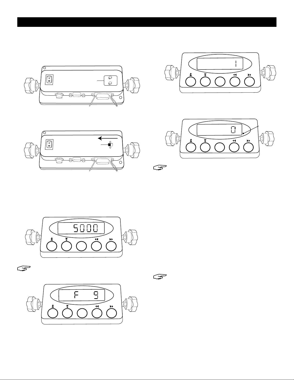
SCALE CALIBRATION/OPERATION
1. Turn power off. Remove ‘X1’ plate from bottom of
display to expose calibration switch. (See Figure 2)
Figure 2
Placa X1
2. Slide calibration switch towards off/on switch to enter
calibration mode. (See Figure 3)
Figure 3
Calibration Switch
•Set value to ‘1’. Press NET/GROSS to save.
Press UNITS to exit. (See Figure 6)
Figure 6
SET
UNITS
NET
GROSS
PRINTTAREZERO
•Press PRINT to scroll to ‘F10’. Press ZERO and verify that
value is ‘0’. Press NET/GROSS to save. Press UNITS to exit.
(See Figure 7)
Figure 7
Green Light
SET
UNITS
NET
GROSS
PRINTTAREZERO
NOTE: If screen does not show ‘5,000’ press
UNITS or ZERO buttons.
3. Turn power on. Display should read ‘F1’.
4. TO SET 5,000 LB. SCALE:
•Press ZERO and verify that screen shows ‘5,000’.
Press SET. Press UNITS. (See Figure 4)
SET
UNITS
NET
GROSS
PRINTTAREZERO
NOTE: If screen does not show ‘5,000,’ press
UNITS or ZERO buttons.
SET
UNITS
NET
GROSS
PRINTTAREZERO
Figure 4
Figure 5
5. TO STABILIZE SCALE:
•Remove any items from scale.
•Use PRINT or TARE to scroll to ‘F16’.
•Press ZERO.
•When stabilized, green light will appear.
(See Figure 7)
•Press ZERO. Press NET/GROSS. Screen will return to ‘F16’.
6. TO CALIBRATE SPAN:
•Using PRINT or TARE, scroll to ‘F17’. Press ZERO to enter
Span Calibration Menu.
•Use PRINT, TARE and ZERO to enter test weight (must be
at least 10% of scale capacity).
NOTE: PRINT and TARE move digit left or right.
UNITS and ZERO changes flashing digit.
•Place test weight on scale and allow unit to stabilize for
at least 30 seconds. Press NET/GROSS to return to ‘F17’.
•Do not remove weight. Slide calibration switch on
back to original position. Meter will count down and
read test weight on screen.
•Reinstall ‘X1’ plate.
•Press PRINT or TARE and scroll to F9. Press ZERO.
•Scale is now calibrated and ready for use.
(See Figure 5)
PAGE 9 OF 33 0913 IH-1619
Page 10

RECOMMENDED SCALE CONFIGURATION VALUES
NOTE: Changing the scale parameters to values other than the recommended values may result in poor
scale operation.
NAME/CODE DESCRIPTION RECOMMENDED
VALUE
F1: GRADUATIONS Specifies the number of full-scale graduations. Value should be consistent with legal
requirements and environmental limits on the useful system resolution.
F2: SPAN GAIN Span Gain is related to A/D integration time. The larger the span gain, the higher the internal
resolution, but the slower the update speed. Note that the scale must be re-calibrated
whenever this parameter is altered. See Appendix C in the scales manual for more information.
F3: ZERO TRACK BAND Selects the range within which the scale will automatically zero. Note that the scale must be in
a standstill to zero the scale.
F4: ZERO RANGE Selects the range within which the scale may be zeroed. Note that the indicator must be in
standstill to zero the scale.
F5: MOTION BAND Sets the level at which motion is detected by comparing the present display update with the
previous one. If motion is not detected for two seconds or more, scale is in standstill and can
process a Print or Zero command. Maximum value varies depending on local regulations.
F6: DIGITAL FILTER Averages weight readings to produce higher stability but slower the indicator’s response time.
Choose 8 unless a very fast response is needed.
F7: OVERLOAD LIMIT Selects the desired formula which determines the point at which the indicator shows overload.
All selections are based on the primary unit selected in F8.
F8: CALIBRATION UNIT Selects the primary base unit to be used in the calibration process. Also the default unit for
normal operation. 1 = pounds, 2 = kilograms.
F9: DISPLAY DIVISIONS Determines the desired weight increments. Value should be consistent with legal requirements. 1
F10: DECIMAL POINT Determines the location of the decimal point. 0
F16: ZERO CALIBRATION Places the scale in a Zero Calibration routine. —
F17: SPAN CALIBRATION Places the scale in a Span Calibration routine. —
5000
100
100
2%
3
1
8
1
PAGE 10 OF 33 0913 IH-1619
Page 11

TROUBLESHOOTING
WARNING! Make sure that only qualified
personnel perform inspection, troubleshooting
and part replacement.
CAUTION! Disconnect all power, including
external control power that may be present,
before servicing the frequency drive
controllers. WAIT for three (3) minutes for
the DC bus capacitors to discharge. The
frequency drive controller’s display and/or LEDs
are not accurate indicators of the absence of
DC bus voltage.
OPERATING ISSUE CAUSES RECOMMENDATIONS
Machine not powering on.
Main power is turned off. Check that power is going to the scale. Verify that switch is
turned on.
Machine not plugged into 120VAC outlet. Verify the voltage going to the scale matches the power
supply labels on the power module or scale.
Power supply faulty.
Internal battery not charged.
Film carriage foot engaged. Remove obstruction from Film Carriage foot.
Film carriage malfunctioning.
Turntable is malfunctioning.
FILM CARRIAGE SPEED dial not set high
enough.
Resistance of potentiometer not equal to
5K_ across.
The carriage limit switch lever arm is
obstructed.
Microcontroller card inside electrical
enclosure not turned on.
Turntable speed potentiometer dial not
set high enough.
Resistance of potentiometer not equal to
5K_ across.
Microcontroller card inside electrical
enclosure not turned on.
The turntable motor is not running. Tighten or replace motor wiring as necessary.
Adjust potentiometer towards 100% to set speed.
Tighten wiring, replace dial if necessary.
Remove obstruction and/or clean limit switch head.
Check and switch on the main circuit breaker.
Adjust potentiometer towards 100% to set speed.
Tighten wiring, replace dial if necessary.
Check and switch on main circuit breaker.
Check turntable for mechanical restrictions.
Replace microcontroller or turntable output relav.
π
CHICAGO•ATLANTA•DALLAS•LOSANGELES•MINNEAPOLIS•NYC/PHILA•SEATTLE•MEXICO•CANADA
1-800-295 -5510
PAGE 11 OF 33 0913 IH-1619
uline.com
Page 12

π H-1619
DESPACHADORA
AUTOMÁTICA DE PELÍCULA
ELÁSTICA CON BÁSCULA
ESPECIFICACIONES DEL SISTEMA
01-800-295-5510
uline.mx
DIMENSIONS DE LA MACHINE
Largo 98"
Ancho 60"
Altura 91"
Diámetro de Plataforma Giratoria 60"
Altura de Plataforma Giratoria desde el Piso 3"
Altura para Envolver 80"
Espacio de Funcionamiento 98 x 60 x 91"
Tamaño Máximo de Carga 52 x 52 x 72"
Peso Aproximado del Envío 1175 l b s
ESPECIFICACIONES ELÉCTRICAS
•115 VAC, 60 Hz, Monofásica, 15 AMP
SISTEMA DE PLATAFORMA GIRATORIA
•20 cargas por hora (espiral)
•12 RPM de velocidad máxima de plataforma giratoria
•4,000 lbs. de capacidad máxima de plataforma
giratoria
SISTEMA DEL PORTADOR DE PELÍCULA/ELEVADOR
•Velocidades ajustables para elevación y descenso
•Sensor fotoeléctrico automático para detección de
altura
BÁSCULA
•Puerto Serial RS232
SISTEMA PARA DESPACHAR LA PELÍCULA
•Ajuste de Película Infinito / Manual
•Capacidad del Rollo de 10” de Diámetro
•Capacidad del Rollo de 20” de Ancho
¡PRECAUCIÓN! El equipo de control del motor y
los reguladores están conectados a líneas de
voltaje peligrosas. Cuando dé mantenimiento
a la unidad y reguladores, los componentes
pueden estar expuestos a cubiertas o salientes
en o por encima de la línea de voltaje. Deberá
tomar precauciones extremas para protegerse
contra choque eléctrico.
El usuario es responsable de cumplir con todos
los códigos de los reglamentos aplicables con
respecto a los requerimientos para conexión a
tierra. NO use extensiones eléctricas para operar
el equipo.
Desconecte la alimentación de la corriente
directa antes de revisar los componentes, dar
mantenimiento, limpiar, y cuando la máquina
no esté en uso. NO conecte o desconecte
cables y conectores mientras se suministra
energía al circuito.
El cableado debe ser realizado solo por personal
calificado. Existe el peligro de choque eléctrico
o incendio
¡ADVERTENCIA! NO debe usar ropa floja mientras
la máquina esté funcionando. Manténgase
alejado de partes móviles mientras la máquina
está operando.
PAGE 12 OF 33 0913 IH-1619
Page 13

DESCRIPCIÓN DEL SISTEMA
Torre
Portador de Películ
Portador de Películ
Caja del Motor
Caja de Control
Perilla para Ajuste de Tensión
Pedal de Seguridad
Soporte
Plataforma Giratoria
PAGE 13 OF 33 0913 IH-1619
Page 14

CONFIGURACIÓN DEL SISTEMA
COLOCACIÓN DE LA MÁQUINA
Coloque la Máquina Automática para Película Elástica
cerca del área donde esté envolviendo sus tarimas de
carga. Asegúrese que hay suficiente espacio para
cargar/descargar la máquina y que no se estire el
cable de conexión. Recuerde, necesita tener servicio
para una toma de corriente de 120 VAC, 15-AMP.
RESISTENCIA DEL PISO PARA SOSTENER EL PESO
El piso deberá tener la capacidad de sostener el peso
de la máquina, la carga de mayor peso, además del
factor de seguridad. El piso debe también resistir la
presión del funcionamiento de la máquina. Si se
manejarán montacargas en la misma área de soporte
de peso, agregue el peso de los montacargas a los
INSTALACIÓN DE LA MÁQUINA
1. Coloque la máquina entarimada cerca del área
designada para envoltura. Retire todos los cinchos
que fijan la máquina a la tarima. La máquina puede
haberse empacado con la torre hacia abajo y sin la
cubierta frontal del rodillo portador para propósitos
de envío.
2. Inserte las horquillas del montacargas a través de
los tubos ubicados en la base posterior del módulo,
retire la máquina de las tarimas y colóquela en el
área designada para envoltura.
3. Si compra la rampa OPCIONAL (H-1676): Seleccione
una posición para la rampa como se ilustra abajo.
La rampa puede ser posicionada en cualquier lugar
en una rotación a 180° alrededor del frente de la
plataforma giratoria. Debe haber una separación
de ¼” entre la plataforma giratoria y la rampa. La
rampa deber estar completamente apoyada en el
piso. (Vea Diagrama 1)
180˚
Diagrama 1
Separación
de 1/4"
PAGE 14 OF 33 0913 IH-1619
Page 15

CAJA DE CONTROL
INFORMACIÓN
MODOS DE
ENVOLTURA
REINICIO
AL SISTEMA
INICIO
VELOCIDAD
DE PLATAFORMA
GIRATORIA
IMPULSO DE
PLATAFORMA
GIRATORIA
IMPULSO DEL
PORTADOR
ENVOLTURA
SUPERIOR
ENVOLTURA
INFERIOR
ATAR CON BANDA
VELOCIDAD
DEL PORTADOR
PAGE 15 OF 33 0913 IH-1619
Page 16

CONTINUACIÓN DE CAJA DE CONTROL
PANTALLA LED
EO Parada por Situación de Emergencia
- - Sistema normal
A Modo A Seleccionado
B Modo B Seleccionado
CO Funcionamiento Continuo al presionar el botón START
S Sistema en Manual
BOTONES
ENVOLTURA EN MODO A – ENVOLTURA POR ARRIBA Y ABAJO
El LED de la parte izquierda superior del botón está encendido. En Modo A, la envoltura se
aplica primero en la parte inferior, y después sigue la envoltura superior. El portador de la
película baja a su posición de inicio después de terminar el ciclo de envoltura.
ENVOLTURA EN MODO B – ENVOLTURA POR ARRIBA SOLAMENTE
El LED en la parte izquierda superior está encendido. En Modo B, después de que la envoltura
desde abajo hasta arriba está completa, el portador permanece en la parte superior. El botón
START parpadea en este punto. Para reiniciar el funcionamiento, presione START. Cuando el
portador llega a la parte inferior, el botón START se apaga. Presione el botón START de nuevo y
empiece el nuevo ciclo.
El botón TURNTABLE JOG le permite operar manualmente la plataforma giratoria. Cuando este
botón es presionado, la luz en la parte izquierda superior del botón se enciende. Presione el
botón START para poner a funcionar la plataforma. Al presionar de nuevo el botón detendrá la
plataforma giratoria y la luz se apagará. Este botón puede utilizarse en conjunto con el botón de
CARRIAGE JOG.
El botón CARRIAGE JOG permite operar manualmente el portador. Cuando este botón es
presionado, una de las luces en la parte superior derecha del botón se enciende. La luz superior
izquierda indica que el portador irá hacia arriba cuando el botón START es presionado. Por el
contrario, la luz superior derecha indica que el portador irá hacia abajo cuando el botón START
es presionado. Para pausar la función simplemente presione este botón de nuevo. Ambas luces
indicadoras se apagarán. Este botón puede utilizarse en conjunto con el botón TURNTABLE JOG.
Presione este botón RESET, seguido por el botón START, para reiniciar el sistema. La plataforma
giratoria regresará a su posición de inicio y el portador bajará.
Presione el botón TOP WRAPS para seleccionar el número de envolturas en la parte superior (0-9).
PAGE 16 OF 33 0913 IH-1619
Page 17

CONTINUACIÓN DE CAJA DE CONTROL
Presione el botón BOTTOM WRAPS para seleccionar el número de envolturas deseadas en parte
inferior (0-9).
Gire la perilla de ajuste CARRIAGE SPEED en el sentido de las manecillas del reloj para
incrementar, y al contrario de las manecillas del reloj para disminuir la velocidad del portador.
Esto le permite ajustar la superposición de su película.
Gire la perilla de ajuste TURNTABLE SPEED en el sentido de las manecillas del reloj para
incrementar, y al contrario de las manecillas del reloj para disminuir la velocidad de la
plataforma giratoria.
El botón BANDING es utilizado para aplicar multicapas para reforzar la envoltura en modo
automático o manual. Presione y sostenga este botón: el portador detendrá de subir/ bajar.
Cuando lo libere, el portador reanudará su movimiento.
El botón EMERGENCY STOP detiene la plataforma giratoria en situación de emergencia. Esto NO
detendrá la plataforma giratoria instantáneamente. La plataforma giratoria se detendrá por
inercia, dependiendo del peso de la carga, después de que el botón sea presionado.
Este cambia el interruptor principal a Encendido o Apagado. (Enciende y Apaga el interruptor
principal).
¡PRECAUCIÓN! El PEDAL DE SEGURIDAD, localizado debajo del portador de la película,
trabaja solo cuando la máquina está Encendida. Cuando la barra es activada, la
corriente principal se apagará. Al liberar el pedal reactivará la corriente principal.
Presione el botón START para reiniciar el funcionamiento.
PAGE 17 OF 33 0913 IH -1619
Page 18

FUNCIONAMIENTO DE LA MÁQUINA
Asa para Película
CARGAR LA PELÍCULA
¡PRECAUCIÓN! Asegúrese de presionar el
BOTÓN DE EMERGENCIA antes de cargar la
película y sea presionado de nuevo para
liberar cuando la película está cargada.
1. Coloque la película en el mandril de la película.
2. Mueva la Asa de la Película a la posición OFF para
liberar la tensión de la película.
3. Siga el Diagrama de Alimentación de la Película y
cargue los 6 pies (1.80M) de película TODO EL
TRAYECTO a través de los rodillos.
4. Mueva la Asa de la Película a la posición OFF para
liberar la tensión de la película.
5. Gire la Perilla de Ajuste de Tensión de Película en el
sentido de las manecillas del reloj para aumentar
la tensión de la película o en el sentido contrario a
las manecillas del reloj para disminuir la tensión.
(Posición Apagado)
LESS
STRETCH
Indicador de
Tensión de Película
MORE
500100
Perilla de Ajuste de
Tensión de Película
OFF
ON
APLICAR ENVOLTURAS DE REFUERZO
Diagrama de
Alimentación
de Película
6. Sujete la película a la tarima de manera segura.
Anudando el extremo de la película ayuda con
frecuencia a asegurar la tarima.
ARRANQUE NORMAL DEL SISTEMA
1. Coloque la película en el mandril de la película.
2. Mueva la Asa de la Película a la posición OFF para
liberar la tensión de la película.
3. Coloque la película como se indica y sujétela en el
producto.
4. Configure los números deseados para el conteo de
envolturas superior e inferior.
5. Seleccione el modo de envoltura A o B.
6. Presione el botón de START para iniciar el ciclo.
SITUACIÓN DE PARO
1. En una situación de emergencia, presione el botón
STOP. Esto cancela el ciclo de envoltura actual e
inmediatamente detiene el sistema.
2. Corrija el problema.
1. Presione el botón START de manera normal para
iniciar el ciclo.
2. Mientras el portador se mueve hacia arriba,
presione y sostenga el botón BANDING. El portador
hace alto y las envolturas de refuerzo serán
aplicadas.
3. Liberando el botón BANDING se reanudará el ciclo.
3. Jale el botón STOP y siga el procedimiento de
arranque normal del sistema.
NOTA: Después de presionar el botón STOP,
espere al menos 60 segundos antes de jalar el
botón de regreso. Esto permitirá que la tarjeta
del microcontrolador se apague
completamente.
PAGE 18 OF 33 0913 IH-1619
Page 19

PROCEDIMIENTO DE AUTOPRUEBA
A1
A2
Un operador puede revisar el estado de la máquina
corriendo la autoprueba. Si el procedimiento se lleva a
cabo correctamente, la pantalla de INFO mostrará la
ubicación del (los) problema(s).
Para correr la autoprueba, siga el procedimiento de
abajo:
1. Gire las perillas de ajuste de la plataforma giratoria
y el portador a la posición máxima (al sentido de
las manecillas del reloj).
2. Coloque una carga en la plataforma giratoria
(cerca de 3 pies de alto).
3. Mientras mantiene presionados los botones
TURNTABLE JOG y CARRIAGE JOG, encienda el
interruptor de desconexión principal.
4. Libere los botones después que la pantalla muestra
“EE”.
5. Presione el botón START. La máquina correrá la
prueba, la cual toma aproximadamente 2 minutos.
6. La pantalla mostrará el código de alarma.
Consulte la tabla abajo para información de
códigos.
PANTALLA POSIBLE UBICACIÓN DE PROBLEMA(S)
A1 Barra de Seguridad del portador de película.
Botón EMERGENCY STOP
Interruptor de seguridad de la caja eléctrica
B1 Interruptor de límite máx superior del portador de
película
C1 Interruptor de límite máx inferior del portador de
película
D1 Interruptor de conteo de plataforma giratoria/
proximidad al inicio
E1 Botón de presión BANDING
F1 Botón de presión START
G1 Foto sensor de altura del paquete
A2 Luz START
B2 Motor de la plataforma giratoria
C2 Motor del portador
F1
B1
B2
G1
E1
C1
C2
D1
PAGE 19 OF 33 0913 IH-1619
Page 20

CALIBRACIÓN/FUNCIONAMIENTO DE LA BÁSCULA
CALIBRACIÓN/FUNCIONAMIENTO DE LA BÁSCULA
CALIBRACIÓN/FUNCIONAMIENTO DE LA BÁSCULA
1. Apague la unidad. Retire la placa ’X1´ de la base
de la pantalla para exponer el interruptor de
calibración. (Vea Diagrama 2)
Diagrama 2
X1 Plate
2. Deslice el interruptor de calibración hacia el
interruptor de apagado/encendido para acceder
al modo de calibración. (Vea Diagrama 3)
Diagrama 3
Interruptor
de Calibración
•Configure el valor a ´1´. Presione NET/GROSS para
grabar. Presione UNITS para salir. (Vea Diagrama 6)
Diagrama 6
SET
UNITS
NET
GROSS
PRINTTAREZERO
•Presione PRINT para desplazarse a ´F10´. Presione
ZERO y verifique que el valor es ´0´. Presione NET/
GROSS para grabar. Presione UNITS para salir.
(Vea Diagrama 7)
UNITS
SET
NET
GROSS
Diagrama 7
Green Light
PRINTTAREZERO
NOTA: Si la pantalla no muestra ´5,000´,
presione los botones UNITS o ZERO.
3. Encienda la unidad. En la pantalla debe leerse ‘F1´.
4. CONFIGURAR LA BÁSCULA DE 5,000 LBS.:
•Presione ZERO y verifique que la pantalla muestre
´5,000´. Presione SET. Presione UNITS. (Vea Diagrama 4)
Diagrama 4
SET
UNITS
NET
GROSS
PRINTTAREZERO
NOTA: Si la pantalla no muestra ´5,000´,
presione los botones UNITS o ZERO.
•Presione PRINT o TARE y desplace hacia F9. Presione
ZERO. (Vea Diagrama 5)
Diagrama 5
SET
UNITS
NET
GROSS
PRINTTAREZERO
5. ESTABILICE LA BÁSCULA:
•Retire cualquier artículo de la báscula.
•Utilice PRINT o TARE para desplazarse a ´F16¨.
•Presione ZERO. Cuando se estabilice, una luz verde
aparecerá. (Vea Diagrama 7)
•Presione ZERO. Presione NET/GROSS. La pantalla
regresará a ´F16´.
6. CALIBRE LOS VALORES:
•Utilizando PRINT o TARE, desplácese a ´F17´. Presione
ZERO para acceder el Menú de Calibración de
Valores.
•Utilice PRINT, TARE y ZERO para acceder el peso de
prueba (debe ser al menos 10% de la capacidad
de la báscula).
NOTA: PRINT y TARE mueven los dígitos a la
izquierda o derecha. UNITS y ZERO cambian
el dígito intermitente.
•Coloque las pesas de prueba sobre la báscula y
permita a la unidad estabilizarse por al menos 30
segundos. Presione NET/GROSS para regresar a ´F17´.
•·No retire el peso. Deslice el interruptor de calibración
de regreso a su posición original. El contador hará
una cuenta regresiva y se leerá el peso de prueba en
pantalla.
•·Reinstale la placa ´X1´.
•·La báscula queda calibrada y lista para utilizarse.
PAGE 20 OF 33 0913 IH-1619
Page 21

RECOMMENDED SCALE CONFIGURATION VALUES
NOTA: Cambiar los valores de los parámetros de la báscula a otros a valores diferentes a los
recomendados puede resultar en un funcionamiento deficiente de la báscula.
VALOR
NOMBRE/CÓDIGO DESCRIPCIÓN
F1: GRADUACIONES Especifica el número de la escala completa de graduaciones. El valor debe ser
consistente con los requerimientos legales y los límites ambientales sobre el uso de la
resolución del sistema.
F2: AUMENTO DEL LAPSO Span Gain está relacionado con la integración del tiempo de A/D. Mientras más se
aumente el lapso, más alta será la resolución, pero más lenta la actualización de la
velocidad. Note que la báscula debe ser calibrada de nuevo cuando este parámetro
sea alterado. Vea Apéndice C en las básculas manuales para más información.
F3: BANDA DE PISTA EN CERO Selecciona el rango dentro del cual la báscula se pondrá en cero automáticamente.
Note que la báscula debe estar en punto muerto para ponerse en cero.
F4: RANGO CERO Selecciona el rango dentro del cual la báscula puede ser puesta en cero. Note que el
indicador debe estar en punto muerto para poner la báscula en cero.
F5: BANDA DE MOVIMIENTO Configura el nivel en el cual el movimiento es detectado para comparar la actualización
de la pantalla actual con la previa. Si no se detecta movimiento en dos segundos o más,
la báscula queda en punto muerto y puede procesar el comando Print o Zero. El valor
máximo varía dependiendo de las regulaciones locales.
F6: FILTRO DIGITAL Promedia las lecturas de peso para lograr la máxima estabilidad pero un tiempo de respuesta
más lento del indicador. Elija 8 a menos que requiera de una mayor velocidad de respuesta.
F7: LÍMITE DE SOBRECARGA Selecciona la fórmula deseada que determina el punto en el cual el indicador muestra
sobrecarga. Todas las selecciones están basadas en la unidad principal seleccionada en F8.
F8: UNIDAD DE CALIBRACIÓN Selecciona la base de unidad principal para ser utilizada en el proceso de calibración.
También la unidad predeterminada para la operación normal. 1 = libras, 2 = kilogramos.
F9: DIVISIONES DE PANTALLA Determina los incrementos de peso deseados. El valor debe ser consistente con los
requerimientos legales.
F10: PUNTO DECIMAL Determina la ubicación del punto decimal. 0
F16: CALIBRACIÓN A CERO Coloca la báscula en una rutina de Zero Calibration. —
F17: CALIBRACIÓN DE LAPSO Coloca la báscula en una rutina de Span Calibration. —
RECOMENDADO
5000
100
100
2%
3
1
8
1
1
PAGE 21 OF 33 0913 IH-1619
Page 22

SOLUCIÓN DE PROBLEMAS
¡ADVERTENCIA! Asegúrese de que solo
personal calificado lleve a cabo la
inspección, solución de problemas y
reemplazo de partes.
PROBLEMA DE
FUNCIONAMIENTO
La máquina no enciende.
Falla del portador de película.
¡PRECAUCIÓN! Desconecte toda la corriente,
incluyendo el control externo de corriente
que pudiera estar presente, antes de dar
servicio a los controladores de frecuencia de
dirección. ESPERE por tres (3) minutos para que
los capacitores del bus DC se descarguen. La
pantalla de los controladores de frecuencia
de dirección y/o LEDs no son adecuados para
indicar ausencia de voltaje del bus DC.
CAUSAS RECOMENDACIONES
La corriente principal está apagada. Revise que la corriente llegue a la máquina.
Máquina no está enchufada a una salida de 120VAC. Verifique que el voltaje que llega a la
Falla del suministro de corriente.
Batería interna no está cargada.
El pedal del portador de película está obstruido. Remove obstruction from Film Carriage foot.
Perilla de CARRIAGE SPEED de la película no se
configuró suficientemente alto.
Verifique que el interruptor esté encendido.
máquina coincide con las etiquetas del
suministro de corriente en el módulo de
corriente.
Ajuste el potenciómetro hacia el 100% para
establecer la velocidad.
Falla de la plataforma
giratoria.
La resistencia del potenciómetro no es igual a través
de 5k.
El brazo nivelador del interruptor de límite del
portador está obstruido.
La tarjeta del microcontrolador dentro de la caja
eléctrica no encendió
La velocidad de la perilla del potenciómetro
de la plataforma giratoria no se estableció lo
suficientemente alto.
La resistencia del potenciómetro no es igual a través
de 5K_.
La tarjeta del microcontrolador dentro de la caja
eléctrica no encendió.
El motor de la plataforma giratoria no está corriendo. Ajuste o reemplace el cableado del motor
Ajuste el cableado, reemplace la perilla si es
necesario.
Retire la obstrucción y/o limpie el cabezal del
interruptor de límite.
Revise y encienda el interruptor de circuito
principal.
Ajustar el potenciómetro hacia el 100% para
establecer la velocidad
Ajuste el cableado, reemplace la perilla si es
necesario.
Revise y encienda el interruptor de circuito
principal.
como se requiera.
Revise la plataforma giratoria de limitaciones
mecánicas.
Reemplace el microcontrolador o el relevador
de la plataforma giratoria.
π
CHICAGO•ATLANTA•DALLAS•LOSANGELES•MINNEAPOLIS•NYC/PHILA•SEATTLE•MEXICO•CANADA
01-800-295 -5510
PAGE 22 OF 33 0913 IH-1619
uline.mx
Page 23

π H-1619
DISTRIBUTEUR DE FILM
ÉTIRABLE AUTOMATIQUE
AVEC BALANCE
SPÉCIFICATIONS DU SYSTÈME
1-800-295-5510
uline.ca
DIMENSIONS DE LA MACHINE
Longueur 98po (249cm)
Largeur 60po (152cm)
Hauteur 91po (231cm)
Diamètre de la plaque tournante 60po (152cm)
Hauteur de la plaque du sol 3po (8cm)
Hauteur du banderolage 80po (203cm)
Espace de fonctionnement 98x60x91po
(249x152x231cm)
Taille maximale de la charge 52x52x72po
(132x132x183cm)
Poids d’expédition approximatif 1175lb (533kg)
SPÉCIFICATIONS ÉLECTRIQUES
115V c.a., 60Hz, monophasé, 15A
SYSTÈME DE LA PLAQUE TOURNANTE
20charges par heure (spirale)
Vitesse maximale de la plaque tournante: 12tr/
min
Capacité de charge maximale de la plaque
tournante: 4000lb (1,8T)
CHARIOT PORTE-FILM/SYSTÈME D’ASCENSEUR
Vitesses d’ascension et de descente réglables
Détecteur à cellule photoélectrique de mesure
de hauteur automatique
BALANCE
Port série RS232
SYSTÈME DE DISTRIBUTION DE FILMS
Réglage continu/manuel de l’allongement
Capacité d’enroulement de 10po (25cm) de
diamètre
Capacité d’enroulement de 20po (50cm) de
largeur
MISE EN GARDE! La commande des moteurs et
les régulateurs électroniques sont branchés à
des tensions dangereuses. Lors de l’entretien
du disque et des régulateurs, des pièces
accessibles avec boîtiers ou saillies peuvent
se trouver au niveau ou au-dessus du potentiel
d’une phase. Faites preuve d’extrême
prudence afin d’assurer une protection contre
les chocs.
L’utilisateur est tenu responsable du respect de
toutes les exigences applicables du code et
des exigences de la mise à la terre. N’utilisez
PAS de rallonges pour utiliser l’équipement.
Coupez l’alimentation d’entrée en c.a. avant
la vérification des pièces, toute opération
d’entretien ou de nettoyage et lorsque la
machine n’est pas en service. NE branchez ou
débranchez PAS les câbles et les connecteurs
tant que le circuit est sous tension.
Seul un personnel qualifié peut effectuer
les travaux de câblage. Il existe un risque
d’électrocution ou d’incendie.
AVERTISSEMENT! NE portez PAS de vêtements
ARRÊT
amples lorsque la machine est en marche.
Tenez-vous à l’écart des pièces mobiles
lorsque la machine fonctionne.
PAGE 23 OF 33 0913 IH-1619
Page 24

SYSTEM DESCRIPTION
Tour
Poignée d’allongement
Chariot porte-film
Boîte à moteur
Boîte de commande
Bouton de réglage de tension
Barre de sécurité pour pied
Siège
Plaque tournante
PAGE 24 OF 33 0913 IH-1619
Page 25

INSTALLATION DU SYSTÈME
EMPLACEMENT DE LA MACHINE
Placez la machine d’emballage sous film étirable
automatique près d’une zone où vous allez emballer vos
charges palettisées. Vérifiez qu’il y a suffisamment
d’espace pour charger/décharger la machine et que
vous n’étirez pas le câble. Vous devez fournir un service
d’électricité à une prise de 120V c.a., 15A.
TOLÉRANCE DE ROULEMENT SUR POIDS DU
PLANCHER
Le plancher doit pouvoir supporter le poids de la
machine, le poids de la charge maximale et un facteur
de sécurité. Le plancher doit également être en mesure
de tolérer la tension du fonctionnement de la machine.
Si les chariots à fourche fonctionnent sur la même
surface portante, ajoutez le poids des chariots aux
exigences de tolérance de la tension de la surface
portante.
INSTALLATION DE LA MACHINE
1. Placez la machine sur patins près de la zone indiquée
pour le banderolage. Enlevez toutes les attaches
d’expédition qui maintiennent la machine sur la
palette. La machine peut être emballée avec la tour
inclinée vers le bas et le rouleau de transport avant du
couvercle moteur peut être retiré pour l’expédition.
2. Placez les fourches du chariot élévateur dans les
tubes fournis à la base arrière du module, retirez la
machine des patins et placez-la dans la zone
indiquée pour le banderolage.
3. Si vous avez acheté la rampe FACULTATIVE (H-1676):
choisissez une position de la rampe comme illustré
ci-dessous. Vous pouvez placer la rampe partout,
dans une rotation de 180° autour de l’avant de la
plaque tournante. Vous devez laisser un espacement
de 1/4po (0,6cm) entre la plaque et la rampe. La
rampe doit être entièrement soutenue par le
plancher. (Voir figure1)
180˚
Figure 1
1/4" Gap
PAGE 25 OF 33 0913 IH-1619
Page 26

BOÎTE DE COMMANDE
INFO
MODES
D’EMBALLAGE
SYSTÈME
DERÉINITIALISATION
DE LAPLAQUE
CHARIOTMANUEL
DÉMARRER
VITESSE DE LAPLAQUE
TOURNANTE
VITESSE
EMBALLAGES
SUPÉRIEURS
EMBALLAGES
INFÉRIEURS
BANDEROLAGE
VITESSE DUCHARIOT
PAGE 26 OF 33 0913 IH-1619
Page 27

BOÎTE DE COMMANDE SUITE
AFFICHAGE À DEL
EO État d’arrêt d’urgence
- -Le système est normal
A ModeA sélectionné
B ModeB sélectionné
CO Poursuivre l’opération en appuyant sur le bouton START (DÉMARRER)
S Le système est en manuel
BOUTONS
BANDEROLAGE MODEA- ENROULEMENT EN HAUT ET EN BAS
Le voyant DEL dans le coin supérieur gauche du bouton est allumé. En ModeA, l’emballage
commence par la partie inférieure puis se poursuit par la partie supérieure. Le chariot porte-film
revient à sa position initiale à la fin du cycle de banderolage.
BANDEROLAGE MODEB- ENROULEMENT EN HAUT UNIQUEMENT
Le voyant DEL dans le coin supérieur gauche est allumé. En ModeB, à la fin du banderolage de
la partie inférieure vers la partie supérieure, le chariot reste sur la partie supérieure. Le bouton
START (DÉMARRER) clignote à ce stade. Pour reprendre l’utilisation, appuyez sur START (DÉMARRER).
Lorsque le chariot atteint le fond, le bouton START (DÉMARRER) s’éteint. Appuyez de nouveau sur le
bouton START (DÉMARRER) pour lancer un nouveau cycle.
Le bouton TURNTABLE JOG (PLAQUE TOURNANTE MANUELLE) vous permet d’activer manuellement la
plaque tournante. Lorsque vous appuyez sur ce bouton, le voyant dans le coin supérieur gauche
du bouton s’allume. Appuyez sur le bouton START (DÉMARRER) pour activer la plaque. Si vous
appuyez de nouveau sur le bouton, la plaque tournante s’arrête et le voyant s’éteint. Ce bouton
peut être utilisé avec le bouton CARRIAGE JOG (CHARIOT MANUEL).
Le bouton CARRIAGE JOG (CHARIOT MANUEL) vous permet d’activer manuellement le chariot. Lorsque
vous appuyez sur ce bouton, l’un des voyants dans le coin supérieur droit ou gauche du bouton
s’allume. Le voyant dans le coin supérieur gauche indique que le chariot remonte lorsque vous
appuyez sur le bouton START (DÉMARRER). Inversement, le voyant dans le coin supérieur droit indique
que le chariot descend lorsque vous appuyez sur le bouton START (DÉMARRER). Pour suspendre
l’opération, appuyez simplement de nouveau sur ce bouton. Les deux voyants s’éteignent. Ce bouton
peut être utilisé avec le bouton TURNTABLE JOG (PLAQUE TOURNANTE MANUELLE).
Appuyez sur ce bouton RESET (RÉINITIALISER), puis sur le bouton START (DÉMARRER), pour réinitialiser
le système. La plaque tournante revient à sa position initiale et le chariot s’abaisse.
Appuyez sur le bouton TOP WRAPS (EMBALLAGES SUPÉRIEURS) pour sélectionner le nombre
d’emballages supérieurs souhaité (0 à 9).
PAGE 27 OF 33 0913 IH-1619
Page 28

BOÎTE DE COMMANDE SUITE
Appuyez sur le bouton BOTTOM WRAPS (EMBALLAGES INFÉRIEURS) pour sélectionner le nombre
d’emballages inférieurs souhaité (0 à 9).
Tournez le bouton de réglage CARRIAGE SPEED (VITESSE DU CHARIOT) dans le sens horaire pour
augmenter la vitesse du chariot et dans le sens antihoraire pour la diminuer. Cela vous permet
de régler la superposition de votre film.
Tournez le bouton de réglage TURNTABLE SPEED (VITESSE DE LA PLAQUE) dans le sens horaire pour
augmenter la vitesse de la plaque tournante et dans le sens antihoraire pour la diminuer.
Le bouton BANDING (BANDEROLAGE) est utilisé pour appliquer des emballages de renforcement
multicouches en mode automatique ou manuel. Maintenez enfoncé ce bouton: le chariot ne
remonte/descend plus. Lorsque le bouton est relâché, le chariot reprend ses mouvements.
Le bouton EMERGENCY STOP (ARRÊT D’URGENCE) arrête la plaque tournante en cas d’urgence.
Cela N’arrête PAS la plaque tournante instantanément. La plaque tournante s’arrête en roue libre,
selon le poids de la charge, lorsque vous appuyez sur ce bouton.
Cela ALLUME ou ÉTEINT l’alimentation principale.
AVERTISSEMENT! La BARRE DE SÉCURITÉ POUR PIED, située sous le chariot porte-film,
ARRÊT
fonctionne uniquement lorsque la machine est allumée. Lorsque la barre est activée,
l’alimentation principale s’éteint. L’alimentation principale se réactive lorsque vous
relâchez la barre. Pour reprendre l’utilisation, appuyez sur START (DÉMARRER).
PAGE 28 OF 33 0913 IH-1619
Page 29

CHARGEMENT DE FILM
d’alimentation
Poignée
FONCTIONNEMENT DE LA MACHINE
MISE EN GARDE! N’oubliez pas d’appuyer sur le
bouton EMERGENCY STOP (ARRÊT D’URGENCE)
avant d’enrouler le film et de tirer sur ce
bouton lorsque le film est enroulé.
1. Placez le film sur le mandrin de film.
2. Mettez la poignée d’allongement sur la position OFF
(Arrêt) pour relâcher la tension du film.
3. Suivez le diagramme d’alimentation en film et
enroulez l’extrémité du film de 6pieds (183cm)
JUSQU’AUX rouleaux.
4. Mettez la poignée d’allongement sur la position OFF
(Arrêt) pour relâcher la tension du film.
5. Tournez le bouton de réglage de la tension
d’allongement dans le sens horaire pour augmenter
la tension du film et dans le sens antihoraire pour la
diminuer.
6. Fixez solidement le film sur la palette. Si vous formez
un nœud avec l’extrémité du film, cela permet
d’attacher le film à la palette.
DÉMARRAGE NORMAL DU SYSTÈME
1. Placez le film sur le mandrin de film.
2. Mettez la poignée d’allongement sur la position OFF
(Arrêt) pour relâcher la tension du film.
3. Enroulez le film selon les instructions et attachez-le
au produit.
d’allongement
(Position arrêt)
MOINS
Tension
d’allongement
Indicateur
500100
ALLONGEMENT
PLUS
Tension d’allongement
Bouton de réglage
OFF (Arrêt)
ON (Marche)
Diagramme
en film
APPLICATION DES EMBALLAGES DE RENFORCEMENT
1. Appuyez normalement sur le bouton START
(DÉMARRER) pour lancer le cycle.
2. À mesure que le chariot monte, maintenez enfoncé
le bouton BANDING (BANDEROLAGE). Le chariot
monte, maintenez enfoncé le bouton BANDING
(BANDEROLAGE). Le chariot s’arrête et les
emballages de renforcement sont appliqués.
3. Le cycle reprend si vous relâchez le bouton
BANDING (BANDEROLAGE).
4. Déterminez le nombre souhaité d’emballages
supérieurs et inférieurs.
5. Sélectionnez le mode de banderolage A ou B.
6. Appuyez sur le bouton START (DÉMARRER) pour
lancer le cycle.
ÉTAT D’ARRÊT
1. En cas d’urgence, appuyez sur le bouton STOP
(ARRÊTER). Cela annule le cycle de banderolage en
cours et arrête immédiatement le système.
2. Corrigez le problème
3. Tirez sur le bouton STOP (ARRÊTER) et effectuez la
procédure de démarrage normal du système.
REMARQUE: Après avoir appuyé sur le bouton
STOP (ARRÊTER), attendez au moins
60secondes avant de tirer sur ce même
bouton. Cela permet de désactiver
complètement la carte à microcontrôleur.
PAGE 29 OF 33 0913 IH-1619
Page 30

PROCÉDURE D’AUTO-CONTRÔLE
A1
A2
Un opérateur peut vérifier l’état de la machine en
exécutant un auto-contrôle. Si la procédure est
effectuée correctement, l’écran INFO indique
l’emplacement du ou des problèmes.
Pour exécuter l’auto-contrôle, suivez la procédure
suivante:
1. Tournez les boutons de réglage de vitesse de la
plaque tournante et du chariot à la position
maximale (dans le sens horaire).
2. Mettez une charge sur la plaque tournante (environ
3pieds [91cm] de haut).
3. Allumez le sectionneur principal tout en maintenant
enfoncés les boutons TURNTABLE JOG (PLAQUE
TOURNANTE MANUELLE) et CARRIAGE JOG (CHARIOT
MANUEL).
4. Relâchez les boutons lorsque l’écran affiche «EE».
5. Appuyez sur le bouton START (DÉMARRER). La
machine effectue le test qui dure environ 2minutes.
6. L’écran affiche le code d’alarme. Reportez-vous au
tableau ci-dessous pour obtenir des
renseignements sur le code.
AFFICHAGE EMPLACEMENTS SUSPECTS
A1 Barre de sécurité du chariot porte-film
Bouton EMERGENCY STOP (ARRÊT D’URGENCE)
Interrupteur de sécurité du boîtier électrique
B1 Interrupteur de fin de course maximal supérieur
du boîtier électrique
C1 Interrupteur de fin de course maximal inférieur du
boîtier électrique
D1 Compteur de la plaque tournante/Détecteur de
proximité principal
E1 Bouton-poussoir BANDING (BANDEROLAGE)
F1 Bouton-poussoir START (DÉMARRER)
G1 Détecteur optique de la hauteur du paquet
A2 Voyant START (DÉMARRER)
B2 Moteur de la plaque tournante
C2 Moteur du chariot
F1
E1
G1
D1
B1
C1
B2
C2
PAGE 30 OF 33 0913 IH-1619
Page 31

ÉTALONNAGE DE LA BALANCE/UTILISATION
ÉTALONNAGE DE LA BALANCE/UTILISATION
1. Mettez hors tension. Retirez le plateau «X1» du fond
de l’écran pour afficher l’interrupteur d’étalonnage.
(Voir figure2)
X1 Plate
2. Faites glisser l’interrupteur d’étalonnage vers
l’interrupteur marche/arrêt pour passer en mode
d’étalonnage. (Voir figure3)
Calibration Switch
Figure 2
Figure 3
•Appuyez sur PRINT (IMPRIMER) ou TARE et faites défiler
jusqu’à F9. Appuyez sur ZERO (ZÉRO).
(Voir figure5)
Figure 5
SET
UNITS
NET
GROSS
PRINTTAREZERO
•Réglez la valeur sur «1». Appuyez sur NET/GROSS (NET/
BRUT) pour enregistrer. Appuyez sur UNITS (UNITÉS) pour
quitter. (Voir figure6)
Figure 6
SET
UNITS
NET
GROSS
PRINTTAREZERO
3. Mettez sous tension. L’affichage doit indiquer «F1».
4. POUR RÉGLER LA BALANCE SUR 5000LB (2,2T):
•Appuyez sur ZERO (ZÉRO) et vérifiez que l’écran affiche
«5000» (2,2). Appuyez sur SET (RÉGLER). Appuyez sur
UNITS (UNITÉS). (Voir figure4)
Figure 4
SET
UNITS
NET
GROSS
PRINTTAREZERO
REMARQUE: Si l’écran n’affiche pas «5000»
(2,2), appuyez sur les boutons UNITS (UNITÉS) ou
ZERO (ZÉRO).
•Appuyez sur PRINT (IMPRIMER) pour faire défiler jusqu’à
«F10». Appuyez sur ZERO (ZÉRO) et vérifiez que la
valeur est «0». Appuyez sur NET/GROSS (NET/BRUT) pour
enregistrer. Appuyez sur UNITS (UNITÉS) pour quitter. (Voir
figure7)
Figure 7
Green Light
SET
UNITS
NET
GROSS
PRINTTAREZERO
REMARQUE: Si l’écran n’affiche pas «5000»
(2,2), appuyez sur les boutons UNITS (UNITÉS) ou
ZERO (ZÉRO).
PAGE 31 OF 33 0913 IH-1619
Page 32

ÉTALONNAGE DE LA BALANCE/UTILISATION SUITE
5. POUR STABILISER LA BALANCE:
•Retirez tout article de la balance.
•Utilisez PRINT (IMPRIMER) ou TARE pour faire défiler jusqu’à
«F16».
•Appuyez sur ZERO (ZÉRO).
•Lorsque la balance se stabilise, un voyant vert apparaît.
(Voir figure11)
•Appuyez sur ZERO (ZÉRO). Appuyez sur NET/GROSS (NET/
BRUT). L’écran revient à «F16».
6. POUR ÉTALONNER L’INTERVALLE DE MESURE:
•À l’aide des boutons PRINT (IMPRIMER) ou TARE, faites
défiler jusqu’à «F17». Appuyez sur ZERO (ZÉRO) pour
accéder au menu d’étalonnage de l’intervalle de
mesure.
RECOMMENDED SCALE CONFIGURATION VALUES
•Utilisez PRINT (IMPRIMER), TARE et ZERO (ZÉRO) pour entrer
le poids de test (il ne doit pas être inférieur à 10% de la
capacité de la balance).
REMARQUE: Les boutons PRINT (IMPRIMER) et TARE
permettent de déplacer les chiffres à gauche ou
à droite. Les boutons UNITS (UNITÉS) et ZERO (ZÉRO)
modifient les chiffres clignotants.
•Mettez le poids de test sur la balance et laissez
l’appareil se stabiliser pendant au moins 30secondes.
Appuyez sur NET/GROSS (NET/BRUT) pour revenir à «F17».
•Ne retirez pas le poids. Faites glisser l’interrupteur
d’étalonnage de sorte qu’il revienne à sa position
initiale. Le compteur commence un compte à rebours
et affiche le poids de test à l’écran.
•Réinstallez le plateau «X1».
•La balance est désormais étalonnée et prête à
l’utilisation.
NOTE: Changing the scale parameters to values other than the recommended values may result in poor
scale operation.
NAME/CODE DESCRIPTION RECOMMENDED
VALUE
F1: GRADUATIONS Specifies the number of full-scale graduations. Value should be consistent with legal
requirements and environmental limits on the useful system resolution.
F2: SPAN GAIN Span Gain is related to A/D integration time. The larger the span gain, the higher the internal
resolution, but the slower the update speed. Note that the scale must be re-calibrated
whenever this parameter is altered. See Appendix C in the scales manual for more information.
F3: ZERO TRACK BAND Selects the range within which the scale will automatically zero. Note that the scale must be in
a standstill to zero the scale.
F4: ZERO RANGE Selects the range within which the scale may be zeroed. Note that the indicator must be in
standstill to zero the scale.
F5: MOTION BAND Sets the level at which motion is detected by comparing the present display update with the
previous one. If motion is not detected for two seconds or more, scale is in standstill and can
process a Print or Zero command. Maximum value varies depending on local regulations.
F6: DIGITAL FILTER Averages weight readings to produce higher stability but slower the indicator’s response time.
Choose 8 unless a very fast response is needed.
F7: OVERLOAD LIMIT Selects the desired formula which determines the point at which the indicator shows overload.
All selections are based on the primary unit selected in F8.
F8: CALIBRATION UNIT Selects the primary base unit to be used in the calibration process. Also the default unit for
normal operation. 1 = pounds, 2 = kilograms.
F9: DISPLAY DIVISIONS Determines the desired weight increments. Value should be consistent with legal requirements. 1
F10: DECIMAL POINT Determines the location of the decimal point. 0
F16: ZERO CALIBRATION Places the scale in a Zero Calibration routine. —
F17: SPAN CALIBRATION Places the scale in a Span Calibration routine. —
5000
100
100
2%
3
1
8
1
PAGE 32 OF 33 0913 IH-1619
Page 33

DÉPANNAGE
AVERTISSEMENT! Veillez à ce que seul un
ARRÊT
personnel qualifié effectue les inspections, le
dépannage et le remplacement des pièces.
PROBLÈME DE
FONCTIONNEMENT
La machine ne s’allume pas
sous tension.
MISE EN GARDE! Coupez toutes les
alimentations, dont celle de la commande
externe qui peut être présente, avant toute
opération d’entretien des variateurs de
fréquence. ATTENDEZ trois(3)minutes que les
condensateurs du bus c.c. se déchargent.
L’affichage du variateur de fréquence et/
ou les voyants à DEL ne constituent pas des
indicateurs précis de l’absence de tension du
bus c.c.
CAUSES RECOMMANDATIONS
L’alimentation électrique principale est
coupée.
La machine n’est pas branchée à une
prise de 120V c.a.
L’alimentation électrique est défectueuse.
La batterie interne n’est pas chargée.
Le pied du chariot porte-film est engagé. Enlevez l’obstruction du pied du chariot porte-film.
Vérifiez que la balance est alimentée en électricité. Vérifiez
que l’interrupteur est en position de marche.
Vérifiez que la tension en direction de la balance
correspond aux étiquettes d’alimentation électrique
apposées au module d’alimentation ou à la balance.
Le chariot porte-film est
défectueux.
La plaque tournante est
défectueuse.
Le bouton FILM CARRIAGE SPEED (VITESSE
DU CHARIOT PORTE-FILM) n’est pas réglé à
un niveau suffisant.
La résistance du potentiomètre ne
correspond pas à 5K_ partout.
Le bras de levier de l’interrupteur de fin
de course du chariot est obstrué.
La carte à microcontrôleur à l’intérieur du
boîtier électrique n’est pas activée.
Le bouton du potentiomètre de vitesse de
la plaque tournante n’est pas réglé à un
niveau suffisant.
La résistance du potentiomètre ne
correspond pas à 5K_ partout.
La carte à microcontrôleur à l’intérieur du
boîtier électrique n’est pas activée.
Le moteur de la plaque tournante ne
fonctionne pas.
Réglez le potentiomètre vers 100% pour définir la vitesse.
Serrez le câblage, remplacez le cadran au besoin.
Enlevez l’obstruction et/ou nettoyez la tête de l’interrupteur de
fin de course.
Vérifiez et allumez le disjoncteur principal.
Réglez le potentiomètre vers 100% pour définir la vitesse.
Serrez le câblage, remplacez le cadran au besoin.
Vérifiez et allumez le disjoncteur principal.
Serrez ou remplacez le câblage du moteur au besoin.
Vérifiez les contraintes mécaniques de la plaque tournante.
Remplacez le microcontrôleur ou le relais de sortie de la
plaque tournante.
π
CHICAGO•ATLANTA•DALLAS•LOSANGELES•MINNEAPOLIS•NYC/PHILA•SEATTLE•MEXICO•CANADA
1-800-295 -5510
PAGE 33 OF 33 0913 IH-1619
uline.ca
 Loading...