

Page 1
Para Español, vea páginas 6-10.
Pour le français, consulter les pages 11-15.
H-1043
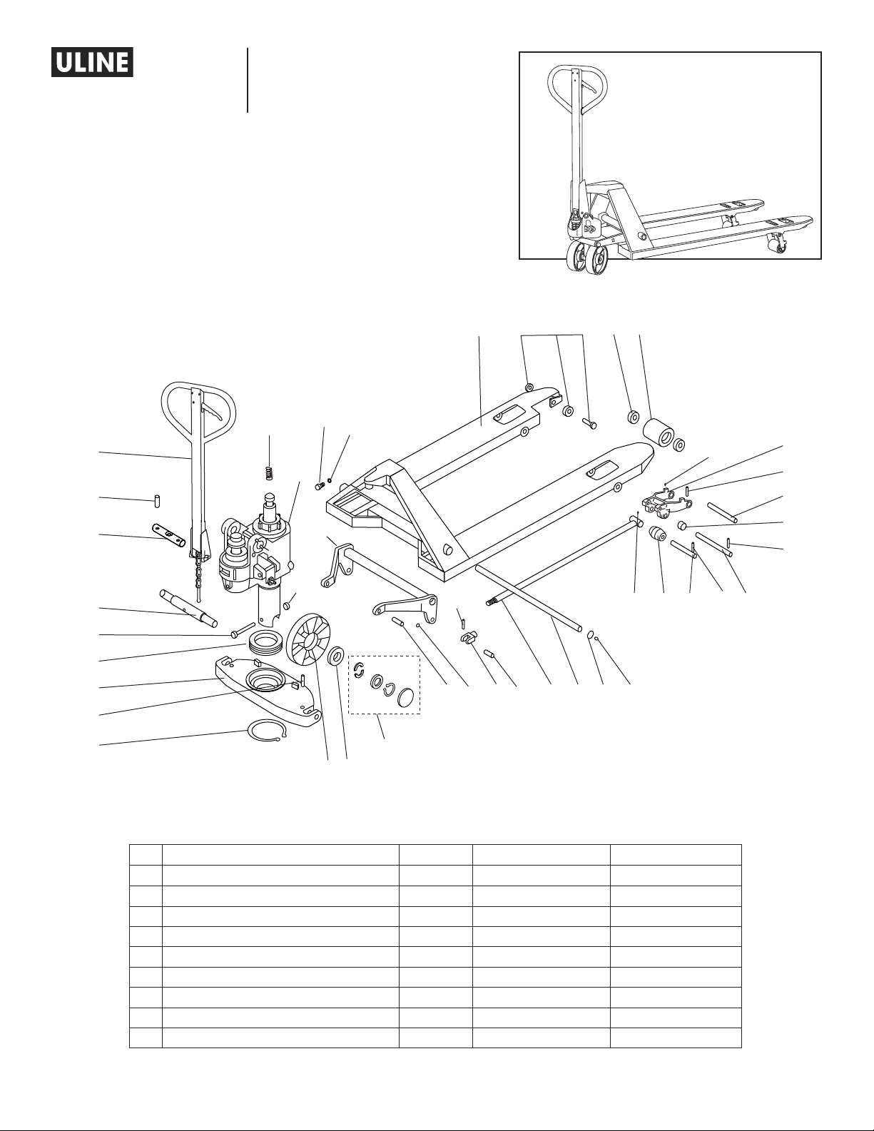
PALLET TRUCK
FRAME DIAGRAM
1
1-800-295-5510
uline.com
39
36
35
2
34
32
933
15
31
24
40
41
42
3
4
5
6
7
FRAME DIAGRAM PARTS LIST
# DESCRIPTION QTY. ULINE PART NO. MFG. PART NO.
1 Handle Assembly 1 H-1043-SHC B1
2 Pump (Standard) 1 H-1043PUMP PUMP STAND
3 Bolt 1 H-1365 - B 3 B3
4 Bearing 1 H-1365 - B 4 B4
5 Supporting Base 1 H-1043-B5 B5
6 Spring Pin 2 H-136 5 - B 6 B6
7 Retaining Ring For Axle 1 H-1043-B7 B7
8 Big (Steering) Wheel 2 H-1043-B8 B8
9 Bearing 8 H-1043-B9 B9
38
37
29
28
27
16
14 15
10
9
8
17
18 19
20
22 23
21 15
25
24
26
PAGE 1 OF 15 0321 PH-1043
Page 2
H-1043
PALLET TRUCK
1-800-295-5510
uline.com
FRAME DIAGRAM PARTS LIST CONTINUED
# DESCRIPTION QTY. ULINE PART NO. MFG. PART NO.
Big (Steering) Wheel Hardware Kit
Includes:
• Half Cirque (4)
10
• Bowl Washer (2)
• Retaining Ring for Axle (2)
• Dust Cover (2)
14 Pin 2 H-10 43-B14 B14
15 Oiler 8 H -1193 - B15 B15
16 Spring Pin 2 H-1483-B16 B16
17 Joint 2 H -1483 - B17 B17
18 Pin 2 H-1043-B18 B18
19 Straight Tappet 2 H-1483-B19 B19
20 Long Shaft 1 H-1043-B20 B20
21 Retaining Ring For Hole 2 H-1043-B21 B21
22 Oiler 4 H-1043-B22 B22
23 Roll Sheath 2 H-1043-23 B23
24 Spring Pin – 1¼" * 4 H-1043-B24 B24
25 Shaft 2 H-1043-25 B25
26 Shaft 2 H-1043-B26 B26
27 Spring Pin – 1⁄" ** 2 H-1043-B27 B27
28 Roll Ring 4 H-1043-B28 B28
29 Shaft 2 H -14 83-B29 B29
31 Frame Of Fork (Load) Wheel 2 H -10 43-B31 B31
32 Fork (Load) Wheel 2 H-1043-B35PU B35
Entry (Roller) Wheel Assembly Kit
Includes:
33
• Bolt (1)
• Entry Roller (1)
• Nut (1)
34 Fork Frame 1 H-1043-B40 B40
35 Spring Lock Washer 1 H -1043-B41 B41
36 Bolt 1 H-1043-B42 B42
37 Rocker Arm 1 H-1043-B43 B43
38 Nut 1 H-1366-B4 4 B44
39 Big Spring 1 H -14 83-B149 B149
40 Spring Pin 1 H-10 4 3 -B117 B117
41 Shaft 1 H -1043 - B118 B118
42 Big (Steering) Wheel Shaft 1 H-1366 - B2 B2
Replacement Fork (Load) Wheel With
Bearings Kit
Includes:
• Fork (Load) Wheel #32 (1)
• Bearing #9 (2)
*Replacement Spring Pins #24 – 1¼" 8 H-5632 BF2500-B24X8
**Replacement Spring Pins #27 – 1⁄" 8 H- 5631 BF2500-B27X8
Pallet Truck Pump Seal Kit (Not Shown) 1 H - 4182 ----------Pump Compression Spring (Not Shown) 1 H -1043PCS ----------Weight Label (Not Shown) 1 H-5390 -----------
PAGE 2 OF 15 0321 PH-1043
1 H- 6 017 B10-B13
1 H-5634 2500-B36B38B39
1 H-1043-WHKIT -----------
Page 3
H-1043
PALLET TRUCK
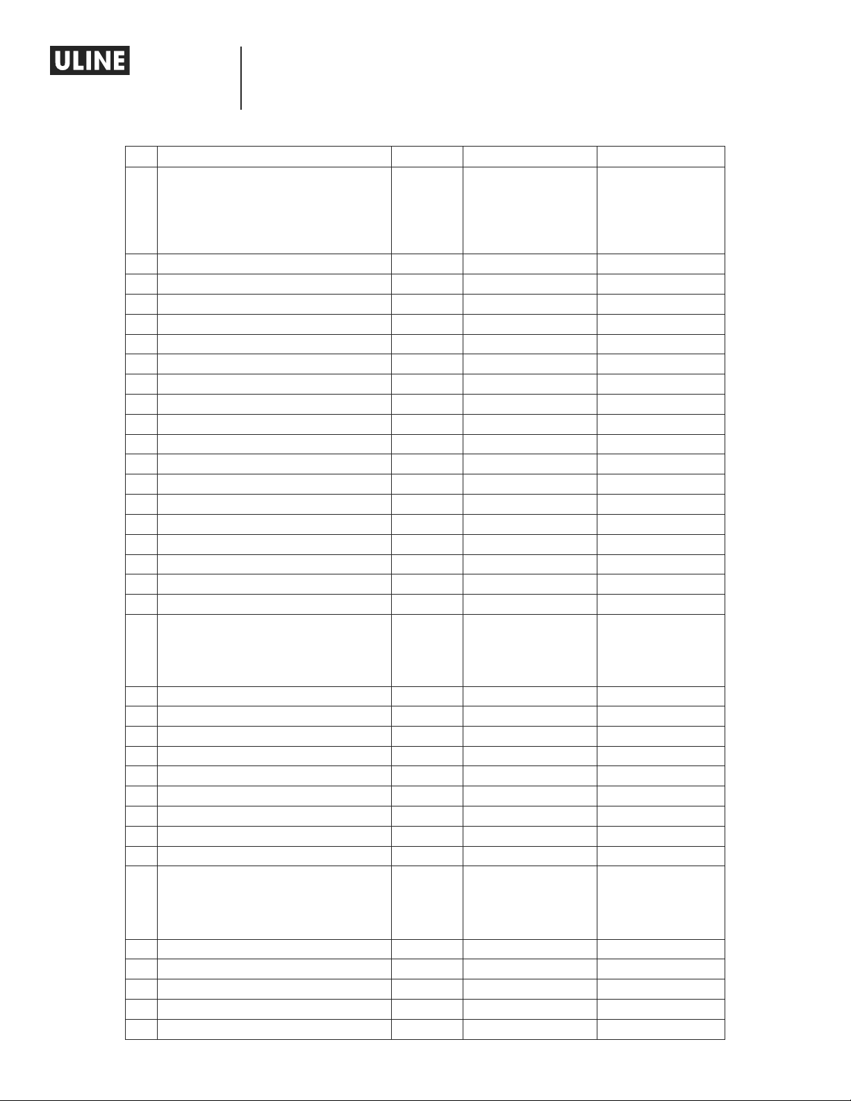
HANDLE DIAGRAM
1-800-295-5510
uline.com
1
2
3
4
5
6
8
7
A
9
10
11
12
14
HANDLE DIAGRAM PARTS LIST
# DESCRIPTION QTY. ULINE PART NO. MFG. PART NO.
A Handle Assembly 1 H-1043-SHC B1
1 Blade Spring 1 H-1366-B101 B101
2 Spring Pin 2 H-2721-B102 B102
3 Roller 1 H-2721-B103 B103
4 Spring Pin 1 H-2721-B104 B104
5 Spring Pin 1 H-2721-B105 B105
6 Spring Pin 1 H-2721-B106 B106
7 Handle 1 H-1043-B107Q B107
8 Handle Tube 1 H-1043B108 B108
9 Shaft 1 H-1043 -109 B109
10 Spring Pin 1 H-1043-B110 B110
11 Pressure Roller 1 H -10 43 -B111 B111
12 Bushing 1 H -10 4 3 -B112 B112
13 Bushing 2 H-10 4 3 -B114 B114
14 Pull Pole Assembly 1 H -10 4 3-B113 H-10 43 -B113 +B115+B116A S SEM B LY
15 Chain 1 H -10 4 3 -B115 B115
13
15
PAGE 3 OF 15 0321 PH-1043
Page 4
H-1043
PALLET TRUCK
1-800-295-5510
uline.com
30
36
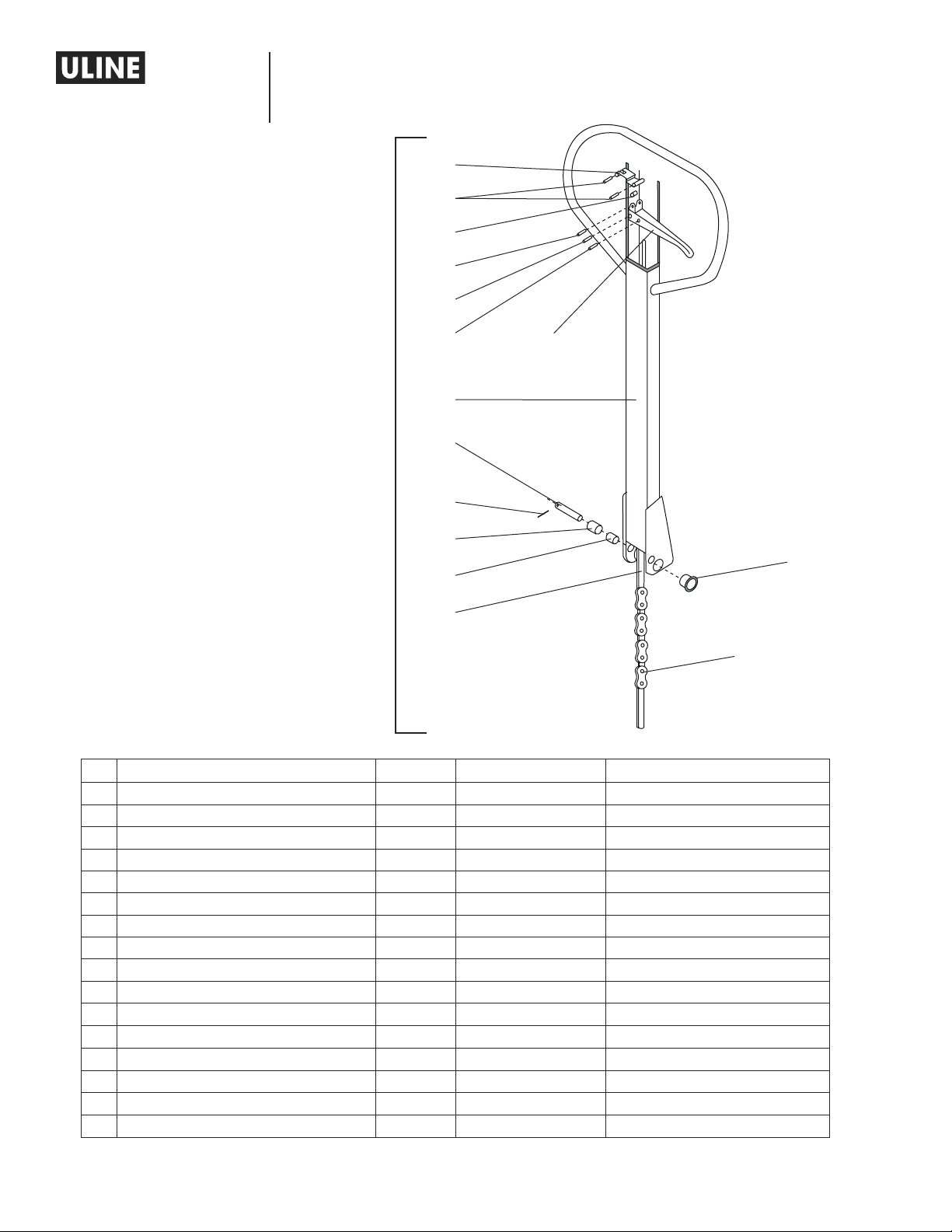
PUMP DIAGRAM
1
2
3
4
29
28
31
32
33
34
35
5
6
27
26
25
10
11
24
7
8
9
37
23
PUMP DIAGRAM PARTS LIST
# DESCRIPTION QTY. ULINE PART NO. MFG. PART NO.
1 Spring Pin 2 H -10 43 -B117 B117
2 Shaft 1 H -10 4 3-B118 B118
3 Plug 1 H -14 8 3 -B119 B119
4 Copper Washer 2 H-1043 -120 B120
22
21 20
10
19
18
17
15
12 13 14 4
11
16
PAGE 4 OF 15 0321 PH-1043
Page 5
H-1043
PALLET TRUCK
1-800-295-5510
uline.com
PUMP DIAGRAM PARTS LIST CONTINUED
# DESCRIPTION QTY. ULINE PART NO. MFG. PART NO.
5 Spring 1 H-1483- B121 B121
6 Spindle Of Damping Valve 1 H -1193 -B122 B122
7 Seat Of Damping Valve 1 H-1193 - B123 B123
8 Steel Ball 1 H-2721-B124 B124
9 Base 1 ----------- B125
10 Copper Washer 2 H-1043 -B126 B126
11 Bolt 2 H-1043 - B127 B127
12 Spring 1 H -119 3 -B128 B128
13 Strike Pin 1 H-1193 - B12 9 B129
14 O-Ring 1 H-1193 - B13 0 B130
15 Axle Sleeve 1 H-10 43-B131 B131
16 O-Ring 1 H-2721-B132 B132
17 Bolt (Setting Screw) 1 H-1043 - B133 B133
18 Nut (Setting Screw Nut) 1 H-1043 - B134 B134
19 Lever 1 H -104 3 - B135 B135
20 Bolt 1 H -104 3-B136 B136
21 Spring 1 H-2721-B137 B137
22 Ball Base 1 H-1782-B138 B138
23 Steel Ball 1 H-1782-B139 B139
24 Pin 1 H-104 3 - B140 B140
25 Y-Ring 1 H -1043-B141 B141
26 O-Ring 1 H -2721-B142 B142
27 Cylinder Cap 1 H-1043-B143 B143
28 O-Ring 1 H-10 43- B144 B144
29 Dust Ring 1 H -1043 - B145 B145
30 Steel Ball 1 H-1043-B146N B146
31 Pump Plunger 1 H -136 6 - B147 B147
32 Washer 1 H-1043-B148 B14 8
33 Big Spring 1 H-1483 - B149 B149
34 Dust Ring 1 H -1483-B150 B150
35 Y-Ring 1 H-1043 -B151 B151
36 Piston Rod 1 H -1043-B152 B152
37 Retaining Ring For Axle 1 H-1043-B153 B153
PAGE 5 OF 15 0321 PH-1043
Page 6

H-1043
PATÍN HIDRÁULICO
800-295-5510
uline.mx
DIAGRAMA DE LA ESTRUCTURA
39
1
40
41
42
3
4
5
6
38
32
20
933
21 15
22 23
25
15
24
31
24
29
28
27
26
34
36
35
2
37
16
14 15
17
18 19
7
8
10
9
LISTA DE PARTES DEL DIAGRAMA DE LA ESTRUCTURA
# DESCRIPCIÓN CANT. NO. DE PARTE DE ULINE NO. DE PARTE DEL FABRICANTE
1 Ensamble del Asa 1 H-1043-SHC B1
2 Bomba (Estándar) 1 H-1043PUMP PUMP STAND
3 Remache 1 H -1365-B3 B3
4 Soporte 1 H-1365-B4 B4
5 Base de Apoyo 1 H-1043-B5 B5
6 Pasador 2 H-1365 -B6 B6
7 Seguro para el Eje 1 H -1043 - B7 B7
8 Llanta Grande (de Dirección) 2 H-1043-B8 B8
9 Soporte 8 H-1043-B9 B9
PAGE 6 OF 15 0321 PH-1043
Page 7

H-1043
PATÍN HIDRÁULICO
800-295-5510
uline.mx
CONTINUACIÓN DE LISTA DE PARTES DEL DIAGRAMA DE LA ESTRUCTURA
# DESCRIPCIÓN CANT. NO. DE PARTE DE ULINE NO. DE PARTE DEL FABRICANTE
Big (Steering) Wheel Hardware Kit
Incluye:
• Medio Anillo (4)
10
• Rondana (2)
• Seguro para el Eje (2)
• Cubierta para Polvo (2)
14 Perno 2 H-1043-B14 B14
15 Grasera 8 H -1193 - B15 B15
16 Pasador 2 H-1483-B16 B16
17 Junta 2 H -1483 - B17 B17
18 Perno 2 H -1043-B18 B18
19 Barra Recta Deslizante 2 H-1483-B19 B19
20 Eje Largo 1 H-1043-B20 B20
21 Seguro para el Orificio 2 H-1043-B21 B21
22 Grasera 4 H-1043-B22 B22
23 Funda para Rodillo 2 H-1043-23 B23
24 Pasador de 1¼" * 4 ------------ -----------25 Eje 2 H-1043-25 B25
26 Eje 2 H-1043-B26 B26
27 Pasador de 1⁄" ** 2 ------------ ------------
28 Anillo de Rodillo 4 H-1043-B28 B28
29 Eje 2 H-1483- B29 B29
31 Armazón de la Llanta de Horquilla (Carga) 2 H-1043-B31 B31
32 Llanta de Horquilla (Carga) 2 H-1043-B35PU B35
Kit de Ensamble de la Llanta de Acceso (Rodillo)
Incluye:
33
• 1 Perno
• 1 Rodillo para Entrada
• 1 Tuerca
34 Marco de Horquilla 1 H-1043-B40 B40
35 Rosca de Resorte 1 H-1043-B41 B41
36 Remache 1 H -1043 -B42 B42
37 Brazo Oscilante 1 H-1043-B43 B43
38 Tuerca 1 H -1366-B44 B44
39 Resorte Grande 1 H-1483-B149 B149
40 Pasador 1 H -10 43 -B117 B117
41 Eje 1 H-10 4 3 -B118 B118
42 Eje de la Llanta Grande (de Dirección) 1 H -1366-B2 B2
Kit de Reemplazo de la Llanta de Horquilla (Carga)
con Baleros
Incluye:
• Llanta de Horquilla (Carga) #32 (1)
• Soporte #9 (2)
*Pasadores de Reemplazo #24 de 1¼" 8 H-5632 BF2500-B24X8
**Pasadores de Reemplazo #27 de 1⁄” 8 H-5631 BF2500 -B27X8
Kit del Sello de la Bomba del Patín Hidráulico
(No se Muestra)
Resorte de Compresión de la Bomba (No se Muestra) 1 H-1043PCS -----------Etiqueta del Peso (No se Muestra) 1 H-5390 ------------
PAGE 7 OF 15 0321 PH-1043
1 H-6017 B10 -B13
1 H-5634 2500-B36B38B39
1 H-1043-WHKIT ------------
1 H- 4182 ------------
Page 8

H-1043
PATÍN HIDRÁULICO
DIAGRAMA DE LA ASA
800-295-5510
uline.mx
1
2
3
4
5
6
8
7
LISTA DE PARTES DEL DIAGRAMA DE LA ASA
# DESCRIPCIÓN CANT. NO. DE PARTE DE ULINE NO. DE PARTE DEL FABRICANTE
A Ensamble de la Asa 1 H-1043-SHC B1
1 Resorte de Lámina 1 H-1366 -B101 B101
2 Pasador 2 H -2721-B102 B102
3 Rodillo 1 H-2721-B103 B103
4 Pasador 1 H -2721-B104 B104
5 Pasador 1 H -2721-B105 B105
6 Pasador 1 H -2721-B106 B106
7 Palanca 1 H -1043-B107Q B107
8 Poste de Palanca 1 H-1043B108 B108
9 Eje 1 H-1043-109 B109
10 Pasador 1 H-1043-B110 B110
11 Rodillo de Presión 1 H-10 4 3 -B111 B111
12 Casquillo 1 H -1043 - B112 B112
13 Casquillo 2 H -1043 - B114 B114
14 Ensamble del Poste de Tracción 1 H-1 0 4 3 -B113 H-10 43 -B113 +B115+B116A S SEM B LY
15 Cadena 1 H -10 4 3-B115 B115
A
9
10
11
13
12
14
15
PAGE 8 OF 15 0321 PH-1043
Page 9

H-1043
PATÍN HIDRÁULICO
800-295-5510
uline.mx
30
36
DIAGRAMA DE LA BOMBA
1
2
3
4
5
6
31
32
33
34
35
29
28
27
26
25
10
11
24
7
8
9
37
22
23
21 20
10
11
LISTA DE PARTES DEL DIAGRAMA DE LA BOMBA
# DESCRIPCIÓN CANT. NO. DE PARTE DE ULINE NO. DE PARTE DEL FABRICANTE
1 Pasador 2 H-10 4 3-B117 B117
2 Eje 1 H-104 3 -B118 B118
3 Tapón 1 H -14 8 3 -B119 B119
4 Rondana de Bronce 2 H-1043-120 B120
12 13 14 4
15
19
18
17
16
PAGE 9 OF 15 0321 PH-1043
Page 10

H-1043
PATÍN HIDRÁULICO
800-295-5510
uline.mx
CONTINUACIÓN DE LA LISTA DE PARTES DEL DIAGRAMA DE LA BOMBA
# DESCRIPCIÓN CANT. NO. DE PARTE DE ULINE NO. DE PARTE DEL FABRICANTE
5 Resorte 1 H-1483- B121 B121
6 Cabezal de Válvula de Amortiguación 1 H -119 3 -B122 B122
7 Asiento de Válvula de Amortiguación 1 H -1193 - B12 3 B123
8 Balín de Acero 1 H-2721- B124 B124
9 Base 1 ----------- B125
10 Rondana de Bronce 2 H-1043-B126 B126
11 Remache 2 H-1043-B127 B127
12 Resorte 1 H -1193 - B128 B128
13 Perno de Golpe 1 H -119 3 -B129 B129
14 Anillo-O 1 H -119 3 -B130 B130
15 Brazo de Eje 1 H-1043 - B131 B131
16 Anillo-O 1 H-2721- B132 B132
17 Remache (Tornillo de Ajuste) 1 H-10 43-B133 B133
18 Tuerca (Tuerca del Tornillo de Ajuste) 1 H-1043-B134 B134
19 Palanca 1 H-1043-B135 B135
20 Remache 1 H-1043- B136 B136
21 Resorte 1 H-2721-B137 B137
22 Base del Balín de Acero 1 H -178 2- B13 8 B138
23 Balín de Acero 1 H-1782-B139 B139
24 Pasador 1 H-104 3 - B140 B14 0
25 Anillo-Y 1 H -1043 - B141 B141
26 Anillo-O 1 H-2721-B142 B142
27 Tapa del Cilindro 1 H-1043-B143 B143
28 Anillo-O 1 H -1043-B144 B144
29 Anillo para Polvo 1 H-1043 - B145 B145
30 Balín de Acero 1 H -1043 - B146 N B146
31 Bomba de Émbolo 1 H-1366-B147 B147
32 Rondana 1 H-10 43 - B148 B14 8
33 Resorte Grande 1 H -1483-B149 B149
34 Anillo para Polvo 1 H -1483-B15 0 B150
35 Anillo-Y 1 H -1043- B151 B151
36 Barra de Pistón 1 H-1043-B152 B152
37 Seguro para el Eje 1 H -1043- B153 B153
PAGE 10 OF 15 0321 PH-1043
Page 11

H-1043
TRANSPALETTE
SCHÉMA DE LA STRUCTURE
1-800-295-5510
uline.ca
34
32
933
38
36
35
2
37
10
9
8
39
1
40
41
42
3
4
5
6
7
LISTE DES PIÈCES DU SCHÉMA DE LA STRUCTURE
16
14 15
17
18 19
20
21 15
22 23
25
15
24
31
24
29
28
27
26
# DESCRIPTION QTÉ RÉF. U LINE RÉF. DU FABRICANT
1 Assemblage de la poignée 1 H-1043-SHC B1
2 Pompe (standard) 1 H-1043PUMP PUMP STAND
3 Boulon 1 H-1365 - B 3 B3
4 Roulement 1 H-1365 - B 4 B4
5 Base de support 1 H-1043- B5 B5
6 Cheville ressort 2 H-136 5 - B 6 B6
7 Bague de retenue pour essieu 1 H-1043-B7 B7
8 Grande roue (directrice) 2 H-1043- B8 B8
9 Palier 8 H-1043-B9 B9
PAGE 11 OF 15 0321 PH-1043
Page 12

H-1043
TRANSPALETTE
1-800-295-5510
uline.ca
LISTE DES PIÈCES DU SCHÉMA DE LA STRUCTURE SUITE
# DESCRIPTION QTÉ RÉ F. ULINE RÉF. DU FABRICANT
Ensemble de matériel d'installation de la grande roue (directrice)
Comprend :
• Demi-cercle (4)
10
• Rondelle (2)
• Bague de retenue pour essieu (2)
• Couvercle antipoussière (2)
14 Tige 2 H -1043 - B14 B14
15 Huileur 8 H-1193 - B15 B15
16 Cheville ressort 2 H-1483 - B16 B16
17 Joint 2 H -1483- B17 B17
18 Tige 2 H-1043 - B18 B18
19 Poussoir droit 2 H -1483- B19 B19
20 Long arbre 1 H-1043-B20 B20
21 Bague de retenue pour trou 2 H-1043-B21 B21
22 Huileur 4 H-1043-B22 B22
23 Gaine de roulement 2 H-1043-23 B23
24 Cheville ressort – 1 ¼ po* 4 ----------- ----------25 Arbre 2 H-1043-25 B25
26 Arbre 2 H-1043-B26 B26
27 Cheville ressort – 1 ⁄ po** 2 ----------- ----------28 Anneau de roulement 4 H-1043-B28 B28
29 Arbre 2 H-1483 - B29 B29
31 Armature de roue (porteuse) de fourche 2 H -1043-B31 B31
32 Roue (porteuse) de fourche 2 H -1043- B35PU B35
Ensemble de roue (rouleau) d'entrée
Comprend :
33
• Boulon (1)
• Rouleau d'entrée (1)
• Écrou (1)
34 Cadre de fourche 1 H-1043 -B40 B40
35 Rondelle ressort à becs 1 H-1043 -B41 B41
36 Boulon 1 H-1043-B42 B42
37 Bras de bascule 1 H-1043-B43 B43
38 Écrou 1 H-1366-B44 B44
39 Gros ressort 1 H-1483-B149 B149
40 Cheville ressort 1 H-10 4 3 -B117 B117
41 Arbre 1 H-1043 - B118 B118
42 Arbre de grande roue (directrice) 1 H-1366 - B2 B2
Roue (porteuse) de fourche de rechange avec ensemble de paliers
Comprend :
• Roue (porteuse) de fourche nº 32 (1)
• Palier nº 9 (2)
*Chevilles ressorts de rechange nº 24 – 1 ¼ po 8 H-5632 BF2500-B24X8
**Chevilles ressorts de rechange nº 27 – 1 ⁄ po 8 H-5631 BF2500-B27X8
Ensemble de joints de pompe de transpalette (non illustré) 1 H-4182 ----------Ressort de pression de pompe (non illustré) 1 H-1043PCS ----------Étiquette de poids (non illustrée) 1 H-5390 -----------
PAGE 12 OF 15 0321 PH-1043
1 H - 6017 B10- B13
1 H-5634 2500-B36B38B39
1 H-1043-WHKIT ------------
Page 13

H-1043
TRANSPALETTE
SCHÉMA DE LA POIGNÉE
1-800-295-5510
uline.ca
1
2
3
4
5
6
8
7
A
LISTE DES PIÈCES DU SCHÉMA DE LA POIGNÉE
# DESCRIPTION QTÉ RÉF. ULINE RÉF. DU FABRICANT
A Assemblage de la poignée 1 H-1043-SHC B1
1 Ressort à lame 1 H-1366 -B101 B101
2 Cheville ressort 2 H-2721- B102 B102
3 Rouleau 1 H-2721-B103 B103
4 Cheville ressort 1 H-2721- B104 B104
5 Cheville ressort 1 H-2721- B105 B105
6 Cheville ressort 1 H-2721- B106 B106
7 Poignée 1 H-1043 -B107Q B107
8 Tube de poignée 1 H-1043B108 B108
9 Arbre 1 H-1043 -109 B109
10 Cheville ressort 1 H-1043- B110 B110
11 Rouleau de pression 1 H -1043 - B111 B111
12 Bague 1 H -10 43 -B112 B112
13 Bague 2 H -10 4 3 -B114 B114
14 Assemblage de tige à tirer 1 H -1043 - B113 H -1043 - B113+B115+ B116 ASS E MBLY
15 Chaîne 1 H-10 43 -B115 B115
9
10
11
13
12
14
15
PAGE 13 OF 15 0321 PH-1043
Page 14

H-1043
TRANSPALETTE
1-800-295-5510
uline.ca
30
36
SCHÉMA DE LA POMPE
1
2
3
4
5
6
31
32
33
34
35
29
28
27
26
25
10
11
24
7
8
9
37
22
23
21 20
10
LISTE DES PIÈCES DU SCHÉMA DE LA POMPE
# DESCRIPTION QTÉ RÉF. ULINE RÉF. DU FABRICANT
1 Cheville ressort 2 H -1043 - B117 B117
2 Arbre 1 H -10 4 3-B118 B118
3 Bouchon 1 H -14 8 3 -B119 B119
4 Rondelle en cuivre 2 H -1043 -120 B120
19
18
17
15
12 13 14 4
11
16
PAGE 14 OF 15 0321 PH-1043
Page 15

H-1043
TRANSPALETTE
1-800-295-5510
uline.ca
LISTE DES PIÈCES DU SCHÉMA DE LA POMPE SUITE
# DESCRIPTION QTÉ RÉF. ULINE RÉF. DU FABRICANT
5 Pump Spring 1 H-1483 -B121 B121
6 Tige du clapet d'amortissement 1 H-1193 - B122 B122
7 Siège du clapet d'amortissement 1 H-1193 - B123 B123
8 Bille d'acier 1 H-2721-B124 B124
9 Base 1 ----------- B125
10 Rondelle en cuivre 2 H-1043 - B126 B126
11 Boulon 2 H -1043-B127 B127
12 Ressort 1 H -119 3 -B128 B128
13 Tige de touche 1 H-1193 - B12 9 B129
14 Joint torique 1 H-1193 - B13 0 B130
15 Manchon d'essieu 1 H-10 43-B131 B131
16 Joint torique 1 H-2721-B132 B132
17 Boulon (Vis de blocage) 1 H -1043-B133 B133
18 Écrou (Écrou de vis de blocage) 1 H-1043-B134 B134
19 Levier 1 H -1043-B135 B135
20 Boulon 1 H-1043-B136 B136
21 Ressort 1 H-2721-B137 B137
22 Socle à bille 1 H -1782- B138 B138
23 Bille d'acier 1 H-1782-B139 B139
24 Tige 1 H-10 43- B14 0 B140
25 Anneau en Y 1 H -1043 -B141 B141
26 Joint torique 1 H -2721-B142 B142
27 Coiffe de cylindre 1 H-1043-B143 B143
28 Joint torique 1 H-104 3 - B144 B144
29 Anneau de glissement 1 H -1043 - B145 B145
30 Bille d'acier 1 H -1043 - B146N B146
31 Piston 1 H-1366-B147 B147
32 Rondelle 1 H -1043 - B148 B148
33 Gros ressort 1 H-1483 - B149 B149
34 Anneau de glissement 1 H -1483-B150 B150
35 Anneau en Y 1 H-1043-B151 B151
36 Tige de piston 1 H-1043-B152 B152
37 Bague de retenue pour essieu 1 H-1043-B153 B153
PAGE 15 OF 15 0321 PH-1043
 Loading...