

Page 1
H-1024 , H-1025
H-1026
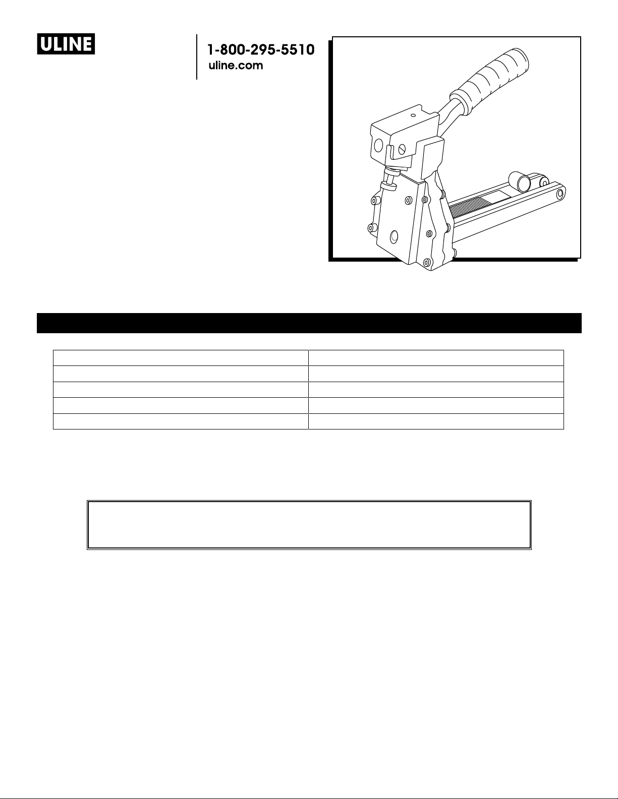
MANUAL
CARTON STAPLER
STAPLER SPECIFICATIONS
Dimensions (L x H x W) 15 x 11½ x 4½"
Weight (Without Fasteners) 3.75 lb.
H-1025/H-1026 Staple Specification S-289 C58 Stick and/or S-1396 C34 Stick
H-1024 Staple Specification S-1397 A58 Stick
Staple Capacity 100 Staples
WARNING
Before operating this stapler familiarize yourself with the safety warnings and
instructions in this manual. Keep these instructions with the stapler for future
reference. If you have any questions, contact Uline at 1-800-295-5510.
0812 IH-1024PAGE 1 OF 7
Page 2
SAFETY INSTRUCTIONS
SAFETY INSTRUCTIONS
1. Read the manual and understand all safety
instructions before operating the stapler. If you have
questions, contact Uline at 1-800-295-5510.
2. Always wear protective equipment; e.g., safety
glasses, hearing protection and head protection.
3. Do not place your hand or any other body part in
the staple clinching area.
4. Never point the stapler at yourself or anyone else.
LOADING THE STAPLER
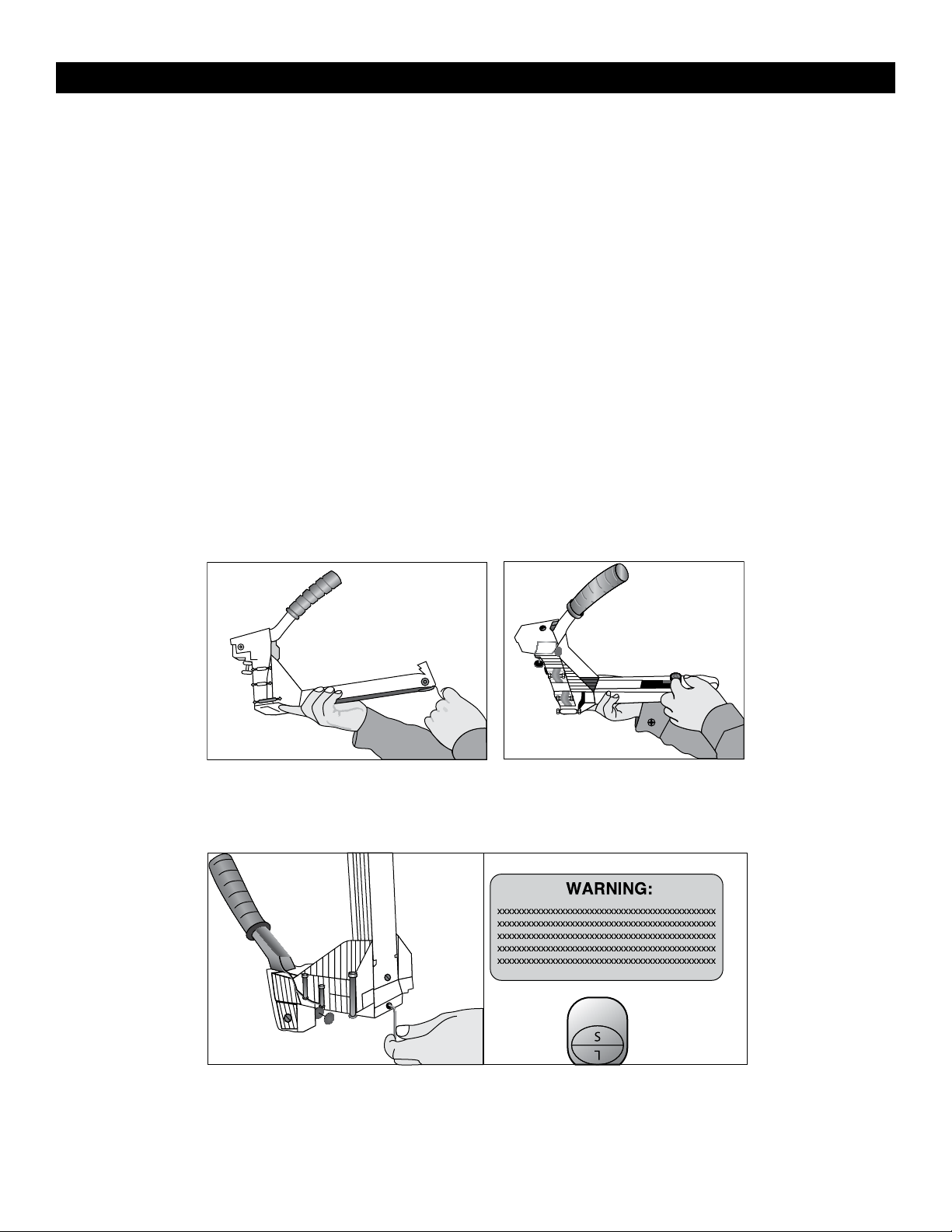
1. Pull the pusher back until it stops on pusher pivots.
Rotate pusher to position. (See Figure 1)
2. Insert up to 2 sticks of appropriate staples into the
magazine. Let the sticks slide forward to the front of
the magazine. (See Figure 2)
3. Pull the pusher back to an upright position and
gently let the pusher slide forward against the
staples. Do not let the pusher slide forward and
strike the staples at high speed as this may deform
the staples and damage the stapler.
ADJUSTING STAPLE LEG LENGTH
1. Loosen the set screw with a 3mm Allen wrench on
the bottom. (See Figure 3)
2. Turn adjusting rod 180º with a screw driver to the
desired setting.
3. If you are using ¾" staples set L up.
4. If you are using 5⁄8" staples set S up. (See Figure 4)
5. Tighten the set screw.
Figure 1 Figure 2
Figure 3 Figure 4
0812 IH-1024PAGE 2 OF 7
Page 3
SAFETY INSTRUCTIONS (CONTINUED)
CLINCH ADJUSTMENT
Loosen securing nut closest to body. Turn adjustment
nut clockwise to loosen clinch. Turn adjustment nut
counter-clockwise to tighten clinch. After adjusting,
tighten securing nut. (See Figure 5)
DEPTH ADJUSTMENT
1. Loosen front 2 screws with a 4 mm Allen w rench.
(See Figure 6)
2. Push the body up and adjust to the desired depth.
(See Figure 7)
Figure 6
Figure 5
Figure 7
0812 IH-1024PAGE 3 OF 7
Page 4

OPERATING INSTRUCTIONS
WARNING
1. Protect your eyes and ears.
a. Wear safety glasses with side shields.
b. Wear hearing protection.
c. Ensure that anyone in the vicinity wears safety protection.
2. To prevent accidental injuries, never place a hand or any other body part in
the staple clinching area or adjustment window.
3. Never point the stapler towards you or anyone else.
4. Always handle the stapler with care. Never pull the trigger unless stapler is
ready for operation.
5. Check and replace any damaged or worn components on the stapler.
BASIC OPERATION
1. Insert the staples into the stapler following the
loading instructions.
2. Grasp the handle with one hand on box in line
with the desired staple location. There is a small
projection on either side of the magazine seat as an
aid in locating the position of the staple.
3. For strongest closure, use staples close to the ends
of the box.
CLEARING A JAM
1. Pull pusher back and rotate to a locked position.
(See Figure 8)
2. Insert needle nose pliers or screw driver to clear jam.
(See Figure 9)
3. Slowly release pusher back to position.
Figure 8
Figure 9
0812 IH-1024PAGE 4 OF 7
Page 5

TROUBLE SHOOTING
WARNING
Stop using the stapler immediately if any of the following problems occur.
Serious personal injury could occur. Any repairs or replacements must be
done by a qualified person or authorized service center only.
PROBLEM CAUSE REMEDY
Excessive jams Teeth screws are loose or
staples are wrong size.
Uneven clinch Wrong staple size. Check for proper leg length adjustment and
Unclinched staple Teeth are loose or broken. Check and replace teeth as needed.
Tighten screws and check staples.
clincher size.
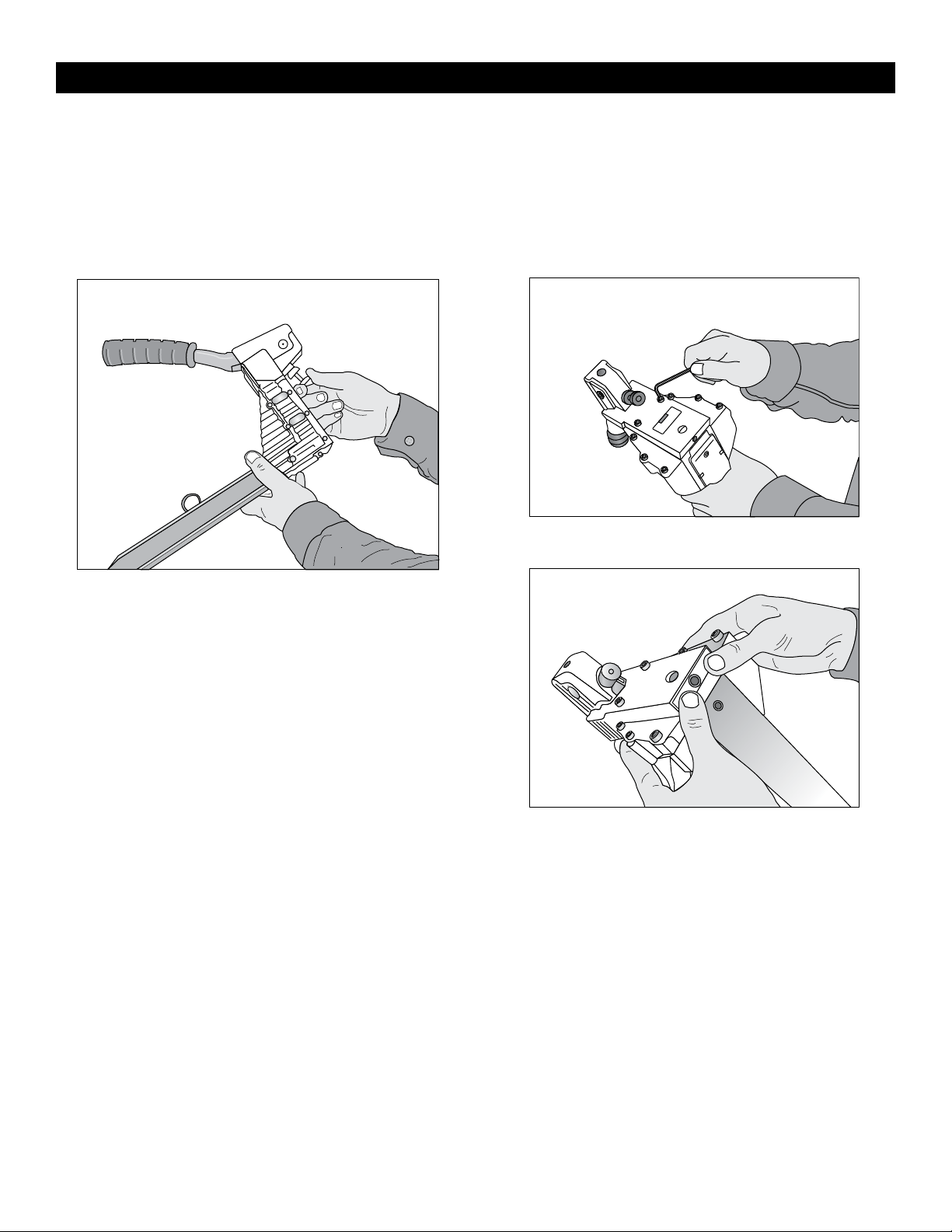
TEETH REPLACEMENT
1. Loosen screws and nut with an 8 mm wrench and
4 mm Allen wrench. (See Figure 10)
2. Remove the magazine assembly. (See Figure 11)
3. Loosen screws with 3 mm Allen wrench.
(See Figure 12)
4. Change teeth one at a time to prevent reverse teeth.
Figure 10 Figu re 11 Figu re 12
0812 IH-1024PAGE 5 OF 7
Page 6

DRIVER REPLACEMENT
TROUBLE SHOOTING (CONTINUED)
1. Loosen screw and nut with a 8 mm spanner wrench
and a 4 mm Allen wrench. (See Figure 13)
2. Remove the magazine assembly. (See Figure 14)
3. Loosen the set screw with a 3 mm Allen wrench to
unlock the adjusting rod. (See Figure 15)
4. Remove the linkage mechanism and adjusting rod
simultaneously from the body.
5. Loosen the pivot screws with flat screwdriver.
Remove handle and linkage mechanism.
6. Remove the spring pin with a hammer and 5 mm
straight rod.
7. Loosen screws with a 3 mm Allen wrench. Take off
the spring pin with a hammer and 6 mm straight rod.
(See Figure 16)
Fi gure 13
Figure 15
Fi gur e 14
Figu re 16
0812 IH-1024PAGE 6 OF 7
Page 7

PUSHER SPRING REPLACEMENT
TROUBLE SHOOTING (CONTINUED)
1. Loosen the screws and nut with a 8mm spanner
wrench and a 4 mm Allen wrench. (See Figure 17)
2. Remove the magazine assembly. (See Figure 18)
3. Pull the pusher back until it stops on the rod, rotate
the pusher to position.
4. Push the magazine seat back and remove it from
the magazine.
Fig u re 17 Figu re 18
5. Loosen the screw and nut with a 2.5 mm Allen
wrench and 7mm socket wrench. (See Figure 19)
6. Loosen the rod with a 6mm offset wrench and
remove the pusher guides. Remove the pusher.
(See Figure 20)
7. Remove the spring pin with a hammer and 4 mm
straight rod. (See Figure 21)
Figu re 19
π
Figure 20 Figure 21
CHICAGO • ATLANTA • DALLAS • LOS ANGELES • MINNEAPOLIS • NYC/PHILA • SEATTLE • MEXICO • CANADA
1- 8 0 0 -295-5510
uline.com
0812 IH-1024PAGE 7 OF 7
 Loading...