

Page 1
Échelon
™
U
S
E
R
M
A
N
U
A
L
Page 2

U-LINE CORPORATION LIMITED WARRANTY
U-Line Corporation warrants each U-Line product to be free from defects in materials and
workmanship for a period of one year from the date of purchase; and warrants the sealed
system (consisting of the compressor, the condenser, the evaporator, the hot gas bypass
valve, the dryer and the connecting tubing) in each U-Line product to be free from defects
in materials and workmanship for a period of five years from the date of purchase. During
the initial one-year warranty period for all U-Line products U-Line shall: (1) at U-Line’s
option, repair any product or replace any part of a product that breaches this warranty;and
(2) for all Marine, R V and Domestic U-Line products sold and serviced in the United States
(including Alaska and Hawaii)and Canada, U-Line shall cover the labor costs incurred in
connection with the replacement of any defective part. During years two through fiv e of the
warranty period for the sealed system, U-Line shall:. (1) repair or replace any par t of the
sealed system that breaches this warranty;and (2) for all Marine, RV and Domestic U-Line
products sold and serviced in the United States (including Alaska and Hawaii)and Canada,
U-Line shall cover the labor costs incurred in connection with the replacement of any def ective part of the sealed system. All other charges, including transportation charges for
replacements under this warranty and labor costs not specifically covered by this warranty, shall be borne by you. This warranty is extended only to the original purchaser of the
U-Line product. The Registration Card included with the product should be promptly completed by you and mailed back to U-Line or you can register on-line at
www.ulineservice.com.
The following are excluded from this limited warranty: installation charges; damages
caused by disasters or acts of God, such as fire, floods, wind and lightening; damages
incurred or resulting from shipping, improper installation, unauthorized modification, or misuse/abuse of the product; customer education calls; food loss/spoilage; door and water
level adjustments (e xcept during the first 90 days from the date of purchase);defrosting the
product; adjusting the controls; door reversal;or cleaning the condenser.
If a product defect is discovered during the applicable warranty period, you must promptly
notify either the dealer from whom you purchased the product or U-Line at P.O.Box 23220,
Milwaukee, Wisconsin 53223 or at 414-354-0300. In no event shall such notification be
received later than 30 days after the expiration of the applicable warranty period. U-Line
may require that defective parts be returned, at your expense, to U-Line’s factory in
Milwaukee, Wisconsin, for inspection. Any action by you for breach of warranty must be
commenced within one year after the expiration of the applicable warranty period.
This limited warranty is in lieu of any other warranty, express or implied, including,
but not limited to any implied warranty of merchantability or fitness for a particular
purpose; pro vided ho wever,that to the extent required by law ,implied warranties are
included but do not extend beyond the duration of the express warranty first set
forth above. U-Line’s sole liability and your exclusive remedy under this warranty is
set forth in the initial paragraph above. U-Line shall have no liability whatsoever for
any incidental,consequential or special damages arising from the sale,use or installation of the product or from any other cause whatsoever, whether based on warranty (express or implied) or otherwise based on contract, tort or any other theory
of liability.
Some states do not allow limitations on how long an implied warranty lasts or the e xclusion
or limitation of incidental or consequential damages, so the above limitations ma y not apply
to you. This warranty gives you specific legal rights, and you may also have other rights
which vary from state to state.
Page 3
INTRODUCTION
Congratulations on your purchase of the U-Line 2075DWRR drawer
unit. A pioneer in the field for more than 40 years, U-Line is the world’s
number one manufacturer of built-in, under-counter ice making and specialty refrigeration products. U-Line dedicates 100% of its research and
development to these products. The result: U-Line technology leads the
market with innovation, design, depth of product line and performance.
U-Line also backs customers with a strong dealer network.
U-Line’s commitment to quality even extends to environmentally safe
packaging. U-Line products are making life more convenient in homes,
businesses, and hotels around the world.
PLEASE READ all instructions completely before attempting
to install or operate the unit.
Once you have your unit installed, we suggest you keep this manual in a
safe place for future reference. Should any problems occur, refer to the
TROUBLESHOOTING section of this manual. This information will help
you quickly identify a problem and get it remedied. In the event you
require assistance, please contact the dealer where you purchased your
unit.
PLEASE RECORD YOUR MODEL’S INFORMATION
Whenever you call to request information or service, you will need to
know your model number and serial number. You can find this information on the serial plate located on the inside wall of your unit and on the
product registration card.
PRODUCT REGISTRATION CARD
The package containing this manual also includes your product registration information. Warranty coverage begins at the time your unit was
purchased.
NOTE
Complete and mail the Product Registration Card as soon as
possible to validate the registration date. You may also register the product online at www.U-LineService.com.
1
Page 4

If you do not return your Product Registration Card, U-Line will use the
date of sale to the U-Line distributor as the first date of
warranty for your unit. Please also record the purchase date of your ULine unit and your dealer’s name, address and telephone number.
Model Number: ______________________________________
Serial Number: ______________________________________
Purchase Date: ______________________________________
Dealer Name: ______________________________________
Dealer Address: ______________________________________
Dealer Telephone: ______________________________________
Keep this manual and the sales receipt together in a safe place for further
reference.
TABLE OF CONTENTS
INTRODUCTION . . . . . . . . . . . . . . . . . . . . . . . . . . . . . . . . . . . .1
SAFETY PRECAUTIONS . . . . . . . . . . . . . . . . . . . . . . . . . . . . . . .3
INSTALLATION . . . . . . . . . . . . . . . . . . . . . . . . . . . . . . . . . . . .5
LEVELING THE UNIT . . . . . . . . . . . . . . . . . . . . . . . . . . . . . . . . .8
BUILT-IN INSTALLATION . . . . . . . . . . . . . . . . . . . . . . . . . . . . .10
CUSTOM DRAWER PANELS . . . . . . . . . . . . . . . . . . . . . . . . . .11
INITIAL START-UP AND ADJUSTING THE
TEMPERATURE CONTROL . . . . . . . . . . . . . . . . . . . . . . . . . . . .17
OPERATION . . . . . . . . . . . . . . . . . . . . . . . . . . . . . . . . . . . . .20
CLEANING & MAINTENANCE . . . . . . . . . . . . . . . . . . . . . . . . . .23
STORAGE . . . . . . . . . . . . . . . . . . . . . . . . . . . . . . . . . . . . . . .25
TROUBLESHOOTING . . . . . . . . . . . . . . . . . . . . . . . . . . . . . . . .26
IF SERVICE IS REQUIRED . . . . . . . . . . . . . . . . . . . . . . . . . . . . .27
User’s Manual
2
Page 5
SAFETY PRECAUTIONS
Do not attempt to install or operate your unit until you have read the safety precautions in this manual. Safety items throughout this manual are
labeled with a Danger, Warning or Caution based on the risk type.
DEFINITIONS
Danger means that failure to follow this safety statement
may result in severe personal injury or death.
Warning means that failure to follow this safety statement
may result in extensive product damage, serious personal
injury, or death.
CAUTION
Caution means that failure to follow this safety statement
may result in minor or moderate personal injury, property or
equipment damage.
!
WARNING
DANGER
! !
3
Page 6

GENERAL PRECAUTIONS
RISK OF CHILD ENTRAPMENT. Before you throw away your
old refrigerator or freezer, take off the doors and leave
shelves in place so that children may not easily climb inside.
• Never attempt to repair or perform maintenance on the
unit until the electricity has been disconnected.
• Altering, cutting of power cord, removal of power cord,
removal of power plug, or direct wiring can cause serious
injury, fire and/or loss of property and/or life and will void
the warranty.
•The anti-tip kit must be installed on this unit before it is
used. Never use the drawers as steps or a shelf to support more than the drawers’ content.
CAUTION
•Do not lift unit by drawer’s handle.
• Failure to clean the condenser every three months can
cause the unit to malfunction. This could void the warranty.
•Never install the unit behind closed doors. Be sure front
grille is free of obstruction. Obstructing free air flow can
cause the unit to malfunction, and may void the warranty.
CAUTION
• Use only genuine U-Line replacement parts. Imitation parts
can damage the unit, and may void the warranty.
!
WARNING
DANGER
! !
User’s Manual
4
Page 7
INSTALLATION
SITE PREPARATION
Your U-Line drawer unit must be installed under a counter or in a wall.
The unit is designed so it can be installed next to a wall, because the
crisper can be accessed from either side.
1. Position the unit on a flat, level surface, capable of supporting the
entire weight of the unit. Remember the unit will be significantly
heavier once it is fully loaded.
2. This unit requires grounded and polarized 115 VAC, 60Hz, 15A circuit (normal household current).
ELECTROCUTION HAZARD!
Electrical Grounding Required. This appliance
is equipped with a three prong (grounding)
polarized plug for your protection against possible shock hazards.
• NEVER remove the round grounding prong from the plug.
•NEVER use a two-prong grounding adapter.
•NEVER use an extension cord to connect power to the
unit.
Where a two-prong wall receptacle is encountered or a
longer power cord is required, contact a qualified electrician
to have it replaced in accordance with applicable electrical
codes.
DANGER
! !
5
Page 8
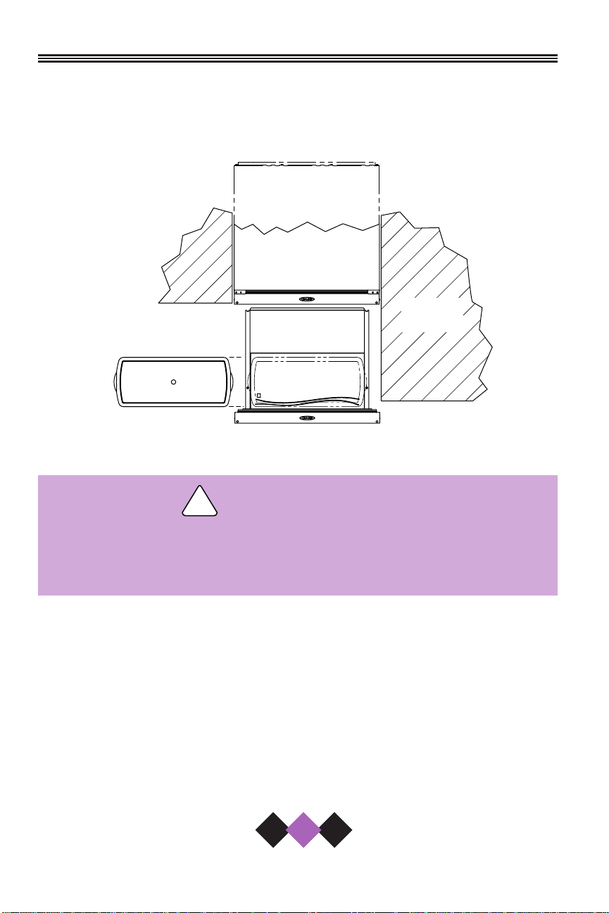
Your U-Line Drawer unit is designed so it can be installed next to the wall
on either side because the crisper can be accessed from either side
(Figure 1, 2).
Figure 1 – Right wall installation
The anti-tip kit must be installed on this unit before it is used.
Never use the drawers as steps or a shelf to support more
than the drawers’ content.
3. The unit must be installed in a wall or under a counter top to allow
for the installation of the anti-tip kit. The drawer unit can be installed
with an appliance or fixture located in front of it, as long as there is
adequate clearance for the drawer to be opened and removed when
servicing (Figure 3).
U-Line recommends you consider additional clearance in front of the
open drawer for convenience.
!
WARNING
User’s Manual
6
CABINET
OR WALL
DWR001
Page 9
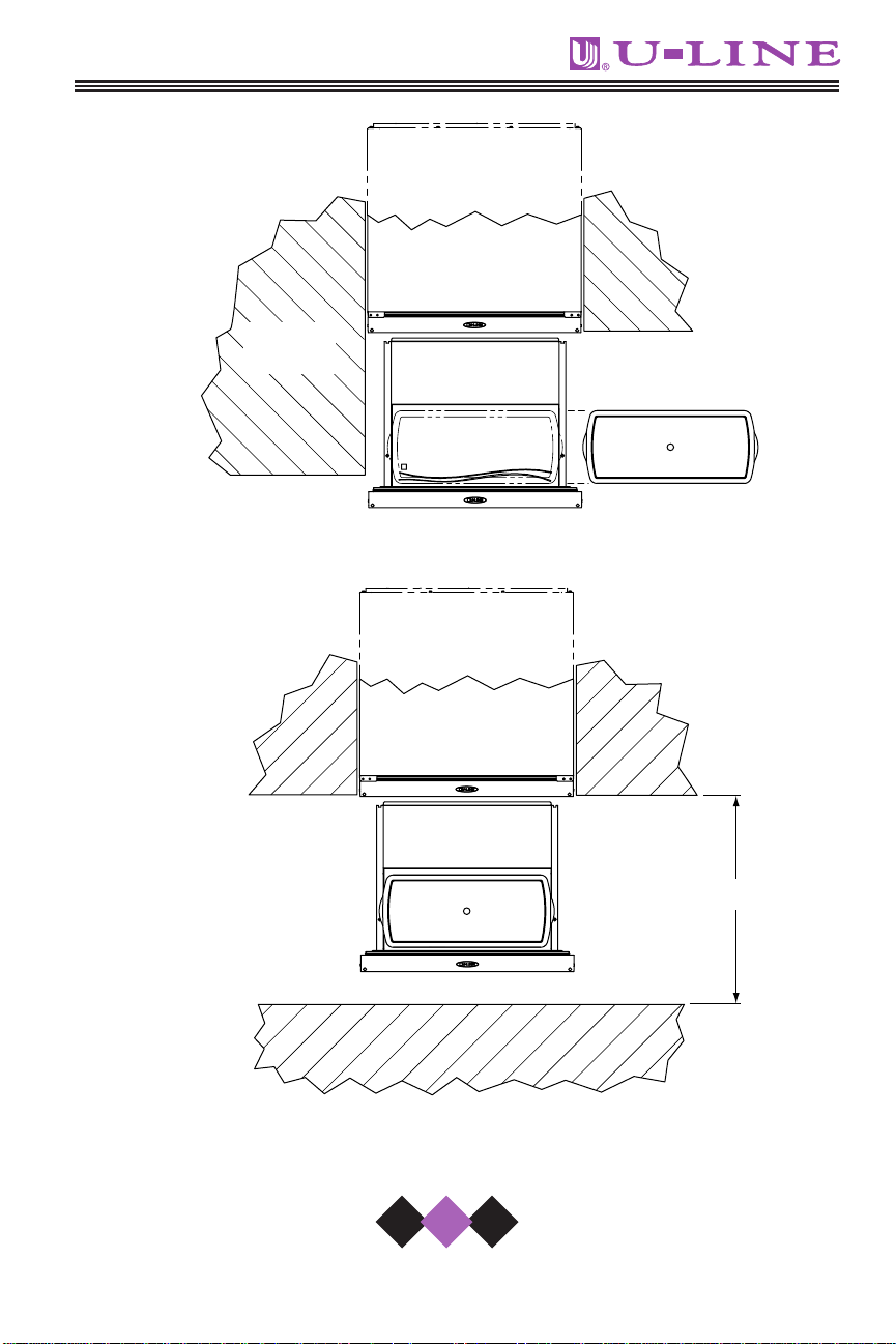
Figure 2 – Left wall installation
Figure 3 – Front Clearance
CABINET
7
OR WALL
DWR002
24" MIN.
DWR003
Page 10
4. Position the unit to allow free air flow through the front grille
(Figure 4).
Figure 4
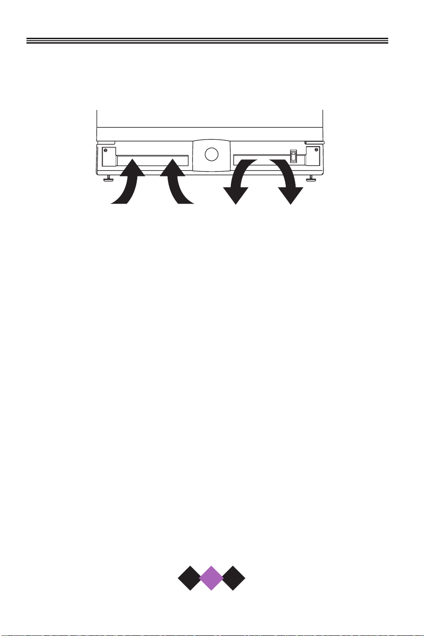
LEVELING THE UNIT
It is important that the unit is level. All Échelon™ Series units are
equipped with adjustable feet for leveling and height adjustment
(Figure 5).
To level the unit:
1. Adjust all four leveling feet evenly so that the top of the cabinet is at
the desired installation height.
2. Using a level of at least two feet in length, measure the level of the
floor where the unit is to be installed. Measure back-to-front and
side-to-side and note the measurements.
3. With the unit on a level surface, adjust no more than three of the
feet, as appropriate, to compensate for the floor level measurements noted in Step 2.
OFF
ON
DWR004
INTAKE
EXHAUST
User’s Manual
8
Page 11

4. Place the unit in position where it is to be installed. Re-check cabinet height and levelness (Figure 6) and adjust if necessary.
Figure 5
Figure 6
9
RAISE
LEVEL
TWO PLACES
LOWER
DWR005
DWR021
Page 12

10
User’s Manual
BUILT-IN INSTALLATION
Your U-Line product is designed for built-in installation only. When built-in,
it does not require additional air space for the top, sides, or rear.
However, the front grille must NOT be obstructed.
NOTE
To ease unit installation and removal, it is recommended that
the cabinet rough opening dimensions be increased by at
least 1/4" over the dimensions given for your unit.
Unit Dimensions
* For full overlay door panels, add 3/4".
Once the unit is leveled and placed into the wall or under a
cabinet, it is ready to be secured to the wall or cabinet with the anti-tip
system (Figure 7).
Follow the instructions included with the anti-tip kit.
The anti-tip kit must be installed on this unit before it is used.
Never use the drawers as steps or a shelf to support more
than the drawers’ content.
!
WARNING
Width Height Depth*
23-15/16" 34-1/8" 24"
Page 13

Figure 7
CUSTOM DRAWER PANELS
Two types of custom drawer panels can be installed on your
U-Line unit to harmonize with or accent the surrounding decor.
FULL OVERLAY DRAWER PANEL
Full overlay drawer panels completely cover the drawer frames and handle to give a built-in appearance. See Table 1 for full overlay drawer panel
dimensions (Figure 11, see page 13).
Table 1. Full Overlay Panel Dimensions
A
1
B
2
C
1
Top panel with 1/2
" gap
11-13/16" 14-3/4" 1"
between drawers
Top panel with 1/4" gap
12-1/16" 15" 1-1/4"
between drawers
All bottom panels 11-13/16" 14-3/4" 1"
1
Screw hole location
2
Overall panel height
COUNTER TOP
11
OR WALL
ANTI-TIP KIT
DWR010
Page 14

OVERLAY PANEL KIT PARTS
• The total weight of both drawer panels must not weigh
more than 20 lbs.
• The thickness of the drawer panel must be 3/4".
Remove existing drawer front from cabinet:
1. Open drawer. Pull door gasket
(Figure 8) out of the groove (top
edge of door only). Start in the middle and pull outward, moving
toward the edge. This may take
some force.
2. Remove the two screws located on
both sides of the lower handle.
Remove the handle (Figure 9).
3. Slide the existing drawer panel and
cardboard spacer out of the
drawer frame. Discard the spacer.
Attaching the full overlay panel:
4. If required, attach optional cabinet
handle hardware to the overlay panel
at this time. If an optional cabinet
handle is installed, make sure the
mounting screw heads are countersunk.
12
User’s Manual
1
Part Number Description Quantity
42120 Spacer Nylon 3/8 OD x .19 ID 10
42121 Screw #10 x 5/8 Round Head 10
Figure 9
Figure 8
HANDLE
SCREW
GASKET
DWR_OL_00
DWR_OL_002
Page 15

13
5. On a clean surface, place the wood panel face down and tape the
existing drawer panel (removed in step 3) on the back of the wood
panel (Figure 10) and drill the five (5) holes (5/32" drill 3/8" deep)
through the coated steel panel and 3/8" into the wood panel
according to the diagram (Figure 11). Remove tape from the drawer panel, and enlarge the five holes in the front panel using a .0201"
drill (#7) drill.
Figure 10
Figure 11
BACK OF
WOOD PANEL
NOTE:
For 1/2" gap between
top and bottom panels,
this dimension must be
11/32". For 1/4" gap, this
dimension must be 19/32"
for TOP PANEL ONLY.
SIDE OF
WOOD PANEL
TAPE
COATED STEEL
DRAWER PANEL
3/8" BOTH SIDES
BOTTOM OF
WOOD PANEL
DWR_OL_003
TOP OF WOOD PANEL
2-15/16"
A
C
1"
5/32" X 3/8" DEEP
5 PLACES
11-7/8"
23-3/4"
COATED STEEL
DRAWER PANEL
1"
DWR_OL_004
B
Page 16

User’s Manual
14
6. Attach the drawer panel to the wood panel using #10 x 5/8"
(P/N 42121) wood screws and nylon spacers (P/N 42120). The
nylon spacers fit between the wood panel and the drawer panel as
shown (Figure 12).
Figure 12
Drawer panel and wood panel must be aligned properly or
drawer will not operate correctly.
Assembling the drawer and wood panel:
7. Install the overlay panel by sliding the drawer panel back into the
drawer frame.
8. Replace the handle assembly and secure with the two screws
removed in Step 2.
9. Starting at the corners and working toward the center, push the
drawer gasket back into place.
COATED STEEL
TYPICAL
WOOD
PANEL
DRAWER PANEL
#10 X 5/8" ROUND
HEAD SCREW
FIVE REQUIRED
PLASTIC SPACER
FIVE REQUIRED
DWR_OL_005
Page 17

15
CUSTOM INSERT DRAWER PANEL
Custom drawer panels can be inserted into the drawer frames to match the
surrounding decor. Custom drawer panels
can be flat or raised, as long as the
maximum panel thickness where inserted
into the drawer reveal (channel) is 1/4"
thick. For raised panels, the depth of
the reveal is 1/4" on all four sides. See
Table 2 for custom drawer panel insert
dimensions (Figure 13).
Table 2. Custom Insert Drawer
Panel Dimensions
The total weight of both drawer panels or panel inserts
must not weigh more than 20 lbs.
2075DWRR DRAWER HANDLE OPTIONS
Black drawer models come from the factory, equipped to
be used with full overlay drawer panels. Please refer to
your user’s manual for instructions on preparing and
installing the full overlay drawer panels.
For all applications where full overlay drawer panels are
not used (examples are: custom 1/4 inch panel inserts,
or no panel at all - standard black finish), replacement
drawer handles MUST
be installed on each drawer. The
part number is 11926-4-BLK and can be purchased from
your U-Line dealer.
AB
12-15/16" 23-1/32"
Figure 13
B
A
A
DWR007
Page 18

Install the custom insert as follows:
Insert edges may be SHARP! Use care when installing.
1. Open drawer. Pull drawer gasket out of groove (top edge of
drawer only). Start in the middle and pull outward, moving
toward the edge (Figure 14).
This may take some force, be
careful.
2. Remove the three screws
behind the gasket. Carefully pull
the top handle up and off. You
may discard the top handle as
it will be replaced with the full
handle.
3. Remove the two outside
screws and the lower handle
(Figure 15).
4. Remove existing panel and
cardboard spacer. The panel
and spacer are no longer needed and may be discarded.
!
WARNING
User’s Manual
16
Figure 14
FULL HANDLE
STANDARD
HANDLE
Figure 15
FULL HANDLE SHOWN
DWR020
Page 19

5. Slide custom drawer panel insert into 1/4" channel in drawer front.
6. Attach the full handle to the lower handle using the 3 screws
removed in step 2.
7. Holding drawer gasket out of the way, replace handle on drawer
making sure it is seated properly on insert and that screw holes line
up.
8. Install two screws removed in step 3.
9. Starting at the corners and working inward, push drawer gasket into
place on the drawer.
INITIAL START-UP AND ADJUSTING
THE TEMPERATURE CONTROL
Once the installation is complete, the unit is ready for initial start-up and
operation.
1. Plug the appliance cord into a 115V polarized, grounded electrical
outlet.
The unit is turned ON with the ON/OFF switch in the front grille (Figure
16). (All units are shipped in the ON position.)
2. Wipe out inside of unit with a clean, water-dampened cloth.
Figure 16
17
OFF
ON
ON/OFF SWITCH
DWR011
Page 20

18
User’s Manual
TEMPERATURE CONTROLLER
Figure 17
The temperature controller (Figure 17) is located in the top
drawer. It consists of an LED display, two LED status indicator lights and
three touch pad buttons. The LED display shows the temperature set
point and is calibrated in degrees Fahrenheit. The controller is factory
programmed for a set point of 38°F which will show when the unit is first
powered-up.
To display actual temperature, press the “WARMER” button momentarily. A solid status indicator light (1, Figure 17) will show the air temperature reading in the cabinet for approximately 10 seconds.
To adjust the temperature set point, press the “SET TEMP”
button momentarily; the display will flash. Press the “WARMER” or
“COOLER” button as desired to change the set point. When the desired
set point shows on the display, wait 10 seconds and the new set point
will be saved. Wait 24 hours for the temperature to stabilize before
checking the actual temperature again.
Refer to Table 1 to determine indicator light status.
LED Status Indicates
1• Solid • Refrigerator Temperature displayed
• Flashing • Not Applicable
2• Flashing • Open Thermistor – call for service
Table 1. Indicator Light Status
TEMP
WARMER
COOLER
1 2
WARMER
COOLER
SET
TEMP
CLRCO011B
Page 21

19
DRAWERS
The drawers should only be removed for
servicing by a trained and certified repair
person.
TOP STORAGE BIN
Grasp the bin handle and slide backward to access the contents below
(Figure 18). The bin may be completely
removed for cleaning once it clears the
guides on each side of the drawer. If
heavy items are stored in bin, push
front of bin down slightly while sliding.
Slide bin forward, especially with heavy
items, to ensure that drawer closes
completely.
CRISPER
To access the crisper, open the bottom
drawer fully. Grasp the handle to either
side of the crisper and slide just enough
to access the contents (Figure 19). To
remove crisper, support both ends and
slide out completely. To remove the
glass crisper cover, remove the crisper
and push up on cover from bottom.
CAUTION
When opening or closing
the crisper, pull or push
slowly and carefully. If it is
pulled out too far or pushed
in too hard, it could come
out all the way and possibly
cause damage or injury.
DWR016
BIN GUIDE
Figure 18
DWR017
CRISPER
COVER
Figure 19
Page 22

20
User’s Manual
OPERATION
DRAWER ORGANIZER
Adjust the drawer organizer to compensate for different size
bottles or items. The organizer can be used in either drawer, but is
shipped from the factory in the top drawer.
The organizer may be adjusted
left-to-right or front-to-back as
required. When adjusting the
organizer, open the drawer
fully, remove all items, and
brace the drawer to prevent
movement. To adjust, turn the
drawer organizer knob (Figure
20) counter-clockwise to
loosen and use two hands to
position as desired. Tighten
knob after adjustment is made.
Do not over-tighten.
Clean the drawer organizer
with warm water and a mild
detergent only. Do not use solvent based or abrasive cleaners and do not place the drawer organizer in a dishwasher.
Figure 20
KNOB
DWR014
Page 23

21
Be sure that items stored in the rear
of the top drawer do not interfere
with the sliding operation of the storage bin (Figure 21). Tall items such
as milk jugs can be stored toward
the front of the drawer as long as
they do not interfere with the closing
of the drawer. Taller items can be
stored on their side in the storage
bin.
The storage bin is designed to
accommodate the storage of two
wine bottles, even when opened.
Place the bottle in the bin so that the
neck of the bottle rests on the front
lip of the bin.
Figure 21
STORAGE BIN
DWR015
Page 24

LIGHT BULB REPLACEMENT
Light bulb replacement in the Échelon™ series is simple.
1. Remove the light housing cover by
sliding the cover toward the tab,
swinging the end opposite the tab
down and pulling down and away
(Figure 22).
2. Replace bulb with genuine U-Line
#31317 replacement.
U-Line P/N 31317
Do not use any other replacement bulb than the one recommended.
3. Replace the light housing cover by inserting the tab FIRST, sliding the
cover toward the tab and pushing up the other end. You should hear
a snap/click.
!
WARNING
22
User’s Manual
Figure 22
1
2
TAB
UL305
3
Page 25

23
CLEANING & MAINTENANCE
Periodic cleaning and proper maintenance will ensure efficiency, top performance, and long life. The maintenance intervals listed are based on
normal conditions. You may want to shorten the intervals if you have
pets, the unit is used outdoors, or other special considerations.
EXTERIOR CLEANING — AS REQUIRED
The door, grille and cabinet may be cleaned with a mild detergent and
warm water solution. Do not use solvent based or abrasive cleaners.
Use a soft sponge and rinse with clean water. Wipe with a soft, clean
towel to prevent water spotting.
Stainless steel models can discolor when exposed to chlorine gas and
should be cleaned. Clean stainless steel models with a mild detergent
and warm water solution and a damp cloth. Never use abrasive cleaning
agents.
CAUTION
Stainless steel models exposed to chlorine gas and moisture,
such as areas with spas or swimming pools, may have some
discoloration of the stainless steel. Discoloration from chlorine gas is normal.
INTERIOR CLEANING — AS REQUIRED
1. Disconnect power to the unit.
2. Remove the crispers and the lower drawer crisper glass cover.
Clean the crispers and the glass with warm water and a mild
detergent only. Do not use solvent based or abrasive cleaners.
Do not place crispers or glass in a dishwasher.
3. Wipe down the interior with a solution of mild detergent and warm
water. Do not use solvent based or abrasive cleaners.
4. Rinse thoroughly with clear water.
Page 26

24
User’s Manual
5. Reconnect power to the unit.
• DO NOT use solvent cleaning agents or abrasives
on the interior. These cleansers may damage or
discolor the interior.
CONDENSER CLEANING - EVERY 3 MONTHS
Disconnect electric power to the unit before
cleaning the condenser.
To remove and replace the grille for access to the condenser fins
follow this procedure:
Figure 23
1. Remove the screws (Figure 23) at each end of the grille.
2. Remove the grille.
WARNING
!
WARNING
!
DWR019
Page 27

25
DO NOT touch the condenser fins. The condenser fins are
SHARP and can be easily damaged.
3. Clean the condenser coil using a soft brush with a “combing” action
or vacuum cleaner. Do not touch the condenser coil.
4. Position the grille to align the screw holes with the cabinet.
5. Insert the grille screws and tighten. Do not overtighten.
STORAGE
If the unit is to be stored or not used for extended periods:
1. Prop the drawers open at least two inches to allow for air circulation and prevent mold and mildew.
2. Disconnect unit from main electrical power source.
3. Leave power cord disconnected until ready to reuse.
!
WARNING
Page 28

26
User’s Manual
TROUBLESHOOTING
BEFORE CALLING FOR SERVICE
If the unit appears to be malfunctioning, read through NORMAL OPERATION first. If the problem persists, check the TROUBLESHOOTING GUIDE.
Locate the problem in the guide and refer to the cause and its remedy
before calling for service. The problem could be something very simple
which can be solved without a service call.
TROUBLESHOOTING GUIDE
ELECTROCUTION HAZARD
NEVER attempt to repair or perform maintenance on the unit until the main electrical
power has been disconnected.
Troubleshooting — What to check
when problems occur
Problem Possible Cause Remedy
No interior light. Loose or burned out Tighten or replace bulb.
bulb. See page 22 for light
replacement instructions.
The unit is not Light staying on. Call for service.
cold enough.
Item(s) interfering Reposition or remove item(s).
with drawer.
Dirty condenser coils. Clean condenser.
See page 24.
Airflow to front grille Airflow must not be
blocked. obstructed to front grille.
See INSTALLATION.
DANGER
! !
Page 29

27
Problem Possible Cause Remedy
The unit is not Temperature not set Set temperature controller to
cold enough cold enough. colder setting. See page 18.
(continued) Allow 24 hours for
temperature to stabilize.
Noise during Certain sounds Soft sounds from the
operation. are normal. compressor and fan motor
will be heard.
Fresh food Drawer not closed Be sure drawer is closed
section too correctly. correctly.
cold.
Temperature control Set temperature controller
set too cold. to warmer setting.
See page 18.
Drawer(s) Items too tall. Adjust items in drawer(s).
can’t close.
Temperature Open Thermistor. Call for service.
controller flashes.
IF SERVICE IS REQUIRED
If the need for service arises, contact the dealer from whom the unit was
purchased. State the Model Number and Serial Number and explain the
problem. The Model and Serial Number plate is located inside unit at
upper right hand corner; you must pull the top drawer out completely to
see the serial number plate.
If you do not know the name of the selling dealer or local service company, you can check on-line at www.U-LineService.com.
REPLACEMENT PARTS
Use only genuine U-Line replacement parts. Genuine U-Line parts are
designed to work correctly with U-Line products and offer superior
service life. The use of non-U-Line parts can damage the unit and may
void the warranty.
Page 30

28
User’s Manual
Page 31

P .O. Box 245040
Milwaukee, WI 53224-9540
P hone: 414.354.0300
F ax: 414.354.7905
www.u-line.com
Printed in U.S.A. P/N 30001 (Rev. 5/03)
 Loading...