

Page 1
IV/005/667
Page 2
Page 3
Page 4
Technische Daten:
Technical Specifications:
Spurlage
Bandgeschwindigkeiten
(umschaltbar)
max. Spulengröße
Frequenzumfang
(DIN 45511)
Fremdspannungsabstand
19,05 cm/s
Gleichlaufabweichung
bei 19,05 cm/s
Klirrfaktor
Nachbarkanaldämpfung 50 db
Eingänge
Ausgänge
Internationale Vierspur
2,38 cm/s;
9,53 cm/s;
18 cm Durchmesser
50— 4 000 Hz ( 2,38 cm/s)
50— 9 000 Hz ( 4,75 cm/s)
50—16 000 Hz ( 9,53 cm/s)
50—20000 Hz (19,05 cm/s)
50 db
±0,15% (gehörrichtig)
max. 5%
hochohmiger Ausgang
Mikro: 0,15 mV/2 kOhm
Radio: 5mV/50kOhm
Phono: 350 mV/1 Megohm
0,75 V/4,7 kOhm,
3 V/4 Ohm
4,75 cm/s
19,05 cm/s
Recording Sense
Tape Speeds
Reel Diameter
Frequency Response
(according to German
Standard DIN 45511)
Signal-to-Noise-Ratio
(at 7 1/2 ips)
Wow and Flutter
at 7 1/2 ips
Harmonic Distortion
Channel Separation
Inputs
Outputs
Four tracks to international
standards
15/16 ips, 1 7/8 ips,
3 3/4 ips, 7 1/2 ips
up to 7"
50— 4,000 cps at 15/16 ips
50— 9,000 cps at 1 7/8 ips
50—16,000 cps at 3 3/4 ips
50—20,000 cps at 7 1/2 ips
50 db
±0,15%
5 % max. across the
high-impendance output
50 db
Micro 0.15 mV/2 kiloohms
Radio 5 mV/50 kiloohms
Phono 350 mV/1 megohm
0.75 V/4.7 kohms
3 V/4 ohms
Page 5
Reglereinstellungen
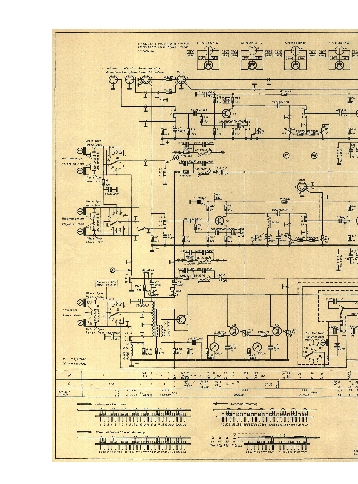
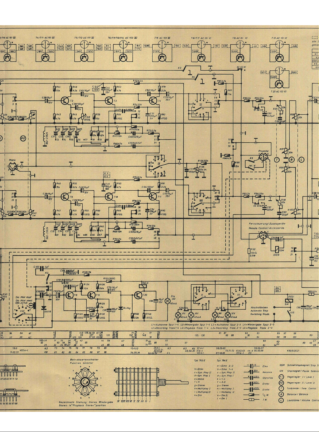
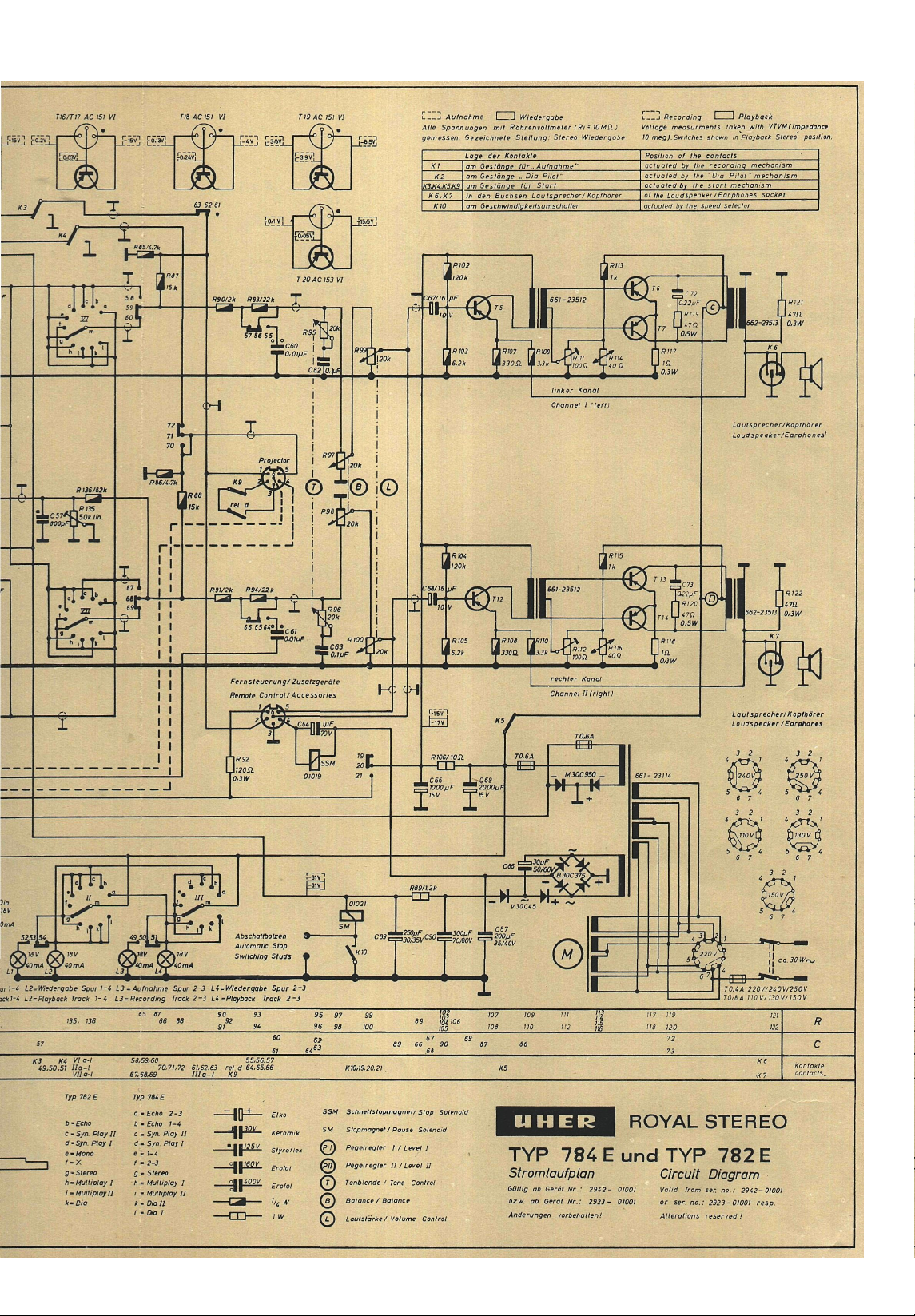
Vor Einstellung aller Regler prüfen, ob die Spannungen an R 89 und R 106 mit den auf dem Schaltbild
angegebenen Werten übereinstimmen. Die Einstellung der Regler ist in untenstehender Reihenfolge
vorzunehmen.
R 149 Gegenkopplung Transistor T2: Tongenerator an die Kontakte 4 und 2 der Buchse „Radio" anschließen und 10 mV/1000 Hz einspeisen. NF-Millivoltmeter an den Kontakt 5 der Buchse „Projektor"
und an Kontakt 2 der Buchse „Phono" anschließen. Gerät auf „Stereo-Aufnahme" schalten. Regler
Pegel II auf linken Anschlag stellen. Regler Pegel I so einstellen, daß NF-Millivoltmeter 0,85 V anzeigt.
Regler Pegel I nicht verändern. Tongenerator an die Kontakte 1 und 2 der Buchse „Radio" anschießen
und 10 mV/1000 Hz einspeisen. NF-Millivoltmeter an den Kontakt 1 der Buchse „Projektor" und an
Kontakt 2 der Buchse „Phono" anschließen. Regler R149 so einstellen, daß NF-Millivoltmeter 0,85 V
anzeigt.
R139,R143 Aussteuerungsanzeiger: Meßanordnung wie unter „R 149GegenkopplungTransistorT2" beschrieben. Bei einer NF-Spannung von 0,85 V an den Kontakten 5 bzw. 1 der Buchse „Projektor" und
Kontakt 2 der Buchse „Phono" wird der Zeiger des betreffenden Aussteuerungsinstrumentes auf die
Marke zwischen dem schwarzen und roten Feld eingestellt.
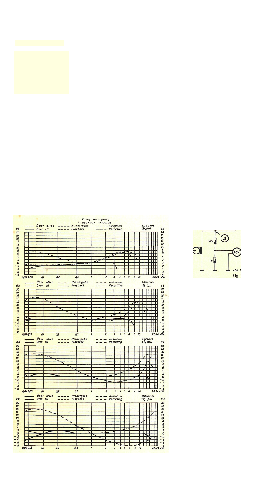
R3/R8 HF-Vormagnetisierung: Die HF-Vormagnetisierung beeinflußt den Frequenzgang des Gerätes.
Die unten angegebene Spannung ist ein Mittelwert; die endgültige Einstellung erfolgt nach der Kontrolle
des Frequenzganges. Gerät auf „Stereo-Aufnahme" schalten. NF-Röhrenvoltmeter gemäß Abb. 1 an das
obere bzw. untere System des Aufnahmekopfes über einen Spannungsteiler (100kOhm + 1 kOhm) in
den Punkten A anschließen. Mit R8 wird für Kanal I, mit R3 für Kanal II am Röhrenvoltmeter eine
Spannung von 280 mV eingestellt.
R 28, R 29 Gegenkopplung Transistor T8: Tongenerator an die Kontakte 1 und 2 bzw. 4 und 2 der Buchse
„Radio" anschließen und 10 mV/1000 Hz einspeisen. Gerät auf „Stereo-Aufnahme" schalten. NF-Millivoltmeter an die Kontakte 1 bzw. 5 der Buchse „Projektor" und an Kontakt 2 der Buchse „Phono" anschließen. Regler „Pegel II" auf linken Anschlag stellen. Regler „Pegel I" so einstellen, daß Millivoltmeter 0,85 V anzeigt. Band einlegen und das Signal des Tongenerators aufnehmen. Gerät auf StereoWiedergabe schalten und mit R 28 bzw. R 29 den Wiedergabepegel beider Kanäle auf 0,75V einstellen.
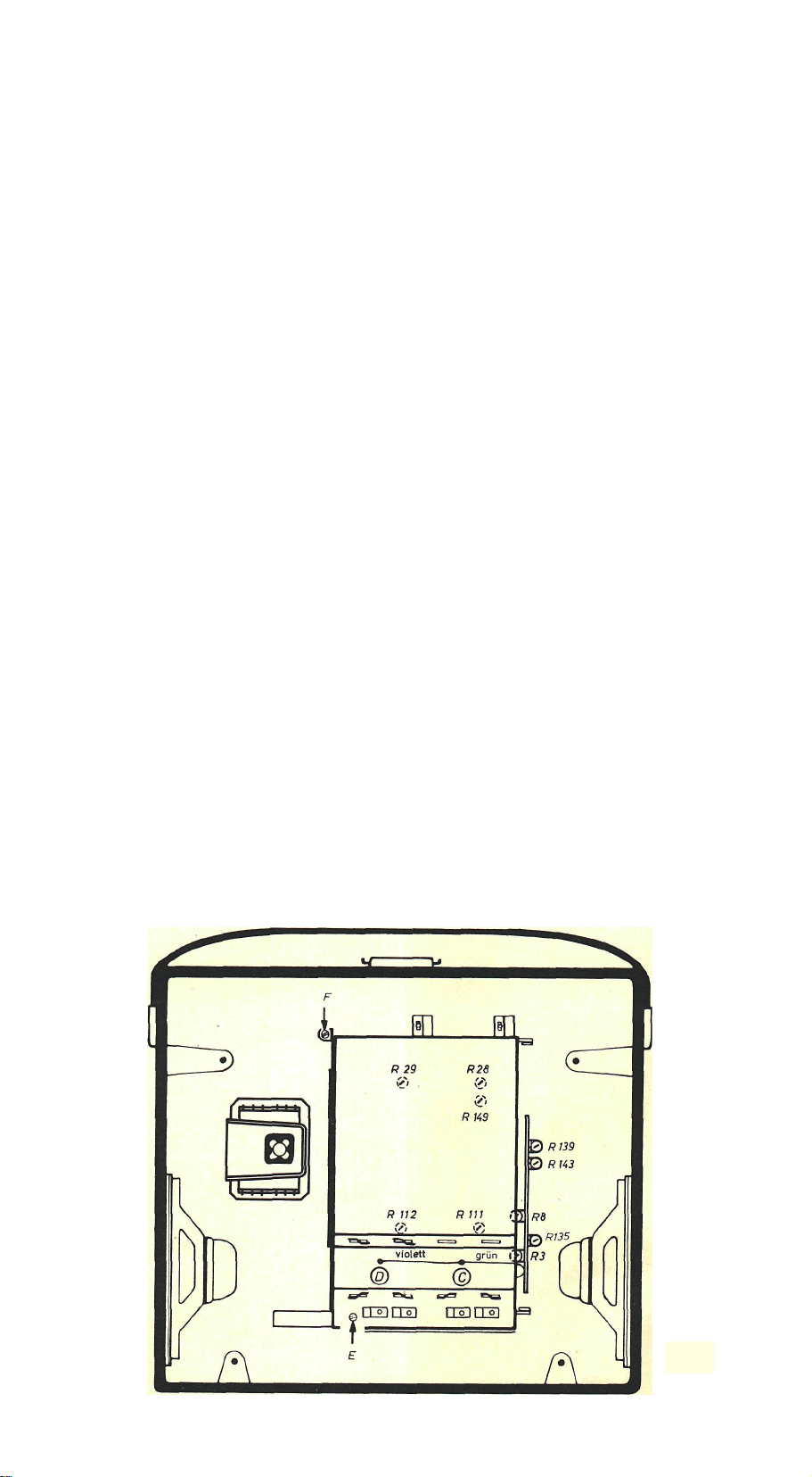
R 111/R 112: Arbeitspunkt der Gegentakt-Endstufen T6, T7/T13, T14 (s. Abb. 2). Taste „Start" drücken.
Regler „Lautstärke" auf 0 stellen. Drahtbrücke (violett) zwischen den Punkten C und D entfernen. Zuführung (grün) zu Punkt C ablösen und Milliamperemeter (Meßbereich 60 mA, Ri = 5Ohm), zwischen
Zuleitung (grün) und Punkt C schalten. Mit R 111 einen Strom von 22 mA einstellen. Sinngemäß
erfolgt die Einstellung des R 112, dazu ist das Milliamperemeter zwischen Zuleitung (grün) und Punkt
D zu schalten und ein Strom von 22 mA einzustellen. Anschließend Drahtbrücke und Zuleitung an die
Punkte C und D wieder anlöten.
R 135 Überspielpegel Multiplay: Tongenerator an die Kontakte 1 und 2 der Buchse „Radio" anschließen
und 10 mV/1000 Hz einspeisen. Gerät auf „Multiplay I" schalten. NF-Millivoltmeter an den Kontakt 1
der Buchse „Projektor" und an Kontakt 2 der Buchse „Phono" anschließen. Regler „Pegel II" auf linken
Anschlag stellen. Regler „Pegel I" so einstellen, daß das NF-Röhrenvoltmeter 0,85Volt anzeigt.Tonband
einlegen und das Signal des Tongenerators aufnehmen. Gerät auf „Multiplay II" schalten und Tonband
zurückspulen. Regler „Pegel I" auf linken Anschlag stellen. Regler „Pegel II" auf rechten Anschlag
stellen. Tonbandgerät auf Aufnahme schalten und starten. Mit R135 am NF-Röhrenvoltmeter 1 V einstellen.
Abklappen der Verstärker (s. Abb. 2): Nach Entfernen der Schrauben E und F kann der Verstärker
abgeklappt werden.
Umstellen auf 60-Hz-Betrieb: Zur Umstellung auf 60 Hz bzw. 50 Hz ist die Motorrolle auszuwechseln.
Abb. 2
Fig. 2
Page 6

Adjustment of Variable Resistors
Before adjusting any variable resistor check for proper voltages at R 89 and R 106 as given on the circuit
diagram. The variable resistors must be adjusted in the order given below.
R149 Inverse Feedback of stage T2: Connect an audio oscillator across the contacts 4 and 2 of the
"Radio" socket and feed a signal of 1,000 cps and 10 millivolts. Connect an audio-frequency millivoltmeter to contact 5 of the socket marked "Projector" and contact 2 of the "Phono" socket. Set the
recorder for stereo recording. Set the control "Level II" at its extreme anticlockwise position. Then
adjust the control "Level I" so that the connected millivoltmeter reads 0.85 volts. Do not vary the
setting of the control "Level I". Connect an audio oscillator across the contacts 1 and 2 of the "Radio"
socket and feed a signal of 1,000 cps and 10 millivolts. Connect an audio-frequency millivoltmeter to
contact 1 of the "Projector" socket and contact 2 of the "Phono" socket. Adjust R149 so that the connected millivoltmeter reads 0.85 volts.
R139, R 143 Recording Level Indication: Set up the measuring circuit as described in the paragraph
"R 149 Inverse Feedback of stage T2". When the audio signal across the contacts 5 or 1 respectively
of the "Projector" socket and contact 2 of the "Phono" socket has a voltage of 0.85 volts, adjust the
VU-meter so that its pointer stands on the mark between the black and red bands of the scale.
R 3, R 8 Bias: The adjustment of the bias will influence the frequency response of the recorder. The
voltage given below is an average; the final adjustment is made after having checked the frequency
response. Set the recorder for stereo recording. Connect an audio-frequency vacuum tube voltmeter
according to Fig. 1 to the upper and lower system respectively of the recording head (at the points A
respectively) by means of a voltage divider (100 kiloohms + 1 kiloohm). Adjust a VTVM reading of
280 millivolts by means of R 8 (for channel I) and R3 (for channel II) respectively.
R 28, R 29 Inverse Feedback of the stages T8: Connect an audio oscillator to the contacts 1 and 2 and 4
and 2 respectively of the "Radio" socket and feed a signal of 1,000 cps and 10 millivolts. Set the
recorder for stereo recording operation. Connect an audio-frequency millivoltmeter across the contacts
1 or 5 respectively of the "Projector" socket and contact 2 of the "Phono" socket. Turn the control
"Level II" to its extreme anticlockwise position. Adjust the control "Level I" so that the millivoltmeter
reads 0.85 volts. Thread the tape and record the feeded signal. Set the recorder for stereo playback
operation and adjust, by means of R 28 and R 29, the levels of channel I and channel II so that the
connected millivoltmeter reads a voltage of 0.75 volts.
R 111, R 112: Bias Voltages of the Push-Pull Power Stages T6, T7 and T13, T14 (see Fig. 2). Depress
the start key and set the volume control at zero position. Remove the violet wire which bridges the
points C and D. Unsolder the green wire from point C and connect a milliammeter with a range of
60 milliamperes and a resistance of 5 ohms between the green wire and point C. Set R111 for a meter
reading of 22 mA. The adjustment of R 112 is made in the same manner. For this purpose the milliammeter must be connected between the green wire and point D. Then a current of 22 mA must be adjusted by means of R 112. Thereafter return the bridging wire and the green wire to points C and D.
R 135 Multi-Play Transfer Level: Connect an audio oscillator to the contacts 1 and 2 of the "Radio"
socket and feed a signal of 1,000 cps and 10 millivolts. Set the recorder for "Multiplay I" operation.
Connect an audio-frequency millivoltmeter across the contact 1 of the "Projector" socket and contact 2
of the "Phono" socket. Turn the control "Level II" to its extreme anticlockwise position. Adjuste the
control "Level I" so that the millivoltmeter reads 0.85 volts. Thread the tape and record the feed signal.
Rewind the tape and set the recorder for "Multiplay II" operation. Turn the control "Level I" to its
extreme anticlockwise position. Turn the control "Level II" to its extreme clockwise position. Set the
recorder for start and recording operation. Adjust R135 so that the VTVM reads 1 volts.
Hinging Out the Amplifier (see Fig. 2): The amplifier can be hinged out after screws E and F have
been removed.
Conversion for 60-cps Mains Supply: In order to adjust the recorder for 60-cps or 50-cps mains supply,
the motor pulley must be replaced.
 Loading...