

Page 1
H
CADDY 5 UL
CADDY 10 UL
ENGLIS
OPERATOR’S MANUAL
Page 2
CADDY
1 TECHNICAL CHARACTERISTICS
5/2
Transparent removable bowls n 1 2 2 3 4
Capacity of each bowl,
approx.
Dimensions:
width cm 23 47 23 35 47
depth cm 34 34 34 34 34
height cm 58 58 58 58 58
Net weight, approx. kg 16 26 17 21 26
Gross weight, approx. kg 17 29 19 24 29
Adjustable thermostats n 1 2 1 1 2
Hermetic compressor
Air-cooled condenser
Overload protector
Noise level lower than 70 dB (A)
10/1
l 10 10 5 5 5
5/3
10/2
IMPORTANT
Read electrical ratings written on the data
plate under the individual units. The serial
number of the unit is preceded by the
symbol #. Data plate specifications will
always supersede the information in this
manual.
Specifications are subject to change without
notice.
2 INTRODUCTION
Please read all sections of this manual
thoroughly to familiarize yourself with all
aspects of the unit.
Like all mechanical products, this machine will
require cleaning and maintenance. Besides,
dispenser working can be compromised by
operator’s mistakes during disassembly and
cleaning. It is strongly recommended that
personnel responsible for the equipment’s daily
operations, disassembly, cleaning, sanitizing
and assembly, go through these procedures in
order to be properly trained and to make sure
that no misunderstandings exist.
3 INSTALLATION
1 - Remove the corrugate container and
packing materials and keep them for
possible future use.
2 - Inspect the uncrated unit for any possible
damage. If damage is found, call the
delivering carrier immediately to file a
claim.
3 - Install the unit on a counter top that will
support the combined weight of dispenser
and product.
4 - A minimum of 15 cm (6”) of free air space
all around the unit should be allowed to
5/4
guarantee adequate ventilation.
5 - Ensure that the legs are screwed tightly
into the base of the machine.
6 - In case of units with gravity faucet, install it
according to this handbook instructions
(chapter 5.3.4 ASSEMBLY).
7 - Before plugging the unit in, check if the
voltage is the same as that indicated on
the data plate. Plug the unit into a
grounded, protected single phase electrical
supply according to the applicable
electrical codes and the specifications of
your machine. When the unit has no plug,
install a proper grounded plug, in
compliance with electrical codes in force in
your area, suitable to at least 10 Amp
250 Volt (220-230 Volts 50-60 Hz areas)
and 20 Amp 250 Volt (100-115 Volts 5060 Hz areas) applications. Should you
prefer to connect the unit directly to the
mains, connect the supply cord to a 2-pole
wall breaker, whose contact opening is at
least 3 mm. Do not use extension cords.
ATTENTION
Failure to provide proper electrical ground
according to applicable electrical codes could
result in serious shock hazard.
8 - The unit doesn’t come presanitized from
the factory. Before serving products, the
dispenser must be disassembled, cleaned
and sanitized according to this handbook
instructions (chapter
5.3 CLEANING AND SANITAZING
PROCEDURES).
4 TO OPERATE SAFELY
1 - Do not operate the dispenser without
reading this operator’s manual.
2 - Do not operate the dispenser unless it is
properly grounded.
3 - Do not use extension cords to connect the
dispenser.
4 - Do not operate the dispenser unless all
panels are restrained with screws.
5 - Do not obstruct air intake and discharge
openings: 15 cm (6”) minimum air space all
around the dispenser.
6 - Do not put objects or fingers in panels
louvers and faucet outlet.
7 - Do not remove bowls, augers and mixers
for cleaning or routine maintenance unless
the dispenser is disconnected from its
power source.
2
Ugolini S.p.A.
Page 3
CADDY
5 OPERATING PROCEDURES
1 - Clean and sanitize the unit according to
the instructions in this manual. See chapter
5.3 CLEANING AND SANITIZING
PROCEDURES.
2 - Fill the bowls with product to the maximum
level mark. Do not overfill.
The exact quantity of product (expressed
as liters and gallons) is shown by marks on
the bowl.
3 - In case of products to be diluted with
water, pour water into bowl first, then add
correct quantity of product. In case of
natural squashes, it is advisable to strain
them, in order to prevent pulps from
obstructing the faucet outlet.
4 - Install the covers and check that they are
correctly placed over the bowls.
5 - Set the control switches as shown in
chapter 5.1 DESCRIPTION OF
CONTROLS.
6 - The dispenser must always run with the
covers installed to prevent a possible
contamination of the product.
7 - Always leave the dispenser on, as the
refrigeration stops automatically when the
beverage reaches the dispensing
temperature. The mixing devices will
continue to turn.
8 - To maintain a high standard of flavour,
keep refrigeration and mixing devices on
during the night when beverage is in the
bowl.
5. 1 DESCRIPTION OF CONTROLS
The dispenser is equipped with the power
switch only. When it is set to position I, the
power is turned on both to mixing devices and
to refregeration.
IMPORTANT
Should despenser be operated without using
all the bowls (left bowl, facing the unit from
dispensing side, must be always used) it is
advisable to remove (see 5.3.1 DISASSEMBLY
paragraph) the pump impeller from the empty
bowls.
If operated without liquid, the impeller would
be seriously damaged.
Beverage temperature adjustment (model
10/1 only): turn the knob, located on the right of
the faucet side of the dispenser, toward right to
decrease temperature or vicevarsa.
increase productivity, it is advisable to prechill the product to be used in the
dispenser.
3 - To shorten product cooling down time and
increase productivity, the bowl should be
refilled after the product level drops lower
than half and at the start of each day.
4 - The dispenser must be able to emit heat.
In case it seems excessive, check that no
heating source is close to the unit and air
flow through the slotted panels is not
obstructed by wall or boxes. Allow at least
15 cm (6”) of free clearance all around the
dispenser.
In any case if the product in the bowls is
cold the unit is running properly.
5. 3 CLEANING AND SANITIZING
PROCEDURES
Cleaning and sanitizing of the dispenser are
recommended to guarantee the conservation of
the best product taste and the highest unit
efficiency. This section is a procedural
guideline only and is subject to the
requirements of the local Health Authorities.
Prior to the disassembly and cleaning, the
machine must be emptied of product.
5. 3. 1 DISASSEMBLY
ATTENTION
Before any disassembly and/or cleaning
procedure make sure that the dispenser is
disconnected from its power source by
unplugging it or switching off the 2-pole wall
breaker.
1 - Remove cover from the bowl.
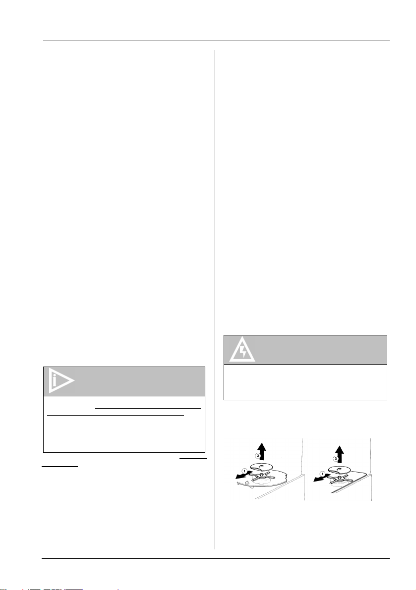
2 - Uncouple (1) the pump cover retainer and
lift it up and out (2) (see figure 1).
5. 2 HELPFUL HINTS
1 - The length of time for cooling down the
product is governed by many variables,
such as ambient temperature and
beverage initial temperature.
2 - To shorten product cooling down time and
Ugolini S.p.A.
figure 1
3 - Remove the pump cover.
4 - Remove the empty bowl by lifting first its
rear side (opposite to faucet side) up
3
Page 4

CADDY
and off bowl gasket (see figure 2).
5 - Remove the bowl gasket.
6 - Remove the pump impeller from its
location.
7 - Pinch tube faucet: push the dispensing
handle (1) and take the pinch tube off from
its seat (2) (see figure 3).
8 - Gravity faucet: extract the piston (1) and
then remove the dispensing handle (2-3)
(see figure 4).
9 - Slide drip tray out and empty it.
figure 2
figure 3
figure 4
5. 3. 2 CLEANING
ATTENTION
Before any disassembly and/or cleaning
procedure make sure that the dispenser is
disconnected from its power source by
unplugging it or switching off the 2-pole wall
breaker.
IMPORTANT
Do not attempt to wash any machine
components in a dishwasher.
1 - Prepare at least two gallons of a mild
cleaning solution of warm (45-60 °C 120140 °F) potable water and dishwashing
detergent. Do not use abrasive detergent.
Important: if present, follow label
directions, as too strong a solution can
cause parts damage, while too mild a
solution will not provide adequate cleaning.
IMPORTANT
In order to prevent any damages to the
dispenser use only a detergent suitable with
plastics parts.
2 - Using a brush, suitable for the purpose,
thoroughly clean all disassembled parts in
the cleaning solution.
ATTENTION
When cleaning the machine, do not allow
excessive amounts of water around the
electrically operated components of the unit.
Electrical shock or damage to the machine
may result.
3 - Rinse all cleaned parts with cool clean
water.
5. 3. 3 SANITIZING
Sanitizing should be performed immediately
prior to starting the machine. Do not allow the
unit to sit for extended periods of time after
sanitization.
1 - Wash hands with a suitable antibacterial
soap.
2 - Prepare at least two gallons of a warm (45-
60 °C 120-140 °F) sanitizing solution (100
PPM available chlorine concentration or 1
spoon of sodium hypoclorite diluted with
half a gallon of water) according to your
local Health Codes and manufacturer’s
specifications.
3 - Place the parts in the sanitizing solution
following manifacture ‘s specifications
(about five minutes).
4 - Place the sanitized parts on a clean dry
surface to air dry.
5 - Wipe clean all exterior surfaces of the unit.
Do not use abrasive cleaner.
5. 3. 4 ASSEMBLY
1 - Slide the drip tray into place.
2 - Pinch tube faucet: push the dispensing
handle (1) and insert the pinch tube into its
vertical seat in the bowl bottom(2). Lightly
pull the pinch tube end downwards til itl is
4
Ugolini S.p.A.
Page 5

CADDY
well arranged (3) (see figure 5).
3 - Gravity faucet: install the faucet handle
(1-2) and the piston with its gasket (3) (see
figure 6).
4 - Fit the bowl gasket to the evaporator. Note:
the largest brim of the gasket must face
against the drip plate (see figure 8).
figure 5
figure 6
sanitizer from the bowl(s). Drain this
solution. Do not rinse out the machine.
5. 4 IN-PLACE SANITIZATION
The In-Place Sanitization prior to starting
the machine may be performed, if needed,
only as further precaution, in addition to the
Disassembled Parts Sanitization described
before, but never in lieu of it.
1 - Prepare two gallons of a warm (45-60°C,
120-140 °F) sanitizing solution (100 PPM
available chlorine concentration or 1 spoon
of sodium hypoclorite diluted with half a
gallon of water) according to your local
Health Codes and manufacturer’s
specifications.
2 - Pour the solution into the bowl(s).
3 - Using a brush suitable for the purpose,
wipe the solution on all surfaces protruding
above the solution-level and on the
underside of the top cover(s).
4 - Install the top cover(s) and operate the
unit. Allow the solution to agitate for about
two minutes. Drain the solution out of the
bowl(s).
5 - Use fresh product to chase any remaining
sanitizer from the bowl(s). Drain this
solution. Do not rinse out the machine.
6 ROUTINE MAINTENANCE
5 - Place bowl on the unit. Wet the gasket for
ease of insertion.
CADDY 5 : be sure first that the faucet top
(1) is under the tooth jutting (2) out of the
drip plate (see figure 8).
6 - Replace the pump impeller and its cover
and hook the retainer.
7 - Use fresh product to chase any remaining
figure 7
figure 8
Ugolini S.p.A.
Daily: inspect the machine for signs of product
leaks past seals and gaskets. If proper
assembly does not stop leaks around seals or
gaskets, check for improper lubrication, worn or
damaged parts. Replace parts as needed with
original spare parts from the supplier.
6. 1 MAINTENANCE (TO BE
CARRIED OUT BY QUALIFIED
SERVICE PERSONNEL ONLY)
Montly: clean all internal components,
primarily the condenser, using compressed air.
To clean these internal parts, unplug the unit or
switch off the 2-pole wall breaker, then remove
front panel (dispensing side).
Condenser fins are very sharp. Use extreme caution
when cleaning.
5
Page 6

2441 V 2.0 01D17
1 Switch
2 Thermostat
3 Compressor
4Fan/Pump motor
21 22081-00001 Bowl gasket
✻✻✻ Please order what printed on piece
22 33800-05401 Impeller for 7 lt bowl
23 22800-19900 Central pivot
24 22040-00000 Central pivot OR
25 10554-45000 Clip
26 21087-00001 Thermostat
27 22800-18301 Cabinet for Caddy 7/1 -10/1
27 22800-18321 Cabinet for Caddy 10/2
28 22800-10000 Leg
29 22800-05500 Terminal block with cable clamp
30 22800-20700 Fan
31 01702-00000 Faucet cover for pinch tube faucet
31 22800-04410 Faucet cover for gravity faucet
33 33800-08900 Faucet assembly
34 33800-05402 Impeller for 10 lt bowl
35 22800-21900 Faucet piston
36 10028-02500 Faucet gasket
37 22800-04410 Faucet cover
38 22800-02303 Push handle
WIRING DIAGRAM
1 21980-00000 Cover
2 21703-00000 Pinch tube
3 22800-18730 10 lt bowl
4 21705-00000 Faucet spring
5 21704-00000 Rubber spring retainer
6 21701-00001 Push handle
7 21983-00000 Pump cover fixing clip
8 33800-05700 Evaporator assembly
9 21125-00000 Switch
10 22800-05100 Switch cap
11 22800-19300 Thermostat knob
12 33800-00803 Magnet
13 22800-04800 Motor bracket
14 22800-18901 Fan/pump motor
15 ✻✻✻ Relay
16 ✻✻✻ Overload protector
17 22800-18400 Caddy 7/1-10/1 dispensing side panel
17 22800-18420 Caddy 10/2 dispensing side panel
18 22800-00500 Drip tray cover
19 22800-00600 Drip tray (grey)
20 22800-18800 Pump cover
CADDY 10 U/UL
SPARE PART LIST
Page 7

2441 V 2.0 01D17
( ) For Caddy 5/3 only
✻✻✻ Please order what printed on piece
21 22800-18810 Pump cover
22 33800-05615 Bowl and faucet asbly for pinch tube faucet
22 33800-05617 Bowl and faucet asbly for gravity faucet
23 22800-17200 Bowl gasket
24 33800-05401 Pump impeller
25 22800-19900 Central pivot
26 22040-00000 Central pivot OR
27 21983-00000 Pump cover retainer
28 10554-45000 Clip
29 22800-18301 Cabinet for Caddy 5/2
29 22800-18311 Cabinet for Caddy 5/3
29 22800-18321 Cabinet for Caddy 5/4
30 22800-10000 Rubber leg
31 22800-05500 Terminal block with cable clamp
34 22800-21900 Faucet piston
35 10028-02500 Faucet gasket
36 22800-04410 Faucet cover
(32) 33800-00803 Motor magnet for Caddy 5/3
37 22800-02303 Push handle
(33) 22800-04706 Pump motor for Caddy 5/3
1Switch
2Thermostat
3 Compressor
4 Fan/Pump motor
5Pump
WIRING DIAGRAM
1 21703-00000 Pinch tube
2 21705-00000 Faucet spring
3 21704-00000 Spring holder
4 01701-00001 Push handle
5 33800-05710 Evaporator assembly
6 21125-00000 Switch
7 22800-05100 Switch cap
8 21087-00000 Thermostat
9 33800-00811 Pulley, magnet an d spacer asbly
10 22800-01800 Belt
11 22800-02201 Driving pulley
12 22800-04800 Motor bracket
13 22800-18911 Fan/pump motor
14 22800-20700 Fan
15 ✻✻✻ Relay
16 ✻✻✻ Overload protector
17 22800-18400 Caddy 5/2 dispensing side panel
17 22800-18410 Caddy 5/3 dispensing side panel
17 22800-18420 Caddy 5/4 dispensing side panel
18 22800-00500 Caddy 5/2, 5/4 drip tray cover
18 22800-00510 Caddy 5/3 drip tray cover
19 22800-00600 Caddy 5/2, 5/4 drip tray
19 22800-00610 Caddy 5/3 drip tray
(5) 33800-05762 Evaporator assembly Caddy 5/3
20 22800-09110 Bowl cover
CADDY 5 U/UL
SPARE PARTS LIST
Page 8

Ugolini S.p.A.
via dei Pioppi, 33
20090 Opera MILANO ITALY
www.ugolinispa.com
tel ++39 2 5300591
fax ++39 2 530059260
E-mail: sales@ugolinispa.com
2441_02 R3.0 02A09
 Loading...