

Ugolini ARCTIC COMPACT, ARCTIC DELUXE Service Manual
SERVICE MANUAL
ARCTIC DELUXE
ARCTIC COMPACT

2
ARCTIC COMPACT & DELUXE
3
SERVICE MANUAL
4
USER MANUAL
10
TROUBLE SHOOTING
16
4
ARCTIC COMPACT & DELUXE
1 INTRODUCTION
Like all mechanical products, this machine will require cleaning
and maintenance.
This Service Manual contains maintenance guideline s
dedicated to qualified service personnel only.
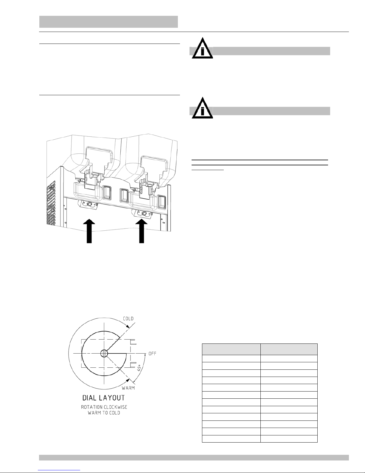
2 TEMPERATURE CONTROLS
All the units with12 or 20 litres bowls, both Deluxe and Compact
series, are equipped with one adjustable thermostat for each
bowl. The thermostats are located behind the panel under each
bowl (see figure 1).
figure 1
It is possible to adjust temperature between 6 °C and 12 °C. On
new machines the temperature is factory preset approx at 8°C.
For temperature adjustment proceed as follows:
- to decrease temperature: rotate the setting screw clockwise.
- to increase temperature: rotate the setting screw
counterclockwise (see figure 2).
figure 2
For Artic Compact 5 and 8 series the situation is the following:
Arctic Compact 5-8/1 are equipped with one thermostat to
control the themperature of the bowl.
Arctic Compact 5-8/2 are equipped only with one thermostat to
control the temperature of the bowl at the right.
Arctic Compact 5-8/3 are equipped only with one thermostat to
control the temperature of the central bow l .
Arctic Compact 5-8/4 are equipped with two thermostats to
control the temperature of the first and the third bowl from right.
The thermostats are always located behind the faucet side
panel under the coresponding bowl.
This means that the refrigeration on and off depend from the
setting of the temperature only of the bowls equipped with the
thermostats.
It is possible to set the temperature between 6 °C and 12 °C. On
new machines the temperature is factory preset approx at 8°C.
For temperature adjustment proceed as follows:
- to decrease temperature: rotate the setting screw clockwise.
- to increase temperature: rotate the setting screw
counterclockwise (see figure 2)
Independent temperature setting for each bowl is not possible.
The following table summarizes the number of thermostats
present on each model:
IMPORTANT
Rotating the setting screw of the thermostats co mple te ly
counterclockwise it is possible to switch off the
thermostat itself. This will stop the refrigeration only on
single bowl units. On multiple bowls units it is necessary
to switch all the thermostats off in order to stop the
refrigeration.
IMPORTANT
On multiple bowls units the thermostats are electrically
wired in parallel and they directly drive the compresso r.
It is necessary that all the bowls reach the set
temperature to stop the refrigeration (all the thermostats
electrically open). It is enough that only in one bowl the
temperature is higher than the setting to start the
refrigeration (only one thermostat electrically closed).
To adjust temperature on multiple bowls machines it is
necessary to adjust all the thermostats together at the
same setting.
On multiple bowls units independent temperature
adjustment for each bowl is not available.
MODEL NUMBER OF
THERMOSTAS
Arctic Compact 5/1 - 8/1 1
Arctic Compact 5/2 - 8/2 1 - RIGHT BOWL
Arctic Compact 5/3 - 8/3 1 - CENTRAL BOWL
Arctic Compact 5/4 - 8/4 2 - FIRST AND THIRD BOWLS
Arctic Compact 12/1 - 20/1 1
Arctic Compact 12/2 - 20/2 2
Arctic Compact 12/3 - 20/3 3
Arctic Compact 12/4 - 20/4 4
Arctic Deluxe 12/1 - 20/1 1
Arctic Deluxe 12/2 - 20/2 2
Arctic Deluxe 12/3 - 20/3 3
Arctic Deluxe 12/4 - 20/4 4
5
3 PUMPS
Arctic Deluxe series dispensers are equipped with spray
pumps. Each pump is magnetically driven by an indepe ndent
electric motor.
These machines are equipped with one Main Switch to power
ON and OFF refrigeration and with one Pump Switch for each
bowl (see user manual for controls details).
Spray pumps are suitable for a large variety of products but it is
better not to spray coffee, tea, natural juices or other beverages
that can foam. To avoid spray on these machines it is necessary
to replace the original impeller with a different one (grey impeller
pn 33900-01201) and to remove the spray tube from the bowl.
In addition the original bowl can be replaced with a dedicated
one (pn 22900-00010 or 22900-04810) to perform even more
gentle agitation.
Arctic Compact series dispensers are equipped with
submerged pumps. On double machines the pumps are driven
by only one motor through a transmission belt and three pulleys.
This motor also works as a fan. On triple machines two pumps
are driven by one motor with the same system of double units
and the third is driven by a single motor. On four bowls machies
the pumps are driven by two motors (see figure 3).
figure 3
These machines are equipped only by one Main Switch to
power ON and OFF all the functions, refrigeration and pumps.
Submerged pumps are suitable for almost all kind of beverages
and particularly for coffee, tea, natural juices or other beverages
that can foam. In case of need it is possible to equip Arctic
Compact dispensers with spray pumps replacing the impellers
(pn 33900-01204 or 33900-01205), the bowls (pn 22900-01900,
22900-02000, 22900-00000 and 22900-04800) and installing
the spray tubes.
The following table summarizes all the available impellers:
The following table summarizes all the available bowls:
And the following one specifies all the available spray tubes:
Combined configuration can be realized for particular needings.
3. 1 IMPELLERS
The impeller must spin freely on its pivot to perform efficient
mixing and cooling. For this purpose keep clean both the
impeller and the pivot from traces of sugar, pulp or other. If
necessary, lube the parts with food grade lubricant.
A self-lubricating washer is moulded into the bottom of the
impeller. Regularly check this part and, if worn, replace the
impeller with a new one (see figure 4).
figure 4
3. 2 MAGNETIC COUPLING
The impellers are magnetic coupled with their respective
motors. The magnetic gap is factory preset and does not require
to be adjusted. In case of loss of magnetic lock, one or more of
the following problems can be present: bent pump motor bracket
due to a transport shock, impeller improper spinning due to
worn, damaged or dirty parts.
3. 3 NOISY IMPELLERS
In case of noisy impellers, it is necessary first of all to remove
them from the pivots and power the unit on. If the noise is still
present it is necessary to power the unit off, unplug it and
remove the panels in order to check the pumps motors
assemblies. Possible causes of noise can be the following:
faulty electric motor, improper magnetic alignment due to a bent
PART
NUMBER
COLOUR
BOWLS
CAPACITY
[litres]
MIXING
SYSTEM
VOLATGE
33900-01200 WHITE 12, 20 SPRAY 230V 50HZ, 240V 50HZ
33900-01201 GREY 5, 8, 12, 20 SUBMERGED 230V 50HZ, 240V 50HZ
115V 60HZ, 220V 60HZ
33900-01204 BLUE 5, 8
12, 20
SPRAY
SPRAY
230V 50HZ, 240V 50HZ
115V 60HZ, 220V 60HZ
33900-01205 RED 5, 8 SPRAY 115V 60HZ, 220V 60HZ
PART
NUMBER
BOWLS
CAPACITY
[litres]
MIXING
SYSTEM
22900-01900 5 SPRAY
22900-01910 5 SUBMERGED
22900-02000 8 SPRAY
22900-02010 8 SUBMERGED
22900-00000 12 SPRAY
22900-00010 12 SUBMERGED
22900-04800 20 SPRAY
22900-04810 20 SUBMERGED
PART
NUMBER
BOWLS
CAPACITY
[litres]
22900-00202 5
22900-00203 8
22900-00201 12
22900-00200 20
6
ARCTIC COMPACT & DELUXE
bracket, fan blade not rotating free from obstacles or some lose
component vibrating during machine working.
On Arctic Compact with multiple bowls it is necessary also to
remove the transmission belt from the pulleys and power on the
unit. If the noise is still present the cause can be the electric
motor once again. Otherwise, if the noise is not present
anymore, it is necessary to remove the magnetic pulleys
assemblies and check for the integrity of their ball bearings. If
necessary replace the entire magnetic pulley assembly.
If, removing the impellers, the noise is not present anymore it
means that the cause of can be in the impellers or in the
magnetic coupling. Check for worn impellers and if necessary
replace them. Clean the impellers and the pivots and if
necessary lubricate them with food grade lubricant. Install the
impellers and put some water into the bowls. If the noise do not
disappear it is necessary to check once again the pump motor
bracket planarity.
4 FAUCETS
Two different faucets are available both for Arctic Deluxe and
Arctic Compact series: pinch tube faucet and stainless steel
gravity faucet.
4. 1 PINCH TUBE FAUCET
This faucet is suitable for all kind of products, liquid or thick, with
or without pulp or other solid particles. In case of dripping, it is
necessary to drain the product out of the bowl, remove the pinch
tube, clean it with fresh water and check for wear on it. If
necessary, replace it with a new one.
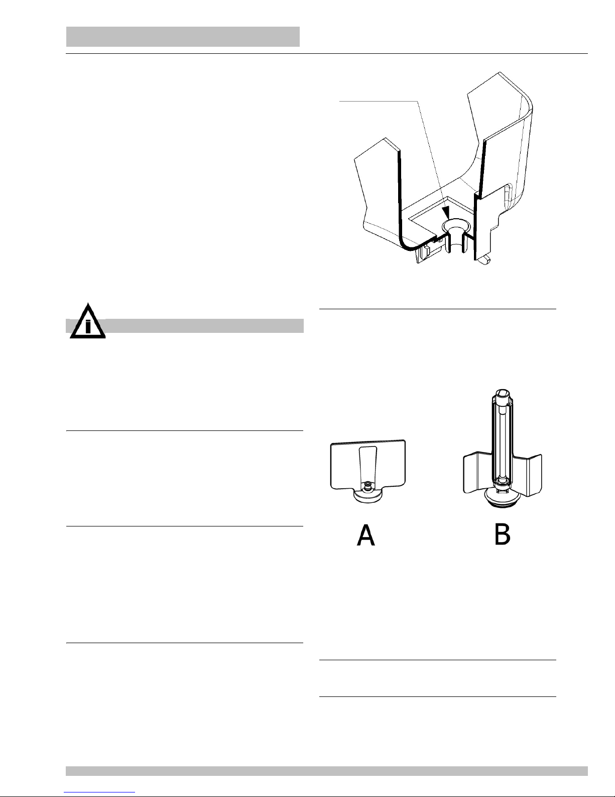
4. 2 STAINLESS STEEL GRAVITY FAUCET
This faucet is suitable for liquid prod uct without pulps or other
solid particles. In case of dripping, it is necessary to drain the
product out of the bowl, remove the stainless steel piston, clean
it with fresh water and check for wear of the rubber gasket. If
necessary, replace it with a new one. It is also necessary to
clean the piston housing in the bottom of the bowl and check for
the integrity of the rim around the piston hole (see figure 5).
figure 5
5 SLOW MIXING SYSTEM
The dispensers of Arctic Deluxe series are available also with
slow mixers. Two kind of slow mixers are available: one with
magnetic driving (A) and the other with mechanic driving (B).
The first one is suitable for delicate drinks like tea or coffee while
the other one is suitable also for thick drinks (see figure 6).
figure 6
In case of magnetic slow mixer improper rotation, the cause can
be a faulty drive motor, a magnetic mixer that can’t freely rotate
on its pivot or ice on the evaporator caused by very low level of
product into the bowl.
In case of direct slow mixer improper rotation the cause can be
a foulty motor or an excessive thickness of the drink.
6 REFRIGERANT CIRCUIT SERVICE
6. 1 CHECKING FOR REFRIGERANT LEAKS
The following procedure is the recommended approach to
systematically inspect the entire system for refrigerant leaks
NOTE: when using refrigerant detector, follow along the bottom
IMPORTANT
The impellers are designed to spin always submerged
and wet. It is very important to avoid to have them
spinning dry to prevent worn out. For this reason on
Arctic Deluxe always switch off pump of empty bowls
and on Arctic Compact remove the impeller of empty
bowls or fill them with water.
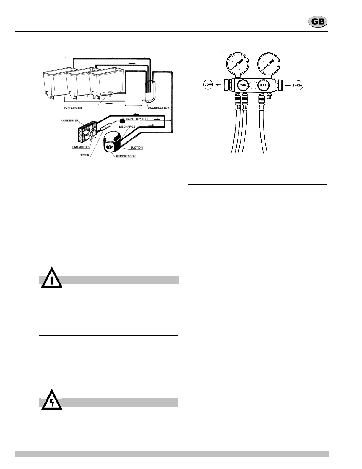
7
side of the copper tubing since the refrigerant gas is heavier
than air. Where copper tubing is protected by an insulating
jacket, check for leaks at both ends of each jacket section.
.
figure 7
Referring to the diagram (see figure 7), perform the following
steps:
1 Start inspection at the high pressure line of the compressor.
Check around the soldered connection.
2 Follow the copper tubing to the condenser and check
around the soldered connections at the top and bottom of the
condenser.
3 Check also along the copper curves on both sides of
condenser.
4 Follow the copper tubing to the evaporators, checking
around the soldered connections of dryer.
5 Remove mixer motors and check the inlet (capillary) and
outlet (suction) tubing.
6 Check the copper tubing all the way back to the
compressor.
7 Check around the low side connections of the compressor
suction and process tubes.
If a leak has been detected, seal it and make a new refrigerant
charge as per instructions in the following paragraphs.
6. 2 DISCHARGING
1 Remove the dispenser panels.
2 If not present install a charging valve on the compressor
process tube.
3 Remove the screw cap from the compressor process tube.
4 Connect the process tube to the LOW part of the gauge set.
5 Connect the VAC port of the gauge set to an adequate
approved gas recovery system.
6 Open the LOW and VAC valves and recover the refrigerant.
7 Once the recovery operation is completed, close the LOW
and VAC valves and disconnect the recovery system.(see
figure 8)
figure 8
6. 3 EVACUATING
Always install a brand new liquid line filter dryer before
evacuating.
1 Connect the REF port of the gauge set to the charging unit.
2 Connect the VAC port of the gauge set to the vacuum pump
and open the VAC valve.
3 Open the line valve of the charging unit and, for a while,
also the REF valve, so as to purge air from the REF hose.
4 Open the LOW valve of the gauge set and turn on the
vacuum pump for a minimum of half an hour.
5 While the pump is running, close the VAC valve once a
vacuum has been established.
6 Turn off the vacuum pump.
6. 4 CHARGING
The gauge set is usually w ith four ports and four valves (se e
figure 8). This is the easiest option to be found in the market
since it allows the charging through both low and high side of the
system. Our refrigeration systems are manufactured so as to be
chargeable through the compressor process tube only (low
side): thus, the HI port is never mentioned nor used in the
following procedure and therefore the HI valve must be kept
closed.
1 Determine how many ounces/grams should be filled by the
charging unit. This information can be found on the dispenser
data plate.
2 Remove bowls and mixers from the dispenser.
3 Plug in the dispenser and turn on the power switch.
4 Open the line valve of the charging unit.
5 Open the REF valve very slowly so as to allow the
refrigerant to be pulled into the system as a gas.
6 When the amount of refrigerant listed on the data plate ha s
been used, the system is charged. Close the REF valve and
the charging unit line valve and allow the compressor to run few
minutes.
7 Ensure that all evaporator plates are covered with frost.
8 Close the LOW valve, disconnect the LOW hose from the
compressor process tube and tighten the screw cap.
The following table reports the suction and discharge pressures
of the machines with the different refrigerants.
They must be verified under the following conditions:
Ambient temperature: 32 °C
Product temperature in the bowls: 5 °C
Evaporation temperature approx -5 °C
Condensation temperature approx 50°C.
IMPORTANT
To check for a leak in the low side of the system, it is
advisable to have the evaporators at least at ambient
temperature.
ATTENTION
The refrigerant gas could be highly acid and toxic.
8
ARCTIC COMPACT & DELUXE
6. 5 COMPRESSOR BURN-OUT
To determine if a burn-out has occurred, perform the following
steps:
1 Disconnect the unit from power source.
2 Remove wiring from the compressor terminals.
3 Using an ohmmeter, check for ground between the
terminals and the compressor housing. If a reading exists, the
compressor has shorted to ground.
In this case compressor must be replaced as per follow ing
steps:
4 Recover the refrigerant using an approved refrigeration
recovery system as per DISCHARGING instructions.
5 Remove the burned-out compressor.
6 Correct the system fault which caused the burn-out. Check
the condition of the capacitor(s) and compressor relay.
7 Install a new compressor and liquid line filter dryer.
8 Evacuate and charge the system as per EVACUATING and
CHARGING instructions.
7 ROUTINE MAINTENANCE
DAILY
Inspect the machine for signs of product leaks past seals and
gaskets. If proper assembly does not stop leaks around seal or
gaskets, check for improper lubrication, worn or damaged parts.
Replace parts as needed with original spare parts from the
supplier.
WEEKLY
Clean and sanitize the machine following the procedures
illustrated on the Operator's Manual of the unit. Check for worn
impellers, bowl gaskets, faucet pinch tubes or stainless steel
piston gaskets. Replace parts as needed with original spare
parts from the supplier.
MONTHLY
Clean all internal components, primarily the condenser, using
compressed air, vacuum or a soft brush.
To clean these internal parts, unplug the unit and remove the
panels. Condenser fins are very sharp. Use extreme caution
when cleaning.
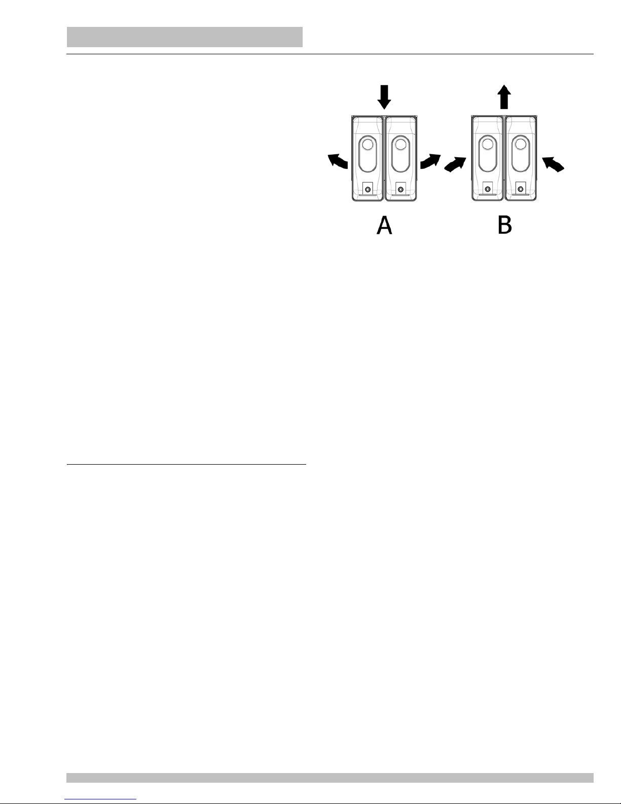
On Arctic Delux e dispensers the condenser is located on the
back of the unit and air flow is from back to sides (A). To clean
the condenser it is necessary to remove the back panel.
On Arctic Compact dispense rs the condenser is always
located on the back of the unit but air flow if from sid es to b ack
(B). To clean the condenser it is necessary to remove the faucet
side panel and to clean it from the inside of the unit (see figure
5).
figure 9
Refrigerant Suction (low)
pressure
Discharge (high)
pressure
R134a 1,43 bar 12,17 bar
R22 3,20 bar 18,39 bar
R404a 4,10 bar 21,93 bar

9
 Loading...