

UEi RACKtangle DNR-12-1G-02, HalfRACK DNR-6-1G, RACKtangle DNR-12-1G, RACKtangle DNR-12-1G-00, RACKtangle DNR-12-1G-01 User Manual
...Page 1

DNR-12-1G Series RACKtangle
and
DNR-6-1G Series HalfRACK
Data Acquisition Systems
—
User Manual
October 2018
PN Man-DNR-X-1G
© Copyright 1998-2018 United Electronic Industries, Inc. All rights reserved.
Page 2

Information furnished in this manual is believed to be accurate and reliable. However , no responsibility
is assumed for its use, or for any infringement of patents or other rights of third parties that may result
from its use.
All product names listed are trademarks or trade names of their respective companies.
See the UEI website for complete terms and conditions of sale:
http://www.ueidaq.com/cms/terms-and-conditions/
Contacting United Electronic Industries
Mailing Address:
27 Renmar Avenue
Walpole, MA 02081
U.S.A.
For a list of our distributors and partners in the US and around the world, please contact a memb er of our
support team:
Support:
Telephone: (508) 921-4600
Fax: (508) 668-2350
Also see the FAQs and online “Live Help” feature on our web site.
Internet Support:
Support: support@ueidaq.com
Website: www.ueidaq.com
FTP site: ftp://ftp.ueidaq.com
Product Disclaimer:
WARNING!
DO NOT USE PRODUCTS SOLD BY UNITED ELECTRONIC INDUSTRIES, INC. AS CRITICAL
COMPONENTS IN LIFE SUPPORT DEVICES OR SYSTEMS.
Products sold by United Electronic Industries, Inc. are not authorized for use as critical components in
life support devices or systems. A critical component is any component of a life support device or
system whose failure to perform can be reasonably expected to cause the failure of the life support
device or system, or to affect its safety or effectiveness. Any attempt to purchase any United Electronic
Industries, Inc. product for that purpose is null and void and United Electronic Industries Inc. accepts
no liability whatsoever in contract, tort, or otherwise whether or not resulting from our or our
employees' negligence or failure to detect an improper purchase.
Specifications in this document are subject to change without notice. Check with UEI for
current status.
Page 3

DNR-X-1G Series RACKtangle and HalfRACK Systems i
October 2018 www.ueidaq.com
508.921.4600
© Copyright 2018
United Electronic Industries, Inc.
Table of Contents
Table of Contents
Chapter 1 Introduction . . . . . . . . . . . . . . . . . . . . . . . . . . . . . . . . . . . . . . . . . . . . . . . . . . . . 1
1.1 Organization of This Manual. . . . . . . . . . . . . . . . . . . . . . . . . . . . . . . . . . . . . . . . . . . . 1
1.2 Product Versions Described in This Manual. . . . . . . . . . . . . . . . . . . . . . . . . . . . . . . . 3
Chapter 2 The DNR-12-1G Series RACKtangle System . . . . . . . . . . . . . . . . . . . . . . . . . . 4
2.1 PowerDNR DNR-12-1G System Overview. . . . . . . . . . . . . . . . . . . . . . . . . . . . . . . . . 4
2.2 DNR-12-1G Specifications . . . . . . . . . . . . . . . . . . . . . . . . . . . . . . . . . . . . . . . . . . . . . 6
2.3 DNR-12-1G Key Features. . . . . . . . . . . . . . . . . . . . . . . . . . . . . . . . . . . . . . . . . . . . . . 7
2.4 DNR-12-1G RACKtangle Enclosure . . . . . . . . . . . . . . . . . . . . . . . . . . . . . . . . . . . . . . 8
2.4.1 DNR-12-1G Enclosure. . . . . . . . . . . . . . . . . . . . . . . . . . . . . . . . . . . . . . . . . . . 8
2.4.2 DNR-12-1G Enclosure Common Components . . . . . . . . . . . . . . . . . . . . . . . . 8
2.4.3 DNR-12-1G Cooling Air Flow. . . . . . . . . . . . . . . . . . . . . . . . . . . . . . . . . . . . . 13
2.5 DNR-12 Power, NIC/CPU, and I/O Boards LEDs & Controls . . . . . . . . . . . . . . . . . . 14
2.6 DNR-POWER-DC Module . . . . . . . . . . . . . . . . . . . . . . . . . . . . . . . . . . . . . . . . . . . . 17
2.7 DNR-CPU/NIC Module . . . . . . . . . . . . . . . . . . . . . . . . . . . . . . . . . . . . . . . . . . . . . . . 21
2.7.1 Device Architecture of DNR Core Module . . . . . . . . . . . . . . . . . . . . . . . . . . . 22
2.8 DNR-Buffer Module. . . . . . . . . . . . . . . . . . . . . . . . . . . . . . . . . . . . . . . . . . . . . . . . . . 24
2.9 DNR I/O Boards . . . . . . . . . . . . . . . . . . . . . . . . . . . . . . . . . . . . . . . . . . . . . . . . . . . . 24
2.10 DNR-12-1G DC Power Thresholds. . . . . . . . . . . . . . . . . . . . . . . . . . . . . . . . . . . . . . 24
Chapter 3 The DNR-6-1G Series HalfRACK System . . . . . . . . . . . . . . . . . . . . . . . . . . . . 25
3.1 PowerDNR DNR-6-1G System Overview. . . . . . . . . . . . . . . . . . . . . . . . . . . . . . . . . 25
3.2 DNR-6-1G Specifications . . . . . . . . . . . . . . . . . . . . . . . . . . . . . . . . . . . . . . . . . . . . . 27
3.3 DNR-6-1G Key Features. . . . . . . . . . . . . . . . . . . . . . . . . . . . . . . . . . . . . . . . . . . . . . 28
3.4 DNR-6-1G HalfRACK Enclosure. . . . . . . . . . . . . . . . . . . . . . . . . . . . . . . . . . . . . . . . 29
3.4.1 DNR-6-1G Enclosure. . . . . . . . . . . . . . . . . . . . . . . . . . . . . . . . . . . . . . . . . . . 29
3.4.2 DNR-6-1G Enclosure Common Components . . . . . . . . . . . . . . . . . . . . . . . . 30
3.4.3 DNR-6-1G Cooling Air Flow. . . . . . . . . . . . . . . . . . . . . . . . . . . . . . . . . . . . . . 32
3.5 DNR-6 Power, NIC/CPU, and I/O Boards LEDs & Controls . . . . . . . . . . . . . . . . . . . 33
3.6 DNR-6-1G DNR-POWER-DC Module . . . . . . . . . . . . . . . . . . . . . . . . . . . . . . . . . . . 34
3.7 DNR-6-1G DNR-CPU/NIC Module . . . . . . . . . . . . . . . . . . . . . . . . . . . . . . . . . . . . . . 34
3.8 DNR-6-1G DNR-IO-Modules . . . . . . . . . . . . . . . . . . . . . . . . . . . . . . . . . . . . . . . . . . 34
3.9 DNR-6-1G DC Power Thresholds. . . . . . . . . . . . . . . . . . . . . . . . . . . . . . . . . . . . . . . 35
Chapter 4 Installation and Configuration . . . . . . . . . . . . . . . . . . . . . . . . . . . . . . . . . . . . 36
4.1 Initial Installation Guide. . . . . . . . . . . . . . . . . . . . . . . . . . . . . . . . . . . . . . . . . . . . . . . 36
4.1.1 Inspect Package . . . . . . . . . . . . . . . . . . . . . . . . . . . . . . . . . . . . . . . . . . . . . . 37
4.1.2 Install Software . . . . . . . . . . . . . . . . . . . . . . . . . . . . . . . . . . . . . . . . . . . . . . . 37
4.2 Initial Boot-up . . . . . . . . . . . . . . . . . . . . . . . . . . . . . . . . . . . . . . . . . . . . . . . . . . . . . . 39
4.3 IP Address Overview & Update Procedures. . . . . . . . . . . . . . . . . . . . . . . . . . . . . . . 41
Page 4

DNR-X-1G Series RACKtangle and HalfRACK Systems ii
October 2018 www.ueidaq.com
508.921.4600
© Copyright 2018
United Electronic Industries, Inc.
Table of Contents
4.3.1 When Should You Change the IP Address? . . . . . . . . . . . . . . . . . . . . . . . . . 41
4.3.2 How to Change the Primary IP Address (NIC1). . . . . . . . . . . . . . . . . . . . . . . 42
4.3.3 How to Change the Secondary (Diagnostic) IP Address (NIC2). . . . . . . . . . 43
4.4 Network Configuration . . . . . . . . . . . . . . . . . . . . . . . . . . . . . . . . . . . . . . . . . . . . . . . 44
4.4.1 Example of Configuring Network Settings . . . . . . . . . . . . . . . . . . . . . . . . . . . 45
4.5 Troubleshooting . . . . . . . . . . . . . . . . . . . . . . . . . . . . . . . . . . . . . . . . . . . . . . . . . . . . 49
4.6 Updating Firmware . . . . . . . . . . . . . . . . . . . . . . . . . . . . . . . . . . . . . . . . . . . . . . . . . . 50
4.6.1 Determining Currently Installed Firmware Version . . . . . . . . . . . . . . . . . . . . 51
4.6.2 Updating Firmware via PowerDNA Explorer . . . . . . . . . . . . . . . . . . . . . . . . . 52
4.6.3 Updating Firmware via Serial Interface . . . . . . . . . . . . . . . . . . . . . . . . . . . . . 54
4.7 Mounting and Field Connections . . . . . . . . . . . . . . . . . . . . . . . . . . . . . . . . . . . . . . . 56
4.7.1 Physical Dimensions . . . . . . . . . . . . . . . . . . . . . . . . . . . . . . . . . . . . . . . . . . . 56
4.7.2 Pinout Diagrams . . . . . . . . . . . . . . . . . . . . . . . . . . . . . . . . . . . . . . . . . . . . . . 58
4.7.3 Network Wiring. . . . . . . . . . . . . . . . . . . . . . . . . . . . . . . . . . . . . . . . . . . . . . . . 58
4.8 Wiring I/O Boards . . . . . . . . . . . . . . . . . . . . . . . . . . . . . . . . . . . . . . . . . . . . . . . . . . . 59
4.9 Repairing (and Upgrading) a DNR System. . . . . . . . . . . . . . . . . . . . . . . . . . . . . . . . 59
4.10 Configuring a NIC Port for Diagnostic Mode. . . . . . . . . . . . . . . . . . . . . . . . . . . . . . . 59
4.11 Disabling Writes to Flash/EEPROM (NVRAM) . . . . . . . . . . . . . . . . . . . . . . . . . . . . . 66
4.11.1 Disabling NVRAM Writes. . . . . . . . . . . . . . . . . . . . . . . . . . . . . . . . . . . . . . . . 66
4.11.2 Re-enabling NVRAM Writes . . . . . . . . . . . . . . . . . . . . . . . . . . . . . . . . . . . . . 68
Chapter 5 PowerDNA Explorer . . . . . . . . . . . . . . . . . . . . . . . . . . . . . . . . . . . . . . . . . . . . . 69
5.1 Getting Started with PowerDNA Explorer . . . . . . . . . . . . . . . . . . . . . . . . . . . . . . . . . 69
5.1.1 Connecting PowerDNA Explorer to Your System . . . . . . . . . . . . . . . . . . . . . 70
5.2 Overview of the Main Window . . . . . . . . . . . . . . . . . . . . . . . . . . . . . . . . . . . . . . . . . 72
5.2.1 Menu Bar . . . . . . . . . . . . . . . . . . . . . . . . . . . . . . . . . . . . . . . . . . . . . . . . . . . . 72
5.2.2 Toolbar. . . . . . . . . . . . . . . . . . . . . . . . . . . . . . . . . . . . . . . . . . . . . . . . . . . . . . 78
5.2.3 Device Tree . . . . . . . . . . . . . . . . . . . . . . . . . . . . . . . . . . . . . . . . . . . . . . . . . . 78
5.2.4 Settings Panel . . . . . . . . . . . . . . . . . . . . . . . . . . . . . . . . . . . . . . . . . . . . . . . . 80
5.3 Exploring I/O Boards with PowerDNA Explorer . . . . . . . . . . . . . . . . . . . . . . . . . . . . 83
5.3.1 Digital Input/Output Board Settings . . . . . . . . . . . . . . . . . . . . . . . . . . . . . . . . 83
5.3.2 Analog Output Board Settings . . . . . . . . . . . . . . . . . . . . . . . . . . . . . . . . . . . . 86
5.3.3 Analog Input Board Settings . . . . . . . . . . . . . . . . . . . . . . . . . . . . . . . . . . . . . 87
5.3.4 Counter/Timer Board Settings . . . . . . . . . . . . . . . . . . . . . . . . . . . . . . . . . . . . 88
Chapter 6 Programming CPU Board-specific Functions . . . . . . . . . . . . . . . . . . . . . . . . 91
6.1 Overview. . . . . . . . . . . . . . . . . . . . . . . . . . . . . . . . . . . . . . . . . . . . . . . . . . . . . . . . . . 91
6.2 Memory Map Overview. . . . . . . . . . . . . . . . . . . . . . . . . . . . . . . . . . . . . . . . . . . . . . . 91
6.3 Startup Sequence. . . . . . . . . . . . . . . . . . . . . . . . . . . . . . . . . . . . . . . . . . . . . . . . . . . 93
6.4 Setting and Reading CPU Core Parameters via Serial Port. . . . . . . . . . . . . . . . . . . 93
6.4.1 Help Command . . . . . . . . . . . . . . . . . . . . . . . . . . . . . . . . . . . . . . . . . . . . . . . 94
6.4.2 Show System Parameters Command . . . . . . . . . . . . . . . . . . . . . . . . . . . . . . 95
6.4.3 Set and Store Commands . . . . . . . . . . . . . . . . . . . . . . . . . . . . . . . . . . . . . . . 96
6.4.4 Reset DNR-X-1G Command . . . . . . . . . . . . . . . . . . . . . . . . . . . . . . . . . . . . . 99
6.4.5 Password Command . . . . . . . . . . . . . . . . . . . . . . . . . . . . . . . . . . . . . . . . . . 100
6.4.6 Display Table of Installed Boards & Logic Version Command. . . . . . . . . . . 100
6.4.7 Display Power Diagnostics Command. . . . . . . . . . . . . . . . . . . . . . . . . . . . . 102
Page 5

DNR-X-1G Series RACKtangle and HalfRACK Systems iii
October 2018 www.ueidaq.com
508.921.4600
© Copyright 2018
United Electronic Industries, Inc.
Table of Contents
6.4.8 Memory Test/Memory Clear Command. . . . . . . . . . . . . . . . . . . . . . . . . . . . 103
6.4.9 Monitor CPU and Pbuf Usage Command . . . . . . . . . . . . . . . . . . . . . . . . . . 103
6.4.10 Clock and Watchdog Access Command . . . . . . . . . . . . . . . . . . . . . . . . . . . 104
Appendix A . . . . . . . . . . . . . . . . . . . . . . . . . . . . . . . . . . . . . . . . . . . . . . . . . . . . . . . . . . . . . 105
Network Interface Card Configuration
Appendix B . . . . . . . . . . . . . . . . . . . . . . . . . . . . . . . . . . . . . . . . . . . . . . . . . . . . . . . . . . . . . 109
Field Replacement of Fuses on DNA and DNR Boards
Index . . . . . . . . . . . . . . . . . . . . . . . . . . . . . . . . . . . . . . . . . . . . . . . . . . . . . . . . . . . . . . . . . 111
Page 6

DNR-X-1G Series RACKtangle and HalfRACK Systems iv
October 2018 www.ueidaq.com
508.921.4600
© Copyright 2018
United Electronic Industries, Inc.
List of Figures
List of Figures
Chapter 1 Introduction . . . . . . . . . . . . . . . . . . . . . . . . . . . . . . . . . . . . . . . . . . . . . . . . . . . . . 1
Chapter 2 The DNR-12-1G Series RACKtangle System . . . . . . . . . . . . . . . . . . . . . . . . . . 4
2-1 Typical DNR-12-1G RACKtangle System......................................................................4
2-2 DNR-12-1G Technical Specifications....... .....................................................................6
2-3 DNR-12-1G PowerDNR Product Features....................................................................7
2-4 Typical PowerDNR DNR-12 Enclosure (Exploded View)..............................................8
2-5 Typical PowerDNR DNR-12 Board Placement..............................................................9
2-6 Optional DNR-IO-Filler Panel for Empty Slots.............................................................11
2-7 DNR-BRACKET Reversible Mounting Bracket............................................................11
2-8 DNR Board Ejection/Insertion Lever Operation...........................................................12
2-9 DNR-12 Air Flow..........................................................................................................13
2-10 DNR-12-1G System Front Panel Arrangement............ ... ... ... ... .... ... ... ... .... ... ... ............14
2-11 DC Power Module LEDs..............................................................................................15
2-12 DNR-CPU-1000/-XX Module LEDs.............................................................................15
2-13 Typical I/O Module LEDs.............................................................................................16
2-14 DNR-POWER-DC Module...........................................................................................18
2-15 Functional Block Diagram of DNR-POWER-DC Module.............................................19
2-16 Functional Block Diagram of DNR-12 Enclosure.........................................................20
2-17 DNR-X-1G Series Core Module (CPU/NIC) ................................................................21
2-18 FreeScale PowerPC CPU/NIC Controller Architecture................................................22
Chapter 3 The DNR-6-1G Series HalfRACK System . . . . . . . . . . . . . . . . . . . . . . . . . . . . 25
3-1 Typical DNR-6-1G HalfRACK System.........................................................................25
3-2 DNR-6-1G Technical Specifications............................................................................27
3-3 DNR-6-1G HalfRACK Product Features......................................................................28
3-4 Typical HalfRACK DNR-6 Enclosure (Exploded View)....... ... ... ...................................29
3-5 Typical PowerDNR DNR-6 Board Placement..............................................................30
3-6 DNR-6 Air Flow............................................................................................................32
3-7 DNR-6-1G System Front Panel Arrangement.............................................................33
Chapter 4 Installation and Configuration . . . . . . . . . . . . . . . . . . . . . . . . . . . . . . . . . . . . . 36
4-1 Typical MTTTY Screen after DNR-X-1G Boot-up........................................................40
4-2 System Configuration Using show Command.............................................................41
4-3 Using PowerDNA Explorer to Change IP Address......................................................42
4-4 Single DNR-X-1G Direct-Connected to Host without LAN Switch...............................44
4-5 Single Network for Operation and Diagnostics Using DNR Racks and LAN Switch ...44
4-6 Separate Networks for Operation and Diagnostics: Two Racks & Two Switches.......45
4-7 Typical Configuration for a Single DNR-X-1G with a LAN Switch ... ... ... ......................48
4-8 Displaying the Version of Your Firmware....................................................................51
4-9 Update Firmware Menu Item.......................................................................................52
4-10 Password Dialog Box ..................................................................................................53
4-11 Firmware Update Progress Dialog Box.......................................................................53
4-12 Firmware Update via Serial Port..................................................................................55
4-13 Physical Dimensions of DNR-12 Enclosure.................................................................56
4-14 Physical Dimensions of DNR-6 Enclosure...................................................................57
4-15 DNR-X-1G Pinout Diagrams........................................................................................58
4-16 System Configuration with LAN Switch.......................................................................58
4-17 DNR-X-1G NIC/CPU Core Module and Carrier...........................................................66
4-18 NVRAM Protection Jumper .........................................................................................67
Page 7

DNR-X-1G Series RACKtangle and HalfRACK Systems v
October 2018 www.ueidaq.com
508.921.4600
© Copyright 2018
United Electronic Industries, Inc.
List of Figures
Chapter 5 PowerDNA Explorer . . . . . . . . . . . . . . . . . . . . . . . . . . . . . . . . . . . . . . . . . . . . . 69
5-1 PowerDNA Explorer ....................................................................................................69
5-2 Address Ranges to be Scanned..................................................................................70
5-3 Typical Screen for Analog Input Board........................................................................71
5-4 PowerDNA Explorer Main Window..............................................................................72
5-5 PowerDNA Explorer Timeout Preferences..................................................................72
5-6 Address Ranges Dialog Box........................................................................................73
5-7 Edit Address Ranges Dialog Box ................................................................................73
5-8 After a Network >>Scan Network................................................................................74
5-9 Password Dialog Box for “Store Config” and “Store All Configs”.................................75
5-10 Password Dialog Box for “Update Firmware . . .”........................................................75
5-11 Example of a Hardware Report...................................................................................76
5-12 Example of a Wiring Diagram Display.........................................................................77
5-13 PowerDNA Explorer Toolbar Buttons (Config Level)...................................................78
5-14 PowerDNA Explorer Toolbar Buttons (Board Level)....................................................78
5-15 Example of the Device Tree........................................................................................79
5-16 Example of IOM Settings Panel for HalfRACK DNR-6-1G..........................................80
5-17 Example of I/O Device Settings ..................................................................................81
5-18 Screen from Network >> Start Reading Input Data.....................................................82
5-19 Example DIO-403 Inputs.............................................................................................83
5-20 Example DIO-403 Outputs ..........................................................................................84
5-21 Example of DIO-403 Configuration..............................................................................85
5-22 Example AO-308 Board...............................................................................................86
5-23 Example AI-207 Board ................................................................................................87
5-24 Example CT-601 Module.............................................................................................88
5-25 Example Quadrature Controls.....................................................................................88
5-26 Example Bin Counter Controls....................................................................................89
5-27 Example Pulse Width Modulation (PWM) Controls.....................................................89
5-28 Example Pulse Period Controls...................................................................................89
5-29 Example Frequency Controls......................................................................................89
5-30 Example of Started Counter........................................................................................90
Chapter 6 Programming CPU Board-specific Functions . . . . . . . . . . . . . . . . . . . . . . . . 91
6-1 TCP/IP Properties........................................................................................................98
B-1 Location of Fuse for Base Boards Equipped with a Fuse..........................................109
B-2 Location of Fuses for DNR-POWER-DC Board ................. ... ... .... ... ... ... .... ................110
B-3 Location of Fuses for DNR-POWER-1GB Board.......................................................110
Page 8

DNR-X-1G Series RACKtangle and HalfRACK Systems vi
October 2018 www.ueidaq.com
508.921.4600
© Copyright 2018
United Electronic Industries, Inc.
List of Figures
List of Tables
Chapter 1 Introduction . . . . . . . . . . . . . . . . . . . . . . . . . . . . . . . . . . . . . . . . . . . . . . . . . . . . . 1
1-1 Summary of DNR-X-1G/DNR-X-1G-XX Product Versions...........................................3
Chapter 2 The DNR-12-1G Series RACKtangle System . . . . . . . . . . . . . . . . . . . . . . . . . . 4
2-1 Components in PowerDNR DNR-12 Enclosure............................................................9
2-2 Components in PowerDNR Core Module (DNR-CPU-1000 Series)...........................22
Chapter 3 The DNR-6-1G Series HalfRACK System . . . . . . . . . . . . . . . . . . . . . . . . . . . . 25
3-1 Components in PowerDNR DNR-6 Enclosure............................................................30
Chapter 4 Installation and Configuration . . . . . . . . . . . . . . . . . . . . . . . . . . . . . . . . . . . . . 36
4-1 Port States..................................................................................................................60
4-2 List of Functions and Associated Boards ...................................................................64
Chapter 5 PowerDNA Explorer . . . . . . . . . . . . . . . . . . . . . . . . . . . . . . . . . . . . . . . . . . . . . 69
5-1 Fields and Descriptions for IOM Settings Panel................................... .... ... ...............80
5-2 Fields and Descriptions for I/O Device Settings Panel................................ ... ... ... .... ..81
Chapter 6 Programming CPU Board-specific Functions . . . . . . . . . . . . . . . . . . . . . . . . 91
6-1 Memory Map for DNR-X-1G CPU (DNR-CPU-1000) .................................................91
6-2 Memory Map for DNR-X-1G-02 CPU (DNR-CPU-1000-02).......................................92
6-3 Memory Map for DNR-X-1G-03 CPU (DNR-CPU-1000-03).......................................92
6-4 Set Parameters...........................................................................................................97
B-1 DNA/DNR Replacement Fuses .. ... .... ... ... ... .... ... ... ... .... ... ... ... ... .... ... ... ... ....................109
Page 9

October 2018 www.ueidaq.com
508.921.4600
© Copyright 2018
United Electronic Industries, Inc.
Chapter 1 Introduction
This document describes the features, performance specifications, and
operating functions of the DNR-12-1G Series RACKtangle
Series HalfRACK
RACKtangle and HalfRACK versions are identical except for the size of the
enclosure and the number of IO boards that can be installed. Both are designed
for use with a Gigabit Ethernet 1000 Base-T communication network.
This chapter provides the following information about the DNR-X-1G systems:
• Organization of This Manual (Section 1.1)
• Product Versions Described in This Manual (Section 1.2)
data acquisition systems.
DNR-X-1G Series RACKtangle and HalfRACK Systems
Chapter 1 1
Introduction
and the DNR-6-1 G
1.1 Organization of This Manual
This DNR-X-1G User Manual is organized as follows:
• Chapter 1 – Introduction
This chapter describes the organi zation of the document and the
conventions used throughout the manual.
• Chapter 2 – DNR-12-1G Series RACKtangle
This chapter provides an overview of a DNR-12-1G system, features,
accessories, and a list of all items you need for initial operation.
• Chapter 3 – DNR-6-1G Series HalfRACK
This chapter provides an overview of a DNR-6-1G system, features, and
accessories. It is essentially the same as the DNR-12-1G system except
for enclosure size and number and arrangement of I/O boards.
• Chapter 4 – Installation and Configuration
This chapter summarizes the recommended procedures for installing,
configuring, starting up, and troubleshooting a DNR-X-1G system.
• Chapter 5 – PowerDNA Explorer
This chapter provides a general description of the menus and screens of
UEI’s GUI-based communication application, PowerDNA Explorer,
when used with a DNR-X-1G system.
• Chapter 6 – Programming CPU Board-specific Functions
This chapter describes tools and facilities used for programming boardspecific functions.
System
System
• Appendix A – Configuring Additional Ethernet Cards
This appendix describes procedures for installing and configuring
Ethernet cards for use with Windows operating systems.
• Appendix B – Field Replacement of Fuses
This appendix describes procedures for replacing fuses in the field.
• Index
This is an alphabetical listing of topics covered in the manual, identified
by page number.
Page 10

DNR-X-1G Series RACKtangle and HalfRACK Systems
October 2018 www.ueidaq.com
508.921.4600
© Copyright 2018
United Electronic Industries, Inc.
Chapter 1 2
Introduction
Manual Conventions
To help you get the most out of this manual and our products, please note that
we use the following conventions:
Tips are designed to highlight quick ways to get the job done, or reveal
good ideas you might not discover on your own.
NOTE: Notes alert you to important information.
CAUTION! advises you of precautions to take to avoid injury, data loss, and
damage to your boards or a system crash.
T ext formatted in bold typeface g enerally represents text that shou ld be entered
verbatim. For instance, it can represent a filenames, as in the following example:
“You can instruct users how to run setup using setup.exe executable.”
Bold typeface will also represent button names, as in “Click Scan Network.”
Text formatted in fixed typeface generally represents commands,
source code, or other text that should be entered verbatim into the source code,
initialization, or other file or at a command prompt.
Before you begin:
Before plugging any I/O connector into the chassis or board(s), be sure to
remove power from all field wiring. Failure to do so may cause severe
damage to the equipment.
No HOT SWAP
Always turn POWER OFF before performing maintenance on a UEI system.
Failure to observe this warning may result in damage to the equipment and
possible injury to personnel.
Usage of Terms
Throughout this manual, the term “Cube” refers to either a PowerDNA Cube
product or to a PowerDNA RACKtangle
applicable.
Additionally throughout this manual, the following conventions apply:
• “DNR-X-1G” refers to both DNR-12-1G and DNR-6-1G types of
systems. The DNR-12-1G can accept up to 12 I/O boards and the
DNR-6-1G can accept up to 6 I/O boards. The two models are identical
in all other respects.
rack mounted system, whichever is
• Unless otherwise noted, “DNR-X-1G” applies to all versions of the
RACKtangle and HalfRACK systems: DNR-X-1G (-00/-01),
DNR-X-1G-02, and DNR-X-1G-03. Differences between product
versions are noted on the following page.
Note that the -02 product version is a fully compatible upgrade of the
-00/-01 version.
Page 11

DNR-X-1G Series RACKtangle and HalfRACK Systems
October 2018 www.ueidaq.com
508.921.4600
© Copyright 2018
United Electronic Industries, Inc.
Chapter 1 3
Introduction
1.2 Product Versions Described in This Manual
This user manual provides documentation for the DNR-X-1G series data
acquisition systems: DNR-X-1G, DNR-X-1G-02, and DNR-X-1G-03 product
versions.
Each product version is available in a DNR-12-1G RACKtangle chassis or a
DNR-6-1G HalfRACK chassis.
T able 1-1 below provides a summary of features for each prod uct version. Refer
to the following chapters in this manual for detailed descriptions.
NOTE: Unless otherwise noted, DNR-X-1G refers collectively to the
DNR-X-1G(-00/-01), DNR-X-1G-02, and DNR-X-1G-03 series of
products.
Table 1-1 Summary of DNR-X-1G/DNR-X -1G-XX Product Versions
Item Summary of Features
DNR-X-1G
(DNR-X-1G-00 /
DNR-X-1G-01)
• 10/100/1000Base-T Ethernet interface
• Freescale MPC8347 CPU
• 1PPS synchronization support
• 128 MB RAM
• 32 MB flash memory
2
2
1
DNR-X-1G-02 • 10/100/1000Base-T Ethernet interface
• Freescale MPC8347 CPU
• 1PPS/IEEE-1588 synchronization support
• Optional solid-state hard drives
3
1
• 256 MB RAM2
• 32 MB flash memory
2
DNR-X-1G-03 • 10/100/1000Base-T Ethernet interface
• Freescale MPC8347E CPU, (encryption-ready / IPSec support
pending)
• 1PPS/IEEE-1588 synchronization support
• Optional solid-state hard drives
• 256 MB RAM
• 128 MB flash memory
2
2
3
1
1.1PPS and IEEE-1588 synchronization support is described in the PowerDNx 1PPS Sync Interface Manual.
2.RAM and flash memory are not user-accessible for PowerDNA applications (hosted deployment). Portions
of RAM and flash are available for UEIPAC-based systems (stand-alone deployment). See UEIPAC documentation for more information.
3.On UEIPAC-based systems (stand-alone deployment), solid state d rives are used for data and/or root file
system storage.See UEIPAC documentation for more information.
Page 12

DNR-X-1G Series RACKtangle and HalfRACK Systems
October 2018 www.ueidaq.com
508.921.4600
© Copyright 2018
United Electronic Industries, Inc.
The DNR-12-1G Series RACKtangle System
Chapter 2 4
Chapter 2 The DNR-12-1G Series RACKtangle System
This chapter provides the following information about the DNR-12-1G Series
RACKtangle
• PowerDNR DNR-12-1G System Overview (Section 2.1)
• DNR-12-1G Specifications (Section 2.2)
• DNR-12-1G Key Features (Section 2.3)
• DNR-12-1G RACKtangle Enclosure (Section 2.4)
• DNR-12 Power, NIC/CPU, and I/O Boards LEDs & Controls
• DNR-POWER-DC Module (Section 2.6)
• DNR-CPU/NIC Module (Section 2.7)
• DNR-Buffer Module (Section 2.8)
• DNR I/O Boards (Section 2.9)
• DNR-12-1G DC Power Thresholds (Section 2.10)
NOTE: For a list of product versions available for the DNR-12-1G Series
system:
(Section 2.5)
RACKtangle systems, refer to Section 1.2 on page 3.
2.1 PowerDNR DNR-12-1G System Overview
UEI PowerDNR DNR-12-1G RACKtangle systems are rack-mounted versions
of the PowerDNA Cube Ethernet-based data acquisition systems.
The DNR-12-1G houses a PowerDNA data acquisition system in a rack
enclosure with cabling, installation hardware, LEDs, and a power switc h
accessible from the front of the rack chassis. Multiple DNR-12-1G systems may
be mounted in a single rack. All standard DNA- Cube I/O boards are also
available in DNR- RACK versions for use in DNR-12-1G systems.
Figure 2-1. Typical DNR-12-1G RACKtangle System
Page 13

DNR-X-1G Series RACKtangle and HalfRACK Systems
October 2018 www.ueidaq.com
508.921.4600
© Copyright 2018
United Electronic Industries, Inc.
Chapter 2 5
The DNR-12-1G Series RACKtangle System
A standard DNR-12-1G rack system consists of the following:
• One or more DNR-12 rack mounted enclosure(s)
• DNR-POWER-DC Power Module (one for each enclosure)
• DNR-CPU-1000 or DNR-CPU-1000-XX Module
(Freescale MPC8347 or MPC8347E CPU and 1-GB Ethernet
1000 Base-T Network Interface Module — one for each enclosure)
• DNR-BUFFER Board Module (one for each enclosure)
• Optional DNR-IO-FILLER panels (one for each unused I/O slot)
Note: These slot covers are optional and not included in the price of the
rack
• DNA-PSU-180 180-Watt, 120/230 VAC to +24 VDC External Power
Supply (one for each enclosure) with cable and Molex connector for
plug-in to the DNR-POWER-DC Module front panel
T o configure a complete data acquisition system, insert up to 12 DNR I/O boards
into each PowerDNR rack enclosure. I/O boards may be specified in any
combination of UEI’s I/O boards.
All standard PowerDNA accessories are also available for use in a PowerDNR
rack-mount system.
NOTE: For detailed descriptions of all I/O boards and accessories available for
DNR-X-1G systems, refer to www.ueidaq.com.
UEI stand-alone systems (UEIPAC, UEISIM, UEIModbus, and UEIOPCUA
deployments) are also available for use with DNR-12-1G RACK systems:
• UEIPAC 1200R - Programmable Automation Controller
• UEISIM 1200R - Simulink / Simulink Coder Target
• UEIModbus 1200R - Modbus TCP-based Controller
• UEIOPCUA 1200R - OPC-UA Server, accessed by any OPC-UA client
Page 14

DNR-X-1G Series RACKtangle and HalfRACK Systems
October 2018 www.ueidaq.com
508.921.4600
© Copyright 2018
United Electronic Industries, Inc.
Standard Interfaces
To Host Computer Two independent 1000Base-T Gigabit Ethernet
ports (100/10Base-T compatible)
Distance from host 100 meters, max
Other Interfaces One USB 2.0 controller port, One USB 2.0 slave
port.
Cong/General RS-232, 9-pin “D”
Sync Custom cable to sync multiple racks
I/O Slots Available
DNR-12-1G 12 slots
Data transfer and communications rates
Ethernet data
transfer rate
20 megabytes per second
Analog data
transfer rate
up to 6 megasample per sec (16-bit samples)
DMAP I/O mode update 1000 I/O channels
(analog and/or digital)
in less than 1 millisecond, guaranteed
Processor
CPU Freescale 8347, 400 MHz, 32-bit
Memory 128 MB (not including on-board Flash)
Status LEDs Power supplies within spec, One second system
heart-beat, Attention, Read/Write, Power, Communications Active
Environmental
Temp (operating) Tested to -40 °C to 70 °C
Temp (storage) -40 °C to 85 °C
Humidity 0 to 95%, non-condensing
Vibration
(IEC 60068-2-64) 10–500 Hz, 3 g (rms), Broad-band random
(IEC 60068-2-6) 10–500 Hz, 3 g, Sinusoidal
Shock
(IEC 60068-2-27)
50 g, 3 ms half sine, 18 shocks at 6 orientations;
50 g, 11 ms half sine, 18 shocks at 6 orientations
MTBF 130,000 hours
Physical Dimensions
DNR-12 series 5.25” x 6.2” x 17.5” (3U in a 19” rack)
Power Requirements
Voltage 9 - 36 VDC (AC adaptor included)
Fuse Internal 10 A
Power Dissipation 13 W at 24 VDC (not including I/O boards)
Power Monitoring
I/O board power All internal power supplies monitored to ±1% ac-
curacy. All PS voltages may be read by host. LED
annunciators indicate out of range
Input current Monitored by host, LED indicates overcurrent
Chapter 2 6
The DNR-12-1G Series RACKtangle System
2.2 DNR-12-1G
Specifi-
Figure 2-2 lists the technical specifications of the DNR-12-1G PowerDNR
system.
cations
Figure 2-2. DNR-12-1G Technical Specifications
Page 15

DNR-X-1G Series RACKtangle and HalfRACK Systems
October 2018 www.ueidaq.com
508.921.4600
© Copyright 2018
United Electronic Industries, Inc.
Easy to Configure and Deploy
Over 30 different I/O boards available
Over 5 quadrillion possible configurations
Gigabit Ethernet based (100/10Base-T compatible)
Bracket kit for mounting to wall or in 19” racks
Industrial quality rubber feet for solid table-top mounting
Passive backplane ensures extremely low MTTR
Standard “Off-the-shelf” products and delivery
True Real-time Performance
1 msec updates guaranteed with 1000 I/O
Up to 6 million samples per second
Use QNX, RTX, 7Y8PSLT
Flexible Connectivity
1000Base-T with Cat-5 cable
Supports WIFI / GSM / Cell networks
Built-in USB 2.0 slave and controller ports
Compact Size:
5.25” x 6.2” x 17.5”
300 analog inputs per rack
384 analog outputs per rack
576 digital I/O bits per rack
96 counter/quadrature channels per rack
144 ARINC-429 channels per rack
48 RS-232/422/485 ports per rack
Low Power:
Less than 13 watts per typical rack (not including I/O)
AC, 9-36 VDC or battery powered
Standalone Modes
Upgradeable to UEI1"$ 1200R
Upgradeable to UEI4*. 1200R
Upgradeable to UEIModbus 1200R
Rugged and Industrial:
Solid Aluminum construction
130,000 hour MTBF
Operation tested from -40°C to +70°C
Vibration tested to 3 g, (operating)
Shock tested to 50 g (operating)
All I/O isolated from rack and host PC
Outstanding Software Support
Windows, Linux, RT Linux, Windows RT, RTX VXworks and
QNX operating systems
VB, VB .NET, C, C#, C++
MATLAB, LabVIEW, OPC, ActiveX support
Chapter 2 7
The DNR-12-1G Series RACKtangle System
2.3 DNR-12-1G
The following table is a list of key features of a DNR-12-1G PowerDNR system.
Key Features
Figure 2-3. DNR-12-1G PowerDNR Product Features
Page 16

DNR-X-1G Series RACKtangle and HalfRACK Systems
October 2018 www.ueidaq.com
508.921.4600
© Copyright 2018
United Electronic Industries, Inc.
Backplane
Mounting
Brackets (2)
(Reversible for
rack or surface
mounting)
Grounding
Fingers
Add rubber feet (4)
for tabletop mounting
Note: Top/Rear Cover Not Shown
The DNR-12-1G Series RACKtangle System
Chapter 2 8
2.4 DNR-12-1G RACKtangle Enclosure
2.4.1 DNR-12-1G
Enclosure
This section describes the DNR-12-1G chassis and provides an overview of
common components included in every DNR-12-1G system.
The DNR-12 enclosure is a rigid mechanical structure with complete EMI
shielding (see Figure 2-4 below). Unused slots can be filled with filler panels
(filler panel diagram shown in Figure 2-6).
The DC/DC power module provides output voltages of 24, 3.3, 2.5, 1.5, and 1.2
VDC for the logic/CPU and 8 VDC to power the four cooling fans .
2.4.2 DNR-12-1G
Figure 2-4. Typical PowerDNR DNR-12 Enclosure (Exploded View)
NOTE: Note that the rightmost module (I/O board slot 12) is 2-slots wide (to
accommodate future designs and/or custom modules).
Also note that the DNR-12 enclosure has reversible mounting flanges
designed for rack or surface mounting. Rubber feet are supplied for
desktop or tabletop mounting.
Refer to Section 4.7 on page 56 for more information about mounting
options and field connections.
Each DNR-12-1G chassis contains a power board (DNR-POWER-DC) with
Enclosure
Common
Components
status indicators and an external ON/OFF switch. Each DNR-12-1G chassis
also contains a CPU board with a dedicated GigE CPU and two Network
Interface Control (NIC) ports, one for controlling up to 12 I/O boards mounted in
the enclosure and another for diagnostics functions. Front-loading slots allow
I/O boards to be quickly and easily installed and removed, as needed.
Page 17

DNR-X-1G Series RACKtangle and HalfRACK Systems
October 2018 www.ueidaq.com
508.921.4600
© Copyright 2018
United Electronic Industries, Inc.
DNR-POWER-DC DNR-CPU-1000/-XX DNR-BUFFER
up to 12 PowerDNR I/O Boards
Chapter 2 9
The DNR-12-1G Series RACKtangle System
Up to 12 DNR I/O boards can be installed in the chassis; DNR I/O boards are
functionally identical to the corresponding DNA boards for the Power DNA Cube.
The only differences between RACK and Cube I/O boards are the mounting
hardware. The DNA version I/O boards are designed to stack in a Cube chassis.
The DNR version I/O boards are designed to plug into the backplane of a RACK
chassis.
Figure 2-5. Typical PowerDNR DNR-12 Board Placement
Table 2-1 Components in PowerDNR DNR-12 Enclosure
Item / Part No. Description
DNR-POWER-DC One isolated DC/DC Power Module/Power Monitor with status indicators, a local
on/off switch, and 4-pin Molex Power-In connector. (Refer to Section 2.6 for
detailed information)
DNR-CPU-1000,
DNR-CPU-1000-02,
DNR-CPU-1000-03
DNR-BUFFER One for buf fering address/con trol/clock lines (not currently addr essable). (Refer to
PowerDNR I/O
Boards
DNR-BP-12 One backplane with two temperature sensors (see Figure 2-4 for diagram)
DNR-IO-FILLER Blank filler panels for all unused slots (see Figure 2-6. Note that this item is
One dual-slot CPU/NIC module with status indicators, two Ethernet connectors
(Main and Diagnostic Ports), sync connector , reset pushbutton, SD card slot, USB
controller/slave ports (reserved), and a DB-9 connector for a serial port.
(Refer to Section 2.7 for detailed information)
Section 2.8 for detailed information)
Up to 12 front pull-out I/O boards (DNR boards are functionally identical to
PowerDNA Cube I/O boards but designed for installation in a DNR rack
enclosure). (Refer to Section 2.9 for detailed information)
optional / not included in price of rack)
Fans Four 8-volt cooling fans mounted on the rear of the enclosure (see Figure 2-9 for
air flow diagram)
All UEI modules are available in both PowerDNA and Power DNR package
designs.
Page 18

DNR-X-1G Series RACKtangle and HalfRACK Systems
October 2018 www.ueidaq.com
508.921.4600
© Copyright 2018
United Electronic Industries, Inc.
Chapter 2 10
The DNR-12-1G Series RACKtangle System
2.4.2.1 Physical
Addressing of
DNR-12-1G
Components
A feature of th e DNR-X-1G design is that the address of a module is determined
by the position of the module within the enclosure, numbered from left to right. A
typical module address is:
0xA00nxxxx
where A00 is the BASE address
n is the module position number starting from 0 at the left
xxxx is the address of the module
With this addressing method, the address of a given I/O board (module)
automatically changes if you move it from one position to another within the
enclosure.
The slots or module positions are numbered as follows (left to right):
Physical Position Position Number Module Description
10xC POWER-DC
2 0x0 I/O Board 1
3 0x1 I/O Board 2
4 0x2 I/O Board 3
5 0x3 I/O Board 4
6 0x4 I/O Board 5
7 0x5 I/O Board 6
80xD
0xE
POWER-1GB
CPU/NIC
9 N/A BUFFER
10 0x6 I/O Board 7
11 0x7 I/O Board 8
12 0x8 I/O Board 9
13 0x9 I/O Board 10
14 0xA I/O Board 11
15 0xB I/O Board 12
Page 19
DNR-X-1G Series RACKtangle and HalfRACK Systems
October 2018 www.ueidaq.com
508.921.4600
© Copyright 2018
United Electronic Industries, Inc.
Grounding
Fingers
Turn bracket upside down
to use as surface or flange
mounted device
Chapter 2 11
The DNR-12-1G Series RACKtangle System
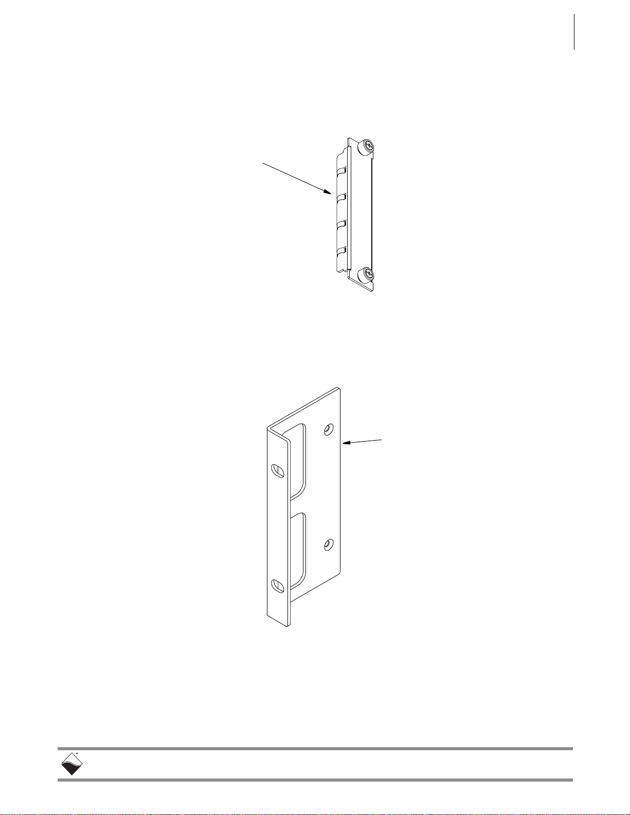
2.4.2.2 DNR-IOFILLER, DNRBRACKET, &
DNR- I/O
Board
Drawings
The following section provides drawings for the DNR-IO-FILLER,
DNR-BRACKET, and DNR- I/O board extraction lever as found in DNR-X-1G
systems.
Figure 2-6. Optional DNR-IO-Filler Panel for Empty Slots
Figure 2-7. DNR-BRACKET Reversible Mounting Bracket
Page 20

DNR-X-1G Series RACKtangle and HalfRACK Systems
October 2018 www.ueidaq.com
508.921.4600
© Copyright 2018
United Electronic Industries, Inc.
Lift Lever
to eject
board from
backplane
connector
Press lever
down to
insert board
into
backplane
connector
DNR Backplane Connector
Chapter 2 12
The DNR-12-1G Series RACKtangle System
Figure 2-8. DNR Board Ejection/Insertion Lever Operation
Page 21

DNR-X-1G Series RACKtangle and HalfRACK Systems
October 2018 www.ueidaq.com
508.921.4600
© Copyright 2018
United Electronic Industries, Inc.
Chapter 2 13
The DNR-12-1G Series RACKtangle System
2.4.3 DNR-12-1G
Cooling Air
Flow
As shown below in Figure 2-9, cooling air is drawn into the rear of the enclosur e
via four fans, routed forward over the electronic circuit boards, up to the top of
the enclosure, and then out the top rear of the enclosure. The system is
designed to maintain positive pressure cooling within the enclosure at all times.
Figure 2-9. DNR-12 Air Flow
Two sensors mounted on the backplane over the Power Module and over the
CPU board continuously monitor internal temperatures, turning fans on if the
internal temperature exceeds 45°C, off if it falls below 45°C, and shutting down
power if a high limit is exceeded.
Page 22

DNR-X-1G Series RACKtangle and HalfRACK Systems
October 2018 www.ueidaq.com
508.921.4600
© Copyright 2018
United Electronic Industries, Inc.
SD Card
USB B
USB A
NIC 1
NIC 2
Sync/Reset
RS-232
3.3
24
COM
USRR/W
PG
POWER
Module 1
Module 2
Module 3
Module 4
Module 5
Module 6
CPU/NIC
Buffer
Module 7
Module 8
Module 9
Module 10
Module 11
Module 12
Module
(dual width)
DNR-POWER-DC
Typical
I/O Board
Serial Port
Connector
Status
LEDs
NIC1 Port
NIC2 Port
Temp1 Sensor (on backplane)Temp0 Sensor (on backplane)
Status
LEDs
DB
Connector
V
in
1.5V
User
Overtemp
24V
3.3V
I
in
I/O
Attention
24V
3.3V
(7-12)
(1-6)
Power
Conn.
PowerDNR
PowerDNR
Fan
Switch
0n/off
Power
DB-9
ATT Indicates error when red
R/W Flashes when bus is active
COM Flashes when SD Card is read/written
PG Indicates presence of valid power input
LEDs
DC/DC Module
(Single Slot Model)
USB 2.0
USB 2.0
Controller
DNR-CPU-1000/-XX
CPU/NIC Module
PowerDNR
Slave Port
Port
Sync Conn/
RESET
SD Card
Slot
Chapter 2 14
The DNR-12-1G Series RACKtangle System
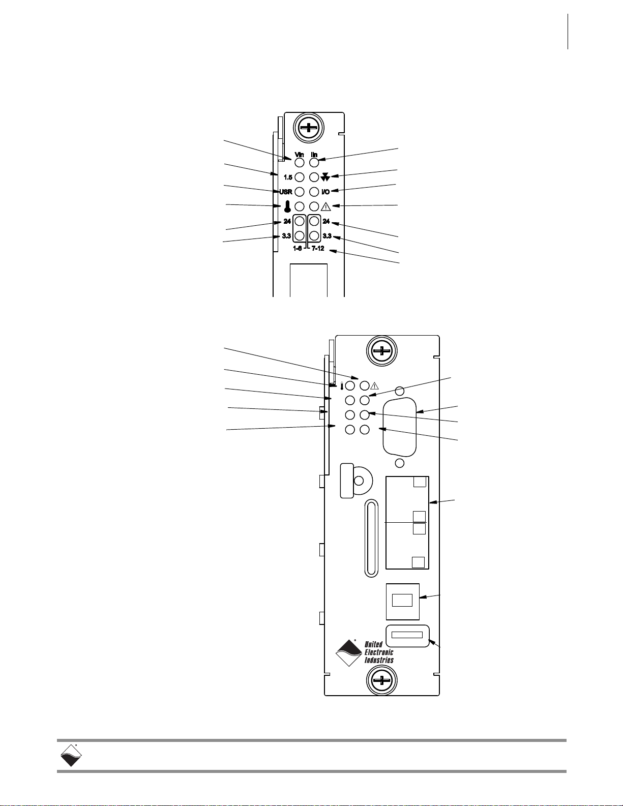
2.5 DNR-12
Power, NIC/
CPU, and I/O
Boards LEDs
& Controls
DNR-12-1G LED indicators are illustrated in Figure 2-10.
The power , CPU, and I/O board LEDs are individu ally described in Figure 2-11,
Figure 2-12, and Figure 2-13 respectively.
Figure 2-10. DNR-12-1G System Front Panel Arrangement
Page 23
DNR-X-1G Series RACKtangle and HalfRACK Systems
October 2018 www.ueidaq.com
508.921.4600
© Copyright 2018
United Electronic Industries, Inc.
Input Voltage OK/Error
1.5VDC OK/Error
User Controlled/Off (default)
LED ON/Off means:
Input Current OK/High
Fans On/Off
I/O Circuit OK (flashes 1/sec))
LED ON/OFF means:
24VDC OK/Error -- Modules 7-12
3.3VDC OK/Error -- Modules 7-12
24VDC OK/Error -- Modules 1-6
3.3VDC OK/Error -- Modules 1-6
When flashing, module needs
Temp High/OK
Module Groups
attention
SD Card
USB B
USB A
NIC 1
NIC 2
Sync/Reset
RS-232
3.3
24
COM
USRR/W
PG
When Flashing,
Read/Write Activity
Serial Comm. Activity
Power Good
Module Needs Attention
Note: On a UEIPAC CPU/NIC module,
the LEDs are user-programmable.
Temp High/OK
USB 2.0 Controller Port
Type A Connector
USB 2.0 Slave Port
Type B Connector
(reserved for future use)
(reserved for future use)
Ethernet Ports
NIC1 (Main),
Serial Port
User Controlled/Off
3.3VDC OK/Error
24VDC OK/Error
NIC2 (Secondary)
The DNR-12-1G Series RACKtangle System
Figure 2-11. DC Power Module LEDs
Chapter 2 15
Figure 2-12. DNR-CPU-1000/-XX Module LEDs
Page 24

DNR-X-1G Series RACKtangle and HalfRACK Systems
October 2018 www.ueidaq.com
508.921.4600
© Copyright 2018
United Electronic Industries, Inc.
Ready (Power ON)
Status
The DNR-12-1G Series RACKtangle System
Figure 2-13. Typical I/O Module LEDs
Chapter 2 16
Page 25

DNR-X-1G Series RACKtangle and HalfRACK Systems
October 2018 www.ueidaq.com
508.921.4600
© Copyright 2018
United Electronic Industries, Inc.
Chapter 2 17
The DNR-12-1G Series RACKtangle System
2.6 DNR-POWER-
DC Module
The DNR-POWER-DC Module is a dedicated DC/DC source and control
module available only for use with a PowerDNR rack enclosure. It is always
mounted in the leftmost slot of the DNR chassis and is recognized on the
PowerDNR bus with an ID of 0x020 at address 0xA00C0000.
The non-isolated side (NIS) logic complies with full common logic interface (CLI)
implementation. The key features of the DNR-POWER Module are:
• Input power — 9-36 VDC 80W maximum, protected by resettable fuses
and EMI chokes
• Power supply on/off switch (with guard)
• Output power sources (all with greater than 90% efficiency)
24V, 1A (24W)
3.3V, 5A (16.5W, including the 2.5V derived voltage)
2.5V, 3A (derived from 3.3V source)
1.5V, 5A, (7.5W, including the 1.2V derived voltage)
8V, 0.5A (4W for fans)
• DC/DC for 24V , 3.3V , and 1.5V are synchron ized from the single spreadspectrum clock source in the CPU/NIC Module for lower EMI noise level
• Fan control (Forced ON) and status ON/OFF
• Monitoring and LED indicators (1% accuracy, 0.25Hz update rate)
for:
– All output voltages
– Input current for the 9-36VDC for the DNR Enclosure
– All voltages from the NIC Module (24V, 3.3V, 2.5V)
– Temperature of the DNR backplane (2 sensors)
• Onboard FPGA logic chip is CYCLONE EP1C3/C6T144
• TI MSP4300 microcontroller used for logic reprogramming
• Input-Output connector is a 128-pin component that provides 9-36VDC
for all modules from an external power source
Page 26

DNR-X-1G Series RACKtangle and HalfRACK Systems
October 2018 www.ueidaq.com
508.921.4600
© Copyright 2018
United Electronic Industries, Inc.
Ejection Lever
On/Off Switch
Power
Connector
Indicating LEDs
Grounding
Fingers
(hidden)
Chapter 2 18
The DNR-12-1G Series RACKtangle System
Figure 2-14. DNR-POWER-DC Module
Page 27

DNR-X-1G Series RACKtangle and HalfRACK Systems
October 2018 www.ueidaq.com
508.921.4600
© Copyright 2018
United Electronic Industries, Inc.
3.3V DC/DC
3.3V DC/DC
3.3V DC/DC
2.5V LDO
1.5V DC/DC
1.2V LDO
24V DC/DC
FAN3-4 CONTROL
8V FAN DC/DC
24-bit ADC (LTC2498) 13 sources: +2.5V, +2.5VNIC, 3.3V, +3.3VNIC,
+24Vm +24VNIC, +VIN, +1.5V, +1.2V, +8V FAN, I
in
,
TEMP1 (TCPOS), TEMP2 (TCNEG). Voltage sources use 1:23.1
dividers on the front end, except for the Vin, which uses a 1:45.3
divider.
Standard NIC-logic plus:
Access to ADC data readings
Fan 1-2 and 3-4 ON/OFF control
Fan ON/OFF status
12 LEDs ON/OFF control
LED block – 12 status LEDs
Input Current
Monitor
+2.5V NIC
DNR Bus Connector
+3.3V NIC
+24V NIC
TEMP1
TEMP2
FAN1-2 CONTROL
Input Voltage Source
9-36 VDC @ 80 W max.
1.2V
1.5V
24V
3.3V
2.5V
24V
8V
Vin
Chapter 2 19
The DNR-12-1G Series RACKtangle System
A functional block diagram of the DNR-POWER-DC Module is shown in
Figure 2-15 below.
Figure 2-15. Functional Block Diagram of DNR-POWER-DC Module
As shown in Figure 2-15, the DNR-POWER-DC Module operates as follows:
A 9-36 VDC voltage input (Vin) from an external source is connected to the
board through a replaceable slow-blow fuse. The board monitors the input
current and passes Vin to the DNR bus as Vout.
Vout also is connected to DC/DC converters that produce 24 VDC, 3.3 VDC and
1.5 VDC output voltages, which are also placed on the DNR bus. Both 3.3 and
1.5 VDC voltages are connected to low dropout regulator s that, in turn, generate
the 2.5 VDC and 1.2 VDC output voltages on the bus. The 24 VDC source is fed
to a low dropout regulator that produces 8 VDC to drive the cooling fans (through
fan controller chips).
Page 28

DNR-X-1G Series RACKtangle and HalfRACK Systems
October 2018 www.ueidaq.com
508.921.4600
© Copyright 2018
United Electronic Industries, Inc.
CPU/NIC
PULLUPS
SLOTS
6...B
SLOTS
0..5, C
PWR
ADDR/CTRL
CLOCKS
TEMP1
TEMP0
2.5V
3.3V, 24V
1.2V AND 1.5V
2.5V,3.3V
ADDR/CTRL
CLOCKS
6
6
DNR-BUFFER/
CLOCK DIST.
DATA BUS
DNR-POWER-DC
PULLUPS
I/O
I/O
Chapter 2 20
The DNR-12-1G Series RACKtangle System
The input current and all output voltages, including the +2.5, +3.3, and +24 VDC
from the NIC module, plus signals from the two temperature sensors mounted
within the enclosure, are input to a 24-bit delta-sigma A/D converter. Except for
Vin, the voltage sources use 1:23.1 divide rs on the front end. Vin uses a 1:45.3
divider.
Figure 2-16 shows the interaction of modules within a DNR-12 enclosure when
the DNR-BUFFER module is used.
Figure 2-16. Functional Block Diagram of DNR-12 Enclosure
As shown above, the I/O slots are divided into two groups: 0 to 5 and 6 to 0xB.
0xC for the DC Power Module is included with the 0 to 5 group. The DNRBUFFER board is located at the center of the enclosure, which is also at the
center point of the ADDR/CTRL bus. The DNR-CPU-1000 module is also
located at the center of the enclosure and the center of the data b us to minimize
bus delays. The CPU addresses I/O Boards and transmits clock ticks through
the Buffer Board, which controls the Addr/Ctrl and clock lines to the modules.
Temperature sensors monitor temperatures within the enclosure above the
DNR-POWER-DC module and the DNR-CPU module.
Page 29

DNR-X-1G Series RACKtangle and HalfRACK Systems
October 2018 www.ueidaq.com
508.921.4600
© Copyright 2018
United Electronic Industries, Inc.
Front Panel Isometric of Carrier
(holds two circuit boards – CPU and NIC)
SD Card
USB B
USB A
NIC 1
NIC 2
Sync/Reset
RS-232
3.3
24
COM
USRR/W
PG
DB-9 Connector
for serial port
Diagnostic
Port - NIC2
Primary Ethernet
Port - NIC1
USB A
USB B
Chapter 2 21
The DNR-12-1G Series RACKtangle System
2.7 DNR-CPU/NIC Module
The DNR-CPU/NIC Core Module (DNR-CPU-1000, DNR-CPU-1000-02, or
DNR-CPU-1000-03) occupies two slots of a DNR-X-1G RACKtangle
enclosure.
The DNR-CPU/NIC Core module consists of a Freescale (formerly Motorola)
MPC8347 or MPC8347E 32-bit 400 MHz CPU and per ipheral devices (USB 2.0,
RS-232, NIC, SD, etc) for use with a Gigabit Ethernet communication network
and an internal 66 MHz 32-bit common logic interface bus. The NICs are cop per
(1000BaseT) interfaces. The module has an RS-232 port used for co nfiguration
and also two USB 2.0 ports (controller and slave) for general purpose use (not
implemented yet). LEDs on the front panel of each module indicate the current
operating status of the device.
Figure 2-17. DNR-X-1G Series Core Module (CPU/NIC)
Page 30

DNR-X-1G Series RACKtangle and HalfRACK Systems
October 2018 www.ueidaq.com
508.921.4600
© Copyright 2018
United Electronic Industries, Inc.
MAC
MAC
PPC 8347
DC/DC
9-36V DC Input
Power Out
Power In
SD Card RS-232
32-bit 66-MHz bus
RJ-45
RJ-45
PHY
PHY
RTC
DDR2
FLASH
MII
1000-BASE-T
MII
FPGA
USB 2.0
USB 2.0
,(((QHWZRUNV\QFKURQL]DWLRQVXSSRUWRQDQG&38YHUVLRQV
Chapter 2 22
The DNR-12-1G Series RACKtangle System
2.7.1 Device
Architecture
of DNR Core
Module
Figure 2-17 shows the architecture of the DNR-CPU-1000 Series Core
Modules:
Figure 2-18. FreeScale PowerPC CPU/NIC Controller Architecture
The core of the system is a Freescale PowerPC MPC834 7 or MPC8347E 32-bit
400 MHz processor, which controls the following components:
Table 2-2 Components in PowerDNR Core Module (DNR-CPU-1000 Series)
Item Description
NIC1:
Primary Network
Interface MII Port
NIC2:
Diagnostic Network
Interface MII Port
RS-232 Port The RS-232 port provides a serial communication link between the DNR-X-1G
USB 2.0 Dual Port
(Controller and Slave)
32 MB or 128 MB
Flash Memory
1
The NIC1 port provides communication between the DNR system and the
primary LAN network.
The NIC2 port provides access to the DNR system for monitoring system health
during operation, using a separate diagnostic port. This port may also be
assigned as the primary Ethernet port if NIC1 is not available for use.
system and a standard RS-232 terminal.
The USB A and B ports are not supported on DNR-X-1G (hosted) systems
(only supported on UEIPAC, UEISIM, UEIModbus, and UEIOPC-UA
deployments).
DNR-X-1G (-00/-01) systems provide 32 MB of flash memory (DNR-CPU-
1000).
DNR-X-1G-02 systems provide 32 MB of flash memory (DNR-CPU-1000-02).
DNR-X-1G-03 systems provide 128 MB of flash memory (DNR-CPU-1000-03).
Page 31

DNR-X-1G Series RACKtangle and HalfRACK Systems
October 2018 www.ueidaq.com
508.921.4600
© Copyright 2018
United Electronic Industries, Inc.
The DNR-12-1G Series RACKtangle System
Table 2-2 Components in PowerDNR Core Module (DNR-CPU-1000 Series)
Item Description
Chapter 2 23
128 MB or 256 MB
of SDRAM
SYNC Port
1
2
IEEE-1588
Synchronization
Support
SD Card
2
1
DNR-X-1G (-00/-01) systems provide 128 MB of RAM (DNR-CPU-1000).
DNR-X-1G-02 systems provide 256 MB of RAM (DNR-CPU-1000-02).
DNR-X-1G-03 systems provide 256 MB of RAM (DNR-CPU-1000-03).
A high-speed system-to-system synchronization connector permits triggers or
clocks to be shared among multiple systems. Two systems may be connected
together directly and larger groups m ay use the SYNC in terface to shar e timing
signals among many racks and systems.
The trigger and clock inputs will accept signals from standard digital logic that is
powered in the range of 3.3 V to 5 V. The inputs also have internal pull-up
resistors to an internal 5 V supply , making the inputs also compatible with a lowside drive open-collector output. The Sync and trigger outputs have 5 V logic
levels. The sync connector’s ground and 5 V power connections are provided
by its own isolated DC-DC converter.
DNR-X-1G-02 and DNR-X-1G-03 systems implement IEEE-1588
synchronization in hardware. (DNR-CPU-1000-02 and DNR-CPU-1000-03)
A slot for inserting a Secure Digital card.
SD cards are not supported on DNR-X-1G systems.
(SD cards are only supported on UEIPAC, UEISIM, UEIModbus, and UEIOPCUA deployments, uses EXT3 as filesystem for the system partition and
optionally FAT32 for one or more data partitions on the UEIPAC-based standalone systems only).
1
Solid state hard drive
Optional solid state hard drive (only supported on UEIPAC, UEISIM,
UEIModbus, and UEIOPC-UA deployments).
LEDs The operating conditions indicated by the front panel LEDs are described in
Figure 2-11 on page 15 through with Figure 2-13 on page 16.
Watchdog T imer With
Real-time Clock
The DNR-X-1G system includes a watchdog timer with battery backed-up realtime clock.
(Battery Backed)
1.The SD card, SSDs, RAM and flash memory are not user-accessible for PowerDNA applications (hosted
deployment). Portions of RAM and flash are available for UEIPAC-based systems (stand-alone deployment).
See UEIPAC documentation for more information.
2.1PPS and IEEE-1588 synchronization support is described in the PowerDNx 1PPS Sync Interface Manual.
Not all components are available for control from the CPU. The CPU can
program flash memory, set the LEDs, set up the watchdog timer, set the realtime clock and use 256 bytes of backed-up memory in th e watchdog timer chi p.
All functions are available at the firmware level only (described in iom.c/iom.h).
Page 32

DNR-X-1G Series RACKtangle and HalfRACK Systems
October 2018 www.ueidaq.com
508.921.4600
© Copyright 2018
United Electronic Industries, Inc.
Chapter 2 24
The DNR-12-1G Series RACKtangle System
2.8 DNR-Buffer Module
The DNR-BUFFER Module provides buffering between the CPU and I/O board
address/control/clock lines, which functions as described in Figure 2-16.
Although the module may not always be required, it is included to provide an
extra margin of safety against loss of data.
2.9 DNR I/O Boards
All standard cube-based PowerDNA I/O boards are also available as rackbased PowerDNR boards. A typical PowerDNR board is functionally identical to
its corresponding PowerDNA version. The only difference between them is the
physical mounting arrangement. PowerDNR modules are designe d for insertion
into the DNR-6 or DNR-12 enclosure; PowerDNA modules can be inserted only
into a PowerDNA Cube.
Refer to the datasheets and user manuals for detailed electrical specifications,
board descriptions, and user instructions for I/O boards. These documents are
available on the UEI website at www.ueidaq.com.
2.10 DNR-12-1G
DC Power
Table 2-1 lists the DC power threshold specifications for DNR-12-1G 12-slot
RACKtangle systems.
Thresholds
Table 2-1 DC Power Thresholds for DNR-X-1G RACKtangle and HalfRACK systems
Logic power
supply
Analog power
supply
Fan power
supply
On-board
DC/DCs that
use input
power
Backplane
Power Rail
Voltages
+3.3V, +2.5V,
+1.5V, +1.2V
+24V 8.5 - 7.8 Analog power supply is
+12V 8.5 - 8.4
+VIn 7.8-8.8 - 7.5-8.5 Varies with board type.
Turn-on
Voltage, V
1
7.5 7.2
(When Vin is
below 7.2V , a
voltage reset
puts all
boards into
reset mode.)
Reset
Voltage, V
Turn-off
Voltage, V
2
7.0 Supplies power to all CPUs
and FPGAs. DNR can communicate with Ethernet
when CPU is functional
used as a regulated source
for on-board DC/DCs on
most boards
Notes
1. Turn-on, V: The value of Vin at which the corresponding DC/DCs are turned on.
2. Turn-off, V: The value of Vin at which the corresponding DC/DCs are turned off.
NOTE: A DNR-12- 1G CPU/NIC core module consumes only 70mW whe n Vin is
below 7V.
Page 33

DNR-X-1G Series RACKtangle and HalfRACK Systems
October 2018 www.ueidaq.com
508.921.4600
© Copyright 2018
United Electronic Industries, Inc.
The DNR-6-1G Series HalfRACK System
Chapter 3 25
Chapter 3 The DNR-6-1G Series HalfRACKSystem
This chapter provides the following information about the DNR-6-1G Series
HalfRACK
NOTE: For the list of product versions available for the DNR-6-1G Series
system:
• PowerDNR DNR-6-1G System Overv iew (Section 3.1)
• DNR-6-1G Specifications (Section 3.2)
• DNR-6-1G Key Features (Section 3.3)
• DNR-6-1G HalfRACK Enclosure (Section 3.4)
• DNR-6 Power, NIC/CPU, and I/O Boards LEDs & Controls (Section 3.5)
• DNR-6-1G DNR-POWER-DC Module (Section 3.6)
• DNR-6-1G DNR-CPU/NIC Module (Section 3.7)
• DNR-6-1G DNR-IO-Modules (Section 3.8)
• DNR-6-1G DC Power Thresholds (Section 3.9)
HalfRACK systems, refer to Section 1.2 on page 3.
3.1 PowerDNR DNR-6-1G System Overview
UEI DNR-6-1G HalfRACK systems are identical to the DNR-12-1G systems
except for the size of the enclosure and the number and ord er of I/O boards that
can be accepted. All standard DNA- Cube I/O boards are available in
DNR- RACK versions for use in DNR-6-1G systems.
Figure 3-1. Typical DNR-6-1G HalfRACK System
Page 34

DNR-X-1G Series RACKtangle and HalfRACK Systems
October 2018 www.ueidaq.com
508.921.4600
© Copyright 2018
United Electronic Industries, Inc.
Chapter 3 26
The DNR-6-1G Series HalfRACK System
A standard DNR-6-1G rack system consists of the following modules:
• One or more DNR-6 rack mounted enclosure(s)
• DNR-POWER-DC Power Module (one for each enclosure)
• DNR-CPU-1000 or DNR-CPU-1000-XX Module
(Freescale MPC8347 or MPC8347E CPU and 1-GB Ethernet
1000 Base-T Network Interface Module — one for each enclosure)
• Optional DNR-IO-FILLER panels (one for each unused I/O slot)
Note: These slot covers are optional and not included in the price of the
rack.
• DNR-PSU-100 100-Watt, 120/230 VAC to +24 VDC External Power
Supply (one for each enclosure) with cable and Molex connector for
plug-in to the DNR-POWER-DC Module front panel.
To configure a complete data acquisition system, insert up to 6 DNR I/O boards
into each PowerDNR rack enclosure. I/O boards may be specified in any
combination of UEI’s I/O boards.
All standard PowerDNA accessories are also available for use in a PowerDNR
rack-mount system.
NOTE: For detailed descriptions of all I/O boards and accessories available for
DNR-X-1G systems, refer to www.ueidaq.com.
UEI stand-alone systems (UEIPAC, UEISIM, UEIModbus, and UEIOPCUA
deployments) are also available for use with DNR-6-1G RACK systems:
• UEIPAC 600R - Programmable Automation Controller
• UEISIM 600R - Simulink / Simulink Coder Target
• UEIModbus 600R - Modbus TCP-based Controller
• UEIOPCUA 600R - OPC-UA Serv er, accessed by any OPC-UA client
Page 35

DNR-X-1G Series RACKtangle and HalfRACK Systems
October 2018 www.ueidaq.com
508.921.4600
© Copyright 2018
United Electronic Industries, Inc.
Standard Interfaces
To Host Computer Two independent 1000Base-T Gigabit Ethernet
ports (100/10Base-T compatible)
Distance from host 100 meters, max
Cong/General RS-232, 9-pin “D”
Sync Custom cable to sync multiple racks
I/O Slots Available
DNR-6-1G 6 slots
Data transfer and communications rates
Ethernet data
transfer rate
20 megabytes per second
Analog data
transfer rate
up to 6 megasample per sec (16-bit samples)
DMAP I/O mode update 1000 I/O channels (analog and/or digital)
in less than 1 millisecond, guaranteed
Processor
CPU Freescale 8347, 400 MHz, 32-bit
Memory 128 MB (not including on-board Flash)
Status LEDs Power supplies within spec, One second system
heart-beat, Attention, Read/Write, Power, Communications Active
Environmental
Temp (operating) Tested to -40 °C to 70 °C
Temp (storage) -40 °C to 85 °C
Humidity 0 to 95%, non-condensing
Vibration
(IEC 60068-2-64) 10–500 Hz, 3 g (rms), Broad-band random
(IEC 60068-2-6) 10–500 Hz, 3 g, Sinusoidal
Shock
(IEC 60068-2-27)
50 g, 3 ms half sine, 18 shocks at 6 orientations;
50 g, 11 ms half sine, 18 shocks at 6 orientations
MTBF 130,000 hours
Physical Dimensions
DNR-6 series 5.25” x 6.2” x 10.5” (3U in a 19” rack)
Power Requirements
Voltage 9 - 36 VDC (AC adaptor included)
Fuse Internal 10 A
Power Dissipation 13 W at 24 VDC (not including I/O boards)
Power Monitoring
I/O board power All internal power supplies monitored to ±1% ac-
curacy. All PS voltages may be read by host. LED
annunciators indicate out of range
Input current Monitored by host, LED indicates overcurrent
Input voltage Monitored by host, LED indicates out of range
Chapter 3 27
The DNR-6-1G Series HalfRACK System
3.2 DNR-6-1G
The technical specifications of the DNR-6-1G system are listed below.
Specifications
Figure 3-2. DNR-6-1G Technical Specifications
Page 36

DNR-X-1G Series RACKtangle and HalfRACK Systems
October 2018 www.ueidaq.com
508.921.4600
© Copyright 2018
United Electronic Industries, Inc.
Easy to Configure and Deploy
Over 30 different I/O boards available
Over 5 quadrillion possible configurations
Gigabit Ethernet based (100/10Base-T compatible)
Bracket kit for mounting to wall or in 19” racks
Industrial quality rubber feet for solid table-top mounting
Passive backplane ensures high MTBF and Low MTTR
Standard “Off-the-shelf” products and delivery
True Real-time Performance
1 msec updates guaranteed with 1000 I/O
Up to 6 million samples per second
Use QNX, RTX, 7Y8PSLT
Flexible Connectivity
1000Base-T with Cat-5 cable
Supports WIFI / GSM / Cell networks
Compact Size:
5.25” x 6.2” x 10.5”
150 analog inputs per rack
192 analog outputs per rack
288 digital I/O bits per rack
48 counter/quadrature channels per rack
72 ARINC-429 channels per rack
24 RS-232/422/485 ports per rack
Low Power:
Less than 13 watts per typical rack (not including I/O)
AC, 9-36 VDC or battery powered.
Standalone Modes
Upgradeable to UEI1"$ 600R
Upgradeable to UEI4*. 600R
Upgradeable to UEIModbus 600R
Rugged and Industrial:
Solid Aluminum construction
130,000 hour MTBF
Operation tested from -40°C to +70°C
Vibration tested to 3 g, (operating)
Shock tested to 50 g (operating)
All I/O isolated from rack and host PC.
Outstanding Software Support
Windows, Linux, RT Linux, Windows RT, RTX VXworks and
QNX operating systems
VB, VB .NET, C, C#, C++
MATLAB, LabVIEW, OPC, Active X
Chapter 3 28
The DNR-6-1G Series HalfRACK System
3.3 DNR-6-1G
The following table is a list of the key features of a DNR-6-1G system.
Key Features
Figure 3-3. DNR-6-1G HalfRACK Product Features
Page 37

DNR-X-1G Series RACKtangle and HalfRACK Systems
October 2018 www.ueidaq.com
508.921.4600
© Copyright 2018
United Electronic Industries, Inc.
Backplane
Rubber feet (4)
for tabletop mounting
Guides for Power,
CPU, and I/O
modules
Cooling Fans
Carrying
Handle
with 2 temp.
sensors
Chapter 3 29
The DNR-6-1G Series HalfRACK System
3.4 DNR-6-1G HalfRACK Enclosure
3.4.1 DNR-6-1G
Enclosure
This section describes the DNR-6-1G chassis and provides an overview of
common components included in every DNR-6-1G system.
The enclosure is a rigid mechanical structure with complete EMI shielding. A
convenient carrying handle is also provided for portability. Unused slots can be
filled with blank filler panels. The DC/DC power module provides output voltages
of 24, 3.3, 2.5, 1.5, and 1.2 VDC for the logic/CPU and 8 VDC to power the three
cooling fans.
Figure 3-4. Typical HalfRACK DNR-6 Enclosure (Exploded View)
NOTE: Note that the rightmost module (I/O board 6) is 2-slots wide (to
accommodate future designs and/or custom boards).
Also note, rubber feet are supplied for desktop or tabletop mounting. If
rack mounting is desired, UEI recommends using a shelf for mounting in
a 19 inch enclosure. Refer to Section 4.7 on page 56 for more
information about mounting and field connections.
Page 38

DNR-X-1G Series RACKtangle and HalfRACK Systems
October 2018 www.ueidaq.com
508.921.4600
© Copyright 2018
United Electronic Industries, Inc.
DNR-POWER-DC DNR-CPU-1000/-XX DNR-IO-FILLER
up to 6 I/O Boards
Chapter 3 30
The DNR-6-1G Series HalfRACK System
3.4.2 DNR-6-1G
Enclosure
Common
Components
Each DNR-6-1G chassis contains a power board (DNR-POWER-DC) with
status indicators and an external ON/OFF switch , an d a CPU bo ar d with a
dedicated GigE CPU and two Network Interface Control (NIC) ports, one for
controlling up to 6 I/O boards mounted in the enclosure and another for
diagnostics functions. Front-loading slots allow I/O boards to be quickly and
easily installed and removed, if needed.
Up to 6 DNR I/O boards can be installed in the chassis; DNR I/O boards are
functionally identical to the corresponding Cube-based DNA boards. The only
differences between RACK and Cube I/O boards are the mounting hardware.
The DNA version I/O boards are designed to stack in a Cube chassis. T he DNR
version I/O boards are designed to plug into the backplane of a RACK chassis.
Figure 3-5 Typical PowerDNR DNR-6 Board Placement
Table 3-1 Components in PowerDNR DNR-6 Enclosure
Item Description
DNR-POWER-DC One isolated DC/DC Power Module/Power Monitor with status indicators, a local
on/off switch, and 4-pin Molex Power-In connector. (Refer to “DNR-POWER-DC
Module” on page 17 for more information)
DNR-CPU-1000,
DNR-CPU-1000-02,
DNR-CPU-1000-03
PowerDNR I/O
Boards
DNR-BP-6 One backplane with two temperature sensors (see Figure 3-4 for diagram)
DNR-IO-FILLER Blank filler panels for all unused slots (optional / not included in price of rack)
Fans Three 8-volt cooling fans mounted on the rear of the enclosure (see Figure 3-4
One dual-slot CPU/NIC module with status indicators, two Ethernet connectors
(Main and Diagnostic Ports), sync connector , reset pushbutton , SD card slot, USB
controller/slave ports (future use), and a DB-9 connector for a serial port
(Refer to “DNR-CPU/NIC Module” on page 21 for a detailed description)
Up to 6 front pull-out I/O boards (DNR boards are functionally identical to
PowerDNA Cube I/O boards but designed for installation in a DNR rack
enclosure). (Refer to Section 3.8 for more information)
and Section 3.4.3 for air flow diagram)
All UEI PowerDNA modules are available in both PowerDNA and Power DNR
package designs.
Page 39

DNR-X-1G Series RACKtangle and HalfRACK Systems
October 2018 www.ueidaq.com
508.921.4600
© Copyright 2018
United Electronic Industries, Inc.
Chapter 3 31
The DNR-6-1G Series HalfRACK System
3.4.2.1 Physical
Addressing of
DNR-6-1G
Components
A feature of the DNR-6-1G design is that the address of a module is determined
by the position of the module within the enclosure, numbered from left to right. A
typical module address is:
0xA00nxxxx
where A00 is the BASE address
n is the module position number starting from 0 at the left
xxxx is the address of the module
With this addressing method, the address of a given I/O board (module)
automatically changes if you move it from one position to another within the
enclosure.
The slots or module positions for the DNR-6-1G are numbered as follows (l eft to
right:
Physical Position Position Number Module Description
10xCPOWER-DC
20xD
0xE
POWER-1GB
CPU/NIC
3 0x0 Module1
4 0x1 Module2
5 0x2 Module3
6 0x3 Module4
7 0x4 Module5
8 0x5 Module6
Page 40

DNR-X-1G Series RACKtangle and HalfRACK Systems
October 2018 www.ueidaq.com
508.921.4600
© Copyright 2018
United Electronic Industries, Inc.
Chapter 3 32
The DNR-6-1G Series HalfRACK System
3.4.3 DNR-6-1G Cooling Air Flow
As shown in Figure 3-6 below , cooling air is drawn into the rea r of the enclosure
via three fans, routed forward over the electronic circuit boards, up to the top of
the enclosure, and then out the top rear of the enclosure. The system is
designed to maintain positive pressure cooling within the enclosure at all times.
Figure 3-6. DNR-6 Air Flow
Two sensors mounted on the backplane monitor internal temperatures
continuously, turning fans on if the internal temperature exceeds 45°C, off if it
falls below 45°C, and shutting down power if a high limit is exceeded.
Page 41

DNR-X-1G Series RACKtangle and HalfRACK Systems
October 2018 www.ueidaq.com
508.921.4600
© Copyright 2018
United Electronic Industries, Inc.
SD Card
USB B
USB A
NIC 1
NIC 2
Sync/Reset
RS-232
3.3
24
COM
USRR/W
PG
POWER
CPU/NIC
Module 1
Module 2
Module 3
Module 4
Module 5
Module
DNR-POWER-DC
Typical
I/O Board
Serial Port
Connector
Status
LEDs
NIC1 Port
NIC2 Port
Temp1 Sensor
Temp0 Sensor (on backplane)
Status
LEDs
DB
Connector
Vin
1.5V
User
Overtemp
24V
3.3V
Iin
I/O
Fan
24V
3.3V
(7-12)
(1-6)
Power
Conn.
PowerDNR
PowerDNR
1.2V
Switch
0n/off
Power
DB-9
ATT Indicates error when red
R/W Flashes when bus is active
COM Flashes when SD Card is read/written
PG Indicates presence of valid power input
LEDs
DC/DC Module
(Single Slot Model)
USB 2.0
USB 2.0
Controller
DNR-CPU-1000/-XX
CPU/NIC Module
PowerDNR
Slave Port
Port
Sync
Conn/PB
SD Card
Slot
Module 6
(dual width)
Chapter 3 33
The DNR-6-1G Series HalfRACK System
3.5 DNR-6 Power ,
NIC/CPU, and
I/O Boards
LEDs &
Controls
DNR-6-1G LED indicators are illustrated in Figure 3-7.
Note that modules used in both DNR-6 and DNR-12 systems are identical,
except that the DNR-6 enclosure only accepts six I/O boards. The power , CPU,
and I/O board LEDs are individually described in “DNR-12 Power, NIC/CPU, and
I/O Boards LEDs & Controls” on page 14.
Figure 3-7. DNR-6-1G System Front Panel Arrangement
Page 42

DNR-X-1G Series RACKtangle and HalfRACK Systems
October 2018 www.ueidaq.com
508.921.4600
© Copyright 2018
United Electronic Industries, Inc.
The DNR-6-1G Series HalfRACK System
Chapter 3 34
3.6 DNR-6-1G
DNR-POWERDC Module
3.7 DNR-6-1G
DNR-CPU/NIC
Module
3.8 DNR-6-1G
DNR-IOModules
Refer to “DNR-POWER-DC Module” on page 17 in Chapter 2 for a detailed
description of the DNR-POWER-DC Module. This unit is used in both the DNR6 and the DNR-12 systems.
The DNR-CPU/NIC Module (DNR-CPU-1000, DNR-CPU-1000-02, or
DNR-CPU-1000-03, depending on the product version) contains a PowerPC
8347 or 8347E CPU and associated Network Interface Control (NIC) logic that
controls all Ethernet communication functions. The DNR-CPU/NIC includes a
dual 1-GB Ethernet module. This unit is used in both the DNR-6 and the DNR12 systems.
Refer to “DNR-CPU/NIC Module” on page 21 in Chapter 2 for a detailed
description of the DNR-CPU-1000/-XX Module.
All standard cube-based PowerDNA I/O boards are also available as rackbased PowerDNR boards. A typical PowerDNR board is functionally identical to
its corresponding PowerDNA version. The only difference between them is the
physical mounting arrangement. PowerDNR modules are designe d for insertion
into the DNR-6 or DNR-12 enclosure; PowerDNA modules can be inserted only
into a PowerDNA Cube.
Refer to the datasheets and user manuals for detailed electrical specifications,
board descriptions, and user instructions for I/O boards. These documents are
available on the UEI website at www.ueidaq.com.
Page 43

DNR-X-1G Series RACKtangle and HalfRACK Systems
October 2018 www.ueidaq.com
508.921.4600
© Copyright 2018
United Electronic Industries, Inc.
Chapter 3 35
The DNR-6-1G Series HalfRACK System
3.9 DNR-6-1G DC
Power
Table 5-1 lists the DC power threshold specifications for DNR-6-1G HalfRACK
systems.
Thresholds
Table 5-1 DC Power Thresholds for DNR-6-1G HalfRACK Systems
Backplane
Logic power
supply
Analog power
supply
Fan power
supply
On-board
DC/DCs that
use input
power
Power Rail
Voltages
+3.3V , +2.5V ,
+1.5V, +1.2V
Turn-on
Voltage, V
1
7.5 7.2
Reset
Voltage, V
(When Vin is
below 7.2V , a
voltage reset
puts all
boards into
reset mode.)
+24V 8.5 - 7.8 Analog power supply is
+12V 8.5 - 8.4
+VIn 7.8-8.8 - 7.5-8.5 Varies with board type
Turn-off
Voltage, V
7.0 Supplies power to all CPUs
2
Notes
and FPGAs. DNR can communicate with Ethernet
when CPU is functional
used as a regulated source
for on-board DC/DCs on
most boards
1. Turn-on, V: The value of Vin at which the corresponding DC/DCs are turned on.
2. Turn-off, V: The value of Vin at which the corresponding DC/DCs are turned off.
A DNR-6-1G CPU/NIC core module consumes only 70mW when Vin is below 7V.
Page 44

DNR-X-1G Series RACKtangle and HalfRACK Systems
October 2018 www.ueidaq.com
508.921.4600
© Copyright 2018
United Electronic Industries, Inc.
Installation and Configuration
Chapter 4 Installation and Configuration
The following installation and configuration topics are included in this chapter:
• Initial Installation Guide (Section 4.1)
• Initial Boot-up (Section 4.2)
• IP Address Overview & Update Procedures (Section 4.3)
• Network Configuration (Section 4.4)
• Troubleshooting (Section 4.5)
• Updating Firmware (Section 4.6)
• Mounting and Field Connections (Section 4.7)
• Wiring I/O Boards (Section 4. 8)
• Repairing (and Upgrading) a DNR System (Section 4.9)
• Configuring a NIC Port for Diagnostic Mode (S ection 4.10)
• Disabling Writes to Flash/EEPROM (NVRAM) (Section 4.11)
Chapter 4 36
4.1 Initial
Installation
Guide
NOTE: Throughout this chapter, several images show just DNR-6 or DNR-12
systems. Unless otherwise noted, each representation applies to both
systems.
This section describes the procedure recommended for performing an initial
hardware and software setup when you first receive a DNR-X-1G system:
• Verify shipment contents, Section 4.1.1
• Install software, Section 4.1.2
• Verify communication over serial port (optionally) / initial boot up,
Section 4.2
• Configure IP addresses (if needed), Section 4.3
• Connect your DNR-X-1G system to your host PC or network switch,
Section 4.4 and Section 4.7 (optionally)
Page 45

DNR-X-1G Series RACKtangle and HalfRACK Systems
October 2018 www.ueidaq.com
508.921.4600
© Copyright 2018
United Electronic Industries, Inc.
Chapter 4 37
Installation and Configuration
4.1.1 Inspect Package
4.1.2 Install Software
Inspect the contents of the shipping package. With a standard DNR-X-1G
system, you should find:
• A DNR-12 or DNR-6 enclosure, preinstalled with a NIC/CPU
(DNR-CPU-1000/-XX) module, DNR-POWER-DC module, blank filler
panels (if specified), plus your selection of I/O boards. A DNR-12 system
also includes a DNR-BUFFER module (not used with a DNR-6).
• A DNA-PSU-180 180-watt (for DNR-12-1G product versions) or
a DNA-PSU-100 100-watt (for DNR-6-1G) universal powerline brick
1
that plugs into an AC outlet and provides 24V DC output. The supply
comes with a power cord for the mains and an adapter cable ending in
a Molex connector for plugging into the DN R-POWER-DC Module.
• DB-9 serial cable for initial hardware configuration and firmware
downloading.
• Cat5e Ethernet cable (7 foot).
• CD-ROM with support software.
This section describes how to load the PowerDNA software suite onto a
Windows- or Linux-based computer (i.e. host PC) and run some initial tests.
The latest PowerDNA or DNR-X-1G support software is online at
www.ueidaq.com/download
; a copy is also on the PowerDNA Software Suite
CD.
A. Software Install: Windows
The PowerDNA CD provides one installer that combines the UEI low-level driver
and UEIDAQ Framework.
Be sure to install third-party applications (such as LabVIEW , MATLAB, or Visual
Studio) before installing the PowerDNA Software Suite. The installer
automatically searches for third-party IDE and testing suites, and adds them as
tools to the suites found.
To install the PowerDNA Software Suite, do the following:
STEP 1: Open the PowerDNA Software Suite installer as an administrator.
You can run the installer from the provided PowerDNA Software Suite CD or
from a downloaded installation from our website.
• T o run the installer from the PowerDNA Software Suite CD, insert the CD into
your CD-ROM drive. Windows should automatically start the PowerDNA
Setup program.
An installer with the UEI logo will open, and then the
PowerDNA Welcome screen should appear.
If this does not happen, run setup.exe from the CD drive:
Start >> Run >> d:\setup.exe >> OK
• To run from a recently downloaded executable from www.ueidaq.com,
right-click the filename, and run as administrator.
1. A larger power supply is required for some configurations. Refer to
UEI.
Page 46

DNR-X-1G Series RACKtangle and HalfRACK Systems
October 2018 www.ueidaq.com
508.921.4600
© Copyright 2018
United Electronic Industries, Inc.
Chapter 4 38
Installation and Configuration
STEP 2: Follow the prompts, and then choose a PowerDNA Software Suite Setup Type.
Unless you are an expert user and have specific requirements, select Typical
Installation and accept the default configuration.
The Software Suite installer automatically installs any required tools and plugins.
If 32-bit Java VM is not detected on the system, Java JRE 1.6.5 for Windows XP
will automatically be installed for PowerDNA Explorer. As an alternative, use the
Custom option to display and ensure that all of the necessary packages are
installed.
• Companion Documentation:
Quick Start Guide, Configuration and Core Module,
I/O Board Manuals, API Programming Guide
• SDK: includes/lib for C/Java, examples, and JRE;
(The SDK is not the UeiDaq Framework)
• PowerDNA Apps: PowerDNA Explorer, MTTTY
• PowerDNA Components (incl. DLL files)
• PowerDNA Firmware
STEP 3: Click Next to continue through the dialogs.
STEP 4: Click Finish to complete the installation.
The Software Suite installs tools needed in later steps, such as MTTTY,
PowerDNA Explorer, and th e low -le ve l dr ive r.
UEIDAQ Framework is also included in the installation and provides the
structure for developing applications under C/C++, C#, VB.NET, ActiveX,
MATLAB, LabVIEW, LabWindows/CVI, OPC, and other programming
languages.
STEP 5: Restart the computer.
NOTE: Because the installation process modifies your Windows registry, you
should always install or uninstall the software using the appropriate
utilities. Never remove PowerDNA software from your PC directly by
deleting individual files; always use the Windows Control Panel
Add/Remove Programs utilit
Software Install: Linux
B.
The PowerDNA_*.tgz file in the CD\Linux folder contains the software package
for Linux. To extract the file to a local directory:
tar -xjvf /path/to/powerdna*.tgz
Follow the instructions in the readme.txt file provided in the tar file.
y.
Page 47

DNR-X-1G Series RACKtangle and HalfRACK Systems
October 2018 www.ueidaq.com
508.921.4600
© Copyright 2018
United Electronic Industries, Inc.
Chapter 4 39
Installation and Configuration
4.2 Initial Boot-up Perform an initial boot in preparation for configuring the network using the
following procedure:
STEP 1: Familiarize yourself with your DNR system front-panel layout. Note that all
connections are made on the front of the unit; no rear access is required in a
rack-mounted configuration.
STEP 2: Optionally, set up communication over the serial port by attaching the serial
cable between the host PC and to the RS-232 port on the front panel of the
DNR-X-1G:
a. Run a serial terminal-emulation program (e.g., MTTTY) on the PC. Any
terminal-emulation program, except HyperTerminal, may be used
(MTTTY, Minicom, TeraTerm, PuTTY, etc.).
b. Verify that COM parameters are set at: 57600 baud, 8 bits, no parity, 1
stop bit.
c. Click Connect in MTTTY, or use the commands on one of the other
terminal-emulation programs to establish communication with the
DNR-X-1G system.
STEP 3: Connect power to the system (9-36V DC) by plugging the Molex-type power
connector from the power supply into the mating connector at the front of the
DNR-X-1G chassis.
The power source may be the bundled DNA-PSU-180 180-watt (for DNR-121G) or DNR-PSU-100 100-watt (for DNR-6-1G) powerbrick or a user-supp lied
source. Note that the powerbrick plugs into a 10 0 - 24 0V, 47- 63 Hz outlet and
outputs up to 4.17A at 24 VDC.
STEP 4: Turn on the ON/OFF power switch at the front of the DNR-X-1G chassis.
NOTE: As soon as the system powers up, it runs through a self-diagnostic
mode and generates output on the terminal program. A typical readout
is shown in Figure 4-1 on the next page.
Page 48

DNR-X-1G Series RACKtangle and HalfRACK Systems
October 2018 www.ueidaq.com
508.921.4600
© Copyright 2018
United Electronic Industries, Inc.
Chapter 4 40
Installation and Configuration
Figure 4-1. Typical MTTTY Screen after DNR-X-1G Boot-up
The boot process displays the model, serial number , and slot positions of boards
in the rack enclosure.
You can also type show <CR> at the DQ> prompt to display information about
the system configuration, as shown in Figure 4-2.
Page 49

DNR-X-1G Series RACKtangle and HalfRACK Systems
October 2018 www.ueidaq.com
508.921.4600
© Copyright 2018
United Electronic Industries, Inc.
Installation and Configuration
Figure 4-2. System Configuration Using show Command
Chapter 4 41
4.3 IP Address Overview & Update Procedures
4.3.1 When Should
You Change
the IP
Address?
All parameters can be changed, including the IP address, gateway, and subnet
mask (netmask) configured for the system. The next section provides
instructions for changing the IP address. Refer to Chapter 6 for more info rmation
about changing the IP address and other parameters via the serial port.
The DNR-X-1G ships with preconfigured factory default IP addresses for NIC1
and NIC2 in nonvolatile memory (usually 192.168.100.2 for NIC1 and
192.168.100.102 for NIC2). These are static IP addresses; the system never
retrieves its IP address from a DHCP server.
This section describes when and how to change the default IP addresses.
You should change your IP address if you have multiple UEI chassis in your
application or if your application has network addressing guidelines you must
conform to.
Before connecting your DNR-X-1G to a general-purpose (company domain)
network, consider the following:
• High sampling rate measurements consume a lot of the available
bandwidth.
• Some samples may be significantly delayed or entirely dropped (lost)
due to network congestion, collisions or a slow switch.
• Whether a system will be accessed by multiple parties on a LAN.
• Whether multiple Cubes/RACKs/systems will operate (and interact) on
the same network.
Alternatively, if you plan to use the system for high-speed measurements where
high reliability is necessary – a direct connection between the host PC and the
DNR-X-1G NIC
1
is recommended.
Refer to “Network Configuration” on page 44 for more information.
1.NIC - Network Interface Controller; a commercially available Ethernet
(i.e. IEEE 802.3-2005) adapter.
Page 50

DNR-X-1G Series RACKtangle and HalfRACK Systems
October 2018 www.ueidaq.com
508.921.4600
© Copyright 2018
United Electronic Industries, Inc.
Scan Network
Enter new
IP Address
Store Configuration
Chapter 4 42
Installation and Configuration
4.3.2 How to Change the Primary IP Address (NIC1)
4.3.2.1 Update IP
Address via
PowerDNA
Explorer
STEP 1: Click Scan Network to explore your system (refer to Figure 4-3 for button
STEP 2: Click the DNR-X-1G system that you want to update,
STEP 3: Enter the new IP address in the IP 1 field.
You can use PowerDNA Explorer (a UEI-developed GUI application) or a serial
terminal program to change the IP address.
The first step in changing the IP address is to consult your system or network
administrator to obtain unused IP addresses.
You can change the IP address from the default using either of the following
procedures:
• Section 4.3.2.1 (via PowerDNA, recomm ended)
• Section 4.3.2.2. (via the serial port )
PowerDNA Explorer provides an interface for communicating with your
DNR-X-1G system over an Ethernet connection.
To use PowerDNA Explorer, you must first establish communication between
your host PC and chassis. Refer to “Getting Started with PowerDNA Explorer”
on page 69 for additional information about how to open, set up and use
PowerDNA Explorer, if needed.
To update your IP address, do the following in the PowerDNA Explorer window:
location).
(e.g., IOM-12345. DNR-X-1G systems are listed in the left panel).
STEP 4: Press <Return> on your keyboard.
STEP 5: Click Store Configuration to save your change and reset the DNR-X-1G.
Figure 4-3. Using PowerDNA Explorer to Change IP Address
Storing the configuration downloads the new IP address into the system’s nonvolatile memory. You might also need to change the gateway and network mask
to match settings on your LAN. These can be changed via the serial port: r efer
to Section 6.4 on page 93 for more information.
Page 51

DNR-X-1G Series RACKtangle and HalfRACK Systems
October 2018 www.ueidaq.com
508.921.4600
© Copyright 2018
United Electronic Industries, Inc.
Chapter 4 43
Installation and Configuration
4.3.2.2 Update IP
Address via
Serial Port
To update the IP address on your DNR-X-1G over the serial port, you must first
establish serial communication between your host PC and chassis.
To set up communication over the serial port, do the following:
a. Attach a serial cable between the host PC and the RS-232 port on the
front panel of the DNR-X-1G.
b. Run a serial terminal-emulation program (e.g., MTTTY) on the PC. Any
terminal-emulation program, except HyperTerminal, may be used
(MTTTY, Minicom, TeraTerm, PuTTY, etc.).
c. Verify that COM parameters are set at 57600 baud, 8 bits, no parity, 1
stop bit.
d. Click Connect in MTTTY, or use the commands on one of the other
terminal-emulation programs to establish communication with the
DNR-X-1G system.
NOTE: Once a connection is made, you will see a DQ> prompt when you press
<Enter>.
To update the IP address on your DNR-X-1G, enter the following commands in
the serial terminal window:
DQ> set ip 192.168.200.65
Enter user password > powerdna
DQ> store
DQ> reset
4.3.3 How to Change the Secondary (Diagnostic) IP Address (NIC2)
In the above example, “192.168.200.65” is the new IP address, the default
password is “powerdna”, and reset reboots the system, which is required for
the new IP address to take effect.
To verify, you can type show to display the new IP address. Refer to Section 6.4
for more descriptions of commands you can issue via the serial application,
including descriptions of the set and store commands.
Once your IP address is configured, you can connect the DNR-X-1G NIC to your
host PC or to a switch for communication via a network connection.
T o chang e the IP address of the seconda ry port (NIC2), you use a serial terminal
program as with the primary port, but instead use the command:
set ip2 aaa.bbb.ccc.ddd
where aaa.bbb.ccc.ddd is the new IP address for the secondary port.
Then proceed the same as with the primary port. NIC2 IP add resses can not be
changed using PowerDNA Explorer.
Page 52

DNR-X-1G Series RACKtangle and HalfRACK Systems
October 2018 www.ueidaq.com
508.921.4600
© Copyright 2018
United Electronic Industries, Inc.
NIC1 - 192.168.1.10 (Primary Port)
NIC2 - 192.168.100.3 (Diagnostic
Port)
NIC1 - 192.168.1.10
NIC2 - 192.168.100.3
(Diagnostics)
Chapter 4 44
Installation and Configuration
4.4 Network
Configuration
If you do not need to connect to a company LAN and have only a single
DNR-X-1G in your system, you can connect it directly to your host as shown in
Figure 4-4 below.
Figure 4-4. Single DNR-X-1G Direct-Connected to Host without LAN
Switch
If connecting to a network, to improve DNR-X-1G network performance, we
recommend that instead of connecting to a company-wide network, you use
separate commercially available network interface controller (NIC) cards and,
where possible, set up a single dedicated mini-network for DNR-X-1G systems
for both operation and diagnostics, as shown in as shown in Figure 4-5 below.
Figure 4-5. Single Network for Operation and Diagnostics Using
As an alternative, you can configure two separate networks, one for operation
and one for diagnostic purposes, as shown in Figure 4-6.
DNR Racks and LAN Switch
Page 53

DNR-X-1G Series RACKtangle and HalfRACK Systems
October 2018 www.ueidaq.com
508.921.4600
© Copyright 2018
United Electronic Industries, Inc.
NIC1 - to Intranet
NIC2 -
to diagnostic ports)
Chapter 4 45
Installation and Configuration
Figure 4-6 shows a two-rack dual network system with two LAN switches that
performs both data acquisition and diagnostic functions.
Figure 4-6. Separate Networks for Operation and Diagnostics: Two
Racks & Two Switches
4.4.1 Example of Configuring Network Settings
This section provides an example of configuring a separate network for
diagnostics.
In this example, we assume that your office uses a Class C network (the class
intended for small networks with fewer than 256 devices) and your host is
configured with a static IP or via DHCP (Dynamic Host Configuration Protocol).
STEP 1: Obtain your networking configuration:
• On Windows systems, open the command prompt and type ipconfig to
display the configuration:
Start >> Programs >> ( Accessories >>) Command Prompt
C:\> ipconfig
Ethernet adapter Local Area Connection:
Connection-specific DNS Suffix . :
IPv4 Address. . . . . . . . . . . : 192.168.1.10
Subnet Mask . . . . . . . . . . . : 255.255.255.0
Default Gateway . . . . . . . . . : 192.168.1.1
• On Linux systems, use “ifconfig” instead.
In the above example, the subnet mask of 255.255.255.0 on NIC1 uses the
subnet range 192.168.1.0 through 192.168.1.255. Refer to the
IP Addressing Side Note on the next page for more information about subnets.
Page 54

DNR-X-1G Series RACKtangle and HalfRACK Systems
October 2018 www.ueidaq.com
508.921.4600
© Copyright 2018
United Electronic Industries, Inc.
Chapter 4 46
Installation and Configuration
IP Addressing Side Note:
The range of usable addresses is defined by the IP address and subnet mask.
• An IP address is a number that lies within the range of 0.0.0.0 and 255.255.255.255. In the
ipconfig example shown in step 1, the IP address is 192.168.1.10.
• The subnet mask indicates where an address range starts and stops. For example, a subnet mask
255.255.255.240 has 15 usable addresses (255.255.255.255 – 2 55.255.255.240). In the
ipconfig example shown in step 1, the subnet is 255.255.255.0, or 255 addresses.
The subnet limits from anything.anything.anything.0 up to the max.
• The usable range for 192.168.1.10/255.255.255.0 is 192 .168.1.1 to 192.168.1.254 (192.168 .1.0
and 192.168.1.255 are reserved for Router and Broadcast messages).
• The usable range for 192.168 .100.2/255.255.255.0 is 192.16 8.100.1 to 192.168.100.254
Not every IP address from 0.0.0.0 to 255.255.255.255 is usable; however, these three ranges of IP
addresses are guaranteed open for private use:
• 10.0.0.0 – 10.255.255.25 5
• 172.16.0.0 – 172.31.255.255
• 192.168.0.0 – 192.168.255.255
STEP 2: Install a secondary NIC card, if needed.
STEP 3: Set up a secondary network that does not overlap the existing one:
In our example, the address space 192.168.1.0-192.168.1.255 is used by NIC1.
The IP address block 192.168.100.1 to 192.168.100.255 is available and is in
the private range.
We will choose 192.168.100.1-192.168.100.255 for the PC’s secondary NIC and
setup the port as follows:
IPv4 Address: 192.168.100.3
Subnet mask: 255.255.255.0
Default Gateway:192.168.100.3
a. On your host PC, open the Network and Internet settings in the control
panel:
Start >> Programs >> Control Panel >>Network and Internet >> View network status and tasks
b. Click Change adapter settings in the left-sidebar , and then right-click the
adapter to bring up the Properties window.
c. Open the TCP/IPv4 properties of the adapter and edit to the network
settings noted above.
NOTE: Refer to the Appendix A for step-by-step instructions and screenshots
on how to set up TCP/IPv4 properties.
Page 55

DNR-X-1G Series RACKtangle and HalfRACK Systems
October 2018 www.ueidaq.com
508.921.4600
© Copyright 2018
United Electronic Industries, Inc.
Installation and Configuration
d. Open the Command Prompt:
Start >> Programs >> (Accessories >>) Command Prompt
Chapter 4 47
e. Type
ipconfig at the Command Prompt to confirm the network
configuration on the host PC:
C:\> ipconfig
<unused adapter settings are not shown in this example>
Ethernet adapter Local Area Connection:
Connection-specific DNS Suffix . :
IPv4 Address. . . . . . . . . . . : 192.168.1.10
Subnet Mask . . . . . . . . . . . : 255.255.255.0
Default Gateway . . . . . . .. . .: 192.168.1.1
Ethernet adapter Local Area Connection 2:
Connection-specific DNS Suffix . :
IPv4 Address. . . . . . . . . . . : 192.168.100.3
Subnet Mask . . . . . . . . . . . : 255.255.255.0
Default Gateway . . . . . . . . . : 192.168.100.3
STEP 4: Use a serial terminal application (e.g. MTTTY) on the host to configure the
DNR-X-1G system to use the same subnet as the host PC:
Rack NIC2 IP: 192.168.100.2
Rack NIC2 Gateway:192.168.100.3
Rack NIC2 Netmask: 255.255.255.0
a. Attach a serial cable between the host PC and the RS-232 port on the
front panel of the DNR-X-1G.
b. Run a serial terminal-emulation program (e.g., MTTTY) on the PC. Any
terminal-emulation program, except HyperTerminal, may be used
(MTTTY, Minicom, TeraTerm, PuTTY, etc.).
c. Verify that COM parameters are set at 57600 baud, 8 bits, no parity, 1
stop bit.
d. Click Connect in MTTTY, or use the commands on one of the other
terminal-emulation programs to establish communication with the
DNR-X-1G system.
e. Enter the following commands when you see the DQ command prompt:
DQ> set ip2 192.168.100.2
DQ> set gateway2 192.168.100.3
DQ> set netmask2 255.255.255.0
DQ> store
DQ> reset
NOTE: The DNR-X-1G rack in th is example is changed to 192.168.100.2 in
step 4 above (in the same subnet as your host PC’s NIC2 at
192.168.100.3 which was set up in step 3).
Note that this example assumes NIC1 is already set on your DNR-X-1G
system.
Page 56

DNR-X-1G Series RACKtangle and HalfRACK Systems
October 2018 www.ueidaq.com
508.921.4600
© Copyright 2018
United Electronic Industries, Inc.
NIC1 - 192.168.1.10
NIC2 - 192.168.100.3
(Diagnostics)
Primary
Port
Diagnostic
Port
STEP 5: Connect the DNR-X-1G to your PC’s second NIC using a CAT5 cable. The
green LEDs on the DNR-X-1G NIC2 should light up.
STEP 6: Ping the DNR-X-1G system from the command prompt on the host PC to make
sure that it is alive (the following shows a successful response):
C:\> ping –n 1 192.168.100.2
Pinging 192.168.100.2 with 32 bytes of data:
Reply from 192.168.100.2: bytes=32 time<1ms TTL=128
Ping statistics for 192.168.100.2:
Packets: Sent = 1, Received = 1, Lost = 0 (0% loss),
NOTE: A “Request Timed Out” message indicates an error.
STEP 7: The system should now be configured as shown in Figure 4-7.
Chapter 4 48
Installation and Configuration
Figure 4-7. Typical Configuration for a Single DNR-X-1G with a LAN
Switch
STEP 8: You may now use PowerDNA Explorer to view system network settings and
communicate with your system.
(Refer to Chapter 5 for more information about PowerDNA Explorer, if needed.)
Page 57

DNR-X-1G Series RACKtangle and HalfRACK Systems
October 2018 www.ueidaq.com
508.921.4600
© Copyright 2018
United Electronic Industries, Inc.
Installation and Configuration
Chapter 4 49
4.5 Troubleshooting
Use following checklist as a starting point when troubleshooting a system.
Verify the PG (Power Good) LED is ON:
The 9-36 V DC power supply is plugged into the DNR-POWER-DC Power
Module panel. (Refer to Figure 2-12 on page 15 for LED locations)
Verify the green lights on NIC ports are blinking:
The CAT5e cables are connected.
Check communication over the Ethernet connection:
Use the command prompt to ping <system IP>.
(For example: ping 192.168.100.2)
If ping doesn’t respond, check the following
• Disable the firewall (temporarily) on the NIC.
• Check the NIC’s network settings.
• Check the system’s network settings.
Check communication over the serial connection:
Connect a serial cable between your host PC and your DNR-X-1G
chassis, open a serial communication program (e.g., MTTTY), and click
Connect:
• Press [Enter] in the serial terminal window to display the DQ> prompt.
(No prompt indicates that you are not connected).
• If you cannot connect over the serial port, ch eck the following:
• Verify the settings: 57600 baud, no parity, 8 data bits, 1 stop bit.
• Check the device manager on your PC to see which com port you
are using. Enter that com port in your serial communications
program, (e.g., COM1, COM2, COM3), click Connect and press
<Enter>.
• If you are able to connect over the serial port, check the following:
• Typ e “ show” the serial termin al window to verify the IP, Subnet
Mask, and Gateway.
• Note “show” results, and verify computers are on a valid subnet
and have valid IPs.
Reboot the DNR-X-1G system. The start-up screen should display upon
restart.
If you have questions, contact UEI support at support@ueidaq.com.
Page 58

DNR-X-1G Series RACKtangle and HalfRACK Systems
October 2018 www.ueidaq.com
508.921.4600
© Copyright 2018
United Electronic Industries, Inc.
Chapter 4 50
Installation and Configuration
4.6 Updating Firmware
This section provides the following information updating the firmware for
DNR-X-1G RACKtangle/HalfRACK (i.e., RACK) systems:
• Determining Currently Installed Firmware Version (Section 4.6.1)
• Updating Firmware via PowerDNA Explorer (Section 4.6.2)
• Updating Firmware via Serial Interfac e (Section 4.6.3)
The CPU/NIC module in a DNR-X-1G stores the system firmware.
Updated firmware is periodically released to introduce new features and to
improve the performance of existing features. Updated firmware releases are
bundled with the full PowerDNA Software Suite, available for download at any
time from the UEI web site (www.ueidaq.com).
To locate the latest UEI firmware after installing the PowerDNA Software Suite,
browse to the installation’s Firmware directory,
(e.g. C:\Program Files (x86)\UEI\PowerDNA\Firmware).
The directory contains the following:
• an MTTTY executable (serial terminal application)
• two sub-directories containing the firmware
Locate the firmware in the GigE system directory: this is the Firmware_PPC_1G
subdirectory and the rom image file with extension MOT.
Page 59

DNR-X-1G Series RACKtangle and HalfRACK Systems
October 2018 www.ueidaq.com
508.921.4600
© Copyright 2018
United Electronic Industries, Inc.
Chapter 4 51
Installation and Configuration
4.6.1 Determining
Currently
Installed
Firmware
Version
STEP 1: Connect power to the DNR-X-1G system (RACK):
STEP 2: Connect an Ethernet cable between the NIC 1 po rt on the RACK and the host
STEP 3: Start PowerDNA Explorer:
STEP 4: In the PowerDNA Explorer window, click
STEP 5: Select the RACK icon you wish to query (by clicking the icon).
Before updating the firmware of a system, check the version to determine which
update method to use.
PowerDNA Explorer , a GUI-based troubleshooting application provided with the
installation, can be used to check the firmware version:
• Plug the 24 VDC power supply into the wall power outlet with the cable
provided, and connect the 24 VDC 4-pin cable into power connector of
the RACK.
PC or network (e.g., host PC Ethernet port, switch).
• From the Windows desktop menu, navigate to
Start >> Programs >> UEI >> PowerDNA >> PowerDNA Explorer
• On Linux systems, access PowerDNA Explorer under the UEI
installation directory (<PowerDNA-x.y.z>/explorer) by typing
java -jar PowerDNAExplorer.jar
Network >> Scan Network
.
Note the version that is given in the FW Ver field (Figure 4-8).
Figure 4-8. Displaying the Version of Your Firmware
If the FW Ver has a yellow triangle with an exclamation point n ext to it (see figure
above), you have a mismatch between the firmware installed on your RACK
system and the software version on your host PC. If you see this warning, UEI
highly recommends that you update you r firm wa re to ma tc h you r software (or
software to match your firmware). Firmware version mismatches can result in
unexpected operation.
If the FW Ver shows a version of 2.x.x.x, 3.x.x.x, or 4.x.x.x, follow the firmware
update instructions on the following pages.
For other versions of firmware, (i.e. 1.x.x.x), refer to the user manual on the CD
that accompanied your device when you purc ha se d it.
Page 60

DNR-X-1G Series RACKtangle and HalfRACK Systems
October 2018 www.ueidaq.com
508.921.4600
© Copyright 2018
United Electronic Industries, Inc.
Chapter 4 52
Installation and Configuration
4.6.2 Updating Firmware via PowerDNA Explorer
STEP 1: Connect power to the DNR-X-1G RACK:
STEP 2: Connect an Ethernet cable between the NIC 1 port on the DNR-X-1G RACK and
STEP 3: Start PowerDNA Explorer:
STEP 4: From the PowerDNA Explorer window, click
Before using a new release of UEI libraries and applications to communicate
with your system, you should install the latest version of the firmware onto the
CPU core module in your RACK. Mismatched versions can cause operational
errors.
Instructions for updating the CPU core via PowerDNA Explorer (over Ethernet
LAN line) are described below , and instr uctions for updating the CPU core via a
serial interface (using MTTTY) are provided in the following subsection.
CAUTION!
If you update the firmware on the RACK CPU board, be sure to use the
PDNA Explorer from the same release version as the new firmware.
To upload firmware with PowerDNA Explorer over LAN, do the following:
• Plug the 24 VDC power supply into the wall power outlet with the cable
provided, and connect the 24 VDC 4-pin cable into Power connector of
the DNR-X-1G.
the host PC or network (e.g., host PC Ethernet port, switch).
• From the Windows desktop menu, navigate to
Start >> Programs >> UEI >> PowerDNA >> PowerDNA Explorer
• On Linux systems, access PowerDNA Explorer under the UEI
installation directory (<PowerDNA-x.y.z>/explorer) by typing
java -jar PowerDNAExplorer.jar
Network
>>
Scan Network
.
STEP 5: Select the icon of the DNR-X-1G RACK system to be updated.
STEP 6: Click Network >>Update Firmware…from the menu.
Figure 4-9. Update Firmware Menu Item
STEP 7: Click “Yes” when you see the prompt:
“Are you sure you want to update firmware…”
STEP 8: Verify you are in the Firmware_PPC_1G directory, and double-click the
rom8347_X.X.X.mot (where X.X.X. is the version) file.
Page 61

DNR-X-1G Series RACKtangle and HalfRACK Systems
October 2018 www.ueidaq.com
508.921.4600
© Copyright 2018
United Electronic Industries, Inc.
powerdna
Chapter 4 53
Installation and Configuration
STEP 9: If asked, enter the password to continue. UEI cube and RACK systems come
with the default password set to powerdna.
Figure 4-10. Password Dialog Box
STEP 10: Wait for the progress dialog to complete. The system will then be updated and
running the new firmware.
Figure 4-11. Firmware Update Progress Dialog Box
Each system is updated in three steps. First, the firmware is transferred to the
system. Second, the firmware is written to the flash memory. During this step,
the R/W light on the front of the chassis is lit, in addition to the PG light. Third,
the system is reset. During this step, the A TT, COM, and PG lights are lit, and the
R/W light will turn on and off periodically. When the system is finished resetting,
only the PG light is lit.
Page 62

DNR-X-1G Series RACKtangle and HalfRACK Systems
October 2018 www.ueidaq.com
508.921.4600
© Copyright 2018
United Electronic Industries, Inc.
Chapter 4 54
Installation and Configuration
4.6.3 Updating Firmware via Serial Interface
STEP 1: Connect power to the DNR-X-1G RACK:
STEP 2: Attach the serial cable to the host PC and to the RS-232 port on the front pan el
STEP 3: Use the hardware Reset switch on the front of the RACK chassis to reset the
STEP 4: While the system is starting up again, press <Enter> on your keyboard to go into
STEP 5: Type the commands shown below to erase firmware storage area in the Flash
The following section provides the procedure for uploading firmware over the
DNR-X-1G RACK serial port using a serial terminal client. In this procedure, we
use MTTTY as the serial terminal client; however , any serial ter minal application
can be used to upload the ROM image.
• Plug the 24 VDC power supply into the wall power outlet with the cable
provided, and connect the 24 VDC 4-pin cable into Power connector of
the RACK.
of the RACK serial port.
a. Run a serial terminal-emulation program (e.g., MTTTY) on the PC.
b. Verify that COM parameters are set at: 57600 baud, 8 bits, no parity, 1
stop bit.
c. Click Connect in MTTTY, or use the commands on one of the other
terminal-emulation programs to establish communication with the
DNR-X-1G RACK system.
CPU Module, or type reset at the DQ> prompt in the serial window.
u_boot. The DQ> prompt in the serial terminal window will change to the =>
prompt when in u_boot.
memory and load the new firmware (refer to Figure 4-12):
=> erase FF800000 FF9FFFFF
=> loads
NOTE: The loads command stores firmware into flash memory while
downloading it.
Page 63

DNR-X-1G Series RACKtangle and HalfRACK Systems
October 2018 www.ueidaq.com
508.921.4600
© Copyright 2018
United Electronic Industries, Inc.
Chapter 4 55
Installation and Configuration
Figure 4-12. Firmware Update via Serial Port
STEP 6: Do the following to transfer the Motorola firmware image file (refer
to Figure 4-12):
a. In the MTTTY menu bar, select
b. Navigate to your UEI installation, and select the image file:
\Program Files (x86)\UEI\PowerDNA\Firmware\Firmware_PPC_1G\rom8347_4_x_y.mot
NOTE: A progress bar will appear in the lower left corner of MTTTY, indicating
progress.
STEP 7: Wait for the upload to complete (it may take a few minutes).
STEP 8: After the process finishes, type go FF800100 in the MTTTY terminal window.
The CPU module will then be updated and running the new firmware.
Transfer » Send
File.
Page 64

DNR-X-1G Series RACKtangle and HalfRACK Systems
October 2018 www.ueidaq.com
508.921.4600
© Copyright 2018
United Electronic Industries, Inc.
17.50 in.
5.23 in.
5.50 in.
18.31 in.
3.50”
Note: For wall mounting, align flanges flush with rear of enclosure.
For rack mounting, align flanges with front of enclosure.
(side view) (front view)
Chapter 4 56
Installation and Configuration
4.7 Mounting and Field Connections
DNR-12-1G: The DNR-12-1G mounting options include mounting on a flat
horizontal surface such as a tabletop or floor, a flat vertical surface such as a
wall, or in a standard 19-inch rack.
• For horizontal surface mounting, use the rubber feet supplied with the
standard enclosure or bolt the case directly to the surface.
• For mounting on a vertical wall surface, attach flanges to both ends of
the enclosure with the flanges aligned flush with the rear of the
enclosure; then fasten the flange s to the surface with screws or bolts.
• For mounting in a standard 19-inch rack, attach flanges to both ends of
the enclosure with the flanges aligned flush with the front of the
enclosure. Then attach the flanges to the rack with bolts.
NOTE: Note that the flanges are included with the purchase of the DNR-X-1G
racks. If you need more clearance from the rack front panel, refer to the
DNR-EXT-BRACKET-4 which provides 3.625 inches of clearance.
DNR-6-1G:The DNR-6-1G mounting options include the same flat horizontal
(tabletop, floor) and vertical surface (wall) options as the DNR-12-1G.
For flat horizontal surfaces, the DNR-6-1G can use the rubber feet supplied with
the standard enclosure or can be bolted directly to the horizontal surface.
For flat vertical surfaces, the DNR-6-1G can be mounted with the flange mounts;
however , since the DNR-6-1G is not 19” wide, UEI recommends using a shelf for
rack installations.
If you need technical drawings, please contact UEI support.
4.7.1 Physical Dimensions
DNR-12-1G: The DNR-12 enclosure used in a DNR-12-1G system is compatible
with Specification EIA-310-C for 19” Rack Mounting Equipment and is desig ned
to occupy 3U units of vertical space (where 1U is 1.75”). The physical
dimensions of the DNR-12 enclosure are shown below in Figure 4-13.
Figure 4-13. Physical Dimensions of DNR-12 Enclosure
Page 65

DNR-X-1G Series RACKtangle and HalfRACK Systems
October 2018 www.ueidaq.com
508.921.4600
© Copyright 2018
United Electronic Industries, Inc.
10.50 in.
5.23 in.
5.50 in.
11.31 in.
3.50”
Note: For wall mounting, align flanges flush with rear of enclosure.
For rack mounting, UEI recommends using a shelf with
(side view) (front view)
DNR-6-1G systems.
Chapter 4 57
Installation and Configuration
DNR-6-1G: Except for the width, the DNR-6 enclosure used in a DNR-6-1G
system is compatible with Specification EIA-310-C for 19” Rack Mounting
Equipment and is designed to occupy 3U units of vertical space (where 1U is
1.75”). The physical dimensions of the DNR-6 enclosure are shown below in
Figure 4-14.
Figure 4-14. Physical Dimensions of DNR-6 Enclosure
Page 66

DNR-X-1G Series RACKtangle and HalfRACK Systems
October 2018 www.ueidaq.com
508.921.4600
© Copyright 2018
United Electronic Industries, Inc.
4321
+VIN
GND
GND
+VIN
Power In1
(molex)
Synchronization
1 +5 V
2 +5 V
3 Gnd
4 Sync Out 2
5 Gnd
6 Sync In 2
7 Gnd
8 Sync Out 1
9 Gnd
10 Sync In 1
16
TXD– 27
RXD– 38
49
GND– 510
Serial (RS-232)
1
Mating connector and pins are o-the-shelf items:
Molex PN 39-01-4040 (connector)
Molex PN 44476-3112 (pins)
To diagnostic ports
via LAN switches
Chapter 4 58
Installation and Configuration
4.7.2 Pinout Diagrams
Pinout diagrams for the power molex, synchronization port, and RS-232 serial
port connectors are shown below in Figure 4-15.
Figure 4-15 DNR-X-1G Pinout Diagrams
4.7.3 Network Wiring
1000Base-T Wiring Configurations
A typical wiring configuration for a 1000Base-T network is shown in the following
figure.
Figure 4-16. System Configuration with LAN Switch
Refer to “Network Configuration” on page 44 for more configuration options.
Page 67

DNR-X-1G Series RACKtangle and HalfRACK Systems
October 2018 www.ueidaq.com
508.921.4600
© Copyright 2018
United Electronic Industries, Inc.
Installation and Configuration
Chapter 4 59
4.8 Wiring I/O
Boards
4.9 Repairing
(and
Upgrading) a
DNR System
Refer to the applicable I/O board manuals and data sheets for pinouts and
proper wiring to boards.
DNR-X-1G systems come from the factory fully configured and calibrated.
Individual modules are designed for field replacement and are not suited for field
repairs.
If you encounter a problem with a DNR system, you can powerdown your
system and remove and replace individual boards or other system modules in
the field. You can also rearrange the locations of boards within the enclosure at
any time; however, note that you may nee d to rep rog ra m I/O boar d location s in
your application.
No Hot Swapping
Always turn POWER OFF before performing maintenance on a UEI system.
Failure to observe this warning may result in damage to the equipment and
possible injury to personnel.
If you want to enhance, repair, or otherwise modify a specific I/O board,
however, you must send the module back to the factory or to your local
distributor.
This process requires that you request an RMA number from UEI before
shipping. To do so, contact support@ueidaq.com and provide the following
information:
1. Model Number of the unit, (e.g. DNR-AI-217)
4.10 Configuring a
NIC Port for
Diagnostic
Mode
2. Serial Number of the unit
3. Reason for return, (e.g. faulty channel, needs calibration, etc.)
UEI will process the request and issue an RMA number.
The CPU Core Module has two Ethernet ports, NIC1 and NIC2. Either port can
be assigned as the Main Operation Port or as a Diagnostics Port.
The main and diagnostics ports are interchangeable. The user application can
open both ports independently and use separate handles to access each of
them. A port becomes a diagnostics port, which prevents change s in the state of
the ongoing operation, after it is configured and locked-in as a diagnostics port.
This allows great flexibility in IOM wiring — if either port or its cabling fails, you
can use the other port as the main port.
If all I/O boards are in configuration mode and the lock is not set, the diagnostics
port functions as an equivalent of the main port. Any command that can be
executed on the main port can be executed on the diagnostics port as well.
Refer to the PowerDNA API Reference Manual for API used with this section.
Page 68

DNR-X-1G Series RACKtangle and HalfRACK Systems
October 2018 www.ueidaq.com
508.921.4600
© Copyright 2018
United Electronic Industries, Inc.
Installation and Configuration
The following standard DAQBIOS commands are accessible on the diagnostics
port whenever one or more I/O boards are in operating mode:
DQCMD_ECHO // echo
DQCMD_RDCFG // read configuration (new)
DQCMD_RDSTS // read status
DQCMD_WRCHNL (selected)//write channel
DQCMD_RDCHNL (selected)// read channel
DQCMD_IOCTL (selected) // ioctl() - low priority command
DQCMD_SETLOCK // set/release port lock
Commands that are capable of changing the state of the running I/O boards will
not execute.
To switch a port into diagnostics mode, use the DqCmdSetLock API, as
described below:
int DAQLIB DqCmdSetLock(int Iom, uint8 Mode,char Password,uint32 *IP)
Parameters:
int Iom // Pointer to the DQIOME structure
uint8 Mode // Function mode (lock/unlock/check/diagnostics)
char *Password // password string; ignored (and can be NULL)
// if Mode is DQSETLOCK_CHECK
uint32 *IP // returns the IP address of the locking host
// if Mode is DQSETLOCK_CHECK
Chapter 4 60
<Mode> can be one of the following:
#define DQSETLOCK_LOCK0 // Lock IOM to host
#define DQSETLOCK_UNLOCK1 // Unlock IOM
#define DQSETLOCK_CHECK2 // Get locking host IP
#define DQSETLOCK_DIAG4 // Switch to diagnostics
To advance a port into diagnostics mode, call this function with the <Mode>
parameter set to DQSETLOCK_DIAG. To return a port to normal mode, use the
same function call with DQSETLOCK_UNLOCK.
The following table describes the possible states of both ports:
Table 4-1 Port States
Port LOCK State First Port (NIC1) Second Port (NIC2)
First DQSETLOCK_UNLOCK Full functionality Full functionality
DQSETLOCK_LOCK Full functionality, locked to the
All but state change functions
host
DQSETLOCK_DIAG Diagnostic functionality only Full functionality
Second DQSETLOCK_UNLOCK Full functionality Full functionality
DQSETLOCK_LOCK All but state change functions Full functionality, locked to the
host
DQSETLOCK_DIAG Full functionality Diagnostics functionality only
DQCMD_ECHO
This command returns informatio n ab ou t th e bo ar d (s) insta lled . Use of this
command is described in the PowerDNA API Reference Manual.
Page 69

DNR-X-1G Series RACKtangle and HalfRACK Systems
October 2018 www.ueidaq.com
508.921.4600
© Copyright 2018
United Electronic Industries, Inc.
Chapter 4 61
Installation and Configuration
DQCMD_RDCFG
This command returns the current configuration of the specified board(s):
int DAQLIB DqCmdReadCfg(int Iom, DQRDCFG pDQRdCfg[], uint32 maxsize, uint32*
entries)
int Iom // a pointer to the DQIOME structure
DQRDCFG pDQRdCfg[] // structure that contains board configuration
uint32 maxsize // number of DQRDCFG structures passed
uint32* entries // number of DQRDCFG structures returned
typedef struct (
uint8 DEV; // device (host fills this field)
uint8 ss; // subsystem (host)
uint32 status; // device status (device returns following fields)
uine32 cfg; // configuration, including clocks
uint32 rate; // clock divider in 15.5ns intervals
uint32 clsize; // size of the channel list
uint32 cl[]; // channel list - variable size
) DQRDCFG, *pDQRDCFG;
Note: Use device!=0x80 to indicate that this is the last device in the list.
DQCMD_RDSTS
This command returns the status of the IOM and each and every board in the
stack (upon request):
int DAQLIB DqCmdReadStatus (int Iom, uint8 *DeviceNum, uint32 *Entries,
uint32 *Status, uint32 *StatusSize)
Parameters:
int Iom // A pointer to the DQIOME structure
unit8 *DeviceNum // Array of board numbers to retrieve status
uint32 *Entries // Number of entries in DeviceNum array
uint32 *Status // Buffer to store values received from device
uint32 *StatusSize // Size of buffer, 32-bit chunks.
// Returns number of 32-bit values
// copied into Status
There are special device numbers to access status of various boards:
OxFE – returns IOM status and status of all boards (note that each board status
is expressed as four 32-bit words. Thus , the maximum size of status packets is
(4 + 14*4)*sizeof(uint32) = 240 bytes.
0x7F – returns IOM status only (four bytes)
0x0 . . .0xE – returns status of one of the boards
The status for each board consists of four 32-bit words, as follows:
/* status offsets into devob].status array */
#define STS_STATE(0) // state of the board
#define STS_POST(1) // post status
#define STS_FW(2) // firmware status
#define STS_LOGIC(3) // logic status
The first word is the state of the board – what mode of operation it is in, and the
lower 8-bits of the timestamp. If the 10 us timestamp does not change after each
call, the logic is in the inoperative state, as:
Page 70

DNR-X-1G Series RACKtangle and HalfRACK Systems
October 2018 www.ueidaq.com
508.921.4600
© Copyright 2018
United Electronic Industries, Inc.
Chapter 4 62
Installation and Configuration
/* state flags */
#define STS_STATE_TS_SH (8)
#define STS_STATE_TS_SH_INS(S,TS,MD)
((S & 0xffff00f0)|((TS<<8) & 0xff00)|(MD&0xf))
#define STS_STATE_STICKY (0)
The second word describes the status of th e board. It is writte n when the board
enters initialization mode and remains unchanged until the next reboot.
STS_POST_SDCARD_FAILED, STS_POST_DC24 and STS_POST_DCCORE can
be changed during operation if the corresponding failure occurs.
/* POST status flags */
#define STS_POST_MEM_FAIL (1L<<0) // Memory test failed
#define STS_POST_EEPROM_FAIL (1L<<1) // EEPROM read failed
#define STS_POST_LAYER_FAILED (1L<<2) // board failure
#define STS_POST_FLASH_FAILED (1L<<3) // Flash checksum error
#define STS_POST_SDCARD_FAILED (1L<<4) // SD card is not present
#define STS_POST_DC24 (1L<<5) // DC->24 board failed
#define STS_POST_DCCORE (1L<<6) // Core voltage problem
#define STS_POST_BUSTEST_FAILED (1L<<7) // Bus test failed (hwtest.c)
#define STS_POST_BUSFAIL_DATA (1L<<8) // Bus test failed on data tst
#define STS_POST_BUSFAIL_ADDR (1L<<9) // Bus test failed on addr tst
#define STS_POST_OVERHEAT (1L<<10) // Overheat detected
#define STS_POST_STICKY (STS_POST_MEM_FAIL|STS_POST_BUSTEST_FAILED|
STS_POST_BUSFAIL_DATA|STS_POST_BUSFAIL_ADDR)
The third word contains the logic status flags. They are read and assembled
from the various registers of the common board interface (CLI) upon request.
Not all boards implement full functionality and boards operating normally should
not show any flags set.
/*logic status flags */
#define STS_LOGIC_DC_OOR (1UL<<0) // DC/DC out of range (IOM
//also)
#define STS_LOGIC_DC_FAILED (1UL<<1) // DC/DC failed (IOM also)
#define STS_LOGIC_TRIG_START (1UL<<2) // Trigger event started
// (IOM also)
#define STS_LOGIC_TRIG_STOP (1UL<<3) // Trigger event stopped
// (IOM also)
#define STS_LOGIC_CL0_NOT_RUNNING (1UL<<4) // Output channel list not
// running
#define STS_LOGIC_CLI_NOT_RUNNING (1UL<<5) // Input channel list not
// running
#define STS_LOGIC_CVCLK_CL0_ERR (1UL<<6) // CV clock error for CL0
#define STS_LOGIC_CVCLK_CLI_ERR (1UL<<7) // CV clock error for CLI
#define STS_LOGIC_CLCLK_CL0_ERR (1UL<<8) // CL clock error for CL0
#define STS_LOGIC_CVCLK_CLI_ERR (1UL<<9) // CL clock error for CLI
#define STS_LOGIC_NO_REPORTING (1UL<<31) // Installed logic does not
// support error reporting
#define STS_LOGIC_STICKY (STS_LOGIC_NO_REPORTING)
Page 71

DNR-X-1G Series RACKtangle and HalfRACK Systems
October 2018 www.ueidaq.com
508.921.4600
© Copyright 2018
United Electronic Industries, Inc.
Chapter 4 63
Installation and Configuration
The fourth word contains the status of the firmware. A board operating normally
does not have any flags set except STS_FW_CONFIG_DONE, which means the
board was properly configured before entering operating mode (it is cleared
upon re-entering configuration mode) and STS_FW_OPER_MODE, which means
that the board switched into operating mode without any errors.
/* fw status flags */
#define STS_FW_CLK_OOR (1UL<<0) // Clock out of range (IOM
// also)
#define STS_FW_SYNC_ERR (1UL<<1) // Synchronization interface
// error (IOM also)
#define STS_FW_CHNL_ERR (1UL<<2) // Channel list is incorrect
#define STS_FW_BUF_SCANS_PER_INT
(1UL<<3) // Buf setting error:
// scans/packet
#define STS_FW_BUF_SAMPS_PER_PKT
(1UL<<4) // Buf setting error:
// samples/packet
#define STS_FW_BUF_RING_SZ (1UL<<5) // Buf setting error: FW
// buffer ring size
#define STS_FW_BUF_PREBUF_SZ (1UL<<6) // Buf setting error: Pre // buffering size
#define STS_FW_BAD_CONFIG (1UL<<7) // Board cannot operate in
// current config
#define STS_FW_BUF_OVER (1UL<<8) // Firmware buffer overrun
#define STS_FW_BUF_UNDER (1UL<<9) // Firmware buffer underrun
#define STS_FW_LYR_FIFO_OVER (1UL<<10) // Board FIFO overrun
#define STS_FW_LYR_FIFO_UNDER(1UL<<11) // Board FIFO underrun
#define STS_FW_EEPROM_FAIL (1UL<<12) // Board EEPROM failed
#define STS_FW_GENERAL_FAIL (1UL<<13) // Board general failure
#define STS_FW_ISO_TIMEOUT (1UL<<14) // Isolated part reply timeout
#define STS_FW_FIR_GAIN_ERR (1UL<<15) // Sum of fir coeffs is not correct
#define STS_FW_OUT_FAIL (1UL<<16) // Output CB tripped or over // current
#define STS_FW_IO_FAIL (1UL<<17) // Messaging I/O failed (5xx
// boards)
#define STS_FW_NO_MEMORY (1UL<<18 //Error with memory allocation
#define STS_FW_BAD_OPER (1UL<<19) // Operation was not performed
// properly
#define STS_FW_LAYER_ERR (1UL<<20) // Board entered operation
// successfully
#define STS_FW_CONFIG_DONE (1UL<<30) //Configuration is completed
// (no error)
#define STS_FW_OPER_MODE (1UL<<31) // Board entered operation
// mode successfully
/* status helper macros/defines */
#define STS_FW_STICKY (STS_FW_EEPROM_FAIL|STS_FW_GENERAL_FAIL)
Status bits are divided into “conditional” and “sticky”. Conditional bits are set
when a condition arises; they are cleared when the error condition expires.
Sticky bits are persistent once set and are cleared by reading their status.
Page 72

DNR-X-1G Series RACKtangle and HalfRACK Systems
October 2018 www.ueidaq.com
508.921.4600
© Copyright 2018
United Electronic Industries, Inc.
Chapter 4 64
Installation and Configuration
DQCMD_IOCTL
This command is used to retrieve data from the board. When a port is in
diagnostic mode, it returns current data but cannot reprogram the channel list.
The channel list is used to inform the handler the ID of the channel from which
data should be retrieved.
The following subset of functions, which rely on the DQCMD_IOCTL command
for transport, are supported:
Table 4-2 List of Functions and Associated Boards
Function Associated Board Type(s)
DqAdv201Read AI-201 and AI-202
DqAdv205Read AI-205
DqAdv207Read AI-207
DqAdv225Read AI-225
DqAdv3xxWrite AI-302/308 and AI- 332
DqAdv40xRead DIO-401/405/404/406
DqAdv403Read DIO-403
DqAdv416GetAll DIO-416 -- Voltage, current, and circuit
breaker state monitoring
DqAdv432GetAll DIO-432 -- Voltage, current, and circuit
breaker state monitoring
DqAdv448Read DIO-448
DqAdv448ReadAdc DIO-448 -- Voltage monitoring
DqAdv501GetStatistics SL-501and SL-508 -- Received/error counters
DqAdv566GetStatistics ARINC-429-566 -- Received/error counters
DqAdv601Read CT-601 -- Counters, states of input lines
DqAdv604Read QUAD-604 -- Positions, states of input lines
Page 73

DNR-X-1G Series RACKtangle and HalfRACK Systems
October 2018 www.ueidaq.com
508.921.4600
© Copyright 2018
United Electronic Industries, Inc.
Chapter 4 65
Installation and Configuration
Sequence of Operation
To use the diagnostic port without affecting performance of the main port, UEI
recommends that you use the following sequence of operations:
1. Open main port.
2. Open diagnostics port.
3. Perform hardware reset (optional) and re-open ports, if needed.
4. Lock diagnostic port into DQSETLOCK_DIAG.
5. When operation is configured on the main port, read the status of the
diagnostics port to verify that the configuration was programmed
correctly.
6. Once operation on the main port is started, the diagnostics port
becomes available for data retrieval.
7. Read status of the diagnostics port to make sure that all boards of
interest successfully entered operating mode without error.
8. In the cycle:
a. Retrieve the current status once a second.
b. Check the flags for error conditions.
c. Retrieve additional data if any flags are set.
9. Stop operation and unlock diagnostics port.
10.Resume normal operation with main port.
Page 74

DNR-X-1G Series RACKtangle and HalfRACK Systems
October 2018 www.ueidaq.com
508.921.4600
© Copyright 2018
United Electronic Industries, Inc.
Front Panel Isometric of Carrier
(holds two circuit boards – CPU and NIC)
SD Card
USB B
USB A
NIC 1
NIC 2
Sync/Reset
RS-232
3.3
24
COM
USRR/W
PG
DB-9 Connector
for serial port
Diagnostic
Port - NIC2
Primary Ethernet
Port - NIC1
Chapter 4 66
Installation and Configuration
4.11 Disabling Writes to Flash/ EEPROM (NVRAM)
4.11.1 Disabling
NVRAM Writes
STEP 1: Turn OFF power to the DNR-X-1G system using the toggle switch at the front of
STEP 2: Identify the DNR-CPU-1000 module in your DNR-X-1G chassis, and using a
DNR-X-1G systems include a hardware feature that provides the option of
disabling writes to non-volatile memory (NVRAM).
By installing the NVRAM protection jumper, all writes to flash and EEPROM will
be disabled on the hardware level.
NOTE: Writes to the EEPROM on the DNx-AO-358 and DNx-AO-364 are not
disabled by this process.
Applications that must disable all NVRAM writes should not include the
DNx-AO-358 and DNx-AO-364 products in their system.
Note that installing the NVRAM protection jumper requires the DNR-CPU-1000/
DNR-CPU-1000-XX module in the DNR-X-1G chassis to have a PCB board
removed and replaced. In general UEI does not recommend that users remove
PCB boards from their carriers: over-torquing screws or bending PCB boards
can permanently damage the DNR-CPU-1000 modules. UEI can install and
remove jumpers as needed, if you have any concerns.
To disable writes to non-volatile memory, do the following:
the system.
torque screwdriver, loosen the thumbscrews securing the module to the chassis.
Lift the insertion/extraction lever and remove the CPU/NIC board
(DNR-CPU-1000/-XX) from the enclosure. (Refer to figure below).
Figure 4-17. DNR-X-1G NIC/CPU Core Module and Carrier
Page 75

DNR-X-1G Series RACKtangle and HalfRACK Systems
October 2018 www.ueidaq.com
508.921.4600
© Copyright 2018
United Electronic Industries, Inc.
NVRAM
Protection
Jumper
Chapter 4 67
Installation and Configuration
CAUTION! Care must be taken when removing PCB boards from carrier.
Over-tightening or forcing hardware can crack boards, damage
components and/or leave the DNR- NIC/CPU module inoperable.
STEP 3: To remove the lower PCB board from the carrier, do the following:
a. Loosen 1 Phillips screw (4-40 x 1 inch) from the bottom of the carrier
using 1/4” locknut driver and Phillips screwdriver. Remove screw, 3
plastic spacers, and locknut. Retain hardware.
b. Gently slide lower PCB board from carrier.
STEP 4: Locate J4 jumper block on board removed in the previous step. Refer to
Figure 4-18 for location.
Figure 4-18. NVRAM Protection Jumper
STEP 5: Insert jumper between pins 13 and 15 on J4 jumper block. Refer to Figure 4-18.
CAUTION! Care must be taken when replacing PCB boards into carrier.
Over-tightening or forcing hardware can crack boards, damage
components and/or leave the DNR- NIC/CPU module inoperable.
STEP 6: To install the lower PCB board into the carrier, do the following:
a. Gently slide lower PCB board into carrier. Care must be taken when
sliding the board in; electrolytic capacitors on board can get damaged if
they scrape against top board.
b. Align PCB board LEDs, RESET button, and sync port with ope nings on
carrier: Be sure the RESET button is free to move. (See Figure 4-17 for
location)
c. Slide and align retained small plastic spacer between carrier and lower
board.
Page 76

DNR-X-1G Series RACKtangle and HalfRACK Systems
October 2018 www.ueidaq.com
508.921.4600
© Copyright 2018
United Electronic Industries, Inc.
Chapter 4 68
Installation and Configuration
d. Slide and align retained large plastic spacer between lower and upper
boards.
e. From the bottom of the carrier, insert the retained Phillips screw (4-40 x
1 inch) through the carrier , sma ll plastic spacer, lower PCB board, large
plastic spacer, and upper PCB board.
f. Check PCB board LEDs, RESET button, and sync port at the front of the
carrier: RESET button should be free to move.
g. Slide retained small plastic spacer on Phillips screw and install locknut.
h. Gently tighten with 1/4” locknut driver and Phillips screwdriver, taking
care not to over-tighten. Over-tightening can crack PCB boards.
STEP 7: Insert the DNR-CPU-1000/-XX module into the enclosure, being careful to align
the board with the top and bottom guides. Fully insert the module into the guides
and use the insertion lever to seat the board into the backplane connector.
STEP 8: Using the torque screwdriver set to 5 in-lb, screw in the thumbscrews until the
torque screwdriver clicks.
STEP 9: Power up the system by turning ON the power switch on the DNR-POWER-DC
module.
4.11.2 Re-enabling NVRAM Writes
To re-enable writes to non-volatile memory, repeat the procedure in
Section 4.11.1 except remove the jumper in step 5 instead of installing it.
Page 77

DNR-X-1G Series RACKtangle and HalfRACK Systems
October 2018 www.ueidaq.com
508.921.4600
© Copyright 2018
United Electronic Industries, Inc.
Chapter 5 PowerDNA Explorer
PowerDNA Explorer is a GUI-based application for communicating with your
DNR-X-1G system. PowerDNA Explorer simplifies configuration and setup of
your system, as well as allowing you to check your communication link and start
exploring your RACKtangle/HalfRACK and I/O boards.
This chapter provides the following information:
• Getting Started with PowerDNA Explorer (Section 5.1)
• Overview of the Main Window (Section 5.2)
• Exploring I/O Boards with PowerDNA Explorer (Section 5.3)
Chapter 5 69
PowerDNA Explorer
5.1 Getting
Started with
PowerDNA
Explorer
Figure 5-1. PowerDNA Explorer
PowerDNA Explorer can be used on Windows or Linux systems.
On Windows systems, access PowerDNA Explorer from the Start menu:
• Start > All Programs > UEI > PowerDNA > PowerDNA Explorer
On Linux systems, access PowerDNA Explorer under the UEI installation
directory (<PowerDNA-x.y.z>/explorer) by typing:
• java -jar PowerDNAExplorer.jar
NOTE: UEI provides a PowerDNA Explorer DEMO with the installation that lets
you safely explore the menus and I/O board screens without using
actual hardware. DEMOs are located in the same directories as the
PowerDNA Explorer executables.
Page 78

DNR-X-1G Series RACKtangle and HalfRACK Systems
October 2018 www.ueidaq.com
508.921.4600
© Copyright 2018
United Electronic Industries, Inc.
Chapter 5 70
PowerDNA Explorer
5.1.1 Connecting PowerDNA Explorer to Your System
STEP 1: Select Network >> Address Ranges from the menu:
PowerDNA Explorer has the capability of identifying DNR-X-1G rack systems (or
PPCx/PPCx-1G Cubes) on a selected network. Using PowerDNA Explorer, you
scan the network, and discovered systems are listed in the left-hand pane of the
display.
To display pertinent hardware and firmware information about a system, once it
is discovered, you simply click the specific system shown in the left-hand pane.
To display pertinent information about an I/O board in the system, you can click
the I/O board of a specific system and then manipulate its inputs or outputs in the
settings screen. PowerDNA Explorer lets you verify that the system is
communicating with the host and that the I/O boards are functioning properly.
To scan the network for DNR-X-1G rack systems or Cubes, you must provide a
set of addresses to scan. Do the following to setup the addr es s rang e:
Figure 5-2. Address Ranges to be Scanned
STEP 2: If the IP address of your PowerDNR system (e.g. 192.168.100.2) is not in the
listed range, edit the range to include it, and then click Done.
Page 79

DNR-X-1G Series RACKtangle and HalfRACK Systems
October 2018 www.ueidaq.com
508.921.4600
© Copyright 2018
United Electronic Industries, Inc.
Scan Network
Store Configuration Start Reading Input Data
PowerDNA Explorer
STEP 3: Click Network >> Scan Network to scan the LAN for DNR-X-1G systems or
cubes within the range specified in the previous step.
One or more gray icons will display in the left-hand-side of the screen. If no icons
are displayed, refer to the Troubleshooting section in the previous chapter
(Section 4.5).
STEP 4: Double-click an icon to display its information and list the I/O boards:
Chapter 5 71
Figure 5-3. Typical Screen for Analog Input Board
The screenshot above is from the PowerDNA Explorer Demo. The “demo” is a
simulator for users without hardware or for new users who want to explore the
PowerDNA Explorer progr am without reading/wr iting to real ha rdware. Run this
program and hover your mouse over the buttons to read the tool-tips and learn
through interacting with the program.
Some quick notes:
To read from a board, click the fourth-to-last button: “Start Reading Input
Data”
To write to the board, change a value and click the fourth button with the
red arrow on top of the chassis: “Store Configuration”. The icon with the
blue arrow on it restores the configuration.
To change the IP address, change the number, deselect the field, and
“Store Configuration”. Take care not to set the IP Add ress to outside of the
network’s configuration subnet -or- to an IP address that is currently in
use, as the system will then become unreachable.
To obtain a hardware report, click View >> Show Hardware Report.
Refer to Section 5.2 for more descriptions of the PowerDNA Explorer Window.
Page 80

DNR-X-1G Series RACKtangle and HalfRACK Systems
October 2018 www.ueidaq.com
508.921.4600
© Copyright 2018
United Electronic Industries, Inc.
Menu Bar
Toolbar
Device Tree
Settings Panel
Chapter 5 72
PowerDNA Explorer
5.2 Overview of
the Main
Window
The Main Window of the PowerDNA Explorer is shown in Figure 5-4 and
consists of four primary sections:
• The Menu Bar (described in Section 5.2.1)
• The Toolbar (described in Section 5.2. 2)
• The Device Tree (described in Section 5.2.3)
• The Settings Panel (described in Section 5.2.4).
Figure 5-4. PowerDNA Explorer Main Window
When PowerDNA Explorer is first launched, the Main window has several
buttons grayed out and shows only the Host PC in the Device Tre e, as shown in
Figure 5-4. To access systems in your network, you must firs t scan the network
(refer to Section 5.1).
5.2.1 Menu Bar The following subsect ion s de scr ibe me nu s an d m enu ite ms con tain e d in the
Menu Bar.
5.2.1.1 File Menu This section describes items under the File Menu.
5.2.1.1.1 Setting
Timeouts
The File >> Preferences selection opens the preferences dialog.
The preferences dialog allows you to specify timeout intervals.
Figure 5-5. PowerDNA Explorer Timeout Preferences
PowerDNA Command Timeout sets the length of ti me PowerDNA Explorer will
wait for response from a CPU/NIC Core Module before giving up with an error . It
defaults to 100 milliseconds.
Firmware Update Timeout specifies the length of time PowerDNA Explorer will
wait when updating firmware via Network >> Update Firmware... The firmware
timeout defaults to 120 seconds.
unsaved device settings changes, you are prompted for confirmation.
File >> Exit exits the application. If there are
Page 81

DNR-X-1G Series RACKtangle and HalfRACK Systems
October 2018 www.ueidaq.com
508.921.4600
© Copyright 2018
United Electronic Industries, Inc.
5.2.1.2 Network Menu This section describes items under the Network Menu.
Chapter 5 73
PowerDNA Explorer
5.2.1.2.1 Specifying IP
Address
Ranges
Network >> Address Ranges opens the Address Ranges dialog, allowing you to
specify where to scan for devices.
Figure 5-6. Address Ranges Dialog Box
The Address Range s dialog allows you to specify the IP addresses and UDP
port to use to find devices. The list in the above example defaults to a single
range item that specifies the range 192.168.100.2 thru 192.168.100.25 4.
By clicking Add or Edit, you can specify individual addresses, as well as
address ranges. After clicking OK, specified items appear in a list in which you
can add or delete.
5.2.1.2.2 Scanning
Figure 5-7. Edit Address Ranges Dialog Box
Network >> Scan Network scans the network for devices and populates the
Network for
UEI Chassis
device tree. How much of the network is scanned de pends on the settings in the
Network Ranges dialog.
Page 82

DNR-X-1G Series RACKtangle and HalfRACK Systems
October 2018 www.ueidaq.com
508.921.4600
© Copyright 2018
United Electronic Industries, Inc.
Chapter 5 74
PowerDNA Explorer
Figure 5-8. After a Network >>Scan Network
In the example shown above in Figure 5-8, after Networ k >> Scan Network was
clicked, the DNR-X-1G chassis labeled “IOM-12345” was found and disp lays in
the Device Tree panel.
If you choose Scan Network when the device tree is already populated, any
new devices discovered will be added to the tree. Any existing devices that are
missing will be removed from the tree, unless you have made unsaved changes
to the device's configuration, in which case it will be marked in the tree as
missing.
5.2.1.2.3 Reloading
Configuration
5.2.1.2.4 Storing a
Configuration
5.2.1.2.5 Storing All
Configuration
5.2.1.2.6 Reading Input
Data from I/O
Boards
5.2.1.2.7 Updating the
Firmware
Network >> Reload Config re-reads the configuration of the current device
selected in the Device Tree. If you have made changes to the settings in the
settings panel for the current device, Reload Config will replace those settings
with the current settings for the device, after prompting for confirmation.
Network >> Store Config writes the changed settings for the currently selected
device to the device. The button is disabled for devices that haven't been
modified.
Network >> Store All Configs writes all of the changed device settings to the
devices. The button is disabled if no devices have been modified.
Network >> Start Reading Input Data is enabled when the currently selected
device is an input device board. It reads the current input values to the device
and displays data read in the settings panel.
Network >> Update Firmware… loads a firmware update file to all conn ected
PowerDNA systems if Host PC is selected. It updates only one chassis when a
specific unit is specified. More information about updating firmware can be found
in “Updating Firmware” on page 50.
Note that writing certain configuration changes to a PowerDNA system will bring
up a password dialog box. PowerDNA Cube and RACK systems come with the
default password set to “powerdna”.
Page 83

DNR-X-1G Series RACKtangle and HalfRACK Systems
October 2018 www.ueidaq.com
508.921.4600
© Copyright 2018
United Electronic Industries, Inc.
Chapter 5 75
PowerDNA Explorer
Figure 5-9. Password Dialog Box for “Store Config” and “Store All
Configs”
Figure 5-10. Password Dialog Box for “Update Firmware . . .”
Page 84

DNR-X-1G Series RACKtangle and HalfRACK Systems
October 2018 www.ueidaq.com
508.921.4600
© Copyright 2018
United Electronic Industries, Inc.
5.2.1.3 View Menu This section describes items under the View Menu.
Chapter 5 76
PowerDNA Explorer
5.2.1.3.1 Obtaining a
Report of
DNR-X-1G
Hardware
View >> Show Hardware Report displays hardware information for your
PowerDNA system..
Figure 5-11. Example of a Hardware Report
Page 85

DNR-X-1G Series RACKtangle and HalfRACK Systems
October 2018 www.ueidaq.com
508.921.4600
© Copyright 2018
United Electronic Industries, Inc.
Chapter 5 77
PowerDNA Explorer
5.2.1.3.2 Showing the
Wiring
Diagram for an
I/O Board
View >> Show Wiring Diagram displays connector pins for a specific board. All
boards have this feature. The AI-207 is displayed below as an example. The
wiring diagrams in PowerDNA Explorer match the wiring diagrams in the
following sections.
Figure 5-12. Example of a Wiring Diagram Display
5.2.1.4 Help Menu This section describes items under the Help Menu.
Help >> About PowerDNA Explorer shows the About ... box, which shows the
program icon, program name, version number, company name, and copyright
notice.
Page 86

DNR-X-1G Series RACKtangle and HalfRACK Systems
October 2018 www.ueidaq.com
508.921.4600
© Copyright 2018
United Electronic Industries, Inc.
Scan
Network
Show Hardware
Report
Reload
Configuration
Store
Configuration
Store Config for
All Devices
IOM (RACK) Name
Start Reading
Input Data
(Live Data)
View User
Manual
View Wiring
Diagram
Visit Documentation
Download Page
5.2.2 Toolbar The toolbar contains the following buttons:
• Scan Network, Show Hardware Report, Reload Config, Store
Config, Store All Configs (shown in Figure 5-13)
• Start Reading Input Data, View User Manual, Visit Documentation
Download Page, and View Wiring Diagram (shown in Figure 5-14)
Toolbar buttons duplicate the functionality of the corresponding menu items
described in the Menu Bar sections above.
Chapter 5 78
PowerDNA Explorer
5.2.3 Device Tree
Figure 5-13. PowerDNA Explorer Toolbar Buttons (Config Level)
.
Figure 5-14. PowerDNA Explorer Toolbar Buttons (Board Level)
When the application is first launched, the tree contains a single root item
representing the host computer (see Figure 5-4).
When you select Scan Network from the Network menu or the toolbar, the
device tree is populated with all central contr ollers, IOMs (racks and cubes), and
device boards accessible from the network, as filtered through the
Network >> Address Ranges dialog.
Central controllers, if any , appear as children of the Host PC item. IOMs that are
connected to the PC without use of a central controller also appear as direct
children of the Host PC item.
Page 87

DNR-X-1G Series RACKtangle and HalfRACK Systems
October 2018 www.ueidaq.com
508.921.4600
© Copyright 2018
United Electronic Industries, Inc.
y
Chapter 5 79
PowerDNA Explorer
Each item has an icon indicating whether it is a central controller, IOM (rack or
Cube), or board. The text label for each item is the device's model number,
name, and serial number.
Boards are also labeled with their position number in brackets.
Figure 5-15. Example of the Device Tree
When an item is selected in the tree, the settings panel changes to reflect the
settings for that device. The first time an item is selected, the device is queried
as though you had invoked the Start Reading Input Data co mmand.
On subsequent selections of the same item, the last settings are re-displayed.
Thus, if you made changes but did not write them to the device, the changes are
remembered. Invoking the Start Reading Input Data command will re-read the
device and overwrite the current settings in the settings panel.
Devices whose settings have changed, but have not been written, are displayed
in bold italics in the tree to provide a visual cue. Changed devices that become
missing on a subsequent invocation of Scan Network turn red in the tree.
(Unchanged items that become missing are simply removed from the tree.)
Page 88

DNR-X-1G Series RACKtangle and HalfRACK Systems
October 2018 www.ueidaq.com
508.921.4600
© Copyright 2018
United Electronic Industries, Inc.
Chapter 5 80
PowerDNA Explorer
5.2.4 Settings Panel The settings panel presents a set of controls that allows you to change the
settings of the device currently selected in the device tree or allows you to view
acquired input data for the device selected.
5.2.4.1 IOM Settings The settings pa n el pr ov ide s the following fields when an IOM is selected in the
tree.
Figure 5-16. Example of IOM Settings Panel for HalfRACK DNR-6-
1G
Field Description
Name shows the IOM name. Users can enter a custom name
Model shows the model number of the IOM.
U-Boot Ver shows the U-Boot version installed on the PowerDNA system
FW Ver shows the version of the firmware installed on the PowerDNA system
S/N shows the serial number of the IOM
MAC shows the MAC address. It cannot be changed an d is informational only
IP Address shows the IP addresses of the IOM. IP 1 can be changed. See Section 4.3.3 for
instructions on changing IP 2
Mode shows the mode the IOM is in: Initialization, Configuration, Operation, or
Shutdown.
Table 5-1 Fields and Descriptions for IOM Settings Panel
Page 89

DNR-X-1G Series RACKtangle and HalfRACK Systems
October 2018 www.ueidaq.com
508.921.4600
© Copyright 2018
United Electronic Industries, Inc.
Chapter 5 81
PowerDNA Explorer
5.2.4.2 I/O Device /
Board Settings
Field Description
Model shows the model number of the device
Figure 5-17 provides an overview of the screen for displaying I/O device
settings. Setting options vary for I/O boards on a per-board basis. The example
below show settings for the AI-217 analog input board.
Figure 5-17. Example of I/O Device Settings
Info shows summary of key features of the device: A for analog, D for digital, In for
input, Out for output, and the number of channels available
S/N shows the serial number of the device
Mfg. Date shows the manufacturing date
Cal. Date shows the date of the last calibration done
Base Address shows the base address of the board in the IOM system
IRQ shows which interrupt is assigned to the board
Modifiable provides a checkbox which, when unchecked, prevents parameters from being
changed
Table 5-2 Fields and Descriptions for I/O Device Settings Panel
Page 90

DNR-X-1G Series RACKtangle and HalfRACK Systems
October 2018 www.ueidaq.com
508.921.4600
© Copyright 2018
United Electronic Industries, Inc.
Chapter 5 82
PowerDNA Explorer
5.2.4.2.1 Interacting
with I/O
Boards
Figure 5-18. Screen from Network >> Start Reading Input Data
T o read data from an I/O board, sele ct Network >> Start Reading Input Data. The
Value column for any inputs will update, as shown above in the settings panel.
Also in the settings panel, you can add or edit channel names. After editing
names, choose Network >> Store Config to save changes to the board. This is
true for all boards.
Additionally, if you have changed a configuration value, but have not chosen
Network >> Store Config to save them, previous values can be re-read from the
board, using Network >> Reload Config.
Page 91

DNR-X-1G Series RACKtangle and HalfRACK Systems
October 2018 www.ueidaq.com
508.921.4600
© Copyright 2018
United Electronic Industries, Inc.
PowerDNA Explorer
Chapter 5 83
5.3 Exploring I/O
Boards with
PowerDNA
Explorer
5.3.1 Digital Input/
Output Board
Settings
Settings available through PowerDNA Explorer will be dependent on the
settings specific to each board types.
Examples of settings for several types of I/O boards are provided in subsections
below:
• Digital Input/Output Board Settings (Section 5.3.1)
• Analog Output Board Settings (Section 5.3.2)
• Analog Input Board Settings (Section 5.3.3)
• Counter/Timer Board Settings (Section 5.3.4)
NOTE: Examples in this section are an introduction to PowerDNA Explorer
capabilities; please note PowerDNA Explorer provides a communication
link with all types of UEI I/O boards, not just the board-types listed in this
section.
This section provides an overview of PowerDNA Explor er settings for digital
input/output boards. Each type of I/O board will have displays specific to the
features offered with that board. In this section, we use the DIO-403 as an
example.
NOTE: Use Network >> Start Reading Input Data to see immediate input values
in Input tabs. Use Network >> Store Config to save values to the board.
The DIO-403 board is a 48-bit DIO board. It is different from other
digital I/O boards because it groups 8-bits at a time into ports, and three ports
into two “channels”. This means that bit 0 in port 0 in channel 0 corresponds to
DIO pin 0; bit 1 in port 1 in channel 0 corresponds to DIO pin 9; bit 2 in port 2 in
channel 0 corresponds to DIO pin 18, etc.
For the sake of abstraction in PowerDNA Explorer, we'll call all ports channels.
Figure 5-19. Example DIO-403 Inputs
Page 92

DNR-X-1G Series RACKtangle and HalfRACK Systems
October 2018 www.ueidaq.com
508.921.4600
© Copyright 2018
United Electronic Industries, Inc.
Chapter 5 84
PowerDNA Explorer
Input/Output/Configuration/Initialization/Shutdown tabs switch between
displaying DIO pin reading of input state data, setting DIO output state,
configuring DIO as output or input, and settings for initial and shutdown states.
The Input tabs contain the following columns:
•Name is the channel (port) name, or a user-defined string.
•7:0 Input Values consist of 0 or 1 as read from the input pin.
Figure 5-20. Example DIO-403 Outputs
Output tab sets the output value driven from the pin.
The Output tab contains the following columns:
•Name is the channel (port) name, or a user-defined string.
•7:0 Output values consist of the output state to be driven from the I/O
pin: select 0 (unchecked) or 1 (checked).
The settings in Figure 5-20 will cause output high values on DIO pin 6, pin 20,
pin 21, and pin 26. The settings will cause output low values on DIO pins 0, 1, 2,
3, 4, 5, 7, 16, 17, 18, 19, 22, 23, 24, 25, 27, 28, 29, 30, 31.
The rest of the pins are configured as inputs; input vs output configuration is set
under the Configuration tab.
Page 93

DNR-X-1G Series RACKtangle and HalfRACK Systems
October 2018 www.ueidaq.com
508.921.4600
© Copyright 2018
United Electronic Industries, Inc.
Chapter 5 85
PowerDNA Explorer
Figure 5-21. Example of DIO-403 Configuration
The Configuration tab gets/sets the current input/output directions per port. It
contains the following columns:
•Name is the channel (port) name, or a user-defined string.
•In/Out contains toggle switches to select whether all the channels in that
port are to be used as inputs or outputs.
Initialization/Shutdown tabs allow you to set initialization and shutdown states
on pins, as well as operation mode configuration. They contain the following
columns:
•Name is the channel (port) name, or a user-defined string.
• Mode specifies whether the channel is input or output.
• 7 through 0 contain the values 0 or 1. They are checkmarks for output
channels that allow you to select 0 (uncheck ed) or 1 (checked).
Page 94

DNR-X-1G Series RACKtangle and HalfRACK Systems
October 2018 www.ueidaq.com
508.921.4600
© Copyright 2018
United Electronic Industries, Inc.
Chapter 5 86
PowerDNA Explorer
5.3.2 Analog Output
Board
Settings
This section provides an overview of PowerDNA Explorer settings for analog
output boards. Each type of analog output board will have displays specific to
the features offered with that board. In this section, we use th e AO-308 as an
example.
NOTE: Use Network >> Store Config to save values to the board.
Figure 5-22. Example AO-308 Board
Controls for changing output, initialization, and shutdown values are available
under each of the tabs in the settings panel. You can then choose
Network >> Store Config to apply all changes to the board.
Output Range is displayed above the tabs. In this example, the output range
cannot be changed and is informational only (the AO-308 output range is ±10 V).
On other boards, Output Range is a popup allowing you to choose between
board-supported ranges.
The Initialization and Shutdown tabs contain controls for setting initial and
shutdown states:
•Name is the channel name or a user-defined string.
•Value contains a slider to set the voltage to output for the channel and
the numerical voltage value, which you can input directly.
Page 95

DNR-X-1G Series RACKtangle and HalfRACK Systems
October 2018 www.ueidaq.com
508.921.4600
© Copyright 2018
United Electronic Industries, Inc.
Chapter 5 87
PowerDNA Explorer
5.3.3 Analog Input
Board
Settings
This section provides an overview of PowerDNA Explorer settings for analog
input boards. Each type of analog input board will have displays specific to the
features offered with that board. In this section, we use the AI-207 as an
example.
NOTE: Use Network >> Start Reading Input Data to see immediate input
values. Use Network >> Store Config to save values to the board.
Figure 5-23. Example AI-207 Board
Input Range provides a pulldown menu of the range of expected input voltages
to be measured by the board. On this board, the range can be specified as ±10
V to ±0.0125 V. Note if the actual voltage is outside of the range specified, the
value displayed will clip at the maximum input range value.
The Data table contains the values currently read by the device. The table is
initially blank until you refresh the data by clicking Start Reading Input Data
(refer to Section 5.2.2).
The table for the AI-207 board in this example has the following columns:
•Name is the channel name or a user-defined string.
•Value shows the measured input value.
•Degrees shows the temperature conv erted from the measured inpu t
value.
•Scale provides a pulldown menu to select temperature scale (°C, °F, °K,
°R) on a per channel basis.
•Type provides a pulldown menu to select thermocouple type (B, C, E, J,
K, N, R, S, T) on a per channel basis.
Page 96

DNR-X-1G Series RACKtangle and HalfRACK Systems
October 2018 www.ueidaq.com
508.921.4600
© Copyright 2018
United Electronic Industries, Inc.
Chapter 5 88
PowerDNA Explorer
5.3.4 Counter/Timer Board Settings
This section provides an overview of PowerDNA Explor er settings for counter/
timer boards. Each type of I/O board will have displays specific to the features
offered with that board. In this section, we use the CT-601 as an example.
Figure 5-24. Example CT-601 Module
The CT-601 board has 8 counters. Each counter can be set to one of the
different modes: Quadrature, Bin Counter, Pulse Width Modulation (PWM),
Pulse Period, or Frequency.
When you change the mode of a counter using the mode pulldown menu, the
controls for that counter will change to those appropriate for the mode.
Figure 5-25. Example Quadrature Controls
Page 97

DNR-X-1G Series RACKtangle and HalfRACK Systems
October 2018 www.ueidaq.com
508.921.4600
© Copyright 2018
United Electronic Industries, Inc.
Example Bin Counter controls
Figure 5-26. Example Bin Counter Controls
Chapter 5 89
PowerDNA Explorer
Figure 5-27. Example Pulse Width Modulation (PWM) Controls
Figure 5-28. Example Pulse Period Controls
Figure 5-29. Example Frequency Controls
After setting the configuration for a counter, you can choose
Network >> Store Config to store the settings on the device. Clicking the Start
button will also write your configuration to the board.
Clicking the Start button for a counter will start that counter on the board. After
clicked, the Start button will turn into a Stop button, and the other controls for
that counter will become disabled until you click Stop.
Page 98

DNR-X-1G Series RACKtangle and HalfRACK Systems
October 2018 www.ueidaq.com
508.921.4600
© Copyright 2018
United Electronic Industries, Inc.
Present Value of Count
Chapter 5 90
PowerDNA Explorer
Figure 5-30. Example of Started Counter
While the board is running, you can choose Network >> Store Config to retrieve
runtime values from the counter, which will display in the read-only text field(s)
of the counter control panel.
Page 99

DNR-X-1G Series RACKtangle and HalfRACK Systems
October 2018 www.ueidaq.com
508.921.4600
© Copyright 2018
United Electronic Industries, Inc.
Programming CPU Board-specific Functions
Chapter 6 91
Chapter 6 Programming CPU Board-specific Functions
6.1 Overview This chapter provides information about programming DNR-X-1G CPU Core
modules:
• Memory Map Overview (Section 6. 2)
• Startup Sequence (Section 6.3)
• Setting and Reading CPU Core Parameters via Serial Port (Section 6.4)
NOTE: This chapter primarily provides descriptions of DNR-X-1G CPU Core
commands that can be issued over a serial terminal.
Example code and additional documentation for programming your
application, (e.g., getting started guides, API reference, synchronization
documentation) are provided with the installation.
6.2 Memory Map
Overview
Table 6-1 Memory Map for DNR-X-1G CPU (DNR-CPU-1000)
Device
SDRAM 0x0 0x7FFFFFF 128MB SDRAM_ADDRESS
Exception table 0x0 0x3000 12 kB Processor address map
CPU card address 0xA00E0000 0xA00EFFFC 64 kB EXT_SRAM_ADDRESS
Processor
RAMBAR
Module – CS2 0xA0000000 0xA00FFFFC 1 MB EXT_DEV_ADDRESS2
Module – CS3 0xA0100000 0xA01FFFFC 1 MB EXT_DEV_ADDRESS3
Flash
(Linux kernel)
Flash (firmware) 0xFF800000 0xFFEFFFFF up to 7 MB Firmware
Flash (U-Boot) 0xFFF00000 0xFFF5FFFF approximately
Flash
(parameters)
This section describes the memory map for the DNR-CPU/NIC core modules
(DNR-CPU-1000/DNR-CPU-1000-XX).
NOTE: DNR-CPU/NIC board revisions align with product versions. For a list of
for DNR-X-1G Series product versions, refer to Section 1.2 on page 3.
Start
Address End Address Size Description
0xE0000000
0xFE000000 0xFF7FFFFF up to 24 MB Linux kernel
U-Boot
320 kB
0xFFF60000 0xFFFFFFFF 64 kB Parameters (1 sector)
Page 100

DNR-X-1G Series RACKtangle and HalfRACK Systems
October 2018 www.ueidaq.com
508.921.4600
© Copyright 2018
United Electronic Industries, Inc.
Programming CPU Board-specific Functions
Table 6-2 Memory Map for DNR-X-1G-0 2 CPU (DNR-CPU-1000-02)
Start
Device
Address End Addres s Size Description
SDRAM 0x0 0xFFFFFFF 256MB SDRAM_ADDRESS
Exception table 0x0 0x3000 12 kB Processor address map
CPU card address 0xA00E0000 0xA00EFFFC 64 kB EXT_SRAM_ADDRESS
Processor
0xE0000000
RAMBAR
Module – CS2 0xA0000000 0xA00FFFFC 1 MB EXT_DEV_ADDRESS2
Module – CS3 0xA0100000 0xA01FFFFC 1 MB EXT_DEV_ADDRESS3
Flash
0xFE000000 0xFF7FFFFF up to 24 MB Linux kernel
(Linux kernel)
Flash (firmware) 0xFF800000 0xFFEFFFFF up to 7 MB Firmware
Flash (U-Boot) 0xFFF00000 0xFFF5FFFF approximately
U-Boot
320 kB
Flash
0xFFF60000 0xFFFFFFFF 64 kB Parameters (1 sector)
(parameters)
Chapter 6 92
Table 6-3 Memory Map for DNR-X-1G-0 3 CPU (DNR-CPU-1000-03)
Start
Device
Address End Address Size Description
SDRAM 0x0 0xFFFFFFF 256MB SDRAM_ADDRESS
Exception table 0x0 0x3000 12 kB Processor address map
CPU card address 0xA00E0000 0xA00EFFFC 64 kB EXT_SRAM_ADDRESS
Processor
0xE0000000
RAMBAR
Module – CS2 0xA0000000 0xA00FFFFC 1 MB EXT_DEV_ADDRESS2
Module – CS3 0xA0100000 0xA01FFFFC 1 MB EXT_DEV_ADDRESS3
Flash
0xF8000000 0xFF7FFFFF up to 120 MB Linux kernel
(Linux kernel &
ROM drive)
Flash (firmware) 0xFF800000 0xFFEFFFFF up to 7 MB Firmware
Flash (U-Boot) 0xFFF00000 0xFFF5FFFF approximately
U-Boot
320 kB
Flash
0xFFF60000 0xFFFFFFFF 64 kB Parameters (1 sector)
(parameters)
Two address ranges are notable for host software:
 Loading...