

Page 1

K9206
Quintox Flue Gas Analyzer
INSTRUCTION MANUAL
ENGLISH
BATTERY
ENCLOSURE
AF2
AIR FILTER
Kane
International
SF1
WATER
TRAP
PRESSURE
PRESSURE
FLUE GAS ANALYSER
1-800-547-5740 • Fax: (503) 643-6322
www.ueitest.com • Email: info@ueitest.com
Page 2

TABLE OF CONTENTS
K9206 OVERVIEW ..................................................................................................................... 5
Standard features ............................................................................................................ 5
Handset .......................................................................................................................... 5
Main analyzer unit ......................................................................................................... 5
OPTIONS ................................................................................................................................... 6
Electrochemical sensors ................................................................................................. 6
Other options .................................................................................................................. 6
Probe options .................................................................................................................. 6
Spare parts list ............................................................................................................... 6
K9206 WITH KANE LIVE PC SOFTWARE ............................................................................. 7
ANALYZER LAYOUT AND FEATURES .................................................................................. 8
Handset features ............................................................................................................ 8
Analyzer layout ............................................................................................................... 9
Analyzer layout with KMDM220 gas conditioning
Module fitted ................................................................................................................ 10
Typical probe configuration (KMCSP6) ........................................................................ 11
Analyzer connections ................................................................................................... 12
GETTING STARTED ............................................................................................................... 12
Before taking readings ................................................................................................. 12
Menu: all the options ................................................................................................... 13
STATUS: ESTABLISHING THE ANALYZER’S SET-UP ..................................................... 14
SETUP: CONFIGURING THE ANALYZER’S SET-UP ......................................................... 16
Language ...................................................................................................................... 16
Main purge ................................................................................................................... 17
Printer ........................................................................................................................... 17
Auto set time ................................................................................................................ 18
Set time ........................................................................................................................ 18
Set date ........................................................................................................................ 19
Heater status ................................................................................................................ 19
Select analyzer unit serial number .............................................................................. 19
Bluetooth set up ........................................................................................................... 19
Bluetooth passkey ........................................................................................................ 19
ANALYZER UNITS: CONFIGURES ALL THE DATA SOURCES AND SETTINGS .......... 20
Fuel origin ..................................................................................................................... 20
Fuel type ....................................................................................................................... 20
Efficiency ...................................................................................................................... 20
Gas units ....................................................................................................................... 20
Temperature ................................................................................................................. 20
Pressure ........................................................................................................................ 21
Set percentage reference ............................................................................................ 21
Set NOx calculation ..................................................................................................... 21
Conversion factors ........................................................................................................ 21
2
Page 3

TABLE OF CONTENTS
CO ALARM .............................................................................................................................. 22
CO alarm set ................................................................................................................. 22
CO alarm level .............................................................................................................. 22
SCREEN ................................................................................................................................... 22
Contrast ........................................................................................................................ 22
Back light timer ............................................................................................................. 22
Mode ............................................................................................................................ 22
Lines ............................................................................................................................. 23
REPORTS: CONFIGURES REPORTS .................................................................................... 23
View reports ................................................................................................................. 24
Delete all reports ......................................................................................................... 24
Auto log time ................................................................................................................ 24
Start auto log ............................................................................................................... 24
Start auto printing ........................................................................................................ 24
Header 1 ....................................................................................................................... 24
Header 2 ....................................................................................................................... 24
Form feed ...................................................................................................................... 25
Recertification .............................................................................................................. 25
Manual air zero ............................................................................................................ 25
Manual pressure zero .................................................................................................. 25
BEFORE USING THE ANALYZER FOR THE FIRST TIME .................................................. 25
Safety warning ............................................................................................................. 25
First time use ................................................................................................................ 25
NORMAL START UP SEQUENCE ........................................................................................ 26
Every time you use the analyzer .................................................................................. 26
Automatic calibration ................................................................................................... 26
MAIN MEASUREMENT SCREEN ........................................................................................ 27
In small font mode ....................................................................................................... 27
In large font mode ........................................................................................................ 28
SAMPLING THE FLUE GAS .................................................................................................. 30
LONG TERM MONITORING ................................................................................................. 30
KMDM220 GAS CONDITIONING MODULE ....................................................................... 31
Setting up KMDM220 .................................................................................................. 31
MAINTENANCE ..................................................................................................................... 32
Emptying and cleaning the in-line water trap ............................................................. 32
Changing the particle filter .......................................................................................... 32
Charging the battery .................................................................................................... 33
Changing the paper roll ................................................................................................ 33
To start paper feed ....................................................................................................... 33
Changing the printer ribbon ......................................................................................... 33
PROBLEM SOLVING .............................................................................................................. 34
HOW TO GET EXPERT HELP ................................................................................................ 35
END OF LIFE DISPOSAL ....................................................................................................... 35
3
Page 4

TABLE OF CONTENTS
BATTERY DISPOSAL ............................................................................................................. 35
ANNUAL RECERTIFICATION ............................................................................................... 35
RETURNING YOUR ANALYZER ........................................................................................... 35
Packing your analyzer ................................................................................................... 36
Sending your analyzer .................................................................................................. 36
When we receive your analyzer .................................................................................. 36
PRODUCT SPECIFICATION .................................................................................................. 37
Unit ............................................................................................................................... 37
Optional IR module ....................................................................................................... 38
Handset ........................................................................................................................ 38
Extension cable ............................................................................................................ 38
Main battery and optional heater battery ................................................................... 38
Battery charger ............................................................................................................. 39
Pump ............................................................................................................................. 39
Integral printer .............................................................................................................. 39
Ambient operating range ............................................................................................. 39
Heated line: KMHL3000 ............................................................................................... 39
Heated probe: KMHP1200 ........................................................................................... 39
Gas conditioning module: KMDM220 .......................................................................... 39
Probe ............................................................................................................................. 39
Optional portable printers ............................................................................................ 39
APPENDICES .......................................................................................................................... 40
A. PARAMETER MEANINGS ................................................................................... 40
B. NOx CALCULATIONS ........................................................................................... 42
ONLY AN NO SENSOR FITTED ......................................................................... 42
Working in ppm: NOx referenced to NO ............................................................... 42
Working in mg/m3: NOx referenced to NO or NO2 .............................................. 42
Working in mg/m3: referenced to NO ................................................................... 42
Working in mg/m3: NOx referenced to NO2 ......................................................... 42
Normalizing readings ............................................................................................. 42
BOTH NO AND NO2 SENSORS FITTED ........................................................... 43
Working in ppm: NOx = NO + NO2 ....................................................................... 43
Working in mg/m3 ................................................................................................. 43
NOx = SUM ............................................................................................................ 43
NOx = NO ............................................................................................................... 43
NOx = NO2 ............................................................................................................. 43
Normalizing readings ............................................................................................. 43
ONLY AN NO2 SENSOR FITTED ....................................................................... 43
Normalising readings ............................................................................................. 43
HIGH CO PURGE OPERATION ........................................................................... 44
C. COMBUSTION EFFICIENCY CALCULATION ..................................................... 44
D. CALCULATION OF FUEL DATA ........................................................................... 46
E. ELECTROMAGNETIC COMPATIBILITY (CE) STATEMENT ............................. 47
4
Page 5

K9206 OVERVIEW
The K9206 is broadly based on the KM9106 and while retaining many of its core features has been
significantly enhanced. The most visible difference is the large graphical display on the handset. Up to
15 lines of text/data can be displayed. The handset links to the main analyzer unit using Bluetooth or the
normal cable. It also has a USB connector to link to a PC via a cable and has an infrared output to link to
the portable KMIRP printer.
The main analyzer unit also contains significant enhancements over the previous 9106.
STANDARD FEATURES:
• 19301 Battery charger
• 18277 UK mains lead
• 18276 EU mains lead
• 18275 US mains lead
• 17136 Instruction manual
• KANE LIVE software downloadable at www.ueitest.com website
HANDSET: KBHS
• Bluetooth and cable connectivity to analyzer unit.
• Bluetooth and USB connectivity to PC
• GPS location
• IR connectivity to KMIRP and IRP-2 portable printer
• Large data storage memory (64k records)
• Graphical display with choice of large or small fonts.
• Battery rechargeable via main unit or main charger
MAIN ANALYZER UNIT: AS STANDARD K9206/P
• Measures: Oxygen, Ambient temperature, Atmospheric pressure, Inlet temperature
Flue temperature, Differential pressure
• Features: Main purge, Flow control*, NiMh battery packs, Plain paper printer
*Flow control
To compensate for different suction levels in flues, hose lengths and filter contamination levels,
all of which can affect the flow of sample gases, there is an active flow control system fitted
to the K9206.
It operates as follows:
Every time the instrument is turned on and finishes its first fresh air purge cycle from inside
the analyzer, it measures and records the pump pressure just prior to the sensor manifold while
the pump is at 100% flow rate. During service calibration & normal use, the pump speed is
automatically adjusted to 70% of the purge flow rate to maintain consistent flow.
The flow control can cope with typically 100 mbar suction in a flue and still maintain the same
nominal flow as that present under ambient conditions.
5
Page 6

OPTIONS:
ELECTROCHEMICAL SENSORS : (UP TO 5 SENSORS)
CHOOSE FROM:
• KCO1/Q carbon monoxide (H2 compensated)
• KNO1L/Q Nitric oxide (low range)
• KNO1H/Q Nitric oxide (high Range)
• KNO2/Q Nitrogen dioxide
• KSO2L/Q Sulphur dioxide (low range)
• KSO2H/Q Sulphur dioxide (high range)
• KH2S/Q Hydrogen sulphide
OTHER OPTIONS:
• KHSA Heater for toxic sensors
• KHC/Q IR triple bench (CO, HC, CO2)
• KHPUR/Q High/low CO protection (solenoid and pump)
• WTS9206P Pumped water trap
• KMHL3000 Heated line
• KMHP1200 Heated probe
• KMDM110 Gas conditioning module
SPARE PARTS LIST:
• OS11 Oxygen Sensor
• DP12 Printer ribbon (5) and paper (10)
• DP20 Printer paper (20 rolls)
• SF1 Chemical filter
• KMAF2 Particle filter assembly
• PF2/10 Particle filter ten pack
• WN8 Water trap filter pack
• BP9206 Battery pack
• WTS9106 Water trap assembly
• 19403 Peri pump tubing
PROBE OPTIONS:
• SM10617 Probe handle & hose
• 10051 Standard probe shaft
• 15589 2000˚ 12” Probe shaft
• 15588 36” Standard probe shaft
• 15590 2000˚ 36” Probe shaft
6
Page 7

K9206 WITH KANELIVE PC SOFTWARE
KANELIVE is a free download that runs on Windows based PCs and allows live display and graphing of data.
It can be downloaded from the UEi Test Instruments website www.ueitest.com.
• In the current configuration, the handset needs to be connected to the main unit by a cable and the
Bluetooth setting for the handset needs to be changed to TO PC using MENU, SETUP, BLUETOOTH
SETUP.
• Once this has been selected, go to the PC and select MY BLUETOOTH PLACES.
• Click ADD A BLUETOOTH DEVICE.
• All Bluetooth devices within range will be displayed in icon form. The K9206 handset
will be displayed as: K9206HS
• 999999107 where the 9 digit number is the serial number of the handset.
• Double click on this. Now follow the instructions.
• Then enter the passkey: 1111
• Click on the TICK BOX and then AT SERIAL CONFIGURE and then FINISH.
• Now click on KANELIVE to initiate the program.
• Select your analyzer type by clicking on the analyzer name displayed on the middle of the bottom line
of the screen. If more than one analyzer has been enabled a drop down will appear. Click on the
analyzer of your choice.
• Then click CONNECT and wait for its color to change to green.
• Then click START, which will change to green.
• After a few seconds live data will be displayed.
7
Page 8

ANALYZER LAYOUT AND FEATURES
HANDSET FEATURES
PROTECTIVE COVER
GRAPHICAL DISPLAY
PUMP ON/OFF KEY
PRINT KEY
ENTER KEY
ON/OFF KEY
REMOTE LEAD SOCKET
(8 PIN DIN)
INFRARED LED
BATTERY
COMPARTMENT
(BACK)
MENU KEY
STORE KEY
SERIAL USB CONNECTION
SCROLL UP KEY
SCROLL DOWN KEY
8
Page 9
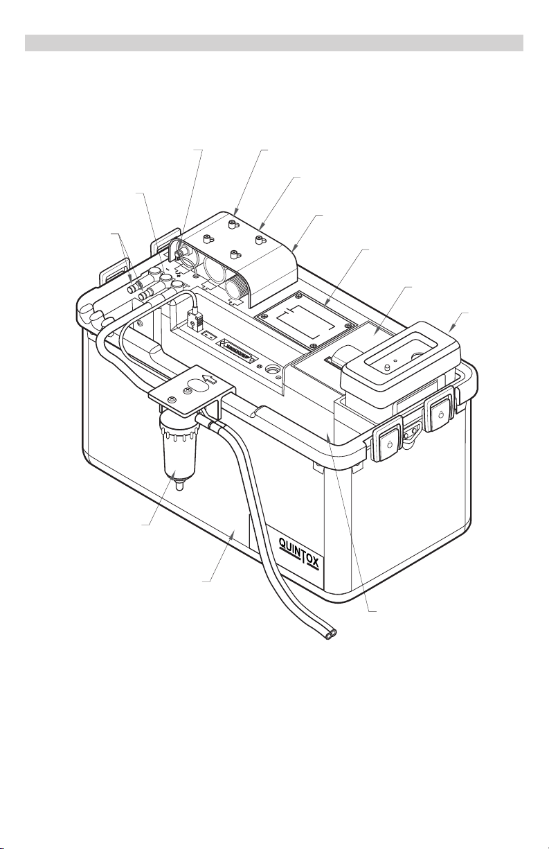
ANALYZER LAYOUT AND FEATURES
ANALYZER LAYOUT
FOR OXYGEN SENSOR
CONNECTION LEAD
FOR OXYGEN SENSOR
PRESSURE / DRAFT
PORTS
WATERTRAP
LOCATED ON SIDE
OF INSTRUMENT
CONNECTION LEAD
PRESSURE PRESSURE
OXYGEN SENSOR
FILTER BRIDGE OR
SULPHUR FILTER
PARTICLE FILTER
Kane
International
SF1
WATER
TRAP
AIR FILTER
AF2
BATTERY
ENCLOSURE
PRINTER UNIT
GAS ANALYSER
BATTERY ENCLOSURE
PRINTER UNIT
HANDSET
(STORED IN
POCKET)
INSTRUMENT CASE
ACCESSORY STORAGE SPACE
(LEADS, WATERTRAP ETC)
9
Page 10

ANALYZER LAYOUT WITH KMDM220 GAS CONDITIONING MODULE FITTED
PARTICLE FILTER
OXYGEN SENSOR
DUAL PRESSURE PORTS
FLUE SOCKET
OXYGEN SENSOR
CONNECTOR
PRINTER UNIT
Kane
International
SF1
WATER
TRAP
PRESSURE
PRESSURE
INLET SOCKET
BATTERY
ENCLOSURE
AF2
AIR FILTER
AUX CONNECTOR
(25 PIN ‘D’)
HEATED LINE
CONNECTION
GAS DRYER
ASSEMBLY
FLUE GAS ANALYSER
INSTRUMENT CASE
WATERTRAP CONNECTION
WATER
TRAP
PRESSUREPRESSURE
ANALYZER ‘ON’ SWITCH
REMOTE HANDSET
CONNECTION
(8 PIN DIN)
BATTERY
ENCLOSURE
CHARGER INPUT SOCKET
RED POWER LED
10
REMOTE HANDSET CONNECTION
(8 PIN DIN)
Page 11

TYPICAL PROBE CONFIGURATION (KMCP6)
THERMOCOUPLE CONNECTION (FLUE)
Kane
PRESSURE PRESSURE
International
SF1
WATER
TRAP
AIR FILTER
AF2
SOCKET FOR
OPTIONAL AIR INLET
TEMPERATURE PROBE
BATTERY
ENCLOSURE
PRINTER UNIT
DEPTH STOP CONE
PROBE HANDLE
11
GAS ANALYSER
WATERTRAP LOCATED
ON SPIGOT IN CASE
PROBE GAS CONNECTION
TO WATERTRAP
Page 12

ANALYZER CONNECTIONS
AUX CONNECTOR (25 PIN ‘D’)
INLET TEMPERATURE SOCKET
FLUE TEMPERATURE SOCKET
OXYGEN SENSOR
CONNECTOR
PRESSUREPRESSURE
DUAL PRESSURE
PORTS
ANALYSER ‘ON’ SWITCH
REMOTE HANDSET CONNECTION
(8 PIN DIN)
RED POWER LED
CHARGER INPUT SOCKET
BATTERY
ENCLOSURE
WATER
TRAP
PRINTER UNIT
HANDSET REMOTE CONNECTION
(8 PIN DIN)
GETTING STARTED
• Check that you have all the items you have ordered.
• Before attempting to use the analyzer to take readings it is recommended that the batteries be fully
charged.
• When the charger is connected to the analyzer and powered up the red LED by the charger socket
will flash until the batteries are fully charged. Once the batteries are fully charged the LED will no
longer be illuminated.
• To charge the handset; connect the handset to the main analyzer unit using its cable.
While switched off, but charging, the display will show the Kane logo and a battery charging icon
in the bottom right hand corner of the handset screen.
Note: The handset battery is charged via the external battery charger and not from the analyzer’s
internal battery. Once the handset battery is fully charged the icon will disappear from the screen.
The handset can also be charged directly using the main charger as used for the analyzer.
12
Page 13
BEFORE TAKING READINGS
You need to establish the current set up of the analyzer and then you can customize to suit your testing
needs.
Press the MENU key and then select STATUS as described below.
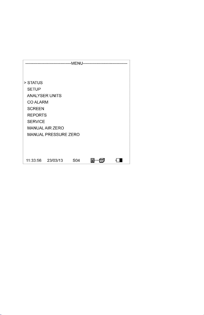
MENU: ALL THE OPTIONS
• Press the MENU key.
The > symbol acts as the cursor. It can be moved up or down by pressing the UP or DOWN keys.
Having made a selection press the ENTER key.
The bottom line of this screen lists:
• the time
• the date
• the number of satellites being received
• the Bluetooth connection status
• the estimated charge in the handset battery
13
Page 14

STATUS: ESTABLISHING THE ANALYZER’S SET-UP
Press MENU and then select STATUS by pressing ENTER.
This screen lists :
• the software version in the handset
• the handset serial number
• the analyzer unit software version number
• the analyzer unit serial number
• the estimated charge in the main battery
• the estimated charge in the heater battery (if fitted)
• the number of days before annual re-calibration is due
14
Page 15

Press DOWN to move to the next screen.
• Press DOWN to move to the next screen.
• Press DOWN to move back to the first screen.
• Press PRINT to print this status on the analyzer’s printer.
• Press MENU to EXIT.
15
Page 16

SETUP: CONFIGURING THE ANALYZER’S SETUP
LANGUAGE:
• Align cursor using UP or DOWN keys, then press ENTER.
• Use UP or DOWN keys to scroll through the selection.
• Press ENTER to select.
16
Page 17

MAIN PURGE:
• AUTO PURGE: Set YES or NO
• AUTO PURGE DURATION TIME: Set fresh air purge duration to between 2 and 30 minutes.
• MAIN PURGE INTERVAL TIME : Set the interval between fresh air purges to between 10 and 120
minutes.
• AUTO ZERO CAL: Set YES or NO to automatically re-zero sensors at the end of a
main purge cycle.
• AUTO PUMP FLOW: Set YES or NO to automatically control the pump flow. This may
be required for some regulatory test protocols.
After switch on, the first purge interval is automatically set to 10 minutes if the optional IR module is
fitted. Changes in the purge interval are implemented after completion of the next purge cycle. To
implement a change immediately perform a “MANUAL AIR ZERO”.
PRINTER:
This sets the destination for outputs from the handset.
The choices of outputs are:
• KMIRP
• IRP-2
• ANALYZER PRINTER
• SERIAL
• BLUETOOTH
Use UP or DOWN keys to scroll through the selection. Press ENTER to select,
17
Page 18

AUTO SET TIME:
This function is locked if reports have been stored. To allow the function to operate, delete the reports. This
allows the time to be set automatically from the GPS signals. Select NO to maintain manual setting.
Use UP or DOWN keys to scroll through the selection. Press ENTER to select,
SET TIME:
This function is locked off if “AUTO SET TIME” is activated or reports have been logged. If this function is
locked, delete the reports.
If manual setting is enabled use UP or DOWN keys to change values.
Press ENTER to select.
18
Page 19

SET DATE:
This function can only be set manually, not by GPS.
If this function is locked, delete the reports.
If manual setting is enabled use UP or DOWN keys to change values.
Press ENTER to select.
HEATER STATUS:
Switch off heaters or operate automatically.
Use UP or DOWN keys to scroll through the selection. Press ENTER to select.
SELECT ANALYZER UNIT SERIAL NUMBER:
If more than one analyzer unit is within Bluetooth range the handset needs to be set to communicate with
the correct unit.
Use UP or DOWN keys to scroll through the selection. Press ENTER to select.
BLUETOOTH SET UP:
The handset can communicate with an analyzer unit or a PC. Bluetooth can also be switched off and a cable
can be used.
Use UP or DOWN keys to scroll through the selection. Press ENTER to select.
BLUETOOTH PASSKEY:
This confirms the Passkey setting.
The Bluetooth Passkey is 1111.
19
Page 20

ANALYZER UNITS:
CONFIGURES ALL THE DATA SOURCES AND SETTINGS
FUEL ORIGIN:
Select from a list of country specific fuel tables.
•
Use UP or DOWN keys to scroll through the selection. Press ENTER to select,
•
FUEL TYPE:
Select from the list of fuel types associated with the chosen origin. The K values for the
•
selected fuel are also shown.
Use UP or DOWN keys to scroll through the selection. Press ENTER to select.
•
There are 5 User Fuels that can be loaded from a PC. The title of these user fuels can be edited
•
using the keypad on the handset.
Use UP or DOWN keys to scroll through the selection. Press ENTER to select.
•
EFFICIENCY:
Select NET or GROSS, condensing net, condensing gross efficiency calculation
•
Use UP or DOWN keys to scroll through the selection. Press ENTER to select.
•
GAS UNITS:
Select ppm or ppmn or mg/m3 or mg/m3n.
•
Use UP or DOWN keys to scroll through the selection. Press ENTER to select.
•
TEMPERATURE:
Allows the selection of Fahrenheit or Celsius.
•
Use UP or DOWN keys to scroll through the selection. Press ENTER to select.
•
20
Page 21

PRESSURE:
Allows the selection of pressure units.
•
Select from: mbar, In H2O, mm H2O, hPa, psi.
•
Use UP or DOWN keys to scroll through the selection. Press ENTER to select.
•
SET PERCENTAGE REFERENCE O2:
Can be set between 0% (equivalent to OFF) and 10%.
•
Use UP or DOWN keys to scroll through the selection. Press ENTER to select.
•
SET NOx CALCULATION:
• Select from: SUM, NO2 or NO
• Set REFERENCE NOx to the percentage required or defined by local regulations.
Typically 5% NO2 is added to an NO reading. The value can be user set.
• SUM adds the readings from an NO sensor and an NO2 sensor when fitted
• NO calculates an NOx reading from the NO reading where NOx = NO x 1.1
NO2 calculates an NOx reading from the NO2 reading where NOx = NO2 x 2.05
• Use UP or DOWN keys to scroll through the selection. Press ENTER to select.
CONVERSION FACTORS:
Display the Propane Equivalency Factor PEF and the Methane Equivalency Factor for the IR module
(if fitted) and the pitot factor – change from 0.10 to 1.00 as determined by the pitot tube being used.
CO ALARM:
21
Page 22

CO ALARM SET:
• Switch the alarm ON or OFF.
• Use UP or DOWN keys to scroll through the selection. Press ENTER to select.
CO ALARM LEVEL:
• Allows a specific CO level in ppm to be set as the alarm trigger point.
• Use UP or DOWN keys to change the digits. Press ENTER to select and move to the next digit.
• The display will show ‘++++’ when the CO alarm is triggered.
SCREEN:
The screen display is fully configurable.
CONTRAST:
• Allows the display to be darkened or lightened. Default value is 14.
• Use UP or DOWN keys to change the digits. Press ENTER to select and move to the next digit.
B’LIGHT:
• The switch off time for the backlight can be set for between 30 and 300 seconds,
• Use UP or DOWN keys to change the digits. Press ENTER to select and move to the next digit.
• During normal measurements press ENTER to switch the backlight on.
MODE:
• The main display can be set for SMALL font or LARGE font.
22
Page 23

LINES:
• This feature allows users to customize the screen display to suit their own requirements.
• Use UP or DOWN keys to change the selection. Press ENTER to select and move to the next digit.
• So for Lines 1-6, the screen shows:
• The parameter to be displayed on each line can be individually selected.
• Use UP or DOWN keys to change the selection. Press ENTER to select and move to the next digit.
REPORTS: CONFIGURES REPORTS
23
Page 24

VIEW REPORTS:
• This selection displays a ‘main screen’ with a LOG number near the top left hand of the display.
• This number can be changed using UP or DOWN and the display automatically changes.
DELETE ALL REPORTS:
• All reports can be deleted. A confirmation YES is required.
• Use UP or DOWN keys to scroll through the selection. Press ENTER to select,
AUTO LOG TIME:
• Automatic logging/printing can be selected for intervals between 10 seconds and 90 minutes.
• Use UP or DOWN keys to scroll through the selection. Press ENTER to select,
START AUTO LOG:
• Select YES or NO.
• Use UP or DOWN keys to scroll through the selection. Press ENTER to select,
START AUTO PRINTING:
• Select YES or NO.
• Use UP or DOWN keys to scroll through the selection. Press ENTER to select,
HEADER 1: 16 CHARACTERS
• Allows the printed header line: YOUR COMPANY to be changed.
• Use UP or DOWN keys to change the characters. Press ENTER to select and move to
the next character.
HEADER 2: 16 CHARACTERS
• Allows the printed header line: NAME & PHONE number to be changed.
• Use UP or DOWN keys to change the characters. Press ENTER to select and move to
the next character.
24
Page 25

FORM FEED:
• Allows remote paper feeding on printers.
RECERTIFICATION:
• CODE: For use by authorized service agents.
• CAL DATE = number of days before annual recertification is due.
MANUAL AIR ZERO:
• Select this and press ENTER to initiate a fresh air purge and sensor zeroing
MANUAL PRESSURE ZERO:
• Select this and press ENTER to re-zero the pressure sensor
BEFORE USING THE ANALYZER FOR THE FIRST TIME.
SAFETY WARNING
This analyzer extracts combustion gases that may be toxic in relatively low concentrations. These gases are
exhausted from the bottom of the instrument. This instrument must only be used in well-ventilated locations.
It must only be used by trained and competent persons after due consideration of all the potential hazards.
FIRST TIME USE
Charge the batteries for 12 hours; following this an overnight charge should be sufficient for an average
8-hour day. There may be three battery packs that need charging, the main battery, the optional heater battery and the handset battery. The handset battery can use the same charger as the analyzer unit or can be
charged via the main unit using a handset lead. All batteries are NiMh.
• While charging the red LED will flash.
• We offer a wide choice of probes, which are not supplied as standard and must be ordered as a
separate item.
• Take time to read this manual fully.
TIP: Take a look at the Spare Parts list and order some replacement filters and paper rolls now.
25
Page 26

NORMAL START UP SEQUENCE
EVERY TIME YOU USE THE ANALYZER
BEFORE SWITCH-ON CHECK THAT:
• the oxygen sensor is connected
• the particle filter is not dirty
• the sulphur filter is fitted for heavy oil or coal
• the water trap and probe line are empty of water
• all hose connections, etc, are properly made
• the paper roll is fitted
• the analyzer unit is in fresh air
• the water trap is vertical
• the flue temperature is connected
• the instrument is placed on a clean, flat, level surface
Switch ON the analyzer by pressing ON/OFF on the handset. You also need to press the ON/OFF
switch on the analyzer main unit.
AUTOMATIC CALIBRATION
• During this sequence the analyzer pumps fresh air into the sensors to allow toxic sensors to be set to
zero and the oxygen sensor to be set to 20.9 %.
• During this sequence the handset display will show the following:
Note: The software version number and serial number are examples only.
26
Page 27

If there is no Bluetooth communication between the handset and the main unit the
following will appear on the screen.
• Press ENTER to continue and follow the instructions.
• Once Bluetooth communication is established the main measurement screen will appear.
MAIN MEASUREMENT SCREEN
IN SMALL FONT MODE
27
Page 28

• TOP LINE: shows status messages
• GASES: O2 and CO2 are shown in % other gases shown in ppm or other user selected
units CO can be shown in % if optional IR bench is fitted
• TEMPERATURES: displayed in C or F. N\F = not fitted
---- occurs for calculations when N\F applies
---- occurs when a calculation cannot be made due to an out of range value (Eg zero)
• Atmospheric pressure (ATM) is always displayed in mbar.
IN LARGE FONT MODE
There are 5 screens that are accessed using the UP or DOWN keys
28
Page 29

29
Page 30

SAMPLING THE FLUE GAS
Once the automatic calibration procedure has been completed and the specific fuel has been selected the
probe can be inserted into the desired sampling point.
It is recommended that the sampling point be located at least two flue diameters downstream of any bend
and that the probe tip is in the center of the flue (this is normally the point of the hottest temperature).
With balanced flues and other industrial units the probe should be positioned far enough into the flue so
that no air can ‘back flush’ into the probe.
The probe depth stop cone provided with the instrument allows the probe to be used in holes whose
diameters range from 8 mm to 21 mm (5/16 to 4/5 inch).
The standard probe is rated at 650°C/1202°F. Temperatures of up to 100°C/2012°F can be accommodated
using an optional high temperature probe.
TIP: To conserve battery power, switch off the pump when you are not taking a measurement. Use the
pump key to turn the pump ON and OFF.
LONG TERM MONITORING
There are a number of things that need to be considered for successful long term
unattended monitoring:
• The provision of enough power for the duration of the test
• The capability to empty the water trap
• Regular fresh air purging of the sensors
• Protection from rain or water spray from the process being monitored.
If a mains power source is being used it is strongly recommended that the supply cable be protected by a suitable Residual Current Device (RCD).
Unless the water trap is to be regularly inspected then a pumped water trap should be fitted.
Electrochemical sensors need regular refreshing with fresh air, preferably at around 50% RH. They also
need a small percentage of oxygen to be present in the sampled gas. If there is zero oxygen the output
from the sensors will decay over time (10 minutes or so). In such circumstances, fresh air purge should be
programmed for a 50% duty cycle every 10 minutes.
The longest sampling time without purging should be limited to 2 hours and then purge for 30 minutes.
When the KHC infrared module is fitted, for maximum accuracy it is recommended that purging occur
every 30 minutes.
30
Page 31

KMDM220 GAS CONDITIONING MODULE
This module is fitted in the front compartment of a standard K9206 carry case and comprises a Peltier fan
cooled chiller assembly, a peristaltic pump to automatically remove condensate, the control electronics
and a power supply module. The module is supported on an aluminum alloy chassis.
The chiller is connected to a flue mounted electrically heated probe (KMHP1200) by a 9.8 foot long heated
line with automatic temperature control (KMHL3000). Because the gas that is extracted from the flue is
maintained at 248°F no condensation occurs in the probe or the hose and so no sample gas is lost in the
condensate. The chiller flash cools the sample gas to below the ambient dew point and any water in the
gas immediately condenses. The condensate is then pumped away using a peristaltic pump. Because the
gas has no chance to remain in contact with the condensate, volatile sample gas is not lost into the condensate. The chilled gas then naturally warms up as it passes through the sampling pump to the sensors
and as it does so its humidity reduces and there is no risk of further condensation.
SETTING UP KMDM220
The heated sample probe must be connected to the top of the heated line and a gas tight connection
be made without over tightening the connections. This joint must then be thermally insulated. Both the
heated probe and the heated line must be connected to a mains power source via a suitable Residual
Current Device (RCD) and be left powered up for 20 minutes to achieve their operating temperature before
attempting to extract sample gas.
When the probe is inserted into the sampling point is must be suitably supported to prevent bending and
unnecessary strain. Likewise the heated line should be carefully supported and never be twisted or kinked
as this may damage the internal heating elements.
The heated line is connected to the chiller by attaching the end of the line to the through bulkhead connection in the K9206 carry case. A short flexible connection then links the hose to the chiller. The chiller
needs to be powered up for at least 10 minutes before it is used.
The peristaltic pump operates automatically. Always check that the drain of the peristaltic pump is clear
and that there are no blockages. The peristaltic pump needs to have its flexible rotor replaced after every
1000 hours of operation.
To operate efficiently the chiller needs to be well ventilated so the case lid must be removed, however
the unit must be protected externally to prevent ingress of water from either the plant being tested or
from rainfall.
31
Page 32

MAINTENANCE
EMPTYING AND CLEANING THE IN-LINE WATER TRAP
The water trap should be checked and emptied on a regular basis. Water vapor will condense in the probe
line, which may cause the water trap to fill beyond the maximum level mark. If this occurs water could be
drawn into the analyzer causing damage. Care should be taken at all times to avoid this risk.
Emptying of the water trap is detailed below:
Carefully remove the end cap from the in-line housing. Dispose of the condensate in a suitable drain; care
must be taken, as it could be acidic. If condensate spills onto the skin or clothing, clean off immediately
using fresh water and seek medical advice if problems occur.
CHANGING THE PARTICLE FILTER
This is a very important part of the analyzer and should be changed regularly. It prevents dust and dirty
particles entering the pump and sensors and hence causing damage. The filter MUST be changed when it
appears discolored.
Remove the end cap from the filter housing. Carefully remove the paper filter element and dispose of it.
Clean the inside of the filter housing with a suitable soft cloth. Insert a new filter element onto the spigot
on the filter end cap and carefully insert it into the filter body.
32
Page 33

CHARGING THE BATTERY
It is important that the battery is charged on a regular basis. The instrument constantly powers the internal sensors and may discharge the battery if left unattended for serveral months. Connect the charger
supplied with the instrument to the correct mains supply.
Note: The correct charger type may be required for your local voltage i.e. 110 or 220volts AC.
Insert the plug in the socket marked CHARGER INPUT SOCKET
The CHARGER ON RED LED will flash showing the instrument is charging.
CHANGING THE PAPER ROLL
To change the paper roll, remove the printer cover by loosening the two screws holding it down. Remove
the old paper roll core and insert the new roll so that it sits as follows:
Feed the free end of paper into the printer through the metal slot beneath the printer ribbon. Start the
paper feed sequence until the paper has emerged from the top of the printer, feed the loose end through
the cover and refit.
TO START PAPER FEED
Go to MENU, REPORTS, FORM FEED
CHANGING THE PRINTER RIBBON
The printer ribbon cartridge will last for approximately two rolls of paper. Remove the printer cover as
detailed above.
Marked on one end of the cartridge is PUSH. Gently press down on this end and the ribbon cartridge will
pop up at the other end. Remove the cartridge and dispose of.
33
Page 34

Fit a new ribbon guiding the paper roll between the exposed ribbon and cartridge body.
PROBLEM SOLVING
The following is a list of problems that may occur on the instrument through its operating life. If the
cause of the fault is not easy to identify then we advise you to contact the Kane International Service
Department or an International Distributor for expert advice.
Fault symptom Causes
Oxygen too high
CO2 too low
Analyzer not holding charge
Analyzer not charging
Analyzer does not respond to flue gas Particle filter blocked.
Flue temperature readings erratic Temperature plug reversed in socket.
Analyzer automatically switches off in operation. Battery below alarm level.
Display is blank. The contrast setting has been lost and requires
Air leaking into probe, tubing, water trap,
connectors or internal to instrument.
Oxygen cell needs replacing.
Battery exhausted.
AC charger not giving correct output.
Fuse blown in charger plug.
Probe or tubing blocked.
Pump not working or damaged with contaminants.
Faulty connection or break in cable or plug.
Battery quickly discharging and is faulty.
resetting. Disconnect handset lead and reconnect.
Set contrast as in MENU : SCREEN : CONTRAST
34
Page 35

HOW TO GET EXPERT HELP
There will be occasions when despite having read the manual there will be problems that you cannot
resolve and so you need external help.
Before calling UEi Test Instruments please check the following first:
Find the serial number of the instrument. It is located on the label close to where the charger and handset
leads plug into the analyzer. Also make a note of which sensors are fitted by observing the tick marks on
the instrument label.
If the handset and analyzer are operating you can also determine the issue of software loaded in the
analyzer and its handset by viewing STATUS. If you can, take a printout of STATUS and a printout of the
measurement screen so that they can be faxed or emailed to your technical support advisor.
END OF LIFE DISPOSAL
The Waste Electrical or Electronic Equipment (WEEE) Directive requires countries in the EU to maximize
collection and environmentally responsible processing of these items.
Products are now labeled with a crossed out wheeled bin symbol to remind you that they can be recycled.
BATTERY DISPOSAL
All the user replaceable batteries used in this product are NiMh and are suitable for recycling through any
local waste portable battery recycling scheme.
ANNUAL RECERTIFICATION
Although sensor life is typically more than five years, the monitor should be re-calibrated and serviced
annually to help prevent any long-term sensor drift or accidental damage.
Local regulations may require more frequent re-calibration.
In the USA, UEi Test Instruments has recertification facilities at Beaverton, OR and Indianapolis, IN.
RETURNING YOUR ANALYZER TO UEi
When returning your K9206, contact customer service at 800-547-5740 or fill out our service request form
at www.ueitest.com.
Please always ensure that you enclose:
• Your full contact details
• A daytime telephone number
• Details of faults you might have experienced
• Any relevant accessories (eg. Probe, printer, adaptor and leak detectors). Any accessories that are
returned will be checked. If an accessory has failed then we will quote you for a repair or a
replacement.
35
Page 36

PACKING YOUR ANALYZER
When returning your analyzer, please pack it appropriately to prevent any damage during transit.
Before sealing your package, please ensure that you have enclosed the items listed above and that it is
clearly marked for the attention of:
WWW.UEITEST.COM
PORTLAND, OR
Headquarters
Recertification Center
1-800-547-5740
info@ueitest.com
SENDING YOUR ANALYZER
Once the analyzer has been securely packed then your package is ready for shipment back to UEi Test
Instruments. If you do not have an account with a courier company you can take your package to your
local Post Office. It is advisable to send the package by Special Delivery so that it is insured and traceable
while in transit.
WHEN WE RECEIVE YOUR ANALYZER
On receipt of your package, our Service Engineers will inspect the analyzer and any accessories and
confirm to you the total service cost. Once you have accepted this, the work will be carried out, and upon
completion the analyzer returned to you.
INDIANAPOLIS, IN
Recertification Center
1-800-547-5740
info@ueitest.com
VANCOUVER, BC
Recertification Center
ISO/IEC 17025:2005
NIST Certification
1-877-475-0648
infocanada@ueitest.com
If you have any questions that we haven’t answered, please contact UEi:
1-800-547-5740 • FAX: (503) 643-6322
www.ueitest.com • Email: info@ueitest.com
36
Page 37

PRODUCT SPECIFICATION
UNIT
Temp Measurement Resolution Accuracy Range
Flue Temperature 0.1° (C/F) 1.0°C ± 0.3% of reading 0 - 1100°C
32 - 2140°F
* Use high temperature probe
for gases >600°C/1112°F
Inlet Temperature 0.1° (C/F) 1.0°C ± 0.3% of reading 0 - 600°C
0 - 999°F
Gas Measurement
*1
Resolution Accuracy Range
Oxygen (02): 0.1% -0.1% +0.2% 02 0- 25%
Carbon monoxide (CO):
(standard: H compensated)
1ppm ± 5ppm < 100ppm
5% of reading < 2000ppm
0 - 10,000ppm
± 10% of reading >2000ppm
Nitric oxide (NO):
(high range)
Nitric oxide (NO):
(low range)
Nitrogen dioxide (NO2): 1ppm ± 5ppm < 100ppm
1ppm ± 5ppm < 100ppm
± 5% of reading > 100ppm
1ppm ± 2ppm < 30ppm
± 5ppm > 30ppm
0 - 5,000ppm
0 - 100ppm
0 - 1,000ppm
± 10ppm < 500ppm
± 5% of reading > 500ppm
Sulphur dioxide (SO2)
(low range):
Sulphur dioxide (SO2)
(high range):
Hydrogen sulphide: 1 ppm ± 5ppm < 100ppm
1ppm ± 2ppm < 30ppm
± 5ppm > 30ppm
1ppm ± 5ppm < 100ppm
± 5% of reading > 100ppm
0 - 100ppm
0 - 5,000ppm
0 - 1,000ppm
± 5% of reading > 100ppm
Pressure: 0.01mbar ± 0.5% Full scale 0 - 150mbar
Carbon dioxide (CO2)
Efficiency
*1
using dry test gases at STP
*2
calculated
*2
: 0.1% ± 1% 0 - 100%
*2
: 0.1% ± 0.3% CO2 0 - Fuel Value
NB: all ppm reading can be displayed in mg/m3 and can be normalized
37
Page 38

OPTIONAL IR MODULE
Hydrocarbons:
Range: Overrange Accuracy Resolution
0-5,000ppm 10,000ppm +5% of reading and + 12ppm vol. 1ppm
CO2:
Range: Overrange Accuracy Resolution
0-20% 40% +5% of reading and + 0.5% vol. 0.1%
CO:
Range: Overrange Accuracy Resolution
0-10% 20% +5% of reading and + 0.2% vol. <30% 0.1%
Response time T90: 30 seconds
Warm up time: 3 minutes
Operating temperature range: 5 to 50 deg. C.
Operating humidity: 10-80% non condensing
Power: Supplied by K9206
Conversion Factors from a Propane Calibration
Propane multiply by 1
Methane multiply by 0.1
Hexane multiply by 2
HANDSET
Dimensions 8.66” long (220mm long)
4.72” high (120mm high)
1.96” wide (50mm wide)
Keypad tactile keys
Display graphical with backlight and contrast control
EXTENSION CABLE
Specification: 8 pin DIN cable
Cable lengths: 16’ Standard 32’-65’-Optional
MAIN BATTERY AND OPTIONAL HEATER BATTERY
Type: NiMH Rechargeable (12V, 2AH)
Life: 8 hours from full charge
Charge time: 12 hours trickle 4 hours fast charge
38
Page 39

BATTERY CHARGER
Input: 100V-240V AC 60 watts
Output: 15V DC @ 4 amps
PUMP
Flow rate: 2 Liters/Minute nominal 500 mbar static suction
INTEGRAL PRINTER
• 16 character dot matrix.
• Plain paper
AMBIENT OPERATING RANGE
• -10°C to + 55°C
• < 85% RH non condensing
• Storage: -10°C to 55°C
HEATED LINE: KMHL3000
• Power supply: 220V ac @ maximum 300 watts
HEATED PROBE: KMHP1200
• Power supply: 220V ac @ maximum 100 watts
• 1200mm insertion length, 8 mm diameter rated to 1000 o C
GAS CONDITIONING MODULE: KMDM220
• Power supply: 220 Vac @ 5 amps peak.
PROBE
• Choose from a range of probe options. See probe website.
OPTIONAL PORTABLE PRINTERS
• Compatible with KMIRP and IRP-2
39
Page 40

APPENDICES
A – PARAMETER MEANINGS
The parameters and their meanings are detailed as follows : -
• DATE : Analyzer date.
• TIME : Analyzer time.
• MAIN BATTERY/ Displays the battery level from 0-100%. The analyzer will flash
HEATER BATTERY: RECHARGE BATTERY at less than 10 % of charge. The analyzer
may show levels greater than 100% when the charger is connected.
• ----- : Displayed when a calculation cannot be performed because a probe is not
fitted or a parameter is out of range.
• FUEL : The fuel used in calculation of efficiency and carbon dioxide.
• K1g: Gross calorific fuel constant. See Appendix for calculation.
• K1n : Gross calorific fuel constant. See Appendix for calculation.
• K2 : Percentage Maximum theoretical CO2 (dry basis).
• K3: Percentage wet loss.
• K4 : Percentage unburnt carbon loss.
• O2r : Toxic gas measurements can be referenced to defined oxygen levels.
Oxygen referencing is required by some regulations such as TALUFT. If a
reference value is selected the toxic gas measurements will be displayed with
the symbol n attached to the units. i.e. ppmn
What does oxygen reference mean?
If 3 % O2 reference is selected and 5 % O2 is measured in the flue then toxic
gas values will be recalculated as if 3 % were measured. The equation for
referencing is detailed in the Appendix. Oxygen referencing prevents false
readings being submitted, e.g. allowing more air into the boiler will increase
the oxygen level in the flue and hence dilute any toxic gas reading. Oxygen
referencing gives readings as if they were undiluted.
• NETT : Nett temperature calculated by deducting the internal AMBIENT temperature
from the measured FLUE temperature. Displays in either Centigrade C or
Fahrenheit F and will display NOT FITTED if flue probe not connected.
If an external INLET probe is used then INLET is deducted from FLUE.
• O2 : Oxygen reading in percentage %.
• CO : Carbon monoxide reading indicated in ppm or mg/m3. If the figures
are referenced to oxygen then the display will show ppmn or mg/m3n. Note
with a high CO sensor fitted the reading will be displayed in percentage %.
EFF (G) : Combustion Efficiency calculation displayed in percentage. Gross (G)
or Net (N) can be set. The calculation is determined by fuel type see
Appendix for calculation. The efficiency is displayed during a combustion test,
00.0 is displayed while in fresh air.
• CO2: Carbon dioxide reading in percentage % when measured, not calculated
• CO2c: Carbon dioxide calculation determined by the type of fuel. This only shows a
reading when a combustion test is being carried out. Zero (0.0) is displayed
while in fresh air.
40
Page 41

• FLUE : Temperature measured by flue gas probe in Centigrade or Fahrenheit. Will
show ambient temperature after fresh air calibration and N\F if probe
disconnected.
• INLET : Temperature measured by the optional inlet air probe or stored using the Flue
probe. The air probe is plugged into the instrument through the INLET socket.
This figure is used to calculate the NET temperature instead of AMBIENT
when fitted. Will show N\F if not fitted.
• AMBIENT : Temperature measured by the internal sensor, used in the NET temperature
• CO/CO2 R : The CO/CO2 ratio, is the ratio of measured CO divided by CO2.
It gives an indication of the following :- How good a gas sample the instrument
is reading. How clean the boiler is running. For example : A new or clean
domestic boiler will display a ratio of less than 0.004, a unit in need of cleaning
0.0040-0.0080 and a unit in need of major overhaul will show greater than
0.008. This only shows a reading when a combustion test is being carried out.
0.0000 is displayed while in fresh air.
• P INDEX : The CO/CO2 ratio expressed as a percentage %, called the ‘Poison Index”
i.e. P INDEX % = 100 x CO/CO2. 0.00 is displayed while in fresh air.
• XAIR % : Excess air calculated from the measured oxygen and type of fuel used.
Displays reading during a combustion test +++ is displayed while in fresh air.
• PRESSURE: Pressure reading. Units can be changed to different scales.
• NO: Nitric oxide reading in ppm or mg/m3. Displayed when nitric oxide sensor
fitted. Reading can also be referenced to oxygen ppmn or mg/m3n.
• NO2: Nitrogen dioxide reading in ppm or mg/m3. Displayed when nitrogen dioxide
sensor fitted. Reading can also be referenced to oxygen ppmn or mg/m3n.
• NOx : Calculated total nitric oxides displayed in ppm or mg/m3.
Reading can also be referenced to oxygen ppmn or mg/m3n.
• SO2 : Sulphur dioxide reading in ppm or mg/m3. Displayed when sulphur dioxide
sensor fitted. Reading can also be referenced to oxygen ppmn or mg/m3n.
• H2S: Hydrogen sulphide reading in ppm or mg/m3. Displayed when Hydrogen
sulphide fitted. Reading can also be referenced to oxygen ppmn or mg/m3n.
• HC : Unburnt Hydrocarbon reading in % of LEL of methane, the sensor is calibrated
with methane. Displayed when a Hydrocarbon sensor fitted.
LEL is the Lower Explosive Limit of a gas when mixed with air, for methane
this has the ratio of 19:1 Air:methane. Below the LEL the mixture can not
ignite and burn. In the Flue an unburnt Hydrocarbons should be well below
this level or there is the potential for an explosion.
• LOSS : Total losses calculated from Combustion Theory. This is the summation of the
next three parameters.
• DRY : Calculated heat lost in turning the carbon in the fuel to carbon dioxide (CO2).
• WET : Calculated heat lost in turning the hydrogen in the fuel into water (H2O).
• CO LOSS % : Calculated loss due to partially burnt carbon. Any carbon monoxide (CO) in the
flue has the potential to be turned into carbon dioxide and release more heat,
hence this heat is lost up the flue.
• GPS (Y): Latitude DDMM.MMM 5148.1060
• GPS (X): Longitude DDDMM.MMM -00011.450
• ATM: Atmospheric pressure in mbar
41
Page 42

B. NOx CALCULATIONS
ONLY AN NO SENSOR FITTED
• WORKING IN PPM: NOx REFERENCED TO NO
The user can select the assumed NO2 percentage and the O2 normalized level then: NOx in ppm = NO in
ppm multiplied by (1 + assumed NO2 percentage) in this setup NOx can only be displayed as NOx = NO
then normalizing:
NO in ppmn = NO in ppm multiplied by (21 minus the O2 norm setting) and then divided by (21 minus the
actual O2 reading)
For a worked example assume:
NO is 1000ppm
NO2 is 5% of NO
O2norm is set to 3%
actual O2 is zero
NOx in ppm = 1000 x (1 +5/100) =1000 x1.05 = 1050 ppm
NO ppmn = 1000 x (21 - 3)/(21-0) = 1000 x 18 / 21 = 857 ppmn
NOx ppmn = 1050 x 18 / 21 = 900 ppmn
or
NOx ppmn = 857 x 1.05 = 900 ppmn
• WORKING IN MG/M3: NOx REFERENCED TO NO OR NO2
The user can select the assumed NO2 percentage, the O2 reference level and whether the NOx reading is
referenced to NO or NO2
• WORKING IN MG/M3: REFERENCED TO NO
NO in mg/m3 = NO in ppm multiplied by 1.34
NOx in mg/m3 = NO in mg/m3 multiplied by (1 + assumed NO2 percentage)
• WORKING IN MG/M3: NOx REFERENCED TO NO2
NOx in mg/m3 = NO in ppm multiplied by 2.05 multiplied by (1 + assumed NO2 percentage)
or
NOx in mg/m3 = NO in mg/m3 divided by 1.34, multiplied by 2.05 and multiplied by (1 +assumed NO2
percentage)
• NORMALIZING READINGS
normalized reading = initial reading multiplied by (21 minus the O2norm setting) and then divided by (21
minus the actual O2 reading)
42
Page 43

BOTH NO AND NO2 SENSORS FITTED
• WORKING IN PPM: NOx = NO + NO2
normalizing readings
ppmn = initial reading in ppm multiplied by (21 minus the O2 norm setting) and then divided by (21 minus
the actual O2 reading)
• WORKING IN MG/M3
The user can select how the readings are referenced.
NOx = SUM
NOx = NO
NOx = NO2
• NOx = SUM
NOx in mg/m3 = NO in ppm multiplied by 1.34 plus NO2 in ppm multiplied by 2.05
• NOx = NO
NOx in mg/m3 = (NO in ppm plus NO2 in ppm) multiplied by 1.34
• NOx = NO2
NOx in mg/m3 = (NO in ppm plus NO2 in ppm) multiplied by 2.05
• NORMALIZING READINGS
ppmn = initial reading in ppm multiplied by (21 minus the O2norm setting) and then divided by (21 minus
the actual O2 reading)
mg/m3n = initial reading in mg/m3 multiplied by (21 minus the O2norm setting) and then divided by (21
minus the actual O2 reading)
ONLY AN NO2 SENSOR FITTED
When there is only an NO2 sensor fitted the NOx function is disabled
NO2 in mg/m3 = NO2 in ppm multiplied by 2.05
• NORMALIZING READINGS
ppmn = initial reading in ppm multiplied by (21 minus the O2norm setting) and then divided by (21 minus
the actual O2 reading)
mg/m3n = initial reading in mg/m3 multiplied by (21 minus the O2norm setting) and then divided by (21
minus the actual O2 reading)
43
Page 44

HIGH CO PURGE OPERATION
If there is a requirement to measure CO to concentrations above 10,000ppm then a High Purge module
should be fitted (this comprises both a purge pump and a solenoid) in addition to the IR triple gas bench.
When the electrochemical sensor’s reading passes 9800ppm the solenoid operates and the high purge
pump switches on and pumps fresh air across the electrochemical CO sensor. The displayed reading
changes at this point from ppm to % as measured by the IR module.
When the reading from the IR module falls below 0.95% the solenoid is deactivated and the high purge
pump stopped. After a short time the displayed reading will revert to ppm. There may be a small perturbation in readings at the point of changeover.
C. COMBUSTION EFFICIENCY CALCULATION
The efficiency calculation is based upon British Standard BS845.
This identifies three sources of loss associated with fuel burning:
• LOSSES DUE TO FLUE GASSES: Dry Flue gas loss,
Moisture and hydrogen
Sensible heat of water vapor
Unburned gas
• LOSSES DUE TO REFUSE: Combustible in ash
Combustible in riddlings
Combustible in dust
• OTHER LOSSES: Radiation
Convection
Conduction
Other unmeasured losses
Net efficiency calculations assume that the energy contained in the water vapor (formed as a product of
combustion and from wet fuel) is recovered and the wet loss term is zero. Gross efficiency calculations
assume that the energy contained in the water vapor is not recovered.
Since the fuel air mixture is never consistent there is the possibility of unburned/partially unburned fuel
passing through the flue. This is represented by the unburned carbon loss.
Losses due to combustible matter in ashes, riddlings, dust and grit, radiation, convection and conduction
are not included.
44
Page 45

EFFICIENCY CALCULATION:
• KNOWN DATA Fuel: Qgr = Gross Calorific Value (kJ/kg)
Qnet = Net Calorific Value (kJ/kg)
K1 = Constant based on Gross or Net Calorific Value:
K1g = ( 255 x %carbon in fuel )/Qgr
K1n = ( 255 x %carbon in fuel )/Qnet
K2 = % max theoretical CO2 (dry basis)
K3 = % Wet Loss
• MEASURED DATA: Tf = Flue Temperature
Ti = Inlet Temperature
O2m = % Oxygen in flue gas
• CALCULATED DATA: Tnet = Net Temperature
% CO2 content in flue gas
% Dry Flue Gas losses
% Wet losses
% Unburned carbon loss
% Efficiency
%CO2 = (20.9 - %O2m) x K2 / 20.9
Tnet = Flue Temperature - Inlet Temperature
Dry flue gas loss = 20.9 x K1n x (Tnet) / K2 x (20.9 - %O2m)
Wet loss = 9 x %H2 + %H2O / Qgr x [2488 + 2.1Tf - 4.2 Ti]
Simplified = [(9 x %H2 + %H2O) / Qgr] x 2425 x [1 + 0.001 Tnet]
Wet loss = K3(1+0.001xTnet)
Where K3 = [(9 x %H2 + %H2O) / Qgr] x 2425
Net Efficiency = 100% - dry flue gas losses
= 100% - 20.9 x K1n x (Tnet) / K2 x (20.9 - % O2m)
Gross Efficiency = 100% - {dry flue gas losses + wet losses}
= 100% - [20.9 x K1g x (Tnet) / K2 x (20.9 - %O2m)] + [K3 x (1 + 0.001 x Tnett)]
Excess Air = [(20.9% / (20.9% - 02m%)) – 1] x 100%
CO2% = [(20.9% - O2m%) x K2% / 20.9%]
Unburned fuel Loss = K4 x CO% / ( CO% + CO2% )
Where K4 = 70 for coke
= 65 for anthracite
= 63 for Bituminous coal
= 62 for coal tar fuel
= 48 for liquid petroleum fuel
= 32 for natural gas
The formula for K4 is based on the gross calorific value Qgr. To obtain the loss based on net calorific
value multiply by Qgr/Qnet. Since this loss is usually small this conversion has been ignored.
45
Page 46

OXYGEN REFERENCE
CO(n) = CO x (20.9 - O2r)
(20.9 - O2m)
D. CALCULATION OF FUEL DATA
For any fuel not specified by Kane International the net calorific value, gross calorific value and composition should be obtained from the fuel supplier.
The following fuel data has been calculated with reference to the efficiency calculation.
Example 1:
Chemical composition: C 25%
H2 3%
H2O 50%
Qnet 8.35 MJ/kg
Qg 9.3 MJ/kg *
Max CO2 20.4%
K1n = (255 x % carbon in fuel) / Qnet (kJ/Kg)
= (255 x 25) / 8350 = 0.763
K1g = (255 x % carbon in fuel) / Qg (kJ/Kg)
= (255 x 25) / 9300 = 0.685
K2 = Max % CO2 = 20.40
K3 = Wet Loss = [(9 x %H2 + %H2O) / 9300] x 2425
= [(9 x 3 + 50) / 9300] x 2425
= (77 / 9300) x 2425 = 20.08
K4 = 65 (an approximation for wood) *
The fuel values to program into the Analyzer are as follows:
NATURAL GAS
K1g : 0.763 K1n : 0.685
K_2 : 20.4 K_3 : 20.08
K_4 : 65 O2r : 8.0
* Assumed values in the absence of supplied data. See previous appendix for other fuels.
46
Page 47

E. ELECTROMAGNETIC COMPATIBILITY (CE) STATEMENT
This product has been tested for compliance with the following
generic standards:
EN 61000-6-3 : 2011
EN 61000-6-1 : 2007
and is certified to be compliant.
Specification
EC/EMC/KI/K9206 details the specific test configuration, performance and conditions of use.
SAFETY STANDARD
This product complies with the EN61010 Safety Standard (Safety requirements for
electrical equipment for measurement, control and laboratory use):
EN61010-1 : 2010
Protection Class 3 (SELV)
47
Page 48

K9206
Quintox Flue Gas Analyzer
Limited Warranty
The K9206 is warranted to be free from defects in materials and workmanship for a period
of one year from the date of purchase. If within the warranty period your instrument should
become inoperative from such defects, the unit will be repaired or replaced at UEi’s option.
This warranty covers normal use and does not cover damage which occurs in shipment or
failure which results from alteration, tampering, accident, misuse, abuse, neglect or improper
maintenance. Batteries and consequential damage resulting from failed batteries are not covered by warranty. Annual calibration is not covered as a warranty item.
Any implied warranties, including but not limited to implied warranties of merchantability and
fitness for a particular purpose, are limited to the express warranty. UEi shall not be liable
for loss of use of the instrument or other incidental or consequential damages, expenses, or
economic loss, or for any claim or claims for such damage, expenses or economic loss. A purchase receipt or other proof of original purchase date will be required before warranty repairs
will be rendered. Instruments out of warranty will be repaired (when repairable) for a service
charge.
For more information on warranty and service:
1-800-547-5740 • FAX: (503) 643-6322
www.ueitest.com • Email: info@ueitest.com
This warranty gives you specific legal rights. You may also have other rights which vary from
state to state.
Para la versión en español de este manual por favor visite www.ueitest.com
Pour une version française du manuel de l'utilisateur s'il vous plaît visitez www.ueitest.com
PLEASE
RECYCLE
Copyright © 2015 UEi. All Rights Reserved
17136 04/15
 Loading...