

Page 1

IRT803
OFF
1000V
500V
250V
100 V
V
ZERO
600V AC/DC Digital Insulation
Resistance Tester
INSTRUCTION MANUAL
ENGLISH
O
N
I
T
T
A
L
U
S
N
I
0 0.1 M 1 M 10 M 100 M 1 G 20 G
Apo
SELECT
PI/DAR
COMPARE
TEST
1000V
COM
OFF
ZERO
V
ZERO
Ω
E
S
T
E
R
IRT803
V
LOCK
HOLD
500V
250V
100 V
V
INSULATION
DC
600V
CAT IV 600V
CAT III 1000V
FUSED
1-800-547-5740
www.ueitest.com email: info@ueitest.com
Page 2

TABLE OF CONTENTS
FEATURES
GENERAL SPECIFICATIONS
IMPORTANT SAFETY WARNINGS
SYMBOLS
CATEGORY DEFINITIONS
OVERVIEW
OPERATING INSTRUCTIONS
Voltage <600V AC/DC .................................................................................................................7
Earth-Bond Resistance <20kΩ ..................................................................................................... 8
Continuity .................................................................................................................................... 9
Insulation Resistance/1000V/ 500V/ 250V/ 100V .................................................................... 10
Polarization Index & Dielectric Absorption Ratio (1000V, 500V, 250V, 100V) ........................... 11
Compare Function ..................................................................................................................... 12
Test Lead Notes ........................................................................................................................12
Testing the Fuse ........................................................................................................................13
Testing the Batteries .................................................................................................................13
Battery Replacement .................................................................................................................14
Fuse Replacement ..................................................................................................................... 14
Remote Probe Set ..................................................................................................................... 15
FCC/IC INFORMATION ................................................................................................................ 16
DISPOSAL ...................................................................................................................................16
CLEANING
STORAGE
WARRANTY
..................................................................................................................................................3
...................................................................................................................3
.......................................................................................................4
..................................................................................................................................................5
.......................................................................................................................5
.......................................................................................................................................... 6 - 7
................................................................................................................................... 16
................................................................................................................................... 16
................................................................................................................................. 16
2
Page 3

IRT803 Insulation resistance tester is designed to help prevent hazards such as electric shock and short-circuits
caused when the insulation in electrical devices, parts, and equipment used in plants, buildings, and other settings
degrades over long periods of use.
FEATURES
• Insulation Resistance 20.0GΩ
• 600V AC/DC
• Earth-bond Resistance 20.00kΩ
• Continuity
• PI/ DAR test
• Hold
• Test lead holders in boot
• Zero reading
• Lock reading
• Compare reading
• Rotary dial selector
• Protective rubber boot
• Kick stand
• Remote probe
• Auto power off
• Backlit Display
• Worklight
GENERAL SPECIFICATIONS
• Operating Temperature: 32˚ to 122˚F (0˚ to 50˚ C)
• Storage Temperature: 14˚ to 122˚F (-10˚ to 50˚C)
• Operating Humidity: <75%
• Operating Altitude: 6,562 ft (2000m)
• Pollution Degree: 2
• Backlight: Yes
• Refresh Rate: 3/sec
• Over-range: “OFL” is displayed.
• Dimensions: 8.27” x 3.52” x 2.17”
• Item Weight: 1.283 lbs.
• Calibration: Recommended annually
• CAT Rating: CATIV 600V/CATIII 1000V
• Certifications: cETLus 3rd edition, CE Conformity, CATIV 600V, CATIII 1000V, IP42, RoHS,
6’ Drop Protection, IEC/EN 61010-1: 2010
• Battery Type: (AA) 4
• Test Leads: Silicone test leads w/ alligator clips (red and black) (ATL57), Remote Probe
• Accuracy Temperature: 64˚ to 82˚F (18˚ to 28˚C)
• Temperature Coefficient: Nominal 0.1 x (Specified accuracy)/˚C
• Bargraph: 30 segments
3
Page 4

IMPORTANT SAFETY WARNINGS
WARNING
Read entire Safety Notes section regarding potential hazard and proper instructions before using this meter. In this manual
the word “WARNING” is used to indicate conditions or actions that may pose physical hazards to the user. The word
“CAUTION” is used to indicate conditions or actions that may damage this instrument.
WARNING
To ensure safe operation and service of the tester, follow these instructions. Failure to observe these warnings can result in
severe injury or death.
WARNING
• Before each use, verify meter operation by measuring a known voltage.
• Never use the meter on a circuit with voltages that exceed the category based rating of this meter.
• Do not use this meter during electrical storms or in wet weather.
• Do not use the meter or test leads if they appear damaged.
• Ensure meter leads are fully seated and keep fingers away from the metal probe contact when making measurements.
Always grip the leads behind the finger guards molded into the probe.
• Do not open the meter to replace batteries while the probes are connected.
• To avoid false readings that can lead to electrical shock, replace batteries if a low battery indicator appears.
• Unless measuring voltage, shut off and lockout power before measuring resistance.
• Always adhere to national and local safety codes. Use proper personal protective equipment (PPE) to prevent shock and
arc blast injury where hazardous live conductors are exposed.
• Always turn off power to a circuit or assembly under test before cutting, unsoldering or breaking the current path. Even
small amounts of current can be dangerous.
• Always disconnect the live test lead before disconnecting the common test lead from the circuit.
• In the event of electrical shock, ALWAYS bring the victim to the emergency room for evaluation, regardless of victim’s
apparent recovery. Electrical shock can cause unstable heart rhythms that may need medical attention.
• If any of the following occur during testing, turn off the power source to the circuit being tested: arching, flame, smoke,
extreme heat, smell of burning materials or discoloration or melting of components.
WARNING
Higher voltages require greater awareness of physical safety hazards. Before connecting the test leads; turn off power to
the circuit under test, set meter to the desired function and range; connect the test leads to the meter first, then connect to
the circuit under test. Reapply power. If an erroneous reading is observed, disconnect power immediately and recheck all
settings and connections.
WARNING
This meter is designed for trade professionals who are familiar with the hazards of their trade. Observe all recommended
safety procedures that include proper lockout utilization and use of personal protective equipment that includes safety
glasses, gloves and flame resistant clothing.
4
Page 5

SYMBOLS
COMPARE
RUN TIME
G
DC (Direct current) AC (Alternating Current)
Auto Power Off Active Negative DC
Low Battery High Voltage
Voltage Continuity
Ohms/Resistance
Warning or Caution Pass
Fuse Test
Kilo
Mega Hold
Giga Lock
PI/DAR Greater Than
ZERO
Ground 30 Segment Bargraph
Compare
Run Time
CATEGORY DEFINITIONS
Measurement
Category
II < 10 Circuits connected to mains socket outlets and similar points in the
III < 50 Mains distributions parts of the building
IV > 50 Source of the mains installation in the building
Short-Circuit (typical)
kA
a
Location in the
building installation
MAINS installation
5
Page 6

OVERVIEW AND OPERATING INSTRUCTIONS
A
O
N
I
T
T
A
E
L
U
S
N
I
B
S
T
E
IRT803
R
M
N
COMPARE
500V
HOLD
250V
LOCK
100V
V
J
K
L
O
P
Q
C
Apo
D
SELECT
E
F
G
PI/DAR
TEST
1000V
ZERO
V
OFF
H
COM
INSULATION
CAT IV 600V
CAT III 1000V
V
I
ZERO
Ω
FUSED
600V
A. Worklight: Lights work area in dark environments.
B. Display: High contrast and backlit.
C. Apo: Auto power off after 10 minutes of use
D. Select Button:
• Press to start battery test in AC/DC V mode.
• Press to activate Zero mode in Earth-bond resistance testing.
E. PI/DAR (Polarization Index/Dielectric Absorption Ratio) Button: Use PI for test of insulation deterioration and DAR for
extended insulation resistance test.
• Press x1 for PI mode.
• Press x2 for DAR mode.
F. Back light/ Worklight Button: Press to turn on worklight and back light.
G. Test Button: Start and stop measurement insulation, earth-bond resistance test and PI/PAR test. Also, used for testing the fuse.
H. Function Dial: Turns on meter and is used to select the function.
I. Category Max Indicator: Maximum CAT Rating for input jacks.
• Use CATIII test leads or higher
• Zero/Ω Test Lead Port: Fused, used for Zero Ohms.
• Common Test Lead Port:
• Volt/Insulation Test Lead Port: CATIV 600V/CATII 1000V, used for Volts, Continuity and Insulation test
J. Compare Button: Used to set a pass/fail compare level for insulation measurements.
K. Lock Button: Locks insulation or earth-bond resistance test to ON position. When pressed before the TEST button, the test
remains active until you press the lock or test button again to release the lock.
L. Hold Button:
• Press x1 for Hold mode.
M. Protective Rubber Boot: With molded comfortable grip.
6
Page 7
N. Test Lead Holders: Used for hands-free testing or storage
O. Kick Stand: For easy viewing of screen when testing.
P. Battery and Fuse Cover: (under protective rubber boot)
Q. Serial Number (under kick stand)
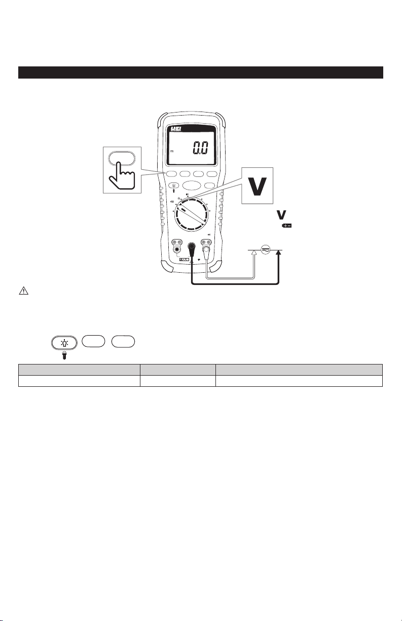
Voltage <600V AC/DC
If the meter detects higher than AC or DC 1.5V, the meter will automatically choose AC or DC.
O
N
I
T
T
A
E
L
S
U
T
S
E
R
N
I
IRT803
SELECT
SELECT
OFF
Apo
PI/DAR
ZERO
V
ZERO
Ω
FUSED
V
COMPARE
LOCK
HOLD
TEST
1000V
500V
250V
100V
V
INSULATION
COM
CAT IV 600V
CAT III 1000V
600V
WARNING
• Use CATIII rated Test leads or higher.
• Do not attempt to measure more than 1000V AC/DC.
• Keep hands below finger guards when measuring high voltage levels.
Features:
SELECT
HOLD
RANGE RESOLUTION ACCURACY
600V 0.1V ±(2% +3 dgts)
1. Bandwidth 45HZ to 400Hz
2. Input Impedance: 10MΩ (nominal), < 100pF
3. Overload Protection: AC 1000V rms or DC.
• Default =
• Press x1 =
7
Page 8

Earth-Bond Resistance <20kΩ
O
N
I
T
T
A
E
L
S
U
T
S
E
R
N
I
IRT803
IRT 803
TEST
COMPARE
1000V
V
LOCK
HOLD
500V
250V
100V
SELECT
TEST
SELECT
Apo
Apo
PI/DAR
ZERO
V
OFF
• Default =
ZERO
V
Ω
INSULATION
COM
CAT IV 600V
FUSED
CAT III 1000V
600V
• Press x1 =
• Short the ends of the test leads together, press the SELECT button and wait until ZERO appears. The meter measures the
test leads resistance, stores the data/results in memory and subtracts it from the reading. The test lead resistance is saved
even after the meter is powered off. If the Probe resistance is >2Ω, the resistance will not be saved.
• Connect the test leads to the circuit to be tested. The tester will automatically detect if the circuit is energized.
• The display will show “----” until a valid resistance reading is detected.
• The High Voltage symbol will display if greater than 2V AC or DC is present. If the meter “chirps”when you press the
TEST button, test is corrupted due to voltage being present.
• Press and hold the TEST button on the Meter or Remote Probe to start test. Test stops when the button is released.
Features:
TEST
SELECT
LOCK
NOTE: When the resistance is higher than the maximum display range the tester displays the > symbol and the maximum
resistance for the range.
WARNING
NEVER test resistance on a live circuit. (Overload Protection: AC 2V rms or DC)
RANGE RESOLUTION ACCURACY
20.00Ω 0.01Ω
200.0Ω 0.1Ω
2000Ω 1Ω
±(1.5% +3)
20.00kΩ 0.01kΩ
1. Accuracies apply from 0 to 100% of range
2. Open Circuit Test Voltage: > 4.0V, < 8V
3. Short Circuit Current: > 200.0 mA
8
Page 9

Continuity
HOLD
O
N
I
T
T
A
E
L
S
U
T
S
N
I
IRT803
IRT803
E
R
TEST
1000V
COMPARE
V
LOCK
HOLD
500V
250V
100V
SELECT
OFF
Apo
Apo
PI/DAR
ZERO
V
• Default =
ZERO
V
Ω
INSULATION
COM
CAT IV 600V
FUSED
CAT III 1000V
600V
Features:
WARNING
• Do not measure resistance/continuity on a live circuit.
• Beeper sounds constant as long as circuit is complete.
• Beeper sounds when a short (<40Ω) is detected.
RANGE RESOLUTION AUDIBLE THRESHOLD
400.0Ω 0.1Ω Approx. 40Ω
9
Page 10

OFF
Insulation Resistance/1000V/ 500V/ 250V/ 100V
O
N
I
T
T
A
E
L
S
U
T
S
E
R
N
COMPARE
I
0 0.1 M 1 M 10 M 100 M 1 G 20 G
Apo
Apo
SELECT
PI/DAR
TEST
ZERO
V
OFF
ZERO
Ω
COM
FUSED
600V
TEST
COMPARE
1000V
CAT IV 600V
CAT III 1000V
IRT803
IRT803
500V
INSULATION
V
M
V
DC
LOCK
HOLD
250V
100V
V
TEST
• Default =
1000V
ZERO
500V
V
OFF
ZERO
V
OFF
ZERO
V
250V
100V
1000V
500V
250V
100V
1000V
500V
250V
100V
• Set Rotary dial to a desired voltage position.
• The display will show “----” until a valid resistance reading is obtained.
• The High Voltage symbol will display if greater than 30V AC or DC is present.
• Press and hold the TEST button on the Meter or Remote Probe to start the test. Test stops when TEST button is released.
• Keep test leads on test points after TEST button is released. The circuit under test will then discharge.
Features:
LOCK
PI/DAR
Note: When the resistance is higher than the maximum display range the tester displays the > symbol and the maximum
resistance for the range.
WARNING
Do not measure resistance on a live circuit.
OUTPUT VOLTAGE DISPLAY RANGE RESOLUTION TEST CURRENT ACCURACY
100V (0% to +20%)
250V (0% to +20%)
0.01 to 20.00MΩ 0.01MΩ
20.0 to 100.0MΩ 0.1MΩ
0.01 to 20.00MΩ 0.01MΩ
20.0 to 200.0MΩ 0.1MΩ
1mA @ 100kΩ ±(3% +5dgts)
1mA @ 250kΩ ±(1.5% +5dgts)
0.01 to 20.00MΩ 0.01MΩ
500V (0% to +20%)
1mA @ 500kΩ ±(1.5% +5dgts)20.0 to 200.0MΩ 0.1MΩ
200 to 500MΩ 1MΩ
1000V (0% to +20%)
0.1 to 20.0MΩ 0.1MΩ
20 to 2000MΩ 1MΩ
1mA @ 1MΩ
±(1.5% +5dgts)
2.0 to 20.0GΩ 0.1GΩ ±(10% + 3dgts)
1. Measurement Range: 0.01MΩ to 20GΩ
2. Test Voltages: 100, 250, 500, 1000V
3. Test Voltage Accuracy: 0 to +20%
4. Short-Circuit Test Current: 1mA nominal
5. Auto Discharge: Discharge time <0.5 sec. for C = 1µF or less
6. Live Circuit Detection: Inhibit test if terminal voltage >30V prior to initialization of test
7. Maximum Capacitive Load: Operable with up to 1µF load
10
Page 11

Polarization Index & Dielectric Absorption Ratios (1000V, 500V, 250V, 100V)
O
N
I
T
T
A
E
L
S
U
T
S
E
R
N
1000V
ZERO
500V
V
OFF
ZERO
V
OFF
ZERO
V
OFF
250V
100V
1000V
500V
250V
100V
1000V
500V
250V
100V
Polarization Index (PI) is the ratio of the 10-minute insulation resistance to the 1-minute insulation resistance. Dielectric
Absorption Ratio (DAR) is the ratio of the 1-minute insulation resistance to the 30-second insulation resistance.
I
0 0.1 M 1 M 10 M 100 M 1 G 20 G
Apo
SELECT
PI/DAR
TEST
1000V
ZERO
V
OFF
ZERO
Ω
COM
FUSED
600V
IRT803
RUN TIME :
COMPARE
CAT IV 600V
CAT III 1000V
IRT803
500V
INSULATION
PI/DAR
V
G
V
DC
m s
LOCK
HOLD
250V
100V
V
• Press X1 =
• Press X2 =
TEST
• Default =
Features:
LOCK
PI/DAR
TEST
• Because of the time required for the PI and DAR tests, alligator clips are recommended.
• Use rotary selector dial to select desired test voltage.
• The display will show “----” until test starts.
• The High Voltage symbol will display if greater than 30V AC or DC is present.
• Press and hold the Test Button on the Meter or Remote Probe to start the test.
Note: When the resistance is higher than the maximum display range the tester displays the > symbol and the maximum
resistance for the range.
WARNING
NEVER measure resistance on a live circuit.
11
Page 12

Compare Function
4mm
Use the Compare Function to set “Pass/Fail” compare levels for insulation measurements.
Press the Compare Button to select the desired compare value. Choose from the following values:
• 100kΩ
• 200kΩ
• 500kΩ
• 1MΩ
• 2MΩ
• 5MΩ
• 10MΩ
• 20MΩ
• 50MΩ
• 100MΩ
• 200MΩ
• 500MΩ
Perform Insulation tests as described in this manual. The PASS symbol will appear on display if the measured value is greater
than the selected value.
Press and hold the Compare button to stop/disable the Compare function.
Test Lead Notes
CATIV 600V Measurement Locations
4mm
• Ensure the test lead shield is pressed firmly in place. Failure to use the CAT IV shield increases arc-flash risk.
CAT II Measurement Locations
18mm
• CAT IV shields may be removed for CAT II locations. This will allow testing on recessed conductors such as standard
wall outlets. Take care not to lose the shields.
WARNING: Test Lead category protections apply only to test leads and should not be confused with the meter’s specific
CAT rating. Observe the maximum category protection indicated on the meter the test leads are plugged into.
12
Page 13

Testing the Fuse
Apo
V
Apo
V
O
N
I
T
T
A
E
L
S
U
T
S
E
N
I
R
IRT803
600V
TEST
COM
COMPARE
1000V
CAT IV 600V
CAT III 1000V
500V
INSULATION
V
TEST
LOCK
HOLD
250V
100V
V
WARNING:
Apo
SELECT
PI/DAR
ZERO
V
OFF
ZERO
Ω
FUSED
To avoid electrical shock or injury, remove the test leads and any input signals/voltages before replacing the fuse.
• Turn the rotary selector dial to (ZERO/Ω) position.
• Press and hold the Test Button. If the display shows “FUSE” the fuse is bad and should be replaced. Please see Fuse
Replacement section of this manual.
Testing the Batteries
The meter continuously monitors battery voltage. If the Low Battery indicator is displayed, replace the batteries.
To manually test the batteries:
O
N
I
T
T
A
E
L
S
U
T
S
E
R
N
I
IRT803
SELECT
OFF
Apo
PI/DAR
ZERO
V
ZERO
Ω
FUSED
V
COMPARE
LOCK
HOLD
TEST
1000V
500V
250V
100V
V
INSULATION
COM
CAT IV 600V
CAT III 1000V
600V
SELECT
• Turn the rotary selector dial to the Battery/Voltage position, with no test leads connected.
• Press the Select button to start the battery test. The battery voltage is displayed for 5 seconds. Then the voltage function is
displayed again.
13
Page 14

Battery Replacement
Fuse
AA battery
AA battery
AA battery
AA battery
Fuse
AA battery
AA battery
AA battery
AA battery
• When the batteries
are too low for safe
operation, the Low Battery
indicator will display
• Remove protective rubber
boot.
• Remove battery cover.
• Replace the batteries (4 AA).
• Replace the battery cover
• Replace the protective
rubber boot.
Removed protective
rubber boot.
Removed protective
rubber boot.
Removed battery
cover.
Fuse Replacement
• Remove protective rubber
boot.
• Remove battery cover.
• Replace the fuse (F 440mA
1000V 1R 10kA).
• Replace the battery cover.
• Replace the protective rubber
boot.
Removed battery
cover.
14
Page 15

Remote Probe Set
1. Explanation of symbols
Symbols Description
: Double insulation
: See accompanying user manual
2. Intended use and color of the lead Set
A) Test probe has the lead wire which is composed of the Nickel Silver, Copper Braid, and PVC Rubber. One end has a plug
and the other end is 4mm (with cap)or 18mm (without cap) probe tip.
B) Probe length : 1618 mm ± 5.0 mm
C) Wire Color : Black / dimensions : ¢ 6mm
D) Weight : 126g
3. Specification (Dual rating)
Voltage (a.c/d.c) : 1000 V Current : Max. 10 A
Measurement Category : CAT II (without Caps) / CAT III, CAT IV (with Caps)
4. Identification of operation control
The test probe is generally attached with Digital Multi-meter. It must be in accordance with the relating meter.
(UL 61010-031, CAT II 1000V, CAT III 1000V, CAT IV 600V, 10A)
5. WARNING
• Before testing, make sure the test probe is connected to the meter. Make sure that the test probe is disconnected from
the test point before the test probe is without connection to the meter.
• If this product is used in manner not specified by the instructions, the protection may be impaired. Replace leads that
have the inner contrasting color of the wire exposed.
• Do NOT use test probe in CAT III or CAT IV environments without the cap is assembled with test probe and correct category
rating visible on the cap. When the cap is not assembled with test probe, the probe tip is 18mm and rated to CAT II 1000V.
• When used with meter or other accessories, the lowest category rating of the combination applies.
6. Instructions for cleaning
Wipe the dirty parts with gauze or soft cloth soaked with dilute detergent. After cleaning, leave the test probe until it
dries completely.
WARNING - Before cleaning the test probe, make sure the test probe is disconnected from Meter and test point.
15
Page 16

FCC/IC INFORMATION
NOTE: this device complies with part 15 of the fcc rules and can ices-3(a).
Operation is subject to the following two conditions: (1) this device may not cause harmful interference, and (2) this device must
accept any interference received, including interference that may cause undesired operations.
INFORMATION TO THE USER
This equipment has been tested and found to comply with the limits for a class b digital device, pursuant to part 15 of the FCC
Rules. These limits are designed to provide reasonable protection against harmful interference in a residential installation.
This equipment generates, uses and can radiate radio frequency energy and, if not installed and used in accordance with the
instructions, may cause harmful interference to radio communications. However, there is no guarantee that interference will not
occur in a particular installation. If this equipment does cause harmful interference to radio or television reception, which
can be determined by turning the equipment off and on, the user is encouraged to try to correct the interference by one or more
of the following measures:
• Reorient or relocate the receiving antenna.
• Increase the separation between the equipment and receiver.
• Connect the equipment into an outlet on a circuit different from that to which the receiver is connected.
• Consult the dealer or an experienced radio/tv technician for help.
WARNING any changes or modifications not expressly approved by the manufacturer, could void the user’s authority to
operate equipment.
DISPOSAL
CAUTION: This symbol indicates that equipment and its accessories shall be subject to separate collection and correct
disposal.
CLEANING
Periodically clean your meter’s case using a damp cloth. DO NOT use abrasive, flammable liquids, cleaning solvents, or strong detergents
as they may damage the finish, impair safety, or affect the reliability of the structural components.
STORAGE
Remove the batteries when instrument is not in use for a prolonged period of time. Do not expose to high temperatures or humidity.
After a period of storage in extreme conditions exceeding the limits mentioned in the General Specifications section, allow the
instrument to return to normal operating conditions before using it.
WARRANTY
The IRT803 is warranted to be free from defects in materials and workmanship for a period of 1 year from the date of
purchase. If within the warranty period your instrument should become inoperative from such defects, the unit will be
repaired or replaced at UEi’s option. This warranty covers normal use and does not cover damage which occurs in shipment
or failure which results from alteration, tampering, accident, misuse, abuse, neglect or improper maintenance. Batteries
and consequential damage resulting from failed batteries are not covered by warranty.
Any implied warranties, including but not limited to implied warranties of merchantability and fitness for a particular
purpose, are limited to the express warranty. UEi shall not be liable for loss of use of the instrument or other incidental or
consequential damages, expenses, or economic loss, or for any claim or claims for such damage, expenses or economic
loss.
A purchase receipt or other proof of original purchase date will be required before warranty repairs will be rendered.
Instruments out of warranty will be repaired (when repairable) for a service charge.
For more information on warranty and service, contact:
www.ueitest.com • Email: info@ueitest.com
This warranty gives you specific legal rights. You may also have other rights, which vary from state to state.
Copyright © 2019 Kane USA Inc. All Rights Reserved. 17416 0119
1-800-547-5740
 Loading...