

Page 1
1-800-547-5740 • Fax: (503) 643-6322
www.ueitest.com • email: info@ueitest.com
DT150/DTO150
INSTRUCTION MANUAL
Page 2
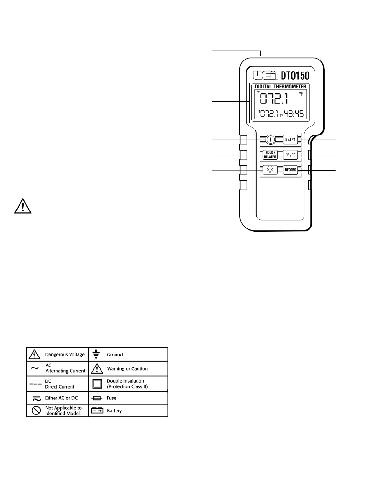
C o n t r ols and Indicators
1. T h e r m o c ouple Po r t : Polarized blades from miniature
thermocouple probe plugs in here.
2. LCD Display: Displays temperature and relative clock information.
3. Power Switch: Powers instrument on and off.
4. Hold/Relative Switch: Quick press freezes temperature data.
Long press switches instrument to the relative-zero display mode.
5. Back Light: Powers back light on and off.
6. K/J/T Thermocouple Select Switch: Changes input reference
for thermocouple ty p e .
7. ˚F/˚C Mode Select Switch: Toggles display mode from degrees
Celsius to degrees Fa h r e n h e i t .
8. Record Mode Select Switch: Starts record mode (relative clock).
Cycles display to indicate either the current temperature, the
m a ximum temperature, or the minimum temperature along with
the hour and minute it was recorded.
Introduction
The DT 150 or DTO 150 is ideal for technicians working in HVAC/R
maintenance, appliance repair, labora t o ry environmental monitoring,
process control, agriculture, and numerous other purposes.
Features include
• Measures from -328 to 2498˚F (-200 to 1370˚C)
• Record mode with relative clock
• Relative zero displays change in temperature
• Hold function
• Switchable ˚F or ˚C
• Back light
Safety Notes
Before using this meter, read all safety information carefully. In
this manual the word "WARNING" is used to indicate conditions
or actions that may pose physical hazards to the user. The word
"CAUTION" is used to indicate conditions or actions that may
damage this instrument.
WARNING!
Exceeding the specified limits of this meter is dangerous and can
expose the user to serious or possibly fatal injury.
• Read the safety precautions associated with the equipment being
tested and seek assistance or advice when performing
unfamiliar tasks.
• Place ONLY thermocouples (type K, J, or T) in the DT150
or DTO150 thermocouple ports.
• Make sure your DT150 or DTO150 is set for the proper
thermocouple type you are using.
• Be sure the thermocouple you are using can withstand the
temperature extreme it may be exposed to in your service task.
• Maintain your DT150 or DTO150 according to the schedule
provided and calibrate it regularly.
International Symbols
DTO150-MAN P. 1
1
2
3
4
5
6
7
8
Page 3

Within these categories you’ll find numerous design differences that
can improve the accura c y or temperature range of your measurement.
Your DT 150 accepts thermocouples that employ quick connecting
minature plugs. These plugs are generally color-coded to identify the
thermocouple type (K, J or T) you are using. The following table illustra t e s
the color codes and advantages of the optional thermocouples that ca n
be used:
Hold/Relative Operation
Quickly press and release the button marked “Hold/Relative” to freeze
(hold) the data displayed on the screen. “HOLD” will appear at the top
of the display. Data will remain on the screen until it is pressed again.
This feature is blocked while the record mode is active.
To display the change in temperature only (relative zero), press and
h o l d - d own the “H o l d / Re l a t i ve” button for approximately two seconds.
“REL” will appear at the top of the display. If there is no change in
t e m p e r ature the display will remain at zero. Any rise in temperature will
be displayed as positive numbers and any decrease will be displayed as
negative numbers. Thermocouple and scale selections are locked in place
when the relative mode is selected. Briefly press the “H o l d / Re l a t i v e”
button again to return to real-time temperature measurement.
NOTE: To determine the temperature rise in a air conditioner’s
evaporator, place a thermocouple firmly on the refrigerant line at
the inlet of the evaporator and initiate the relative function. Move the
thermocouple to the outlet and note the reading. Measurements should
be taken as close to the radiator as possible. Keep in mind that any
change in outlet temperature may be preceded by a change in inlet
temperature. Additional readings may be required.
Changing Temperature Scales
Temperature readings are easily toggled between the Fahrenheit and
Celsius scales by pressing the “˚F/˚C” button. Scales cannot be changed
when either the relative or record mode is active.
Backlight Operation
Press the “ “ push-button to view on-screen data in low light areas.
The internal backlight illuminates the LCD for 30 seconds then shuts
itself off. Pressing the “ “ button again will NOT turn off the light.
Recording Measurements
Temperature information can be recorded using the integral relativetime-clock. When “RECORD” is selected a stopwatch-style clock
appears in the lower right portion of the screen displaying the total time
(starting at 00:00) in hours and minutes since the “RECORD” button
was pushed. The icon “REC” also appears along the top of the display.
All selections except the backlight and power are locked in place until
you exit the record mode.
Press “RECORD” once to initiate the record mode. The real-time
temperature reading is displayed along with a relative clock that
indicates how long the record mode has been running.
Operating Instructions
The DT150 is a single input digital thermometer that measures
temperature using appropriate thermocouples. Tables indicating
the range and accuracy of this thermometer are provided in the
specification section. The type and quality of your thermocouple will
limit the range and accuracy of this thermometer are provided in the
Specification section. The type and quality of your thermocouple will
limit the range and accuracy of your measurement. The LCD display
indicates the temperature being measured along with relative clock and
mode selections. If no thermocouple is plugged in, four dashes will
appear in the temperature data screen. A low battery indicator is also
displayed as appropriate. This instrument operates and updates silently.
Thermocouples use two dissimilar metals in their wiring to develop a
voltage that changes under varying temperature conditions. The DT150
uses this voltage to determine the temperature at the thermocouple’s
two-wire junction. It is therefore critical to the accuracy of your reading
that any uninsulated portion of the thermocouple does not come in
contact with a live electrical circuit of even minimal voltage.
When the thermocouple type and the temperature scale selections are
used for more than 10 seconds, they are stored in memory and will be
set as the default the next time the instrument is turned on.
Power ON/OFF
Press the power “ON/ OFF ” button briefly to turn the instrument on or off.
The Auto-Pow e r - Off function will come on unless deliberately overridden.
Auto-Power-Off
The DT150 or DTO150 will shut off automatically in approximately 90
minutes. For recording or operating over longer periods of time you can
override the auto power off function. To override the A u t o - P ow e r - O f f
function. To override the Auto-Pow e r - Off function:
1. Press and hold down the “Hold/Relative” button
2. Press the “ON” button - Observe an “N” in the middle of the
screen, indicating the “Auto-Power-Off” function has been
overridden
3. Release the “Hold” button
K/J/T Selection
The button marked “K/K/T” is used to match the DT150 with the type
of thermocouple you are using. After initial power-up, press the “K/J/T”
button to cycle through those configuration options until the proper
selection is displayed on the left side of the LCD. This selection must be
matched with the type thermocouple installed for accurate readings.
This selection can not be changed while the record mode is active.
To get the most form your DT150 or DTO150, use a thermocouple that
best suits your needs. The material you’re measuring and its
accessibility will determine which thermocouple is right for the job.
Thermocouples are often divided into these three categories:
1. Submersible (two wire junction fully enclosed in a metal jacket).
2. Contact (two wire junction exposed and mounted to make solid
contact with a surface).
3. Air (two wire junction recessed in a thermally insulated air baffle).
DTO150-MAN P. 2
Type K Yellow Wide range (-328˚ to 2498˚F with
good accuracy throughout range
Type K Black High accuracy from 32˚ to 940˚F
Chromium free
Type T Blue High accuracy from -328˚ to 730˚F
Economical material for distant runs
Page 4

Cycle through the currently measured temperature and the maximum
and minimum recorded temperatures by repeatedly pressing the record
button. Icons will appear on the display to indicate which mode you
are viewing:
• Maximum (REC and MAX icons)
• Minimum (REC and MIN icons)
• Current Temperature (REC icon only)
M a i n t e n a n c e
Periodic service
WARNING!
Repair and service of this instrument is to be performed by qualified
personnel only. Improper repair or service could result in physical
degradation of the meter. This could alter the protection from
electrical shock and personal injury this meter provides to the
operator. Perform only those maintenance tasks that you are
qualified to do.
These guidelines will help you attain long and reliable service from
your meter:
1. Calibrate your meter annually to ensure it meets original
performance specifications.
2. Keep your meter dry. If it gets wet, wipe it dry immediately. Liquids
damage electronic circuits.
3. Whenever pra c t i cal, keep the meter away from dust and dirt, which
can cause premature wear.
4. Although your meter is built to withstand the rigors of daily use, it
can be damaged by severe impacts. Use reasonable caution when
using and storing the meter.
NOTE: When servicing the meter, use only the replacement parts specified.
Battery: 9V, NEDA 1604 or IEC 6LR 61
Cleaning and Decontamination
Periodically clean your meter’s case using a damp cloth. DO NOT use
abrasives, cleaning solvents or strong detergents, as they may damage
the finish or affect the reliability of the structural components.
Battery Replacement
Always use a fresh replacement battery of the specified size and type.
Immediately remove the old or weak battery from the meter and
dispose of it in accordance with your local disposal regulations. Old or
defective batteries can leak chemicals that corrode electronic circuits.
WARNING!
To avoid electric shock, be sure to turn off the meter’s power before you
remove or install batteries.
To install a new battery, follow these procedures:
1. Remove the thermocouple from the top of the instrument.
2. Remove the rubber boot by sliding the instrument out toward the
top faceplate cut-out.
3. Lay the instrument face down on a clean, flat surface.
4. Remove the battery cover.
• Apply inward pressure on the side of the battery cover at the
recessed point, toward the slit, while sliding it out.
5. Remove and replace the battery, observing indicated polarity.
WARNING!
Under NO circumstance should you expose batteries to extreme heat or
fire as they may explode and cause injury.
NOTE: If you do not plan to use the meter for a month or more,
remove the battery and store it in an area that won’t be damaged by a
leaking battery.
Calibration
When properly maintained, your DT150 will maintain an accuracy
specification of up to 0.1% of the reading. To ensure your instrument
is performing at its peak, send it to the UEi factory or a qualified
instrument calibration facility for annual calibration.
Tro u b l e s h o o t i n g
This instrument contains no user serviceable parts beyond those listed
in the troubleshooting table. In the event your instrument is physically
damaged or does not function properly after taking the listed action,
please return the instrument to UEi following the warranty and
service instructions.
DTO150-MAN P. 3
Page 5

S p e c i f i c a t i o n s
Optional Accessories
Optional
4’ Standard oven clip (Type-J) . . . . . . . . . . . . . . . . . . . . . . . . . . .ATT19
Liquid immersion probe w/pointed tip (Type-J) . . . . . . . . . . . .ATT26
Disposable/reusable 4’ wire probe (Type-J) . . . . . . . . . . . . . . . .ATT27
Liquid immersion probe and handle, 8” pointed tip (Type-J) .ATT30
Air probe (Type-J) . . . . . . . . . . . . . . . . . . . . . . . . . . . . . . . . . . . . .ATT49
4’ Standard wire probe (Type-K) . . . . . . . . . . . . . . . . . . . . . . . . .ATT29
4’ Standard wire probe w/FDA approved insulation (Type-K) .ATT29A
Surface probe and handle and 8” tip (Type-K) . . . . . . . . . . . . .ATT36
6” Liquid probe and handle (Type-K) . . . . . . . . . . . . . . . . . . . . .ATT100
Soft Carrying Case . . . . . . . . . . . . . . . . . . . . . . . . . . . . . . . . . . . .AC315
Hard Carrying Case . . . . . . . . . . . . . . . . . . . . . . . . . . . . . . . . . . .AC504
Hard Carrying Case . . . . . . . . . . . . . . . . . . . . . . . . . . . . . . . . . . .AC506
DTO150-MAN P. 4
If I See This I Should Then Take This Corrective Action
Malfunction Check For
Instrument Battery Voltage Replace low battery
does not turn on Battery clip Ensure clip grips battery posts tightly
Dashes appear Thermocouple Insert missing thermocouples
in data screen
Dashes appear in Thermocouples Measure resistance of thermocouple
data screen with continuity to ensure it is not broken internally
thermocouples - Replace if required
inserted Thermocouple Clean corrosion of debris off of
connection ports thermocouple - Reinsert
Temperature drifts Thermocouple Ensure thermocouple type matches
from known value type the displayed icon
in a controlled Moisture, Clean and dry thermocouple
environment corrosion or blades - Allow thermocouple plug
debris on to air dry
thermocouple
blade
Defective Confirm defect with known good
thermocouple thermocouple - Replace if required
Relative clock will Thermocouple Record will not start without
not start when properly inserted thermocouples inserted
“RECORD” button
is pressed
Dashes appear Open Check for intermittent or momentarily
during review of thermocouple removed thermocouple
maximum recorded
value
Data continues to “HOLD/RECORD” Observe “HOLD” or “REC” icons on
update when is not being LCD - Press button firmly
“HOLD” or fully pressed
“RECORD” are
initiated
Instrument turns Auto power off Defeat auto-power-off - Follow
off during recording is shutting off procedures outlined in
instrument Operating Instructions
Height x Length x Width 7” x 3-3/8” x 1-7/8”
(boot included) (178 x 86 x 48 mm)
Weight 14.8 oz (420 g)
Battery Standard 9 Volt (NEDA 1604, IEC 6LR61)
Alkaline recommended
Supplied thermocouple
Model DT150 4’ type-K multipurpose wire probe
(UEi P/N ATT29A)
Model DTO150 4’ type-J oven clip thermocouple
(UEi P/N ATT19)
Operating and 32˚ to 122˚F (0˚ to 50˚C)
storage conditions at 0 to 85% RH
Page 6

Limited Warranty
The DT 150 / D TO 1 50 is warranted to be free from defects in materials and workmanship for a
period of three years from the date of purchase. If within the warra n ty period your instrument
should become inoperative from such defects, the unit will be repaired or replaced at UE i ’ s
option. This warra n ty covers normal use and does not cover damage which occurs in
shipment or failure which results from alteration, tampering, accident, misuse, abuse, neglect
or improper maintenance. Batteries and consequential damage resulting from failed batteries
are not covered by warra n ty.
Any implied warranties, including but not limited to implied warranties of merchantability
and fitness for a particular purpose, are limited to the express warranty. UEi shall not be
liable for loss of use of the instrument or other incidental or consequential damages,
expenses, or economic loss, or for any claim or claims for such damage, expenses or
economic loss. A purchase receipt or other proof of original purchase date will be required
before warra n ty repairs will be rendered. Instruments out of warra n ty will be repaired (when
r e p a i r able) for a service charge. Return the unit postage paid and insured to:
1-800-547-5740 • FAX: (503) 643-6322
www.ueitest.com • Email: info@ueitest.com
This warranty gives you specific legal rights. You may also have other rights which vary from
state to state.
DT150/DTO150
Digital Thermometer
Copyright © 2007 UEi DTO150-MAN 1/07
PLEASE
RECYCLE
 Loading...