

Page 1
1-800-547-5740 • Fax: (503) 643-6322
www.ueitest.com • email: info@ueitest.com
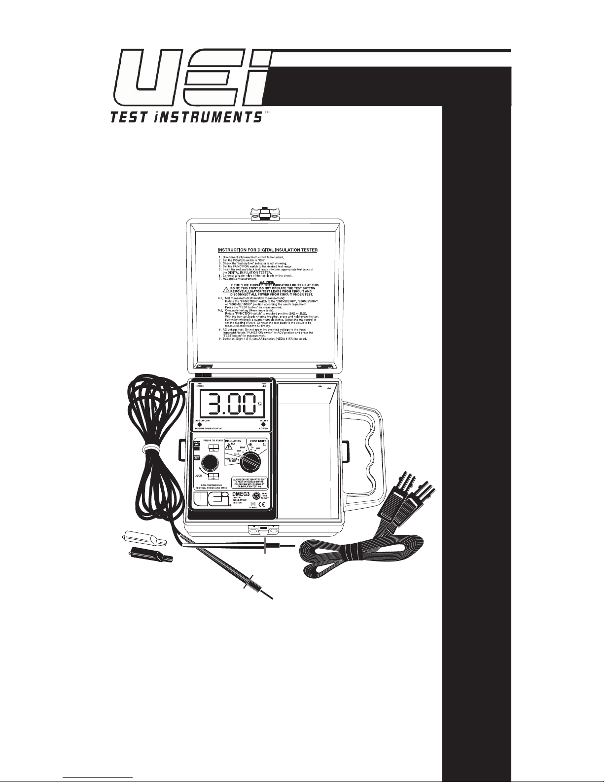
DMEG3/IRT3
Insulation Resistance Tester
INSTRUCTION MANUAL
Page 2

TABLE OF CONTENTS
Introduction ..........................................................................................1
Safety ....................................................................................................... 2
International Symbols ....................................................................5
Controls
Power Switch ...................................................................................6
Rotary Function Select Switch ......................................................6
Press to Test .................................................................................... 6
Resistance Null Adjust ...................................................................6
Indicators
LCD Display ..................................................................................... 8
Power On Indicator ........................................................................ 8
Live Circuit Indicator ..................................................................... 8
Operation
Installing Test Leads ....................................................................... 9
Detecting AC Voltage ...................................................................10
Measuring AC Voltage .................................................................11
Measuring Continuity ..................................................................12
Measuring Insulation Resistance ................................................ 13
Temperature Correction .............................................................. 16
Preparing Equipment Under Test ..............................................18
To Make An Extended Term Analysis ........................................23
Maintenance
Service ............................................................................................ 24
Cleaning ......................................................................................... 24
Battery Replacement .................................................................... 24
Fuse Replacement ........................................................................25
Specifications
Measurement Limits ....................................................................26
General Specifications .................................................................26
Specification Table .......................................................................27
Warranty and Service Information ........................................... 30
i
Page 3

Introduction
Your UEi Megohmeter allows you to predict, prevent and
identify insulation failures that can cause appliance failure, stop
production, create power problems and even put lives at risk. It
quickly tests insulation integrity on motors, power distribution
systems and other installed wiring.
All insulation has a limited life span and environmental factors
such as heat, cold and airborne chemicals can rapidly decrease
an insulating material’s predicted life. Use this instrument to
help you quickly and safely determine your insulation’s integrity.
Features include
• Large digital display that shows the test function along
with the measured value on the DMEG3 or a high-contrast
analog display on the IRT3
• AC Voltage measurement to 600 Volts
• Insulation resistance readings from 0 to 2000 Megohms
with the DMEG3 or 200 Megohms with the IRT3
• Three test-voltage ranges (250, 500, 1000 V DC)
• Live circuit (external voltage applied) warning light
• Fuse protected against accidental misuse
• Precision resistance measurement to 0.01 ohms with
audible continuity (DMEG3 only)
• 200 mA short-circuit continuity test current for high
accuracy (DMEG3 only)
• Precision, low resistance test leads
(1000 Volt CAT III rated)
• Audible continuity (DMEG3 only)
• Green LED power-on indicator (DMEG3 only)
• Low battery indication/detection
• Maintains rated voltage on cables with up to
1 mA leak-rate
• Automatic, post-test cable discharge
• Rugged, compact case with latching cover to keep
the elements out
1
Page 4

Safety Tips
Before using this instrument, read all safety information
carefully. In this manual the word “WARNING” is
used to indicate conditions or actions that may pose
physical hazards to the user. The word “CAUTION” is
used to indicate conditions or actions that may damage
this instrument.
This Megohmeter is designed and manufactured in
accordance with the following organizational standards:
• IEC1010 CAT III, BS 16th Edition
• EN61010
• IEC Publication 348
These guidelines apply specifically to your instrument:
• DO NOT attempt to measure any voltage that exceeds the
category based rating of this meter (CAT III, 600 Volts)
• DO NOT attempt to use this meter if either the meter or
the test leads have been damaged. Return the damaged
meter to UEi for repair or replace your test leads
• Ensure meter leads are fully seated and operable by
making a quick continuity check of the leads prior to
making voltage or insulation resistance measurements
• Keep your fingers away from the test lead’s metal probe
contacts when making measurements. Always grip the
leads behind the finger guards molded into the probes
• DO NOT open the bottom of the meter to replace
batteries or the fuse while the probes are connected
to the meter or this meter is on
2
Page 5

This meter was designed for use by service professionals
who know the hazards associated with their trade. Exceeding
the specified limits of this meter is dangerous and can cause
serious injury. To ensure safe and appropriate use, please
observe the following safety guidelines:
• Follow manufacturer’s specified testing and
troubleshooting procedures for the equipment you are
working on
• Protect yourself from direct contact with voltages above
60 volts DC or 25 volts AC, as they may constitute a
serious shock hazard
• Always turn off power to a circuit (or assembly) under
test before cutting, unsoldering, or breaking the current
path. Even small amounts of current can be dangerous
• Always disconnect the live (normally red) test lead before
disconnecting the common (normally black) test lead
from a circuit
• In the event of electrical shock, ALWAYS bring the victim
to the emergency room for evaluation, regardless of the
victim’s apparent recovery
Electrical shock can cause an unstable heart rhythm
that may need medical attention.
3
Page 6

Higher voltages require greater awareness of physical safety
hazards. When it’s possible to make clip-on connections to the
circuit under test, make the connections without power applied:
1. Turn off the power to the circuit under test.
2. Set the meter to the AC 600 Volt position.
3. Connect the test leads to the meter and then to the
circuit under test.
4. Reapply power.
5. Record measurement or adjust equipment as necessary.
6. Turn off power and disconnect test leads.
If any of the following indications occur during testing, turn off
the power source to the circuit under test:
• Arcing • Extreme heat
• Flame • Smell of burning materials
• Smoke • Discoloration or melting of components
WARNING!
If any of the above conditions occur, DO NOT attempt to
remove the meter leads from the circuit under test. The
leads, meter, or circuit under test may have degraded to the
point that they no longer provide protection from the voltage
and current applied. If any of these erroneous readings are
observed, disconnect power immediately. Recheck the physical
condition of the test instrument, equipment and all settings
and connections.
4
Page 7
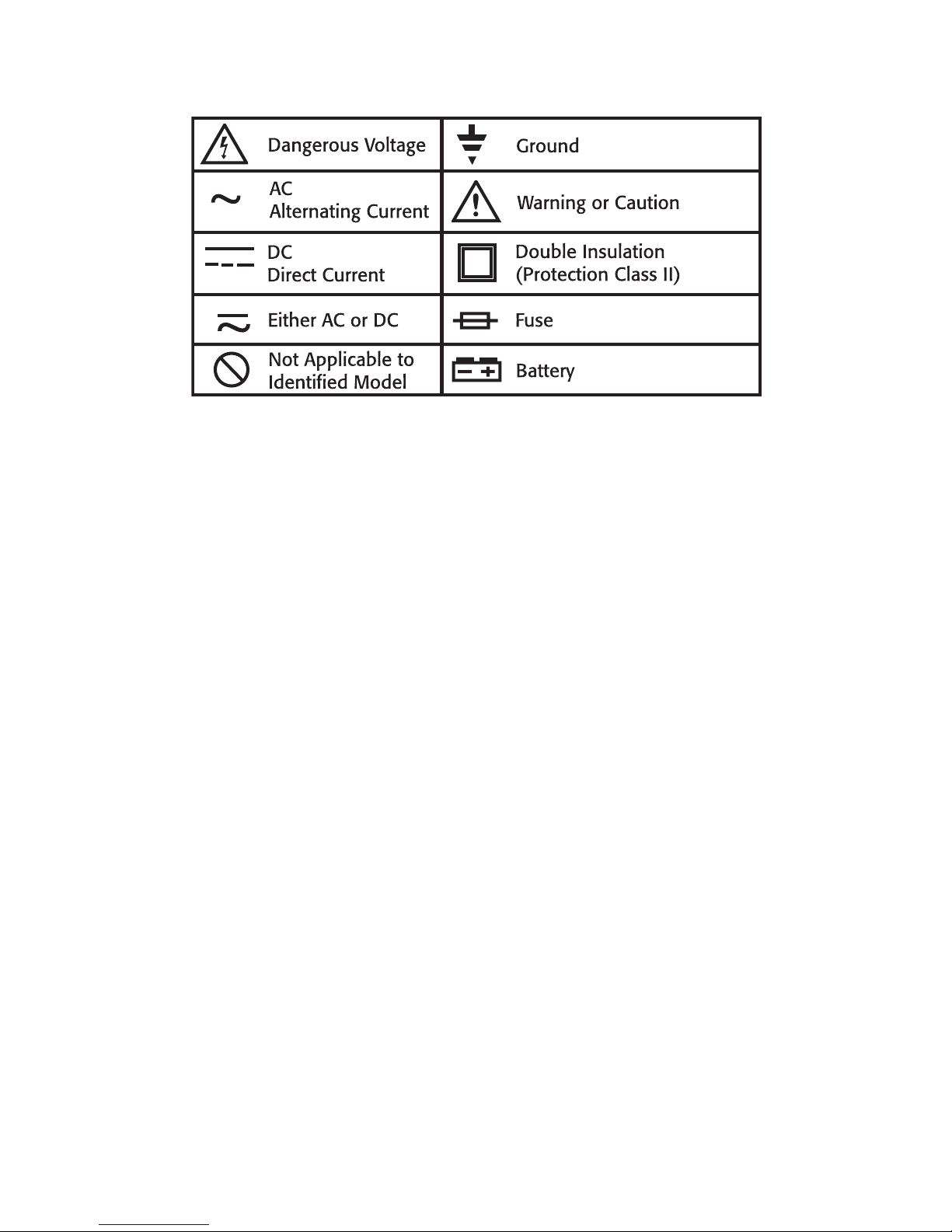
International Symbols
5
Page 8
6
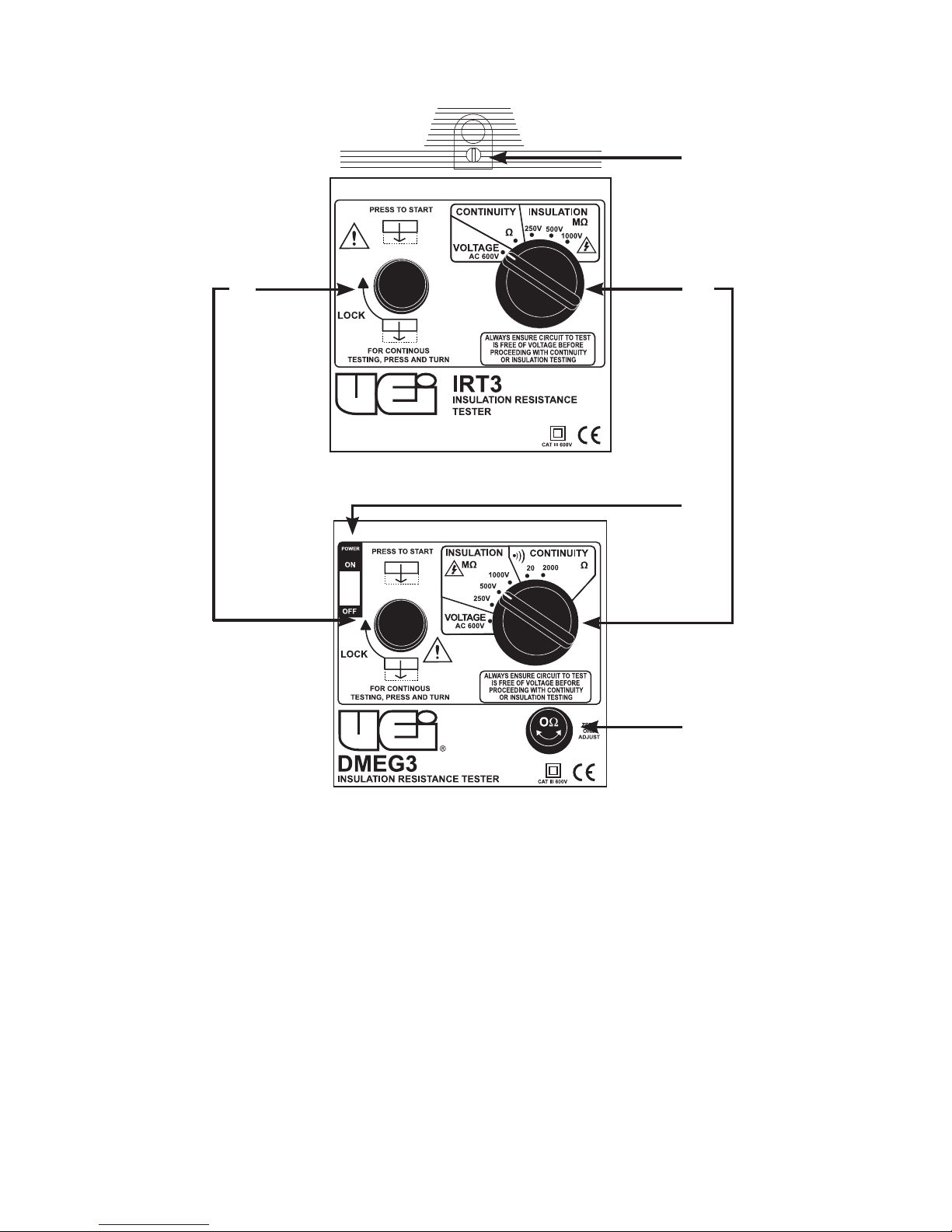
Controls and Indicators
(IRT3)
(DMEG3)
1
2
3
4
4
Page 9

1. Power Switch: Turns instrument power off and on.
2. Rotary Function Select Switch: Selects measurement
mode and scale.
3. Press to Test: Press this button down to initiate any
measurement function. Turn to the right while pressing to
lock the button into the test mode.
4. Resistance Null Adjust:
(DMEG3) Used to adjust meter to indicate 0.00 ohms with
the function select switch in the continuity position, the
red and black leads clipped together and the “Press to
Test” button pressed.
(IRT3) Used to pre-adjust needle movement to 0 volts
(infinite ohms) prior to use. Or you can adjust meter
to indicate 0 ohms on the green scale with the function
select switch in the continuity position, the red and
black leads clipped together and the “Press to Test”
button pressed.
7
Page 10
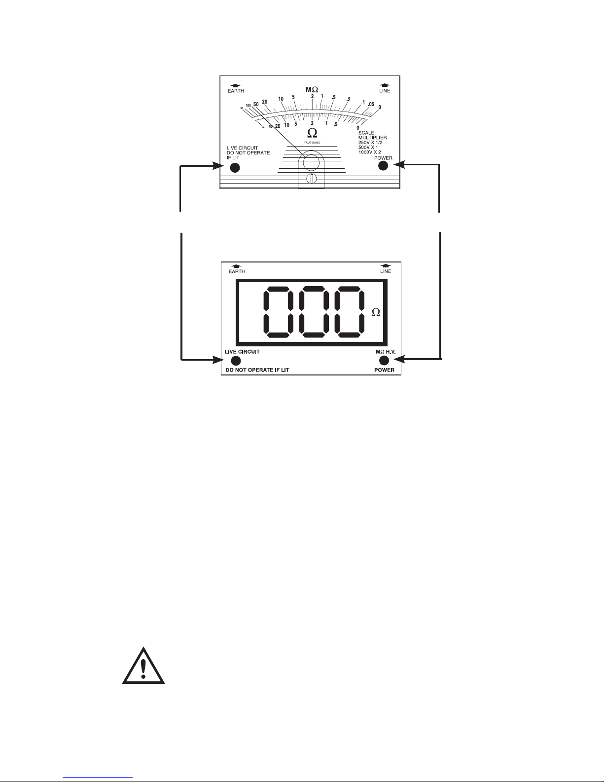
IRT3 (Fig 1)
• Red light indicates that the “Press to Test” switch is pressed
• Voltage is tested without pressing “Press to Test” switch
DMEG3 (Fig 2)
• Green light indicates that the ON - OFF switch is turned on
• Orange indicates high voltage is being generated by the
Megohmeter for insulation resistance testing
CAUTION!
Live Circuit Indicator - Indicates that live voltage is present
on the test leads. The ONLY measurement you can take is AC
Voltage if this light is lit.
(Fig 1)
(Fig 2)
Analog Display (IRT3)
LCD Display (DMEG3)
Live circuit
Power ON
8
Page 11

Operating Instructions
Prior to operating your insulation resistance tester, inspect your
instrument for:
1. Cracks or damage to the housing.
2. Water intrusion or condensation on the display.
3. Damaged test leads.
4. Low batteries.
• Check the IRT3 by pressing the Press to Test
button - the red LED light should flash rapidly if
batteries are good
• Check the DMEG3 by turning the instrument
power on and pressing the Press to Test button
if defective, “Lo Bat” will be displayed on the LCD
5. Properly installed and fully seated test leads.
• Black test lead is inserted in the “EARTH” jack
• Red test lead is inserted in the “LINE” jack
Replace the test leads if there is any visible or measurable
damage. Replace batteries if needed (refer to the maintenance
section of this manual). If there is any damage to the
instrument, it must be returned to UEi for repair.
Installing Test Leads
Test leads must be installed prior to any measurement or
detection procedure.
1. Connect the black test lead to “EARTH”, ensuring it is
fully seated.
2. Connect the red test lead to “LINE”, ensuring it is
fully seated.
9
Page 12

Detecting AC Voltage
Any time AC voltage is present on the test leads, the “Live
Circuit” indicator light will illuminate. This voltage detection
feature works regardless of battery condition or powering on
the instrument. With test leads installed:
1. Ensure power is off (DMEG3) and the Press to Test
is NOT pressed.
2. Connect black test lead to the grounded or neutral side
of the circuit.
3. Connect red test lead to the hot or powered side of
the circuit.
4. Observe “Live Circuit” lamp.
• Lamp illuminated: circuit is live, DO NOT test
continuity or megohms
• Lamp off: circuit is not live, testing may proceed
NOTE: Connecting the black and red test leads to the specific
sides of the circuit indicated is not critical to the measurement.
Connecting the black “EARTH” test lead to ground first is a
safety discipline that can reduce the risk of a shock hazard to
the operator.
10
Page 13

Measuring AC Voltage
Voltage levels of up to 600 volts AC can be measured with
your insulation resistance tester. With test leads installed:
1. Ensure power is on (DMEG3).
2. Place rotary function select switch to the
“AC 600 V” position.
3. Connect black test lead to the grounded or neutral
side of the circuit.
4. Connect red test lead to the hot or powered side of
the circuit.
5. Apply power to the circuit under test.
6. Press and hold (or lock) the “Press to Test” button.
7. Observe voltage level.
8. Release the “Press to Test” button, remove power to the
circuit under test and then disconnect test leads.
WARNING!
Connecting alligator clips to live circuits presents a shock
hazard. Insulation on these clips deteriorates over time and
often wears thin from the inside, through use,. If live voltage
must be tested, connect the black clip to a KNOWN ground
then use the red test lead without the alligator clip attached
to check the hot side of the circuit. Use protective clothing and
equipment when appropriate.
11
Page 14

Measuring Continuity
Continuity testing allows you to quickly determine if two or
more points are connected electrically and it allows you to
check for excessive resistance across contacts. With its high
resolution, you can compare input to output windings on
transformers or help identify a motor-type by checking the
resistance of its windings. With test leads installed:
1. Ensure no power is applied to the circuit under test
(see detecting AC voltage).
2. Ensure power is on (DMEG3).
3. Place rotary function select switch to the “Continuity”
position. (the DMEG3 has two continuity ranges)
• 2000 ohm for high-impedance testing
• 20 ohm for low impedance, high accuracy testing
4. Test continuity operation by shorting test leads together
and pressing the “Press to Test” button.
5. Connect black test lead to one side of the circuit
(i.e., winding or contact).
6. Connect red test lead to the other side of the circuit
(i.e., other end of the winding).
7. Press and hold (or lock) the “Press to Test” button.
8. A continuity tone will sound (DMEG3 only) if resistance
is below 10 ohms.
9. Observe ohm value.
NOTE: High precision resistance (continuity) readings can
be improved by using the null adjust feature to offset the
resistance value of the test leads. To offset this resistance value,
follow the instructions through step 4, then adjust the null
adjustment knob to indicate zero on the dial or digital display.
Your resistance or continuity readings will now display only
the resistance in the circuit, not the combined resistance of the
leads and the circuit.
12
Page 15

Measuring Insulation Resistance
Insulation resistance testing (IRT) is the process of evaluating
an insulating material’s integrity. Any time you use IRT
procedures; you will be applying a relatively high DC voltage
(250, 500 or 1000 Volts) to two separate conducting paths. For
example, the “conducting paths” might be the hot and neutral
wires in a cable set. With this voltage applied, your meter will
measure the extremely small amount of current that flows
between the two paths. Using the principles of Ohm’s law, the
resistance value is displayed.
What needs to be tested: All insulating materials begin
deteriorating from the day they are made. Knowing this, a
wide variety of insulation specifications have been created to
accommodate different environments in which they will be
used. Some of those ratings refer to environmental conditions
such as indoor use, outdoor use, chemical resistant, high or low
temperature, maximum voltage or current ratings and many
more. When insulating materials are subjected to conditions
other than what they are rated for, and as time takes its toll,
deterioration accelerates.
Frequently the life span of an insulating material is known to
be less than the life span of the appliance it is being used in.
Motor windings are a good example. Industrial manufacturing
equipment, commercial refrigeration systems and other
processes require predictive and preventive maintenance (PM)
procedures to ensure uninterrupted operation. Insulation
resistance testing should be part of that maintenance process.
IRT procedures are recommended, and often documented by
numerous engineering and maintenance organizations such as
IEEE, NETA and IEC. You can access these organizations and the
documents they have produced related to insulation resistance
testing through the internet. Some documents are fee-based.
13
Page 16

You will commonly find IRT procedures performed in
these tasks:
• Predictive/preventive maintenance on installed motor
windings - recommended for all motors 750 watts
(1 HP) or greater
• Predictive/preventive maintenance on commercial
HVAC compressors
• Testing integrity of insulation on buried cables
powering well-pumps
• Verifying safety standards for appliances and
biomedical equipment
• New-installation verification
• Troubleshooting electrical faults
• Fire and flood damaged building non-destructive
inspections
• Electrical product manufacturing quality control
Insulation Resistance Testing Methods: Insulation
resistance testing can be performed using a variety of methods.
The proper method will be determined by the circuit or
cable’s rated voltage capacity, by the purpose of your test
(troubleshooting, preventive maintenance, etc.) and by the
function of the circuit you are testing.
Each motor, cable, appliance or other circuit being tested will
have its own unique characteristics resulting from its type of
insulation, where it’s installed and other criteria. Accordingly,
specific test values cannot be documented in this manual.
Instead, the general behaviors-under-test and some of the
generally accepted “rules of thumb” will be provided to assist
you in establishing your own test and maintenance practices.
14
Page 17

Cable or Conductor Rated Voltage
Whenever possible, use the equipment manufacturer’s
recommended test voltage. Most conductors (shielded,
paired, etc.) have a voltage limit printed on the outer
insulation that can be used in the absence of a manufacturer’s
recommendation. When using the rating printed on the outer
jacket, use two times the value, up to the 1000 volts maximum.
Commonly used voltages.
Humidity and Dew Point
In oder to make an accurate assessment of a motor’s life
expectancy, conditions must be similar each time it’s tested.
If the equipment you are testing is at or below the dew point
temperature, water-condensation may collect around the
windings and connections. Condensation can make a motor
appear to be failing rapidly when it actually has years of
serviceable-life left.
Humidity also affects readings at the same time it affects
insulation resistance when the motor is running. Seasonal
deviations in insulation resistance may be noted, but should
not be neglected. The same motor may perform fine in winter
when humidity is low and begin to fail in summer when
humidity increases.
Humidity and dew point information is available for some
areas by phone (see your local listing). UEi also makes special
purpose instruments to give you accurate and instant humidity,
dew point and temperature information.
Specified Cable/Equipment
Voltage Rating
50-100
100-440
440 and above
Megohmeter DC Voltage
Level
250
500
1000
15
Page 18

Temperature Correction
Temperature has a very large impact on your insulation
resistance values. When using your meter for predictive
or preventive maintenance tasks, the readings must be
“temperature corrected” to 20˚C (68˚F).
The rule of thumb is, insulation resistance changes by a
factor of 2 for every 10 degrees of change in Celsius-scaled
temperature. That means that a cable that measures 150
Megohms at 20 degrees Celsius (or 68 degrees Fahrenheit)
will likely measure 75 Megohms at 30 degrees Celsius ( or
86 degrees Fahrenheit). Accordingly you would record 150
Megohms on your PM record (75 Meg x 2). Use the following
chart to adjust for this correction factor (Fig 3).
Temp
in C
10
12
14
16
18
20
22
24
26
28
30
32
34
Temp
in F
50
54
57
61
64
68
72
75
79
82
86
90
93
Multiply
Reading by
0.5
0.6
0.7
0.8
0.9
1.0
1.2
1.4
1.6
1.8
2.0
2.4
2.8
Temp
in C
36
38
40
42
44
46
48
50
52
54
56
58
60
Temp
in F
97
100
104
108
111
118
118
122
126
129
133
136
140
Multiply
Reading by
3.2
3.6
4.0
4.4
4.8
5.2
5.6
6.0
6.4
6.8
7.2
7.6
8.0
16
Page 19

NOTE: UEi makes a number of temperature products to use in
reading motor temperatures.
Temperature Correction Table
(Fig 3)
17
Conductor Temperature in ˚F
Multiply By
Page 20

Preparing Equipment Under Test
Isolation is a key factor in properly testing any insulation
resistance value. Whether you are testing a motor winding,
transformer winding or a cable, you must ensure that the
component you are evaluating has no path to ground or other
circuits. Contactors and switches must be open and terminal
connections must be removed prior to testing.
Your insulation resistance tester is designed to place the DC
charge on the “LINE” terminal while the “EARTH” terminal
often shares the grounded contact with all other components.
You can only test one cable, winding or component at a time,
but they ALL need to be tested independently (Fig 4).
(Fig 4)
18
Page 21

When more than one connection is called for, connect the test
points together.
E = Earth L = Line
Single Phase Transformer Connection Sequence Table
Motor Connection Sequence Table
Insulated 3-Conductor Cable Connection Sequence Table
Shielded 3-Conductor Cable Connection Sequence Table
Sequence L1 L2 L3 Shield
1 E L E E
2 L E E E
3 E E L E
4
(Remove Shield E E E L
from Ground)
Sequence L1 L2 L3
1 E L E
2 L E E
3 E E L
Sequence Stator Field Ground
1 E L E
2 L E E
3 L E
4 E L
Sequence X1 H2 Ground
1 E L E
2 L E E
3 L E
4 E L
19
Page 22

60-Second (spot reading) Method
Spot readings are often used as predictive/preventive
maintenance tools. Readings are generally taken at regular
intervals (quarterly, semi-annually, etc.) and recorded on a
chart that stays with the equipment being tested. To make an
analysis of a motor using this method:
1. Check and record equipment temperature.
2. Check dew point temperature of the ambient
air - equipment under test must be above dew point
temperature for accurate results.
3. Ensure no power is applied to the equipment under
test and all connections are removed in order to
totally isolate the motor, cables or equipment from
other circuits.
Use the connection tables to determine where
to make connections.
• If you are testing a motor, the brushes must be
removed prior to testing
• Connect all components that are NOT
being tested, including motor housing, to
ground (EARTH)
• Test Field and Stator windings independently
4. Turn your instrument power on (DMEG3).
5. Place rotary function select switch to the INSULATION
position, with the correct voltage selected - Use the same
voltage every time.
6. Make connections according to the sequence tables
provided or as your circumstances require.
7. Using a stopwatch or watch with a second hand, begin a
60-second test at the same time you press and hold (or
lock) the “Press to Test” button.
20
Page 23

8. At the end of 60-seconds, read and record the insulation
resistance value.
9. Apply temperature correction factor and record results
on PM Chart (Fig 4).
This chart interprets some possible data.
PM Data
(Fig 3)
21
Megohms
Humidity Induced
Dip
Failed Motor
Replaced
Motor Replaced
Before Failure
Uncharacteristic change
indicates imminent
failure
Page 24

Extended Term Analysis
These methods incorporate comparisons of resistance values
recorded at different points of time (up to ten minutes). They
can provide useful information about the condition of your
equipment even if PM records are not available.
Generally speaking, the resistance measured at the end of 5
or 10 minutes should be higher than it was at one minute. The
best way to determine a good or bad reading for your specific
application is to solicit information from the manufacturer or
evaluate new and progressively older equipment.
60-30 Testing
The ratio of a reading recorded at 60 seconds compared to
that recorded at 30 seconds is one method that gives you
a Dielectric Absorption Ratio (DAR). This ratio provides you
with the Polarization Index (PI) when you divide the reading
observed at the longer term by that of the shorter. The rule
of thumb regarding this index (60-second reading divided by
30-second reading) is that it has to be higher than “one” to
be acceptable. Anything that has a ratio under 1.25 should be
watched carefully and anything over 1.4 is good. Because of
the time-frames specified, this test can be difficult to perform
and is not commonly used.
10-1 Testing
The methods of obtaining the ratios and index numbers are
the same in this test method as used in the 60-30 test, but the
duration of testing is extended. A measurement is recorded
at 1 minute and another one recorded at 10 minutes.
This Polarization Index table applies to both test methods:
Insulation Condition 60-30 Test PI 10-1 Test PI
Bad Below 1.0 Below 1.0
Unreliable 1.0 to 1.25 1.0 to 2.0
OK 1.4 to 1.6 2.0 to 4.0
Excellent Above 1.6 Above 4.0
22
Page 25

To Make An Extended Term Analysis
1. Check and record equipment temperature.
2. Check dew point temperature of the ambient
air - equipment under test must be above dew point
temperature for accurate results.
3. Ensure no power is applied to the equipment under test
and all connections are removed in order to totally isolate
the motor, cables or equipment form other circuits.
Use the connection tables to determine where to
make connections.
4. Turn your instrument power on (DMEG3).
5. Place rotary function select switch to the “INSULATION“
position, with the correct voltage selected - Use the same
voltage every time.
6. Make connections according to the sequence tables
provided or as your circumstances require.
7. Using a stopwatch or watch with a second hand, begin
your test at the same time you press and hold (or lock)
the “Press to Test” button.
8. At the end of one minute, read and record the insulation
resistance value.
9. Continue testing and record the value at the end of
10 minutes.
10. Evaluate results based on the Polarization Index table.
Following page: Copy and use the following PM data sheets
to record and monitor insulation resistance values of the
equipment you test.
23
Page 26

INSULATION RESISTANCE DATA LOG CARD
EQUIPMENT MAKE SER. NO.
LOCATION PLACED IN SERVICE
COMMENTS
DATE
INFINITY
INSULATION RESISTANCE (MEGOHMS)
.1
.2
.3
.4
.5
.6
.8
1
2
3
4
5
6
8
10
20
30
40
50
60
80
100
200
300
400
500
600
800
1000
Page 27

DATE
READING
TEMPERATURE
AMBIENT EQUIP.
PLOT ADJUSTED READING
CORRECTION
FACTOR
ADJUSTED
READING
RELATIVE
HUMIDITY
Page 28

Maintenance
Service
This instrument contains no user serviceable parts other than
the fuse and batteries. All servicing is to be accomplished
by UEi.
Annual calibration is recommended and can be conducted by
a local calibration facility or at UEi’s factory headquarters in
Beaverton, Oregon.
Cleaning
The external surfaces and empty battery compartment should
be inspected for dirt and contamination on a regular basis.
They can be cleaned using a damp (NOT WET) cloth and a
mild cleaning detergent. Do not allow water, detergent or other
liquids to puddle on the surface or flow inside the instrument.
In the event of accidental liquid intrusion, return the instrument
to UEi for service and evaluation.
Battery Replacement
Battery replacement is required when no powered functions
will operate (also check fuse) or when a low battery indication
is provided (see “controls and indicators” section of this
manual).
Equipment required:
• #2 Phillips screw driver
• Replacement batteries (quantity 6), size: AA
(NEDA #15A) alkaline recommended
WARNING!
DO NOT attempt this maintenance action with power applied
to the instrument either through its test leads or by way of the
“Press to Test” button being pressed.
24
Page 29

To replace the batteries, turn the instrument upside down on a
clean, flat surface to expose battery compartment.
1. Remove the battery cover retaining screw.
2. Apply outward pressure (away from the carrying handle)
on the battery cover and remove it from the instrument.
3. Remove and replace all six batteries at the same time.
Use caution when removing batteries to ensure that any acidic
material leaking from the batteries does not come into contact
with your skin and has not damaged the instrument.
Dispose of batteries in accordance with your local solidwaste disposal regulations. Never expose batteries to high
temperature or incineration.
Fuse Replacement
Fuse replacement is required when no “Press to Test” functions
will operate or when it has been proven defective through
evaluation.
Equipment required:
• #2 Phillips screw driver
• Replacement fuse (quantity 1), replace only with the fuse
type listed on instrument’s back panel
WARNING!
DO NOT attempt this maintenance action with power applied
to the instrument either through its test leads or by way of the
“Press to Test” button being pressed.
25
Page 30

To replace the fuse, turn the instrument upside down on a
clean, flat surface to expose battery compartment.
1. Remove the battery cover retaining screw.
2. Apply outward pressure (away from the carrying handle)
on the battery cover and remove it from the instrument.
3. Remove and replace the fuse with specified replacement
size and type.
4. Replace battery compartment cover.
Specifications
(DMEG3)
1. Insulation Resistance
Measuring 0-200MΩ (250V, 500V DC ±10%)
range Resolution: 1 count/100kΩ
0-2000Ω (1000V DC ±10%)
Resolution: 1 count/1MΩ
Accuracy ±1.5% reading ±5 digit (200MΩ range)
±3% reading ±3 digit (under 1GΩ/2000MΩ)
±5% reading ±5 digit (under 2GΩ/2000MΩ)
Output current 1mA DC min. at 0.25MΩ (250V range)
1mA DC min. at 0.5MΩ (500V range)
1mA DC min. at 1MΩ (1000V range)
Power Max. consumption current approximately
consumption 250mA
26
Page 31

2. AC Voltage
3. Continuity
4. Maximum Voltage
5. Dimension
6. Weight
Ohm range 0-20Ω / Resolution: 0.01Ω / Accuracy: ±1.5% rdg. ±5 dgt.
Ohm range 0-2000Ω / Resolution: 1Ω / Accuracy: ±1.5% rdg. ±3 dgt.
Open circuit 4 DC min.
terminal
voltage
Short circuit 210mA DC min.
terminal
voltage
Power Max. consumption current approximately
consumption 160mA
Buzzer sounds 10Ω (on 20Ω range)
on
Meet IEC-1010 safety requirements Catagory III
6.7 x 6.5 x 3.6 inches (170 x 165 x 92 mm)
with housing front cover
2.2 lb. (batteries included)
Range 0-600V
Resolution 1V
Accuracy ±1.5% reading ±3 digit
Line frequency 40-120 Hz.
range
27
Page 32

Specifications
(IRT3)
1. Insulation resistance
2. AC Voltage
3. Continuity
Megohm 0-50MΩ & ∞ (250 DC V ±10%)
0-100MΩ & ∞ (500 DC V ±10%)
0-200MΩ & ∞ (1000 DC V ±10%)
Accuracy ±5% of indicated value (approximately)
Short circuit 0-50MΩ : 2 DCmA
terminal 0-100MΩ : 2 DCmA
current 0-200MΩ : 2 DCmA
Power Max. consumption current approximately
consumption 190mA
Range 0-600V
Accuracy ±2.5% of full scale
Line frequency 40-1k Hz.
range
Ohm range ±2.5% of full scale
Ohm range ±5% of indiacted value (approx.)
Open circuit 600 DCmV (approx.)
terminal
voltage
Short circuit 240 DCmA (approx.)
terminal
voltage
Power Max. consumption current approximately
consumption 120mA
28
Page 33

4. Maximum Voltage
5. Dimension
6. Weight
Meet IEC-1010 safety requirements Catagory III
6.7 x 6.5 x 3.6 inches (170 x 165 x 92 mm)
with housing front cover
2.1 lb. (batteries included)
29
Page 34

DMEG3/IRT3
Insulation Resistance Tester
Limited Warranty
The DMEG3/IRT3 is warranted to be free from defects in materials
and workmanship for a period of three years from the date of
purchase. If within the warranty period your instrument should
become inoperative from such defects, the unit will be repaired
or replaced at UEi’s option. This warranty covers normal use and
does not cover damage which occurs in shipment or failure which
results from alteration, tampering, accident, misuse, abuse, neglect
or improper maintenance. Batteries and consequential damage
resulting from failed batteries are not covered by warranty.
Any implied warranties, including but not limited to implied
warranties of merchantability and fitness for a particular
purpose, are limited to the express warranty. UEi shall not be
liable for loss of use of the instrument or other incidental or
consequential damages, expenses, or economic loss, or for any
claim or claims for such damage, expenses or economic loss.
A purchase receipt or other proof of original purchase
date will be required before warranty repairs will be rendered.
Instruments out of warranty will be repaired (when repairable) for
a service charge. Return the unit postage paid and insured to:
1-800-547-5740 • FAX: (503) 643-6322
Service: (800) 308-7709
www.ueitest.com • Email: info@ueitest.com
This warranty gives you specific legal rights. You may also have
other rights which vary from state to state.
Copyright © 2004 UEi DMEG3/IRT3-MAN 4/04
 Loading...