

Page 1

Ultra-wideband Location System
Ubisensor30v1
User’s Manual
Written By
Andy Ward
Ubisense Limited
St Andrews House, St Andrews Road, Cambridge CB4 1DL,
ENGLAND
Tel: +44 (0)1223 535170
Fax: +44 (0)1223 448167
Email: [email protected]
WWW: http://www.ubisense.net/
Revised: November 2013
Copyright © 2013 Ubisense Limited, All Rights Reserved
Page 2

Table of Contents
Introduction ................................................................................................................................ 1
Regulatory Information for the United States of America .......................................................... 1
Regulatory Information for Europe ............................................................................................ 1
Regulatory Information for Canada ........................................................................................... 2
Nomenclature ............................................................................................................................ 2
Features of the Ubisensor ......................................................................................................... 3
Installation and Operation Instructions ...................................................................................... 5
Mounting options ................................................................................................................ 5
Powering the Ubisensors ................................................................................................... 5
Setting up a sensor group .................................................................................................. 5
Switching on the Ubisensor ................................................................................................ 6
Calibrating the Ubisensor ................................................................................................... 6
Troubleshooting .................................................................................................................. 6
Ubisensor Specifications ........................................................................................................... 7
Copyright © 2013 Ubisense Limited, All Rights Reserved
Page 3

Introduction
The Ubisensor30v1 is a basestation used by the Ubisense Location System, which supports
the real-time location of objects. It detects ultra-wideband (UWB) pulses emitted by wireless
tags (Ubitags), allowing the 3D position of the tags to be found. The use of UWB technology
enables greater positioning accuracy than other wireless technologies, because it is much
less susceptible to multipath interference effects. Applications of the system include
healthcare, workplace productivity, security, retail management and manufacturing.
This document describes the features and specifications of the Ubisensor30v1, important
regulatory information concerning its use, and details on how to diagnose potential problems.
Regulatory Information for the United States of America
This device complies with part 15 of the FCC Rules. Operation is subject to the following two
conditions: (1) This device may not cause harmful interference, and (2) this device must
accept any interference received, including interference that may cause undesired operation.
OTE
N
: This equipment has been tested and found to comply with the limits for a Class B
digital device, pursuant to part 15 of the FCC Rules. These limits are designed to provide
reasonable protection against harmful interference in a residential installation. This equipment
generates, uses and can radiate radio frequency energy and, if not installed and used in
accordance with the instructions, may cause harmful interference to radio communications.
However, there is no guarantee that interference will not occur in a particular installation. If
this equipment does cause harmful interference to radio or television reception, which can be
determined by turning the equipment off and on, the user is encouraged to try to correct the
interference by one or more of the following measures:
— Reorient or relocate the receiving antenna.
— Increase the separation between the equipment and receiver.
— Connect the equipment into an outlet on a circuit different from that to which the
receiver is connected.
— Consult the dealer or an experienced radio/TV technician for help.
Regulatory Information for Europe
Hereby, Ubisense declares that this Ubisensor30v1 is in compliance with the essential
requirements and other relevant provisions of Directive 1999/5/EC. A copy of the Declaration
of Conformity for this equipment may be obtained from:
Ubisense
St. Andrew's House
St. Andrews Road
Chesterton
Cambridge
CB4 1DL
United Kingdom
Ubisense – Ultra-wideband Location System – Ubisensor30v1
Page 4

Regulatory Information for Canada
Operation is subject to the following two conditions: (1) this device may not cause
interference, and (2) this device must accept any interference, including interference that may
cause undesired operation of the device.
This Class B digital apparatus complies with Canadian CAN ICES-3 (B)/NMB-3(B)
Le présent appareil est conforme aux CNR d'Industrie Canada applicables aux appareils
radio exempts de licence. L'exploitation est autorisée aux deux conditions suivantes : (1)
l'appareil ne doit pas produire de brouillage, et (2) l'utilisateur de l'appareil doit accepter tout
brouillage radioélectrique subi, même si le brouillage est susceptible d'en compromettre le
fonctionnement.
CAUTION: Any changes or modifications made to the Ubisensor30v1 which are not expressly
approved by Ubisense Limited could void the user's authority to operate the equipment.
Nomenclature
To improve readability, the name Ubisensor will be used instead of Ubisensor30v1 for the
remainder of this document.
Ubisense – Ultra-wideband Location System – Ubisensor30v1
Page 5
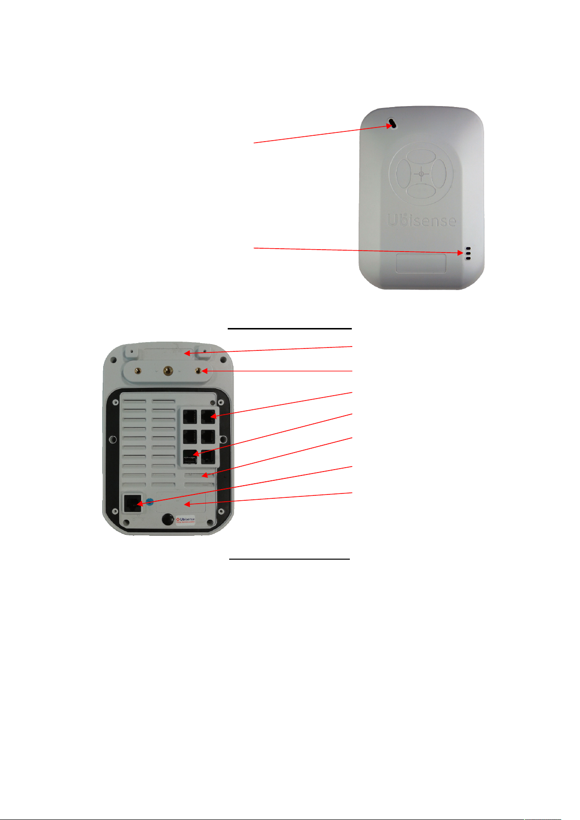
Features of the Ubisensor
Network Activity LEDs
The diagrams below show several important features of the Ubisensor:
Status LED
Figure 1 – Ubisensor Front
Space for regulatory information
Mounting holes
Timing cable sockets (x5)
USB expansion socket
Ventilation slots
Networking socket
(also provides PoE power)
Space for MAC address (ID) label
Figure 2 – Ubisensor Rear
Ubisense – Ultra-wideband Location System – Ubisensor30v1
Page 6
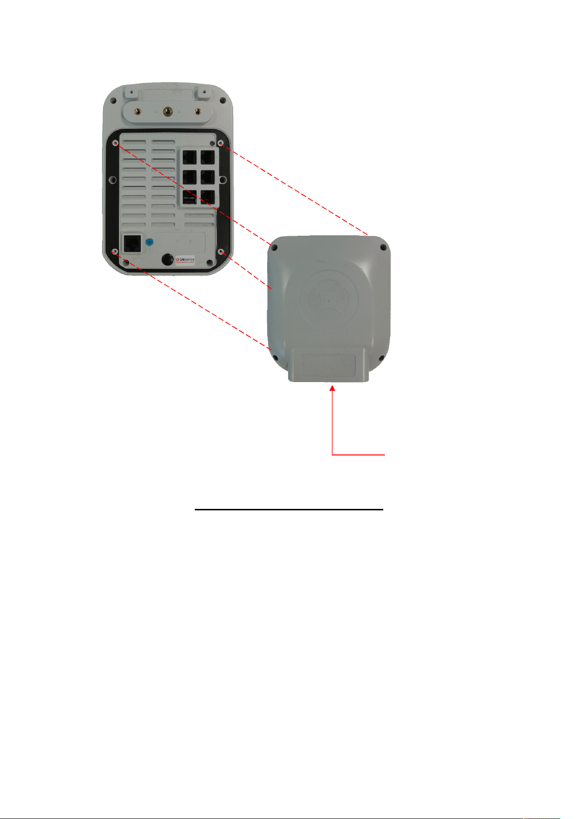
Optional dust cover
(attaches with four screws)
Figure 3 – Ubisensor optional dust cover
The optional rear dust cover may be used for installations where the sensor needs additional
protection from the environment. The cover may be fitted with suitable cable glands where the
cables exit from the cover on the bottom surface.
Cable entry at bottom of cover
Ubisense – Ultra-wideband Location System – Ubisensor30v1
Page 7

Installation and Operation Instructions
Mounting options
Ubisensors have three mounting holes in the back of the case, to which external clamps and
brackets can be attached. The two outer holes are M4 size, the middle hole is M6 size (and
can be used in conjunction with a standard photographic camera mount).
Powering the Ubisensors
Ubisensors must be powered using Power over Ethernet (PoE). This is normally done by
connecting the sensors to the network using a PoE switch. However, it is also possible to use
mid-span injectors if desired.
Setting up a sensor group
Ubisense will have supplied you with an updated location system database containing
configuration information for the equipment you have received. At this point, it’s worth
checking that the MAC (Media Access Control) addresses of the Ubisensors you have
received match the information in the database, using the Ubisense location system
configuration tools. See the software manual for details on how to examine the contents of the
configuration database – the MAC address for each Ubisensor is printed on a label affixed to
the rear of the unit (see “Features of the Ubisensor”).
Once you are sure you have the correct equipment to hand, the sensor cells for the system
can be set up. In the Ubisense location system, a large area of space is covered by a number
of sensor groups, each of which (individually) covers a smaller area.
Each sensor group has a number of units which are synchronized together using a timing
signal conveyed between the units by timing cables. The cables interconnecting the units are
unshielded Category 5e cable (or better).
Each sensor group has one sensor which is configured as a Timing Source. The remaining
sensors are configured not to be Timing Sources.
A timing cable from the Timing Source to other sensors can be plugged into any free timing
socket on the Timing Source, but must be plugged into the bottom left-hand timing socket
(Marked “5”) on the other sensors.
All sensors are connected to the standard network using a Category 5 unshielded cable (or
better). Power is supplied over the network cabling using Power over Ethernet (PoE)
techniques, so the sensors must be connected to the network via a PoE switch (or
alternatively to a non-PoE switch via mid-span PoE injectors).
The final wiring interconnection diagram for a three-member sensor cell would be as follows:
Ubisense – Ultra-wideband Location System – Ubisensor30v1
Page 8
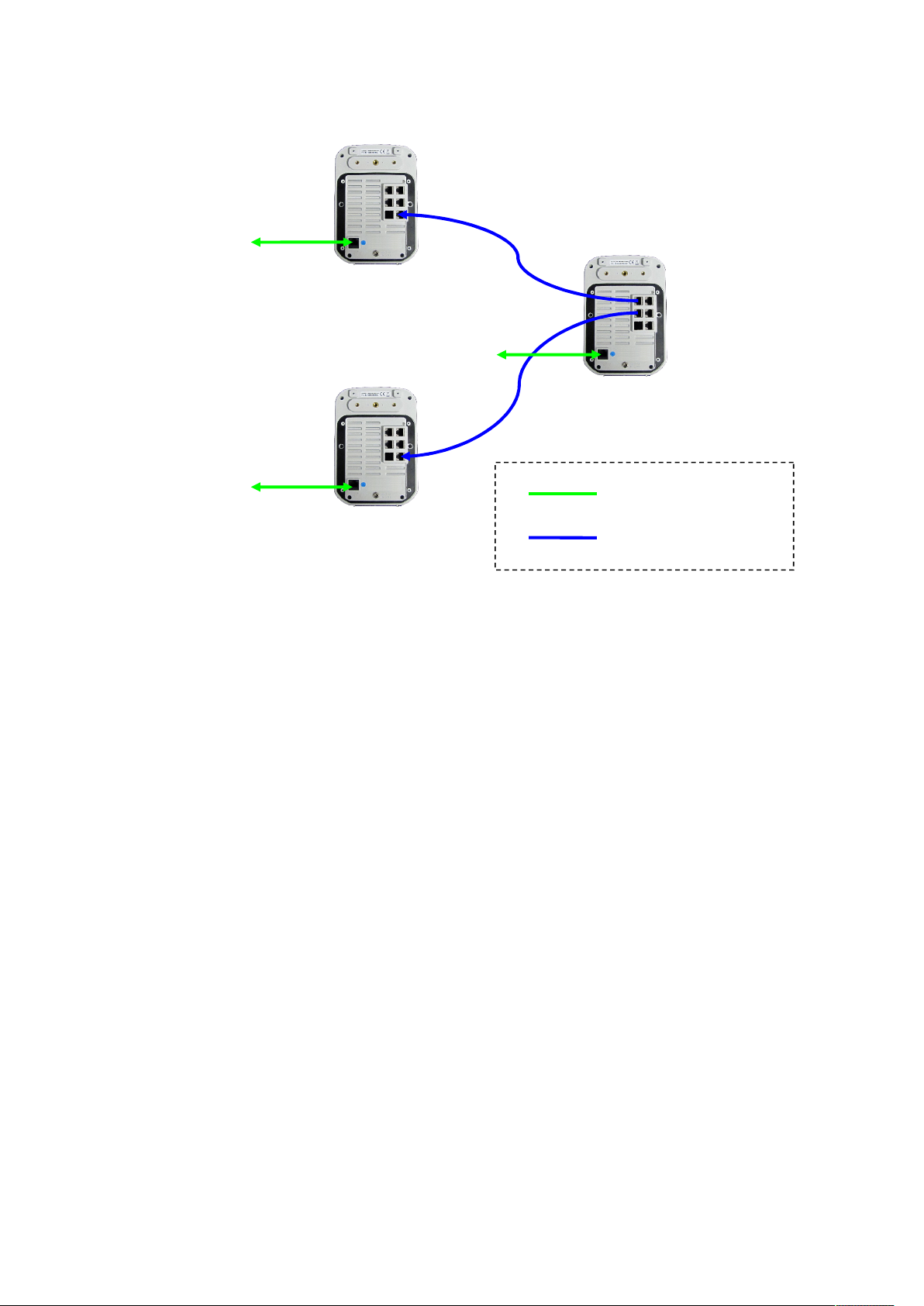
SOURCE
To
network
TIMING
To
network
To
network
Cat. 5 unshielded (or better)
Cat. 5e unshielded (or better)
Switching on the Ubisensor
To turn on a Ubisensor, simply turn on the power to the device. The Status LED on the front
of the Ubisensor should illuminate, and the device will begin to attempt to contact the
Ubisense location system (which should already have been installed on your network – see
the software manual for details). Configuration of the Ubisensor is entirely automatic, and is
under the control of the Ubisense location system.
Calibrating the Ubisensor
When the Ubisensor has been installed in its final location, its position and orientation must
be found and entered into the Ubisense location system’s database. The Ubisense location
system management tools make this calibration process simple and quick – refer to the
software manual for details.
Troubleshooting
If you believe that a Ubisensor is not functioning correctly, and the Ubisense location system
management tools are not able to diagnose the problem, it is likely that the Ubisensor is not
communicating with the rest of the location system for some reason. Check the following:
The networking cable is fully plugged in at both ends.
The Ubisensor is connected to a network connection which is providing PoE power.
Your local network port is connected to the rest of your network.
The link light corresponding to the Ubisensor network connection is illuminated on the
nearest upstream switch.
If you are still unable to determine the cause of the problem, contact your system installer or
Ubisense.
Ubisense – Ultra-wideband Location System – Ubisensor30v1
Page 9

Ubisensor Specifications
Conventional radio transceiver section (FCC ID: SEASENSOR30, IC: 8673A-SENSOR30)
Lowest channel frequency: 2401.750MHz (802.15.4f-2012 channel 15)
Highest channel frequency: 2481.750MHz (802.15.4f-2012 channel 56)
Maximum output power: +9dBm
General specifications
Dimensions: 200mm x 140mm x 60mm
Power supply: 48V PoE
Operating temperature range: -40ºC to +70ºC
Ubisense – Ultra-wideband Location System – Ubisensor30v1
 Loading...