

Carrier Class
AirMax BaseStation
Models: M3/M365/M5

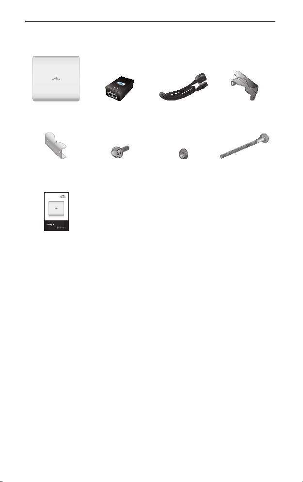
Package Contents
Package Contents
PowerBridge 24V PoE Adapter Power Cord Antenna Bracket
Pole Bracket
Clamps (Qty. 2)
Carrier Class
AirMax BaseStation
Models: M3/M365/M5
Quick Start Guide
Serrated Flange
Bolts (Qty. 4)
Serrated Flange
Lock Nuts (Qty. 4)
Clamps (Qty. 2)
M8X135 Carriage
Bolts (Qty. 4)
Installation Requirements
• Adjustable wrench or one 16 mm and one 24 mm wrench
• Flathead screwdriver
• Shielded Category 5 (or above) cabling should be used for all
wired Ethernet connections and should be grounded through
the AC ground of the PoE.
We recommend that you protect your networks from the
most brutal environments and devastating ESD attacks
with industrial‑grade shielded Ethernet cable from Ubiquiti
Networks. For more details, visit www.ubnt.com/toughcable
1
PowerBridge
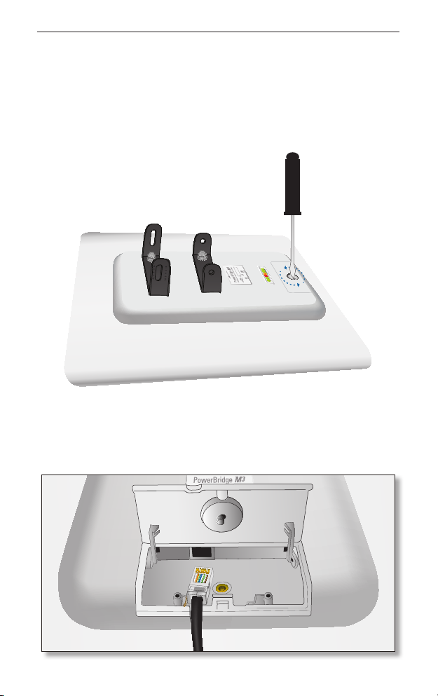
Hardware Installation
To install the PowerBridge, perform the following steps:
1. Use a flathead screwdriver to unlock the PowerBridge case.
Turn the screw counter‑clockwise until it is loose. The screw
remains attached to the compartment.
Compliant
RoHS
2. Lift the cover on the PowerBridge by pressing down and raising
it up. Connect an Ethernet cable. There is an opening for the
Ethernet cable. Slide the cover over the cable and secure it with
the screw.
2
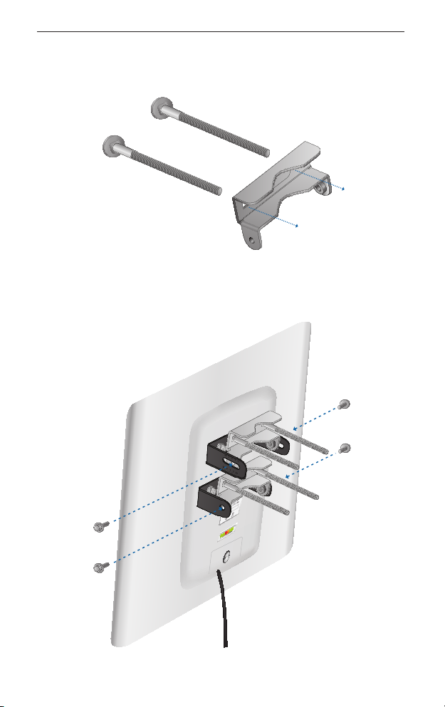
Hardware Installation
3. Insert the M8X135 Carriage Bolts into the Antenna Bracket
Clamps.
4. Connect the Antenna Bracket Clamps to the PowerBridge using
the four Serrated Flange Bolts.
RoHS
Compliant
3
 Loading...