

Ubiquiti AirOS User Manual
MANUAL AirOS

Contents
•
1 AirOS Introduction
•
2 Configuration Guide
o
2.1 Navigation
o
2.2 Main Page
2.2.1 Status Reporting
2.2.2 Statistics Reporting
2.2.3 Extra info
2.2.4 Tools
2.2.5 Antenna Alignment
o
2.3 Link Setup Page
2.3.1 Basic Wireless Settings
2.3.2 Wireless Security
o
2.4 Network
2.4.1 Bridge Mode
2.4.2 Router Mode
o
2.5 Advanced
2.5.1 Advanced Wireless Setting
2.5.2 Acknowledgement Timeout
2.5.3 Antenna Settings
2.5.4 Antenna Alignment LED Thresholds
2.5.5 Wireless Traffic Shaping
2.5.6 QoS
o
2.6 Services
2.6.1 Ping WatchDog
2.6.2 SNMP Agent
2.6.3 NTP Client, Web Server, Telnet Server
o
2.7 System
2.7.1 Administrative Management
2.7.2 Router Protocol Host Name
2.7.3 Logo Customization
2.7.4 UI Language Selection
2.7.5 Firmware
2.7.6 Configuration Management
2.7.7 Device Maintenance

AirOS Introduction
The design goal of AirOS was simplicity and power. Unlike previous and current
market-leading wireless or router operating systems that are complex and require a
training investment, Ubiquiti set out to make an advanced operating system capable of
powerful wireless and routing features, but was built upon a simple, clean, intuitive
user interface foundation.
Our goal is to make AirOS simple enough for the operator, customer, or new technician
to easily understand, configure, and deploy. At the same time, it is rapidly evolving
towards a path of new powerful networking and wireless features strongly derived
from customer interaction and feedback. Our goal is to make AirOs both the most
advanced operating system on the market and the most intuitive, easy to deploy.
Configuration Guide
This guide presents the detailed description of the AirOS operating system which is
integrated into long-range embedded systems (LiteStation2, LiteStation5), CPE
(NanoStation2, NanoStation5), and outdoor wireless platforms (PowerStation2,
PowerStation5) manufactured by Ubiquiti Networks, Inc.
AirOS Quick Setup Guide describes the configuration steps for the subscriber station
(wireless client - bridge) use case.
All the configuration settings accessible via web management interface are described in
this document.
IEEE 802.11b/g
•
NanoStation2
•
LiteStation2
•
PowerStation2
mode is supported in
IEEE 802.11a
•
•
•
mode is supported in
NanoStation5
LiteStation5
PowerStation5
All the devices support the following operating modes:
•
Station (Client)
•
Station WDS
•
Access Point
•
Access Point WDS / Repeater
All the devices support the following network modes:
•
Transparent bridge
•
Router

Note: the screen shots in this document represent PowerStation2 graphical user
interface but they are also fully applicable for NanoStation2 and LiteStation2 series
devices. The graphical user interface elements which are specific for the NanoStation5,
LiteStation5 and PowerStation5 are described individually in the this document.
Navigation
Configuration Management Menu
Each of the web management pages (listed below) contain parameters that affect a
specific aspect of the device:
Main page displays current status of the device and the statistical information. There
are useful network administration and monitoring tools available in Main page also (i.e.
speed test utility, site survey functionality in AP mode).
Link Setup page contains the controls for a wireless network configuration, while
covering basic wireless settings which define device operating modes, associating
details, data security options.
Network page covers the configuration network operating modes, IP settings, packet
filtering routines and network services (i.e. DHCP Server).
Advanced page settings are dedicated for more precise wireless interface control. It
also includes antenna polarity, traffic shaping and QoS settings.
Services page covers the configuration of system management services (i.e. SNMP,
NTP, Ping Watchdog).
System page contains controls for system maintenance routines, administrator
account management, device customization and configuration backup.
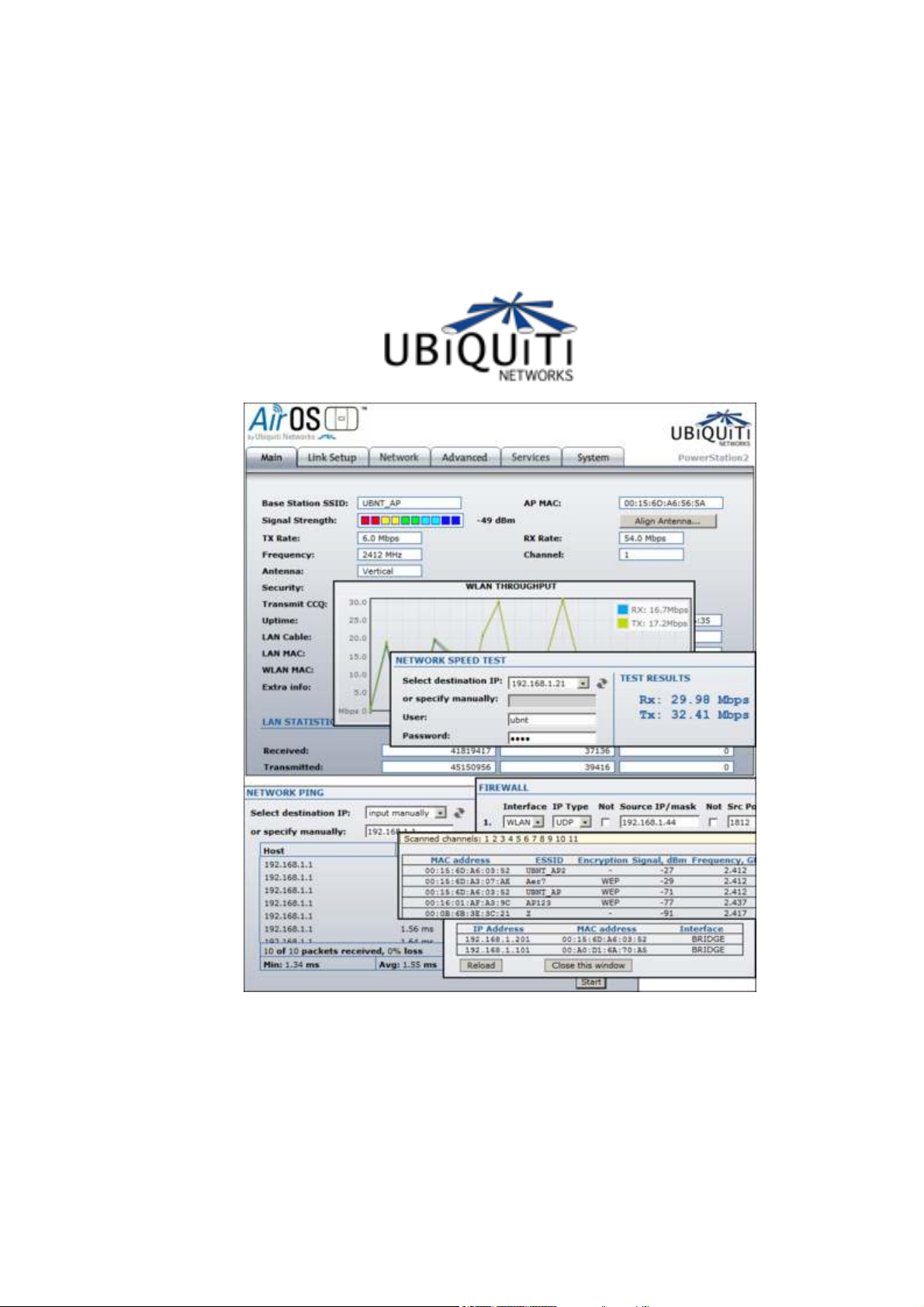
Main Page
Current Status of the AirOS powered device

The Main Page displays a summary of link status information, basic configuration
settings of the device (operating mode, network settings), traffic statistics of all the
interfaces.
Network administration and monitoring utilities such as antenna alignment, ping test,
and speed test tools are accessible via
Status Reporting
Base Station SSID: The Name of the 802.11 Service Set (established by the Host
Access Point) the device is connected to:
While operating in Station mode, displays the BSSID of the Access Point where
the device has associated.
While operating in in Access Point mode, displays the BSSID of the wireless
device itself.
AP MAC: displays the MAC address of the Access Point where the device has
associated while operating in Station mode. MAC (Media Access Control) is unique HW
identifier on each 802.11 radio. It consists of two parts:
An Organizationally Unique Identifier (OUI)
Network Interface Controller (NIC) sequence.
Main
page also.
The manufacturer list of a given MAC address is provided here:
http://standards.ieee.org/regauth/oui/index.shtml
Signal Strength: displays the received wireless signal level (client-side) while
operating in Station mode. The represented value coincides with the graphical bar. Use
antenna alignment tool to adjust the device antenna to get better link with the wireless
device. The antenna of the wireless client has to be adjusted to get the maximum
signal strength. Signal Strength is measured in dBm (the Decibels referenced to 1
miliwatt). The conversion is defined as dBm=10log10(P/1mW). So, 0dBm would be
1mW and –72dBm would be .0000006mW. A signal strength of –85dBm or better is
recommended for stable links.
Antenna Alignment: This is a utility which allows the user to optimize the antenna
direction for maximum link signal. More information is provided in the
section.
TX Rate and RX Rate: displays the current 802.11 data transmission (TX) and data
reception (RX) rate while operating in
(802.11b) and 6,9,12,18,24,36,48,54Mbps (802.11) are possible. Typically, the higher
the signal, the higher the data rate, and consequently the higher the throughput. For
maximum throughput (54Mbps), typically a –70dBm or better signal is required.
Station
mode. Data rates at 1,2,5.5,11Mbps
Tools
sub-
Frequency: This is the operating frequency of the 802.11 Service Set (hosted by AP)
the client is connected to. Device uses this frequency to transmit and receive data. For
802.11a operation, the range of available frequencies are 5.1-5.9Ghz and for
802.11b/g operation, 2412-2472Mhz. However, the specific frequencies that can be
used will vary depending on local country regulations. For more information, please
visit the
compliance section of Ubiquiti Wiki.

Channel: This is the 802.11 channel number that corresponds to the operating
frequency. Device uses the selected channel to transmit and receive data. More
information is provided in the
Antenna: This shows which antenna option the AirOS device is using currently. Most
of Ubiquiti Devices have 4 antenna options: vertical, horizontal, and Adaptive Antenna
Polarity (AAP) options. There is also often an external antenna option.
Link Setup
section.
Security: This is the current security setting. More information is provided in the
section.
Setup
ACK Timeout: displays the current ACK Timeout value, which is set on the device
manually or adjusted automatically. The ACK Timeout (Acknowledgement Timeout)
specifies how long the AirOS device should wait for an acknowledgement from partner
device confirming packet reception before concluding the packet must have been in
error and requires resending. ACK Timeout is very important outdoor wireless
performance parameter. More information is provided in the
Transmit CCQ: This is an index which assesses the connection quality of the link. It
takes into account transmit errors, latency, and throughput while evaluating the ratio
of successfully transmitted packets against the re-transmitted ones and taking into
account current rate ratio against the highest specified rate. The level is based on a
percentage value where 100% corresponds to a perfect link state.
QoS Status: displays the current QoS setting. Quality of Service (QoS) can be enabled
to direct link speeds to better service particular customers and/or particular
applications like VoIP and video which require greater consistency, stability, and lower
latency performance.
Uptime: This is the running total of time the device has been running since last power
up (hard-reboot) or software upgrade. The time is expressed in days, hours, minutes
and seconds.
Advanced
settings section.
Link
Date: indicates the current system date and time, expressed in the form “year-monthday hours:minutes:seconds”. System date and time can be retrieved from the internet
services using NTP (Network Time Protocol).
LAN cable: displays the current status of the Ethernet port connection. This can alert
operator/user/technician that LAN cable is plugged into device and there is an active
Ethernet connection.
Host Name: displays the customizable name (ID) of the device as it will appear in
popular Router Operating Systems registration screens.
LAN MAC: displays the MAC address of the AirOS device LAN (Ethernet) interface.
LAN IP Address: displays the current IP address of the LAN (Ethernet) interface.
WLAN MAC: displays the MAC address of the AirOS device WLAN (Wireless) interface.
WLAN IP Address: displays the current
IP address of the WLAN (Wireless) interface.

Note:
address of the virtual
LAN IP Address
and
bridge
Statistics Reporting
LAN interface Statistics
WLAN IP Address
interface, while the device is operating in
displays the same value - current IP
Bridge
mode.
LAN Statistics: section displays the detailed receive and transmit statistics (
Packets, Errors
of data and packets transfered between devices through the ethernet interface either
way.
Both unicast IP traffic (conversations between two hosts using HTTP, SMTP, SSH and
other protocols) and broadcast traffic (while addressing all hosts in a given network
range with a single destination IP address) is accounted.
As long as there is some network traffic being generated or passed through the
interface, Received and Transmitted
Errors
value represents the total number of transmitted and received packets for which
an error occurred.
WLAN interface Statistics
WLAN Statistics: section displays the detailed receive and transmit statistics (
Packets, Errors
) of
LAN
) of the
(Ethernet) interface. This statistics represents the total amount
Bytes
and
wireless
Packets
interface.
value will go on increasing.
Bytes
LAN
Bytes
,
,
This statistics represents the total amount of unicast and broadcast IP data transfered
between devices through the
As long as there is some network traffic being generated or passed through the
'
wireless
will go on increasing.
PPP interface Statistics
PPP Statistics: section displays the IP address of the
receive and transmit statistics (
statistics are available in
interface, Received and Transmitted Bytes, Packets and Errors (if any) value
wireless
Router
interface either way.
Bytes, Packets, Errors
mode only, while
PPPoE
PPP
interface and the detailed
) of the
PPP
interface. PPP
is enabled.

This statistics represents the total amount of unicast and broadcast IP data transfered
between AirOS powered device and PPPoE server through the
PPP
tunnel either way.
As long as there is some network traffic being passed through the
Received and Transmitted Bytes, Packets and Errors (if any) value will go on
increasing.
Refer to the
WLAN Errors Statistics
WLAN Errors: section displays the counters of 802.11 specific errors which were
registered on
Network
wireless
Rx invalid NWID value represents the number of packets received with a
different NWID or ESSID - packets which were destined for another access
point. It can help to detect configuration problems or identify the adjacent
wireless network existence on the same frequency.
Rx Invalid Crypt value represents the number of transmitted and received
packets which were encrypted with the wrong encryption key and filed the
decryption routines. It can be used to detect invalid
Rx Invalid Frag value represents the number of packets missed during
transmission and reception. These packets were dropped due to re-assembling
failure as some link layer fragments of the packet were lost
Tx Excessive Retries value represents the number of packets which failed to
be delivered to the destination. Undelivered packet are retransmitted a number
of times before an error occurs.
Missed beacons value represents the number beacons (management packets
sent at regular intervals by the Access Point) which were missed by the client.
This indicates that the client is out of range.
Other errors value represents the total number of transmitted and received
packets that were lost or discarded for other reasons.
section for more information aboutPPPoEsetup.
interface:
wireless security
PPP
tunnel,
settings.
The content of the
Main
page can be updated by using the Refresh button.
Extra info
Extra Info: displays the current device usage statistics and status of the system
components in pop-up window:
Status of the Associated Stations

•
Show Stations: selection lists the stations which are connected to the device
while operating in Access Point mode.
Statistics for all the stations (RSSI, Tx Rate, Rx Rate and Idle time) can be
updated using the Reload button.
More statistics (Station Uptime, Negotiated Rates, Static WDS Flag,
Tx/Rx Frames, Tx/Rx Bytes) can be retrieved while clicking on the “+”
button near MAC address of the each Station entry.
Current Status of the system ARP table
•
Show ARP Table: selection lists all the entries of the ARP (Address Resolution
Protocol) table currently recorded on the device.
The list can be updated using the Reload button.
ARP is used to associate each IP address to the unique hardware address
(MAC) the devices. It is important to have unique IP addresses for each MAC or
else there will be ambiguous routes in the network.
Current Status of the system routing tables
•
Show Routes: selection lists all the entries in the system routing table, while
the device is operating in Router mode.
The list can be updated using the Reload button.
AirOS examines the
destination IP address
through the system and chooses the appropriate interface to forward the
packet to. The system choice depends on static routing rules – entries, which
are registered in system routing table. Static routes to specific hosts, networks
or default gateway are set up automatically according to the IP configuration of
all the AirOS interfaces.
AirOS IP configuration description is provided in the
of each data packet traveling
Link Setup
section.

Current Status of the system bridge table
•
Show Bridge Table: selection lists all the entries in the system bridge table,
while the device is operating in
The list can be updated using the Reload button.
Bridge table shows to which
in other words from which
(defined by
packets to that port only (thus saving a lot of redundant copies and transmits).
Ageing timer
particular time out, not having seen a packet coming from a certain address,
the bridge will delete that address from the Bridge Table.
MAC address
shows ageing time for each address entry (in seconds) - after
) is reachable to AirOS system while forwarding the
Bridge
bridge
interface
mode.
port the particular station is associated to -
(ethernet or wireless ) the network device
Status of the throughput on LAN interface
•
Show Throughput selection continuously represents the current data traffic
on the LAN, WLAN and PPP interfaces in both graphical and numerical form.
The statistics is updated automatically and can be updated using the Reload
button.
 Loading...