

Page 1

OPERATOR’S MANUAL
FOR FRONT END LOADER (TX2000)
Page 2

WARRANTY CONDITIONS
TYM Tractor Division, herein referred to as TYM, undertakes to replace or repair any part of a TYM loader where damage has be
en
g
gp
TYM s liability under this warranty is subject to the observance by the Purchaser of the following provisions:
g
gg pp,,, p ,gg,,
g
Warranty Coverage :
proven to be caused by defects in material or workmanship.
This Warranty is valid for a period of 1 year from the date of the original retail sale. Parts replaced or repaired under the terms of this
Warranty are guaranteed only until the original warranty expires. Warranty only applies to the original purchaser.
It is further understood and agreed that the defect should be immediately reported to the Selling Dealer. The Selling Dealer will
generally perform Warranty repairs or replacements and the Purchaser shall deliver the TYM Loader to the Dealer's place of business
or repair.
The obligation of TYM to the Purchaser under this Warranty is limited to the repair or replacement of defective parts by an authorized
TYM dealer. Repair or replacement in accordance with this Warranty shall constitute fulfillment of all liabilities of TYM and the
Dealer in respect to TYM Loaders.
Sellin
There are no warranties beyond those which expressly appear herein. Any implied warranty of merchantability or fitness for a
particular purpose is specifically exclude here from.
Warranty Provisions :
'
The purchaser shall at all times in the operation of any TYM Product, use those brands and grades of lubricating oils, lubricants or fuel
and spare parts officially approved by TYM.
The TYM Loaders shall have been used in accordance with the procedures specified in the Operator's Manual. This Warranty does not
extend to dama
or faulty mounting carried out by the Purchaser. When making a Warranty exchange of parts, the Purchaser shall compensate TYM for
the time that the parts have been used if they have been exposed to extreme wear.
Compensation is not paid for physical harm, deadlock, resulting damages or other losses.
To obtain warranty service, the Purchaser must (1) report the product defect to an authorized TYM dealer and request repair within the
applicable warranty term and (2) present evidence of purchase.
The Warranty shall be void if the TYM Loader has been altered or repaired outside of a TYM dealership or travel of dealer personnel
to customer location for Warranty repair. The customer shall also pay any premium for overtime labor requested by the customer.
e resulting from misapplication, abuse, misuse, failure to preform maintenance, negligence, fire, accidents orchanges
- 2 -
Page 3

Temporary repairs or additional costs due to the work being performed after normal working hours will not be compensated.
y
ypyyy
The above warrant
TYM's Products.
is in lieu of all other warranties on TYM's behalf and neither party assumes any other liability in connection with
Right To Make Design and Product Changes :
TYM reserves the right to make changes in the design and other changes in its TYM Products at any time without incurring any
obligation with respect to any product previously ordered, sold or shipped.
- 3 -
Page 4

TABLE OF CONTENTS
BUCKET
36
POST ASSEMBLY
44
LOADER INSTALLATION
52
SAFETY –1 --------------------------------------------------------------- 5
SAFETY -2 ----------------------------------------------------------------
SAFETY DECALS -------------------------------------------------------
LOADER SPECIFICATION --------------------------------------------
INTRODUCTION --------------------------------------------------------
TRACTOR PREPARATION -------------------------- -----------------
LOADER OPERATION -------------------------- ----------------------
LOADER REMOVAL ---------------------------------------------------
LOADER MOUNTING --------------------------------------------------
LUBRICATION AND MAINTENANCE -----------------------------
TROUBLE SHOOTING -------------------------------------------------
METRIC FASTENER(ISO)TORQUE CHART ----------------------
PART ILLUSTRATIONS -----------------------------------------------
-------------------------------------------------------------------
QUICK ATTACHMENT ASSEMBLY --------------------------------
MOUNTING FRAME ASSEMBLY------------------------------------
BOOM ASSEMBLY -----------------------------------------------------
-------------------------------------------------------
STAND & SAFETY BAR ----------------------------------------------
HYDRAULIC PIPING ASSEMBLY ----------------------------------
DECAL ---------------------------------------------------------------------
-------------------------------------------
FRONT END LOADER HISTORY CARD --------------------------
6
7
8
9
18
20
25
26
27
29
33
35
38
40
42
46
48
50
56
- 4 -
Page 5

SAFETY
y
aware of the stability and load characteristics of this loader before you
y, , ,
d b
ibili
St
lifti
Understand that your safety and the safety of other persons is
measured by how you service and operate this loader. Know the
position and operations of all controls before you to operate.
Make sure you check all controls in all safe area before starting.
The safety information given in this manual does not replace any
Codes, insurance needs, federal, state and local laws.
safet
Make sure your Machine has the correct equipment required by your
local laws and regulations.
SAFETY PRECAUTIONS
Read this manual completely and thoroughly and make sure you
understand all controls. All equipment has a limit. Make sure you are
begin operation.
This safety alert symbol indicates important safety messages in this
manual.
When you see this symbol, carefully read the message that follows
e alert to the poss
an
ty of personal injury or death.
-Before starting the engine of your tractor, make sure all operation
controls are in park lock or neutral position.
-Operate controls only when seated in the operator’s seat.
-Equip your tractor with a ROPS cab or frame for your protection.
-See your tractor operator’s manual for correct seat belt usage.
-A frequent cause of personal injury or death is persons falling off
and being run over.
-Do not permit others to ride on your tractor. Only one person, the
operator, should be on the machine when it is in operation.
-Before leaving the tractor, stop the engine, put all controls in
neutral, engage the parking brake and remove the key from the
ignition.
-When using remote hydraulic tractor valves on some tractors, the
loader lift and dump cylinders will continue moving unless the
control levers are manually returned to neutral, or until relief
pressure is reached at the ends of piston strokes.
-Observe the bucket movement and maintain control with the
control levers.
op the loader arms gradually when lowering or
-
-Stay off of slopes too steep for safe operation.
-Shift down before you start up or down a hill with a heavy load.
-Avoid “free wheeling”
-Travel speed should be such that complete control and machine
stability is maintained at all times. Where possible, avoid operation
near ditches,embankments and holes.
-Reduce speed when turning, crossing slopes, and on rough, slick or
muddy surfaces.
-Never use your hand to check for suspected leaks under pressure.
-Use a piece of cardboard or wood for this purpose. Escaping
hydraulic oil or diesel fuel leaking under pressure can have
sufficient force to penetrate the skin and cause infection or other
injured by leaking fluid, seek medical attention immediately.
-To prevent personal injury, relieve all pressure before disconnecting
fluid lines.
-Before applying hydraulic pressure, make sure all hydraulic
connections are tight and components are in good condition.
- 5 -
ng loads.
Page 6

SAFETY
H
is securely blocked or held in position. Accidental movement of a control
,
surface with all safety devices engaged to prevent loader from falling
,,
iti
ith bucket
-Contact with overhead power lines can cause severe electrical burn
or death from electrocution. Make sure there is enough clearance
between raised equipment and overhead power lines.
-Add recommended rear tire liquid weight or rear wheel weights for
increased stability.
-A loader attachment should be transported in a low position at slow
ground speeds.
-Make turns slowly and use the tractor brakes cautiously.
WARNING SIGNS IN THIS MANUAL
The following warning signs in this manual draw additional
attention to items of importance for the safe and correct operation
of the tractor.
SIGN MEANING OF THE SIGN
Serious hazard with a very high level of
risk of either serious injury or death
DANGER
-A loaded attachment in the raised position alters the center of
gravity location of the machine and increases the possibility of mishaps.
-Do not stand, walk or work under a raised loader or attachment unless it
lever of leak in the hydraulic system could cause the loader to drop, or
attachment to dump, causing severe injury.
-Make sure all parked loaders on stands are on stands are on a hard level
and being damaged or injuring someone.
-When using a loader, be alert of bucket position at all times.
-Loader in raised pos
tractor causing damage or injury to tractor and / or operator.
-Always park loader with bucket attached to loader.
on w
rolled back can dump material on
azard or unsafe practice that can lead
to severe injury or death.
WARNING
CAUTION
Hazard or unsafe practice that can lead
in injury or death.
Instructions for the correct operation of
IMPORTANT
the machine which
ensure that it performs at it’s best
if followed, will
All information,illustrations and specifications in this
manual are based on latest information available at the
time of publication.The right is reserved to make changes
at any time without notice.
- 6 -
Page 7

SAFETY DECALS
Care of Safety Decals
-Safety Decal Locations
-
1. Keep safety decals clean and free of obstructing material.
2.Clean safety decals with safety decal (s) affixed is replaced with
a soft cloth.
3. If a component with a safety decal (s) affixed is replaced with a
new part, make sure new safety decal (s) are attached in the same
location (s) as the replaced components.
4. Mount new safety decals by applying on a clean dry surface and
pressing air bubbles to outside edges.
.
- 7 -
Page 8

LOADER SPECIFICATION
B
Maxi
lift height
t
2100
82.7 "
N
Length of Attachment (to pivot pin)
513 mm
20.2
B
2.4
Loader Total Weight (1+2+3) 328kg 723 lb
1 Weight of Boom & Quick Atta. 169kg 373 lb
2 Weight of Mounting Frame 67kg 148 lb
3 Weight of Bucket 92kg 203 lb
Boom raising time 4.2sec
oom lowering time
Bucket rollback time 3.3sec
Bucket dumping time 4.7sec
sec
A Maximum lift height to pivot pin 2235 mm 88 "
mum
under lever bucke
mm
C Clearance with bucket dumped 1717 mm 67.6 "
D Reach at maximum lift height 604 mm 23.8 "
E Maximum dump angle 47
¶ 47 
F Reach with bucket on ground 1485 mm 58.5"
G Maximum rollback angle 33
¶ 33 
H Digging depth 114 mm 4.5 "
J Overall height in carry position 1160 mm 45.7 "
L Depth of Attachment (to back of inner shell) 464 mm 18.3 "
M Height of Attachment 513 mm 20.2 "
Lift capacity to maximum height at pivot pin 626kgf 1380 lbs
Breakout force at ground level, pivot pin 934kgf 2059 lbs
Bucket rollback force at ground line 724kgf 1596 lbs
Relief valve setting (Loader control valve) 160kg/cm
2
2276psi
Rated Flow (Tractor System) 18.9 L/min 5 gpm
Lift Cylinder 45X30mm 1.8X1.2 "
Bucket Cylinder 50X30mm 2.0X1.2 "
Bucket Width 1520mm 60 "
Bucket Capacity 0.137m
3
4.8ft
"
3
- 8 -
Page 9

INTRODUCTION
yy
dealer for further information
g
The i
gg
The purpose of this manual is to assist you in maintaining and
operating your loader. Read it carefully, it furnishes information and
instructions that will help you achieve years of dependable
performance. Some information may be general in nature due to
unknown and varying conditions. However, through experience and
these instructions, you should be able to develop operating procedures
suitable to your particular situation.
“Right” and “Left” as used throughout this manual are determined by
facing the direction the machine will travel when in use.
The photos, illustrations and data used in this manual are current at the
time of printing, but due to possible in-line production changes, your
machine may vary slightly in detail.
The manufacturer reserves the ri
reserves the right to redesign the machine as may be necessary without
notification.
Loader Serial Number Information
Date purchased ____________________
Loader Serial Number ____________________
Dealer Name and Telephone Number ______________
ht to redesign the manufacturer
Important
-Illustrations used in this manual may not show all safety
equipment that is recommended to ensure safe operation of
tractor and loader. Refer to the Safety Precautions section of
this manual for information concerning safety. Consult your
.
Warranty Registration
The Delivery and Warranty Registration forms must be filled out
and signed to validate Your warranty protection.
tems on the form under “I hereby Acknowledge” should be
read and understood.
The terms and conditions of the warranty on this machine are
specified in the front of this manual.
Serial Number and Location
The serial number is important information about the machine and
it may be necessary to know it before obtaining the correct
replacement part. The serial number plate is located on the LH(left
hand) inside of front area of boom. The serial number should be
recorded on the Deliver and Registration form and also below for
your reference.
- 9 -
Page 10

FILLING THE BUCKET
d
Approach and enter the pile with a level bucket.Ease lever back and toward you to lift and rollback the bucket.
The lift and rollback of the bucket will increase efficiency because a level bucket throughout the lifting cycle
resists bucket lift and increases breakaway effort.
Note: Do not be concerned if the bucket is not completely filled during each pass Maximum productivity is
etermined by the amount of material loaded in a given period of time.Time is lost if two or more attempts are
made to fill the bucket on each pass
- 10 -
Page 11

LIFTING THE LOADER
WARNING
j
bucket
ity l
ill
Do not lift or carry anyone in the bucket or on any
other position of the loader or loader attachment.
Inadvertent movement of the loader or attachment
could result in serious Injury or Death from falling or
crushing.
CAUTION
Make sure material in bucket cannot rollout and down
on tractor when bucket is raised to full height .Keep
clear of overhead obstructions such as trees,limbs or
power lines when raising the bucket.
When lifting the load,Keep the bucket positioned to
avoid spillage.
CARRYING THE LOAD
Position the bucket just below the level of the tractor
hood for maximum stability and visibility,whether the
bucket is loaded or empty.
Use extreme caution when operating the loader on a
slope,Keep the bucket as low as possible ,this keeps the
and tractor center of grav
provide maximum tractor stability.
ow and w
- 11 -
Page 12

CAUTION
p
pppg, p
DUMPING THE BUCKET
Operating the loader on a hillside is dangerous.
Extreme care is recommended.
When transporting the load,Keep the bucket as low as
ossible to avoid tipping,in case a wheel drops in a rut.
Lift the bucket high enough to clear the side of the
vehicle.
Move the tractor in as close to the side of the vehicle
as possible,then dump the bucket
- 12 -
Page 13

LOWERING THE BUCKET
hile l
lling back the bucket
Exercise caution when under cutting high Banks.Dirt
After the bucket is dumped,back away from the vehicle
w
owering and ro
OPERATING WITH FLOAT CONTROL
During hard surface operation,Keep the bucket level and
put the lift control in the float position to permit the
bucket to float on the working surface.If hydraulic down
pressure is exerted on the bucket,It will wear faster than
normal.
The float will also prevent the mixing of surface
material with stockpile material.The float position will
reduce the chance of surface gouging when removing
snow or other material.
LOADING FROM A BANK
slides can be dangerous.Load from as low as possible
for maximum efficiency.Loader lift and breakaway
capacity diminish as loading height is increased
- 13 -
Page 14

Side cutting is a good technique for cutting down a
big pile
cut over the top
gouging
Another method for large dirt piles is to build a ramp
approach to the pile.
If the pile sides are too high and liable to cause cave-in,
Use the loader to break down the sides until a slot can be
.
It is important to keep the bucket level when
approaching a bank or pile. This will help to prevent
the work area
- 14 -
Page 15

PEELING AND SCRAPING
hil
Thi
ill all
cleanly
LOADING LOW TRUCKS OR SPREADERS
p
py g
Use a slight bucket angle,travel forward,and hold
the lift control forward to start the cut.Make a short,
angle cut approximately 6” deep and break out
.
With the bucket level,start a cut at the notch
approximately 2” deep.
Make additional passes until the desired depth is
reached.During each pass,only use the bucket control
w
e at working depth.
concentrate on controlling the bucket angle to
maintain a precise cut.
s w
ow you to
FROM A PILE
Hold the de
adjust the cutting lip up or down.When the front tires
enter the notch,adjust the lift to maintain proper
depth.
th by feathering the bucket control to
For faster loading,minimize the angle of turn and
length of run between pile and spreader
- 15 -
Page 16

BACK FILLING
g
gy
Backgrade occasionally with a loaded bucket to keep
the working surface free of ruts and holes.Hold the
lift control forward in FLOAT POSITION so the full
weight of the bucket is scraping the ground.Use only
the heel of the bucket while backgrading.
IMPORTANT: To prevent damage to Cylinders:
(1) Do not back
(2) Always backgrade with valve in float position.
rade with bucket cylinders extended.
Poor methods actually move no more dirt and make it
more difficult to hold a level grade.
Do not use the bucket in the dumped position for
bulldozing or backgrading.This method,shown
above,will impose severe shock loadings on the dump
linkage,the bucket Cylinder,and the Tractor.
Approach the pile with a flat bucket
Leave dirt in the bucket because dumping on each
pass wastes time.
- 16 -
Page 17

Operate at right angles to the ditch,Take as big as
the tractor can handle without lugging down.
and oil drums.
Leave dirt which drifts over the side of the bucket for
final clean-up
Pile dirt on the high side for easier backfilling on a slope
HANDLE LARGE HEAVY OBJECTS
WARNING
Do not Use front end loaders for handling large,heavy
objects such as large,Round or rectangular bales,logs
Handling large heavy objects can be extremely
dangerous due to:
•Possibility of rolling the tractor over.
•Possibility of upending the Tractor.
•Possibility of the object rolling or sliding down the
loader arms onto the operator.
- 17 -
Page 18

TRACTOR PREPARATION
TRACTOR TIRES
from contacting the ground across its full width
Rear Counterweight
Caution
-Add recommended rear tire liquid weight, rear wheel or
rear ballast for increased stability.
Caution
-Do not exceed the manufacturer’s rating for maximum
gross vehicle weight.
-Refer to Operator’s Manual or ROPS serial plate provided
with tractor.
-The use of adequate counterweight to counter balance for
maximum loader capacity is required for safe loader
operation.
-Weight added to rear of the tractor provides better traction
and easier, more efficient loader operation, The tractor
can be counter weighted by filling rear tires with liquid
calcium solution and/or by the installation of rear wheel
weights.
-Additional counterweight requirements will vary with
loader attachments and equipment applications.
-Additional weight can be added by installation of Three
Point Hitch mounted ballast.
Caution
The tractor/loader must only be operated with all safety
equipment properly installed.
-Selection of tires(size, profile, tread type) should be
restricted to tire recommendations as specified by TYM
Tire Inflation
-Front tires must be maintained at the maximum
recommended inflation to Maintain normal tire profile
with the added weight of loader/material.
-Rear tires must be maintained at equal pressure within
the recommended tire inflation range.
-Unequal rear tire inflation can prevent loader attachment
.
- 18 -
Page 19

Caution
pyp
Tractor front wheel tread setting must be restricted to
recommendations on counterweight tractor
S
Refer to your tractor Operator s Manual maintenance
Manual concerning hydraulic fluid and filter
-Certain specific conditions may not permit safe use of
loader at loader rating or may require more careful
restricted operation at the rated load.
-Refer to Tractor Operator’s Manual for specific
.
ROPS System
-The tractor must be equipped with an approved ROPS
ystem to ensure adequate operator’s protection.
Tractor Hydraulic System
-Tractor operation in a loader application significantly
increase demands on the tractor Hydraulic System.
-Check the tractor Hydraulic system fluid level daily.
-
’
section for instructions regarding tractor hydraulic
system maintenance.
-Adhere to recommendation in your Tractor Operator’s
specifications, and change intervals.
Wheel Tread Settings
-
wheel tread spacing recommended in the tractor
Operator’s Manual.
Front Counterweight
-Use of front counterweight is not recommended when
tractor is being used in a loader application.
Front counterweight adds unnecessary front axle load in
loader applications.
- 19 -
Page 20

LOADER OPERATION
Th
1.Read
thi
r
K
ith th
your attention in this manual, the tractor manual and on
y
bucket cylinders partially extended
y
cylinders) during backfilling/back grading operations
Position vehicle to be loaded as near the pile as possible
-
Keep the unit clean and perform regular service. Observe
Caution
e tractor/loader should only be operated with all safety
equipment properly installed.
Precautionary Notes
Do not lower the edge of the bucket too low for loading.
eep the bottom of the bucket level w
loading.
Important
Do not use the bucket for pushing down material with
.
Damage to the cylinders may result.
Important
Do not tip bucket cutting edge down(fully extended bucket
Important
-Operation with front tractor wheels off the ground is not
recommended.
and in such a direction as to minimize the amount of
tractor turning required to dump.
-Do not lower the loader with the tractor engine shut off.
e ground when
.
We urge you to follow this advice:
and understand
Operator’s Manual.
2.Remember and observe the Safety Precautions brought to
the machinery itself.
3.Use good common sense in the everyday operation of this
unit. Safet
and you are responsible for watching out for and avoiding
unsafe conditions.
4.Never exceed the limits of a piece of machinery. If its
ability to do a job or to do so safely is in question, don’t
try it.
5. Don’t hurry the learning process or hake the unit for
granted. Ease into it and become familiar with your new
loader and tractor.
recommendations can never be all-inclusive
s manual as well as the Tracto
safety messages
-whenever cleaning, servicing, or lubricating.
- 20 -
Page 21

Caution
When lowering a heavy load, ease it downward slowly
Bef
jured by escaping hydraulic oil, see
l
ju ed by escap g yd au c o , see ed ca
the hoses are damaged
Slowly cycle the lift and bucket cylinders several times to
.
Never drop a loaded attachment and “catch it
hydraulically” Stopping a load after it has gained
downward momentum places undue strain on the unit and
may cause unnecessary damage to the loader or tractor or
Even worse, personal injury.
Caution
Before disconnecting hydraulic lines, relieve all
hydraulic pressure.
Escaping hydraulic oil under pressure can have sufficient
force to penetrate the skin causing serious personal injury.
If in
k medical
Attention immediately.
Caution
Do not operate the loader if the fittings are leaking or if
.
A sudden line burst would cause the mainframe to drop
suddenly, causing damage to the tractor or loader or
injury to personnel.
Initial Loader Operation
ore operating the loader fully raise and lower the boom
two or three time. Then raise the bucket approximately
four(4) feet above the ground and cycle the bucket to the
ground.
Check the tractor hydraulic oil and the correct oil level.
Caution
Before leaving the machine, stop the engine, remove the key,
ace all controls in neutral, and either set the parking brake
p
or place tractor in park as equipped.
Always keep cylinders in a retracted position when the loader
is not in use to guard against rust and contamination which
may cause damage to the cylinder rods or hydraulic system.
Cold Weather Operation
For smooth operation in cold weather, let the tractor warm up.
warm the oil in the hydraulic system. The loader may
operate erratically until the hydraulic oil has warmed to
operating temperatures.
- 21 -
Page 22

LOADER OPERATION
g
When using a loader, be aware of bucket location at all
operator
St
lifti
Caution
Operate controls only when seated in the operator’s seat
Loading Bucket
For the most efficient loading, slowly drive the tractor
straight into the material to be loaded and increase speed
only after contact has been made. Roll the attachment back
a small amount and slowly lift to break away the material.
As the load increase, continue rolling the attachment back
so as to get the maximum load.
Remove the top levels first when loading from large piles
of material When bucket is full, raise loader so the bucket
is clear of material and slowly back out of the pile.
Dumping Bucket
When in the dump area slowly drive the tractor forward
and raise the loader at the same time.
Raise the loader to the height needed to dump the bucket.
Make sure to keep a level bucket position to prevent
spilling from the bucket. Dump the bucket, and keep all
movements smooth.
Transporting a Loaded Bucket
Transport material with the bucket as low as possible to
prevent spilling and keep maximum stability. The loader
must be in a position that will not block the operators’
vision. a loaded Bucket must not be transported in the
upright position or at excessive speed.
Observe the following safety warning when transporting a
loaded bucket.
Caution
times.
When raising a loader with bucket rolled back, material can
dump onto tractor causing damage to tractor of injury to
.
Caution
Contact with overhead power lines can cause severe
electrical burns or death from electrocution.
Make sure there is clearance between raised equipment and
over head power lines.
Caution
op the loader arms gradually when lowering or
ng.
- 22 -
Page 23

Caution
ggg,p
gravity location of the machine and increases the
b
valve body and regulates flow of oil to/from cylinders.
gy
A loaded Bucket should be transported in a low position at
low ground speeds.
Make turns slowly and use the tractor brakes cautiously.
A full bucket in the raised position alters the center of
possibility of accidents.
Caution
Do not stand, walk or work under a raised loader unless it
is securely blocked or held in position.
Accidental movement of a control lever or leak in
hydraulic system could cause the loader to drop, or
attachment to dump, resulting in serious injury or death.
Scraping
When scraping, the Boom lever must be used to keep the
ucket on the ground horizontally.
The bucket must be kept level to the ground during
scraping operations.
Backfilling/Back grading
When “Backfilling” of “Back grading”, position the
bucket so it is level on the ground.
Do not dump material from bucket following each pass.
As additional weight of material in
bucket will assist in “Back grading” and increases loader
efficiency during “ backfilling”
Controlled Rate of Loader Functions
By “feathering” the control lever, reduced operational
speeds can be controlled.
This action controls the position of the valve spool in the
It is important to utilize this operational practice when
lowering loader boom when the bucket is loaded with
material.
- 23 -
Page 24
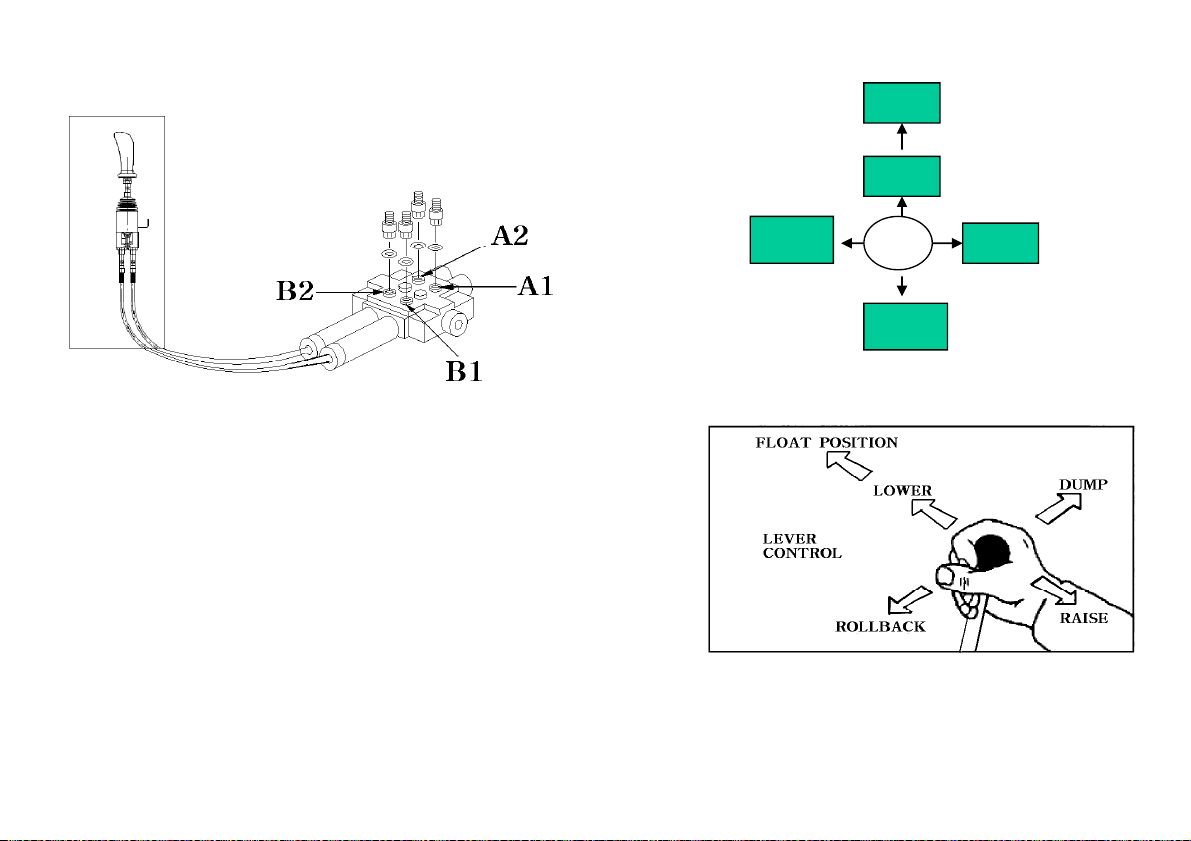
LOADER OPERATION
N
BACK
DUMP
Loader Hydraulic Controls
The single lever and joystick control lever is mounts on the tractor from the factory.
The control lever has the safety lock function.
Lock the control level when leaving the tractor while the Bucket is in the air.
The loader hydraulic valve lift Cylinder circuit incorporates a “FLOAT” position
which allows the loader bucket to follow ground contours. The “FLOAT” position is
engaged by shifting the control lever forward into “Detent” until the operator pulls the
control lever out of the “Detent” position.
Refer to “Scraping” operation for recommended use of “FLOAT” position.
The control valve has a neutral position that prevents movement of loader or bucket.
When the control valve is released from the work position, the spool will return to neural.
FLOAT
LOWER
ROLL
RAISE
Important :
Contaminates in hydraulic oil can cause valve spools to stick. Be alert when operating
loader and follow your Tractor Operator’s Manual maintenance schedule.
- 24 -
Page 25
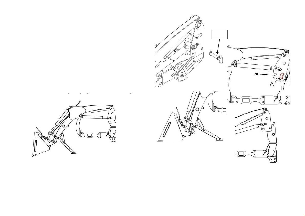
LOADER REMONAL
Caution
PIN
STEP 2.
pgg g
STEP 6
STEP 8
Caution
Never park loader without bucket attached the loader.
Never allow weight of tractor to be put on parking leg when
removing loader
STEP 1.
Park the tractor and loader on hard level surface.
Raise the boom until the bucket is about 2 feet off the ground.
STEP 3.
Set the parking legs with pivot pin and keeper.
STEP 4.
Lower the boom until the parking legs make contact on the ground.
Tip the bucket until the bucket cutting edge touch the ground.
STEP 5.
Remove the latch pin while move the control lever back and forth
Slightly to make the latch pin easy.
.
Control the boom cylinder to come out “A” from “B”.
Rollback the bucket until column come out from Mounting bracket.
STEP 7.
Move the tractor rearward slowly and stop to avoid the Hydraulic
hoses being tighten.
.
Right several times to reduce the hydraulic pressure in the Hoses.
STEP 9. Disconnect the quick couplers on the hydraulic hoses.
- 25 -
Page 26
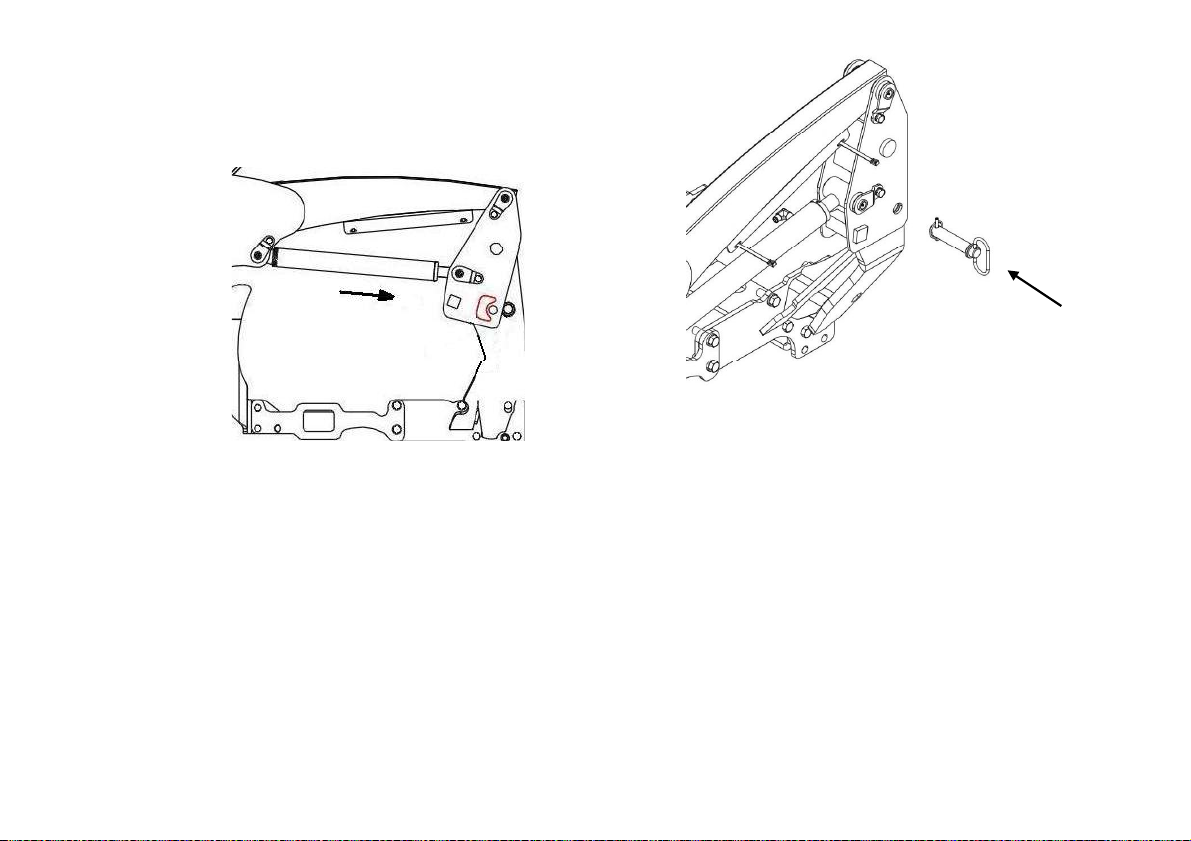
LOADER MOUNTING
Carefully drive the tractor into the loader to a position where the
right several times to reduce the pressure in the hydraulic Hoses
the post
Caution
Never allow weight of tractor to be put on parking when
mounting loader.
STEP 1.
Hydraulic hoses (Quick coupler) can be connected to the control Valve
block.
STEP 2.
Stop the engine and move the control lever back and forth, Left and
Connect the hydraulic couplers match the color code rings.
STEP 3.
Start the engine and move the boom and bucket to adjust the height of
.
Be sure to check the Hook of inner mounting frame is slightly
Higher than the pin welded on mounting frame.
STEP 4.
Move the tractor forward to put into the inner mounting frame.
Stop the tractor When the hook is right over the pin.
Lower the inner mounting frame with moving the boom and bucket
until it hooked securely each other
STEP 5.
.
Align the latch pin holes with moving the bucket and boom. insert the
latch pins.
Rubber hammer can be used to put the pin in if needed.
STEP 6.
Remove pin and keeper holding the parking legs and return.
To storage position, Make secure by using pin and keeper.
- 26 -
Page 27

LUBRICATION AND MAINTENANCE
Operate the loader from the tractor seat only
to drop, causing severe injury
Note
E
ffici
Grease all loader pivot points daily (10 hours).
Serious infection or reaction can develop if correct medical treatment
p
pgg
Caution
Do not perform and service or maintenance Operations with loader
raised off the ground.
For additional access to tractor components remove loader.
Important
Lower the loader to the ground and relieve pressure in loader
hydraulic lines prior to performing any service or maintenance
operations on the tractor or loader.
Caution
scaping fluid under pressure can have su
the skin, causing serious injury. Before disconnecting lines, be sure to
relieve all pressure.
Before applying pressure to the system, be sure all connections are
tight and that lines, pipes and hoses are not damaged. Fluid escaping
from a very small hole can be almost invisible.
Use a piece of cardboard or wood rather than your hands to search for
suspected leaks.
If injured by escaping fluid, seek medical attention immediately.
is not administered immediately.Refer to Lubrication and maintenance
Chart” for quick reference to Maintenance Operations.
Caution
Do not o
damaged.
A sudden line burst could cause the mainframe to drop suddenly,
causing damage to the tractor or loader or injury to personnel.
erate the loader if the fittings are leaking or if the hoses are
ent force to penetrate
Caution
.
Caution
Do net stand or walk under a raised loader. Accidental movement
of control lever or leak in hydraulic system could cause mainframe
.
Check the tractor hydraulic system as outlined in the Tractor
operator’s Manual.
When checking hydraulic system oil level, the loader should be on
the ground and bucket fully retracted
(all cylinders in retracted position.)
Refer to Tractor Operator’s Manual for lubricant recommendations.
Inspect hydraulic hoses, connections, control valve and cylinders
for evidence of leakage.
Tractor tires should be maintained at maximum recommended
inflation to maintain normal tire profile with added weight of
loader/material. Unequal rear tire inflation can result in bucket not
being level to the ground.
- 27 -
Page 28
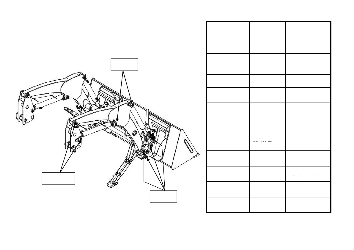
LUBRICATION AND MAINTENANCE
Loader hydraulic
packingservice as
if
a y/ 0 ou s
Grease
ITEM SERVICE
Hydraulic system
oil level
Hydraulic system
oil/Filter
Tire Inflation Check Weekly/50 hours
Check Daily10 hours
Replace
SERVICE
INTERVAL
As specified in
Tractor Operator’s
Manual
Grease
Grease
- 28 -
Loader pivot
points
lines, hoses
Connections
Lift and bucket
cylinder rod
Pivot bolts and
dust covers
Mid-mount latch
and lynch pins
Loader mount
hardware
Loader mount
hardware
Lubricate Daily/10 hours
Check for
leaks, wear
Check for
seepage,
needed
Check, replace
if missing
Check, replace
necessary
Check visually Daily/10 hours
Retighten Every 25 hours
Daily/10 hours
Daily/10 hours
Daily/10 hours
Dil1 hr
Page 29
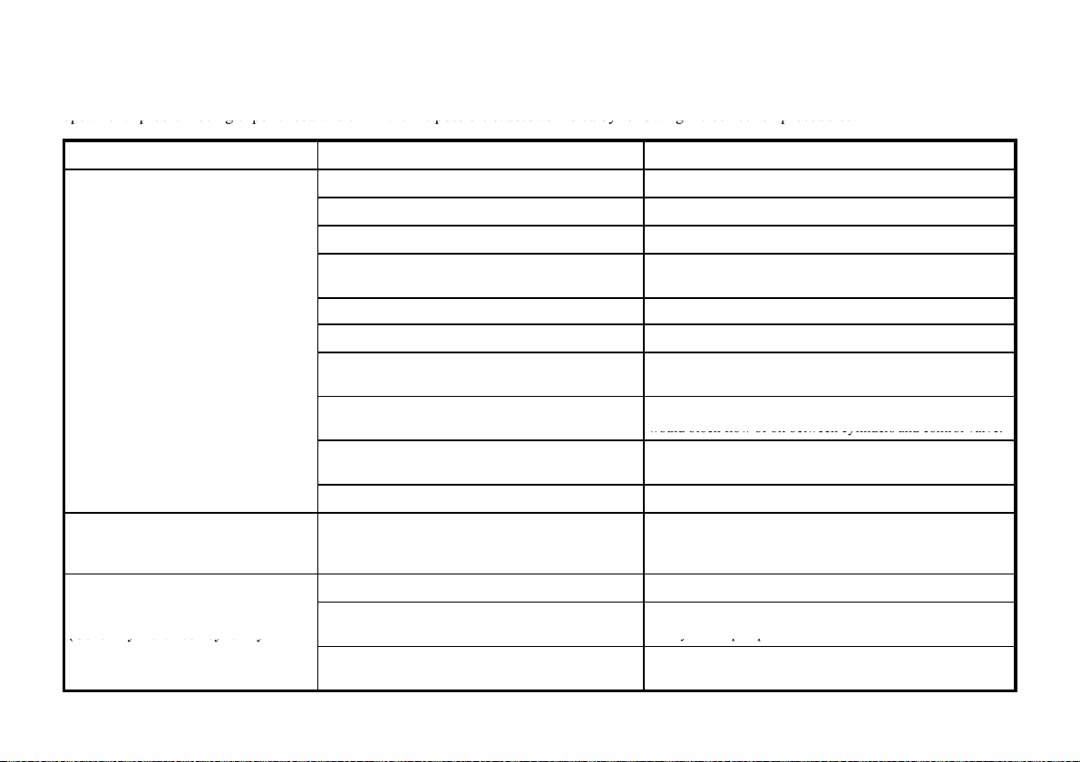
TROUBLE SHOOTING
operational problem being experienced and e
ate the possible causes as
sted by following the correction procedures.
operational problem being experienced and eliminate the possible causes as Listed by following the correction procedures.
would block flow of oil between cylinders and control valve.
y
(Generally indicated
foamy
ypp
This Trouble Shooting Chart is provided for reference to possible loader operational problems.Determine the problem that best describes the
PROBLEM POSSIBLE CAUSE CORRECTION
Loader Lift slow and/or will not Dump
limin
Low hydraulic fluid level. Check and replenish hydraulic fluid.
Hydraulic hoses connected improperly. Check and correct hydraulic hose connections.
Hydraulic hoses to/from control valve blocked Check for damage (kinked) hoses,etc.
Loader control valve or tractor main relief valve stuck
open
Low system pressure supplied from hydraulic pump. Check system pressure. Repair or replace pump.
Control valve linkage broken. Inspect. Repair as required.
Quick disconnect coupler(s)are not fully connected or
“Flow Check”
Hydraulic hose or tube line blockage.
Li
Check system pressure. Repair or replace relief valve.
Check coupler connections. Replace coupler(s) unnecessary.
Check for evidence of damage to hoses or tube lines that
Check cylinders for internal leakage as described in service
section under cylinder leakage tests.
Check for loose or defective connections between reservoir
and h
draulic pump.
Left to Tractor Operator’s Manual and replace hydraulic oil
using recommended hydraulic oil.
Lift and/or Bucket Cylinders operate
in wrong direction relative to control
valve level position.
Aeration of Hydraulic Fluid
appearance of fluid)
by
Cylinder piston assembly defective(not sealing)
Control valve blockage. Inspect for blockage. Disassemble valve if necessary.
Hydraulic hoses connected incorrectly Correct hydraulic hose connections.
Low hydraulic fluid level. Check and refill hydraulic system to proper level.
Air leaking into suction side of hydraulic pump
Hydraulic fluid foaming due to improper hydraulic oil
usage.
- 29 -
Page 30
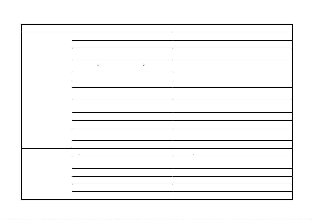
TROUBLE SHOOTING
g
gg
Red
Check coupler connections. Repair or replace
Relief valve erratic or set below specifications
Check and reset relief valve. Setting as needed
g
g
g
PROBLEM POSSIBLE CAUSE CORRECTION
Low hydraulic fluid level. Check and replenish hydraulic fluid.
Cold hydraulic fluid. Allow hydraulic system to warm up to operating temperature.
Engine RPM too slow (hydraulic pump RPM too slow). Increase engine speed to obtain satisfactory loader operation.
Slow or erratic lift
Inadequate lifting
capacity
Excessive wei
maximum specified loader capacity.
Control valve linkage binding/defective Check control valve linkage and repair if worn/defective.
Aeration of hydraulic fluid Refer to “Aeration of Hydraulic Fluid”
Quick disconnect coupler restriction or coupler “Flow
checks”
Hydraulic hose or tube line restriction (hose/tube line)
kinked or pinched.
Lift cylinder piston assembly leakage. Check cylinders for leakage. Repair as needed.
Control valve leaking internally. (bypassing fluid within
valve)
Inadequate hydraulic pump capacity. Refer to “Hydraulic Pump Capacity Inadequate”
ine RPM too slow. Increase engine RPM
En
Excessive load-material weight exceeds specified loader
capacity.
Relief valve setting below specifications. Check and reset relief valve setting as needed.
Lift cylinder piston assembly leakage Check cylinders for leakage. Repair as needed.
Control valve leaking internally. Replace control valve and recheck operation.
Hydraulic pump defective. Refer to “Hydraulic Pump Capacity Inadequate”
ht in bucket. Material weight exceeds
.
uce material load.
.
Check hoses and tube lines for evidence of restriction.
.
Replace control valve and recheck operation.
Reduce load.
- 30 -
Page 31
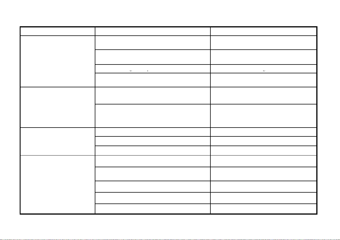
TROUBLE SHOOTING
g
d
gp
g
external oil leakage evident.)
PROBLEM POSSIBLE CAUSE CORRECTION
System relief valve squeals.
Loader drops with control valve
spool in “centered” position (no
Cold Hydraulic Fluid.
Excessive load in bucket.
Weight exceeds specified loader capacity.
Relief valve settin
Hydraulic hose, tube line or quick disconnect coupler
restriction.
Cylinder piston assembly leakage. Check cylinder for leakage.
below specifications. Check and reset valve setting as neede
Allow hydraulic fluid to warm up to operating
temperature.
Reduce load.
Check for evidence of restriction in hydraulic oil flow.
Repair or replace defective components.
Note:A gradual drop over an
extended period of time is a
normal condition.
Control valve spool(s) will not
return to centered position.
External hydraulic fluid leakage.
Control valve internal leakage. Replace control valve and recheck.
Control lever linkage binding. Determine origin of binding and repair.
Control valve spool centering is broken. Replace centering spring.
Control valve spool binding in valve body spool bore. Disassemble valve for inspection and repair
Loose hydraulic connection. Tighten loose connections.
Defective hydraulic hose, tubeline, adapter fitting or adapter
fitting O-ring.
Control valve O-rings defective. Replace defective O-rings
Control valve spool or body damaged or worn. Replace control valve.
Cylinder rod packing set leakage. Check cylinders for leakage. Repair as needed.
Check for origin of oil leak and replace defective part.
- 31 -
Page 32

TROUBLE SHOOTING
Ref
p
p
practices
Bucket cutting edge wear rate is
Incorrect operational practices.
Refer to operation
scraping section for correct operating
accelerate wear rate of bucket
Bucket wear pads worn
Replace wear pads
PROBLEM POSSIBLE CAUSE CORRECTION
Hydraulic pump capacity
Inadequate.
Lift cylinder rod bend when lift
cylinders extended.
Bucket cutting edge wear is uneven
side to side
excessive.(Wear rate is even across
full width of bucket).
Note:Extensive use of bucket on
concrete or asphalt surfaces will
cutting edge.
Cold hydraulic fluid.
Engine RPM Too slow. Increase engine RPM
Low hydraulic fluid supply
Hydraulic hose restriction. Check for evidence of restriction in hydraulic hose.
Hydraulic pump defective.
Excessive shock load on lift cylinders during
transport.
Bucket is not level to ground.
Excessive down pressure placed on bucket when
being used on hard abrasive surfaces.
.
Allow hydraulic fluid to warm up to operating
temperature.
er to Tractor Operator’s Manual for service
recommendations.
Refer to Tractor O
service procedures.
Replace hydraulic pump if determined to be defective.
Replace defective parts.
Review and observe proper and safe operational
.
Check rear tire inflation and adjust to level bucket to
ground.
procedures.
Utilize float position.
erator’s Manual for recommend
-
.
- 32 -
Page 33
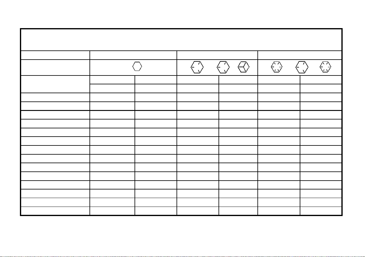
METRIC FASTENER(ISO) TORQUE CHART
Fasteners can be dry or lubricated with normal engine oil. Values do not apply if graphite. moly
disulphide or oth
er extreme pressure
Note: Use these torques. Unless special torques are specified. Values are for UNF thread fastener, plated or un-plated as received from supplier.
-
lubricant is used.
SAE Grade No. 2 5 8*
Bolt head identification
(see note 1)
Bolt size
1/4
5/16
3/8
7/16
1/2
9/16
5/8
3/4
7/8
1
1 1/8
1 1/4
1 3/8
1 1/2
LB FT NM LB FT NM LB FT NM
Min Max Min Max Min Max Min Max Min Max Min Max
5 6 7 8 9 11 12 15 12 15 16 20
10 12 14 16 17 20.5 23 28 24 29 33 39
20 23 27 31 35 42 48 57 45 54 61 73
30 35 41 47 54 64 73 80 70 84 95 114
45 52 61 70 80 96 109 130 110 132 149 179
65 75 88 102 110 132 149 179 160 192 217 260
95 105 129 142 150 180 203 244 220 264 298 358
150 185 203 251 270 324 366 439 380 456 515 618
160 200 217 271 400 480 542 651 600 720 814 976
250 300 339 406 580 696 787 944 900 1080 1220 1464
800 880 1085 1193 1280 1440 1736 1953
1120 1240 1519 1681 1820 2000 2468 2712
1460 1680 1980 2278 2380 2720 3227 3688
1940 2200 2631 2983 3160 3560 4285 4827
Note.1:Bolt head identification marks as per grade. Manufacturing marks will vary.
*Thick nuts must be used with Grade 8 bolt
- 33 -
Page 34
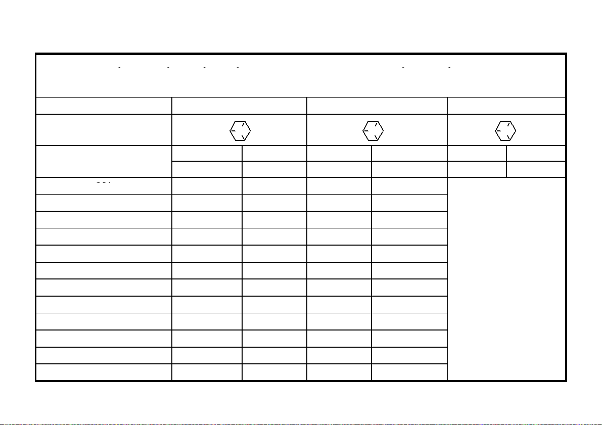
N
m
METRIC FASTENER(ISO) TORQUE CHART
qpqp ,p
p
Bolt head identification
M4
these fasteners, the torque
ranges specified for grade 10.9
M30
1250
1500
920
1100
2000
2400
1470
1770
ote: Use these torques. Unless special torques are specified. Values are for UNF thread fastener, plated or un-plated as received fro
supplier. Fasteners can be dry or lubricated with normal engine oil. Values do not apply if graphite. moly-disulphide or other extreme
pressure lubricant is used.
ISO Class No. 8.8 10.9 12.9
(see note 1)
Bolt size
M5
M6
M8
M10
M12
*M14
M16
M20
M24
M36
Note:Bolt head identification marks as per grade. Manufacturing mark will vary.
LB FT NM LB FT NM LB FT NM
Min Max Min Max Min Max Min Max Min Max Min Max
3 4 2 3 4 5 3 4
6.5 8 5 6 9.5 11 7 8
10.5 12 8 9 15 17.5 11 13
26 31 19 23 37 43 27 32
52 61 38 45 73 87 54 64
90 75 66 79 125 150 93 112
144 172 106 127 200 245 149 179
217 271 160 200 310 380 230 280
434 515 320 380 610 730 450 540
675 815 500 600 1050 1275 780 940
2175 2600 1600 1950 3500 4200 2580 3090
- 34 -
Because of the low ductility of
range is to be determined
individually for each
application.
As a general rule,the torque
fasteners can be used
satisfactorily on 12.9 fasteners
*M14 is not a preferred Size.
Page 35

PART ILLUSTRATIONS
GENERAL INFORMATION
The individual
Illustrati
Illustrations
parts in their normal relationship to each other. Reference numbers are used in the
numbers correspond to those in the “Number” column and are followed by the quantity required and description.
Directional Reference
“Right hand” and “left hand” sides are determined by standing at the rear of the unit and facing in the direction of
forward travel.
Part Order
Orders must give the complete description, correct part number, the total amount required, the product model, all the
necessary serial numbers, the method of shipment and the shipping address.
ons. These
- 35 -
Page 36
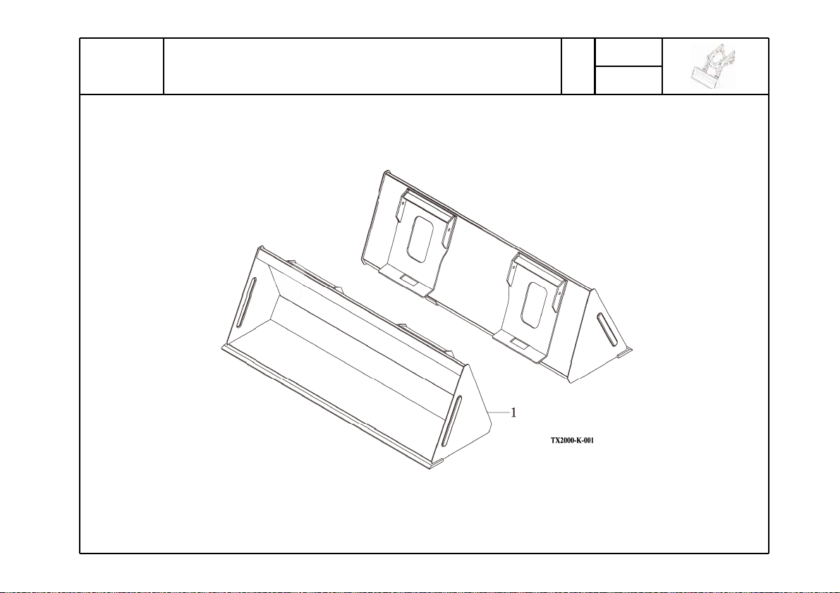
mpnGWWX
i|jrl{
TX2000
Year / Month
P1
2011 / 01
- 36 -
Page 37

ΊΖΒΣ;ΠΟΥΙ
mpnGWWX
ͳΆʹͼͶ΅
KEY NO.
001 001 BT28P BUCKET ASSY 1
PART NO. DESCRIPSTION SPEC. QTY. EFFECTIVE DATE REMARKS
- 37 -
Page 38
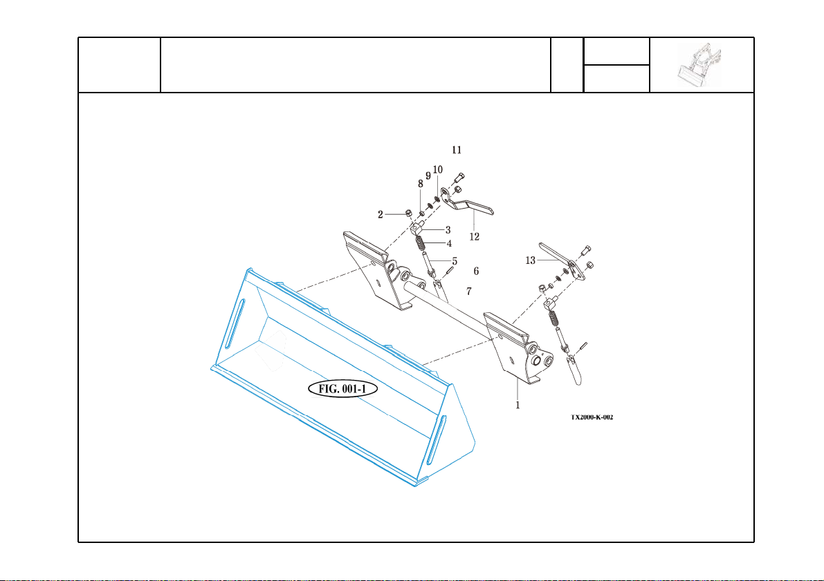
mpnGWWY
x|pjrGh{{hjotlu{GhzzN
TX2000
Year / Month
P1
2011 / 01
- 38 -
Page 39
ΊΖΒΣ;ΠΟΥΙ
mpnGWWY
ΆͺʹͼͲ΅΅Ͳʹ;ͶͿ΅Ͳ΄΄Ί
KEY NO.
002 001 B0800A2000 COUPLER 1
002 002 NL16200Z LOCK NUT M16 4
002 003 B0945A1210 PIN 30X30 2
002 004 B0945A1320 SPRING 2
002 005 B0945A1230 PIN
002 006 PS08040 SPRING PIN
002 007 B0945A1220 PIN
002 008 B0800A0010 BUSHING
002 009 WP16M PLAIN WASHER M16 2
002 010 WS16M SPRING WASHER M16 2
002 011 BH1677200Z BOLT(10.9T) M16X35L 2
002 012 B0800A1110 LEVER RH 8T 1
002 013 B0800A1120 LEVER LH 8T 1
PART NO. DESCRIPSTION SPEC. QTY. EFFECTIVE DATE REMARKS
Ժ30
ԺΉͽ
Ժ30
Ժ
2
2
2
2
- 39 -
Page 40
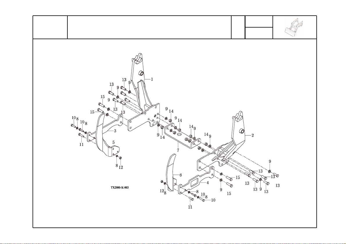
mpnGWWZ
tv|u{punGmyhtlGhzzN
TX2000
Year / Month
P1
2011 / 01
- 40 -
Page 41
ΊΖΒΣ;ΠΟΥΙ
mpnGWWZ
;ΆͿ΅ͺͿͷͲ;ͶͲ΄΄Ί
KEY NO.
003 001 T293A1100 SUB FRAME RH 1
003 002 T293A1200 SUB FRAME LH 1
003 003 T293A1310 BRACKET RH 12T 1
003 004 T293A1410 BRACKET LH 12T 1
003 005 T293A4110 BUMPER RH 12T 1
003 006 T293A4210 BUMPER LH 12T 1
003 007 T293A6110 UNDER BAR 12T 1
003 008 WS12M SPRING WASHER M12 6
003 009 WS16M SPRING WASHER M16 16
003 010 BH1288175Z BOLT(10.9T) M12X40L 4
003 011 BH12A6175Z BOLT(10.9T) M12X50L 2
003 012 NH12175Z NUT M12 2
003 013 BH1699200Z BOLT(10.9T) M16X45L 12
003 014 NH16200Z NUT M16 8
003 015 BH16B9200Z BOLT(10.9T) M16X55L 4
PART NO. DESCRIPSTION SPEC. QTY. EFFECTIVE DATE REMARKS
- 41 -
Page 42
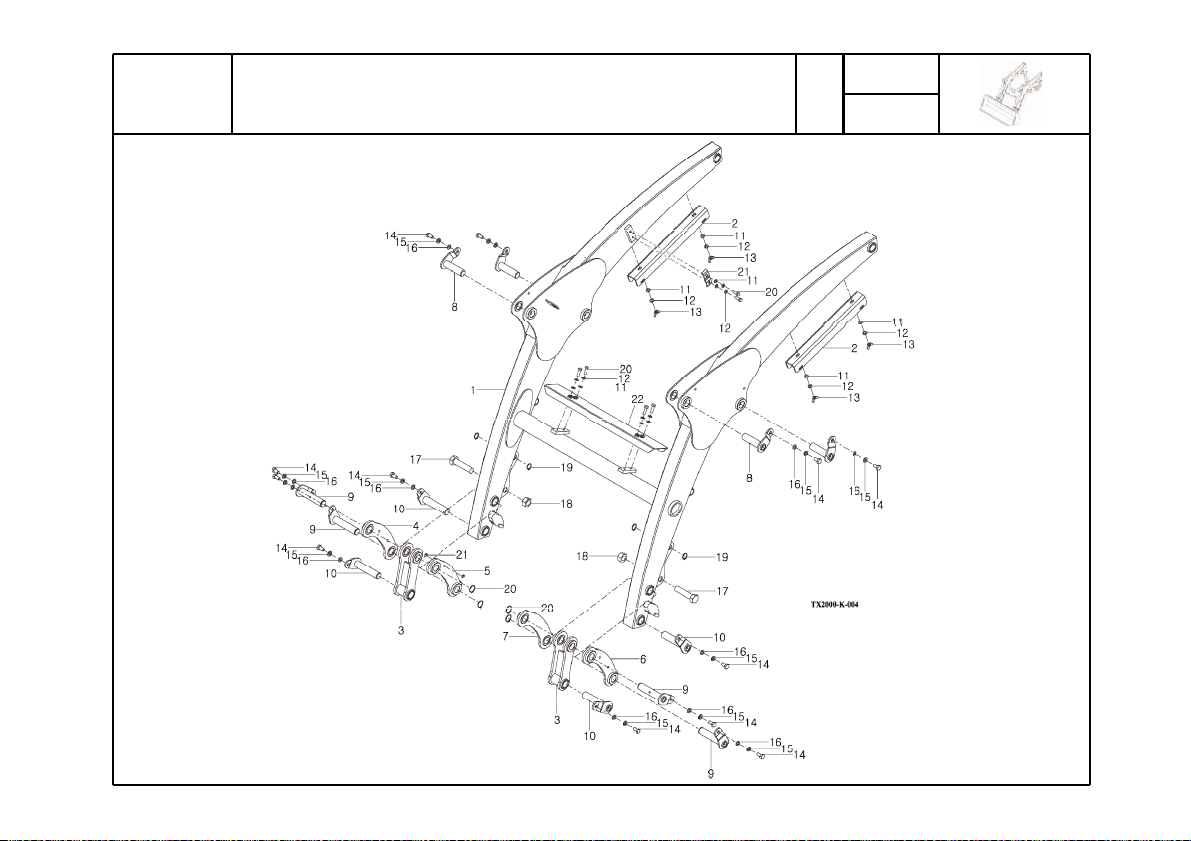
mpnGWW[
ivvtGhzzN
TX2000
Year / Month
P1
2011 / 01
- 42 -
Page 43
ΊΖΒΣ;ΠΟΥΙ
mpnGWW[
ͳ;Ͳ΄΄Ί
KEY NO.
004 001 C1600C-0000 BOOM ASSY 1
004 002 C1600C-0010 SAFETY BAR 4T 2
004 003 C1600C-4100 BUCKET ROD 2
004 004 C1600C-6100 LINK BRACKET,RH-OUT 1
004 005 C1600C-6200 LINK BRACKET,RH-INN 1
004 006 C1600C-7100 LINK BRACKET,LH-OUT 1
004 007 C1600C-7200 LINK BRACKET,LH-INN 1
004 008 P25A-090A PIN
004 009 P25S-115A PIN
004 010 P25A-115A PIN
004 011 WP08M PLAIN WASHER M8 10
004 012 WS08M SPRING WASHER M8 10
004 013 NB08125Z WING NUT M8 4
004 014 BH1044150Z BOLT(10.9T) M10X20L 12
004 015 WS10M SPRING WASHER M10 12
004 016 WP10M PLAIN WASHER M10 12
004 017 BH20H5250X BOLT(10.9T) M20X85L 2
004 018 NL20250Z LOCK NUT M20 2
004 019 SN20M SNAP RING
004 020 BH0855125X BOLT(10.9T) M8X25L 6
004 021 ALN47073100 COVER 4T 1
004 022 C1400B7010 COVER 2.3T 1
PART NO. DESCRIPSTION SPEC. QTY. EFFECTIVE DATE REMARKS
Ժ
Ժ
Ժ
Ժ
4
4
4
4
- 43 -
Page 44
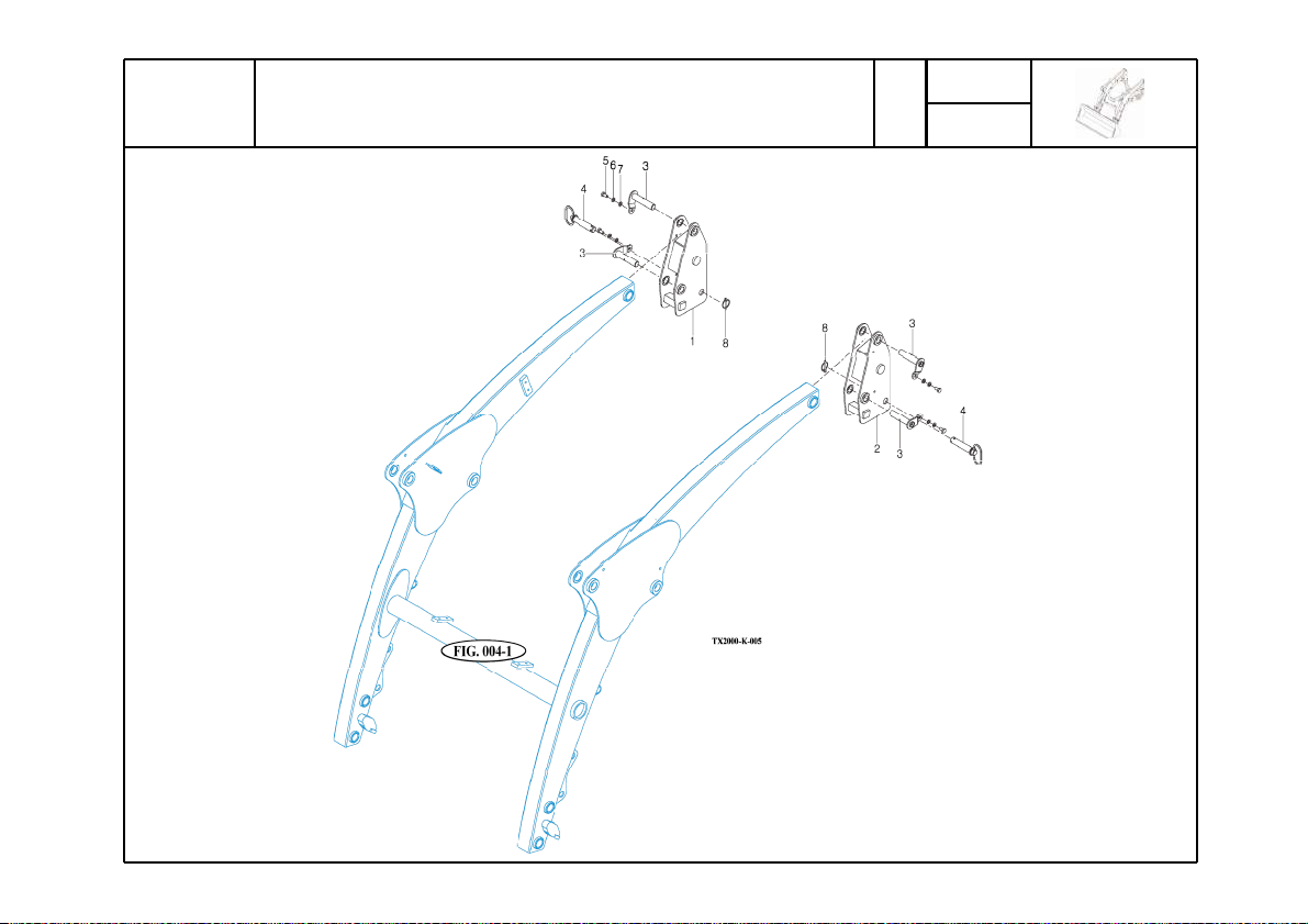
mpnGWW\
wvz{Ghzzltis
TX2000
Year / Month
P1
2011 / 01
- 44 -
Page 45
ΊΖΒΣ;ΠΟΥΙ
mpnGWW\
΄΅Ͳ΄΄Ͷ;ͳͽΊ
KEY NO.
005 001 C1500A3100 COLUMN, RH 1
005 002 C1500A3200 COLUMN, LH 1
005 003 P25A115A PIN
005 004 P25C1030 PIN
005 005 BH1044150Z BOLT(10.9T) M10X20L 4
005 006 WS10M SPRING WASHER M10 4
005 007 WP10M PLAIN WASHER M10 4
005 008 AL20989990 LINK PIN 2
PART NO. DESCRIPSTION SPEC. QTY. EFFECTIVE DATE REMARKS
Ժ
Ժ
4
2
- 45 -
Page 46
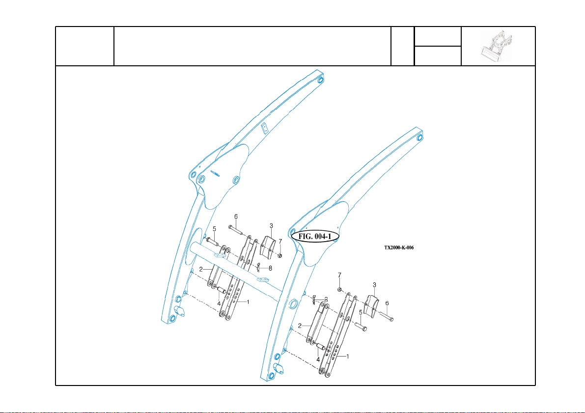
mpnGWW]
z{hukGMGzhml{Gihy
TX2000
Year / Month
P1
2011 / 01
- 46 -
Page 47
ΊΖΒΣ;ΠΟΥΙ
ͽ
ͽ
mpnGWW]
΄΅ͲͿ͵΄ͲͷͶ΅ΊͳͲ
KEY NO.
006 001 1400B8100 STAND 2
006 002 1400B8200 BRACKET 4T 2
006 003 4060A8400 BRACKET 4T 2
006 004 4060A8520 PIN
006 005 4060A8530 PIN
006 006 BH1216175Z BOLT(10.9T) M12X90L 2
006 007 NL12175Z LOCK NUT M12 2
006 008 PR30045 R-PIN
PART NO. DESCRIPSTION SPEC. QTY. EFFECTIVE DATE REMARKS
ԺΉ
ԺΉ
Ժ
2
2
2
- 47 -
Page 48
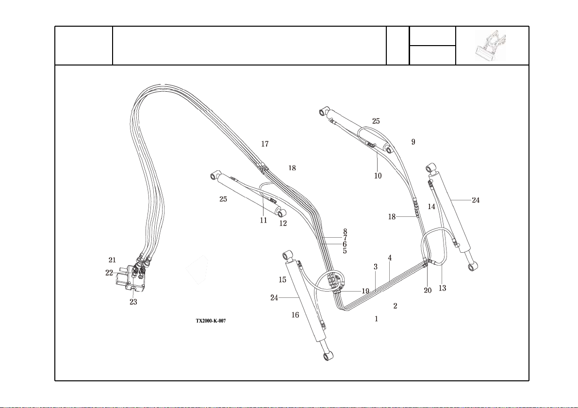
mpnGWW^
okyh|spjGwpwpunGhzzltis
TX2000
Year / Month
P1
2011 / 01
- 48 -
Page 49
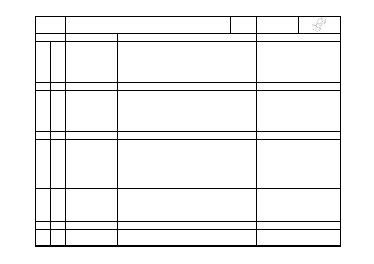
ΊΖΒΣ;ΠΟΥΙ
mpnGWW^
Ί͵ͲΆͽͺʹͺͺͿͲ΄΄Ͷ;ͳͽΊ
007
025
C1600C8000
BOOM CYLINDER
2
KEY NO.
007 001 C1600A071100 PIPE 1
007 002 C1600A071200 PIPE 1
007 003 C1600A071300 PIPE 1
007 004 C1600A071400 PIPE 1
007 005 C1600A071500 PIPE 1
007 006 C1600A071600 PIPE 1
007 007 C1600A071700 PIPE 1
007 008 C1600A071800 PIPE 1
007 009 5PG10330 HOSE ASS'Y 1
007 010 5PG11210 HOSE ASS'Y 1
007 011 5PG10240 HOSE ASS'Y 1
007 012 5PG11220 HOSE ASS'Y 1
007 013 5PG10030 HOSE ASS'Y 1
007 014 5PG10160 HOSE ASS'Y 1
007 015 5PG10580 HOSE ASS'Y 1
007 016 5PG10360 HOSE ASS'Y 1
007 017 3P810900 HOSE ASS'Y 4
007 018 ALK28079800 NIPPLE 6
007 019 ALK28079900 TEE NIPPLE 4
007 020 ALK28079600 ELBOW NIPPLE 2
007 021 ALK28077100 Quick COUPLING(F) 4
007 022 ALK28077200 Quick COUPLING(M) 4
007 023 T293A070010 O-RING NIPPLE 4
007 024 C1600C9000 BUCKET CYLINDER 2
PART NO. DESCRIPSTION SPEC. QTY. EFFECTIVE DATE REMARKS
- 49 -
Page 50
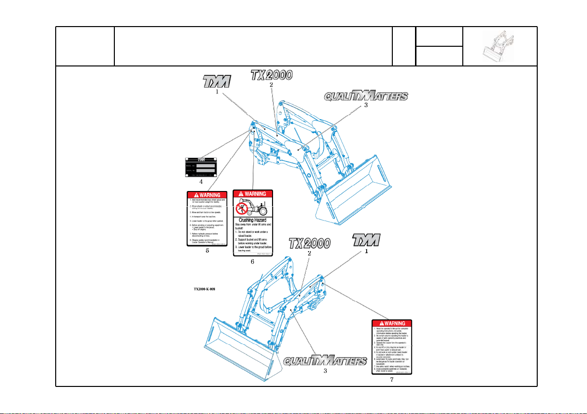
mpnGWW_
kljhs
TX2000
Year / Month
P1
2011 / 01
- 50 -
Page 51
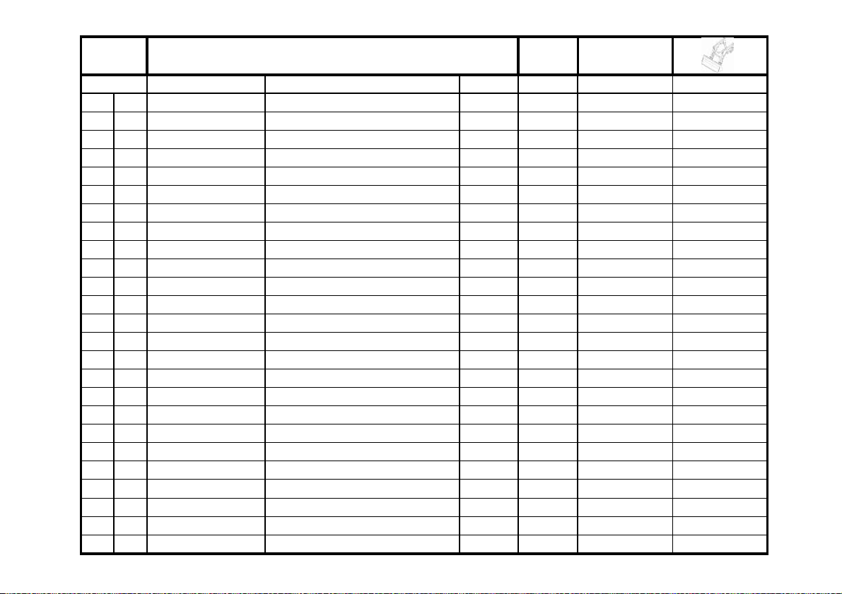
ΊΖΒΣ;ΠΟΥΙ
mpnGWW_
͵ͶʹͲͽ
KEY NO.
008 001 19129041130 LABEL, TYM 0.2T 2
008 002 86005000010 LABEL, ORNAMENT 0.2T 2
008 003 19959100060 LABEL, HOOD 0.05T 2
008 004 85405000070 PLATE, NAME 0.05T 1
008 005 85405000060 LABEL, WARNING(NOTE) 0.05T 1
008 006 85405000040 LABEL, WARNING(CRUSH) 0.05T 1
008 007 85405000050 LABEL, WARNING(OPERATION) 0.05T 1
PART NO. DESCRIPSTION SPEC. QTY. EFFECTIVE DATE REMARKS
- 51 -
Page 52
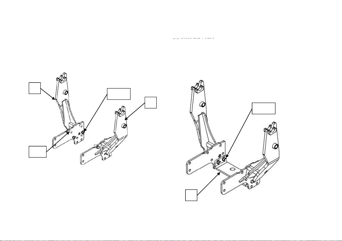
LOADER INSTALLATION
(1) Cross Bar : 1EA
1
Install M
R
CAUTION:
See your Loader Operator’s manual for Safety Precautions and Tractor
Preparations
STEP 1.
Position tractor on hard level surface.
STEP 2.
Release loader, bucket and mount kit box from pallet.
2
3,4,5
3,4
STEP 3.
ounting Frame-L and mounting Frame-
(1) Mounting Frame-LH : 1EA
(2) Mounting Frame-RH : 1EA
(3) Hex Head Bolt M16X2.0PX45L : 8EA
(4) Spring Washer Ø16 : 8EA
(5) Hex Head Nut M16X2.0P : 8EA
STEP 4.
Install Cross bar
(2) Hex Head Bolt M16X2.0PX45L : 4EA
(3) Spring Washer Ø16 : 4EA
(4) Hex Head Nut M16X2.0P : 4EA
2,3,4
1
- 52 -
Page 53
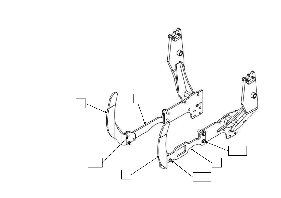
LOADER INSTALLATION
(4) B
1EA
STEP 5.
Install Grill Guard
(1) Grill Guard RH : 1EA
(2) Grill Guard LH : 1EA
(3) Bracket RH : 1EA
racket LH :
(5) Hex Head Bolt M12X1.75PX40L : 4EA
(6) Hex Head Bolt M12X1.75PX50L : 2EA
(7) Spring Washer Ø12 : 6EA
(8) Hex Head Nut M12X1.75P : 2EA
(9) Hex Head Bolt M16X2.0PX55L : 4EA
(10) Spring Washer Ø16 : 4EA
1
3
9,10
5,7 4
2
- 53 -
6,7,8
Page 54
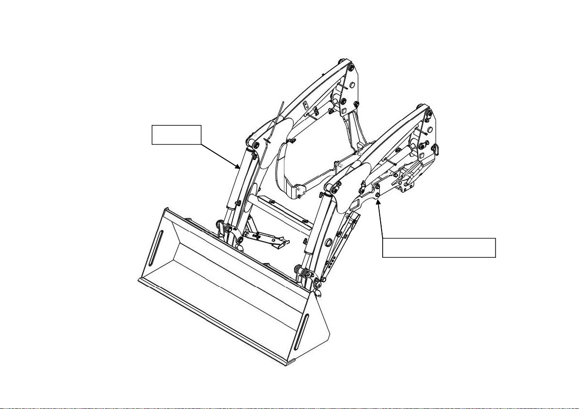
LOADER INSTALLATION
STEP 7.
Install Boom ASS’Y
Hang the groove on the pin located on Mounting Frame
Loader
Mounting Frame Ass’y
- 54 -
Page 55
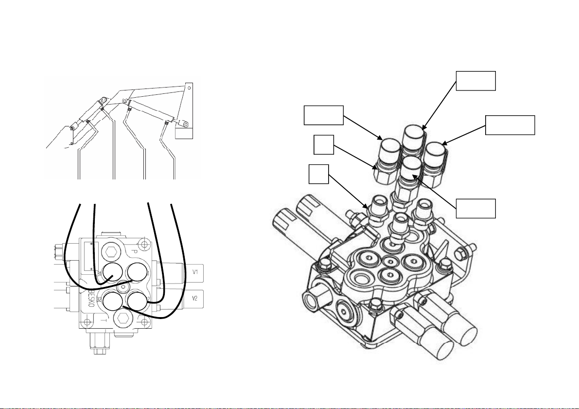
LOADER INSTALLATION
I
k
1
k
yGijkhiG|iiG
AB
C D
STEP 8.
nstall Hydraulic Line
(1) Adapter PF3/8-PT3/8 : 4EA
(2) Quick Coupler PT3/8 : 4EA
Blac
2
Red
Yellow
Blue
- 55 -
Page 56

FRONT END LOADER HISTORY CARD
DATE JOB CARD
NO.
NATURE OF
DEFECT
PARTS REPLACEMENT W/CLAIM NO. AND DATE REMARKS
- 56 -
Page 57

SERVICE RECORD
DATE TRACTOR HOURS NATURE/TYPE OF REPAIR/SERVICE CARRIED OUT
- 57 -
Page 58
DAILY OPERATION LOG
START
END
DATE JOB DONE MACHINE HOURS FUEL CONSUMPTION ENGINE OIL
TOPPED UP
REMARKS
- 58 -
Page 59

PART REPLACEMENT RECORD
DATE PART DESCRIPTION QTY COST DATE PART DESCRIPTION QTY COST
- 59 -
Page 60

TX2000
8670
700-000-0
OPERATOR’S MANUAL FOR FRONT END LOADER
CODE NO.
-
Printed on JANUARY. 2011
1st EDITION
 Loading...