

TYM
OPERATOR’S MANUAL
FOR
TRACTORS
(T454HST/T554HST)
DaeYong B/D, 7, Eonju-ro 133-gil, Gangnam-gu, Seoul, Korea ■TEL: 82-2-3014-2800, FAX:82-2-3014-2852 ■www.tym.co.kr


1
YANMAR LIMITED WARRANTY
What is Covered by this Warranty?
YANMAR warrants to the original retail purchaser that a new YANMAR T NV common r ail series industrial
engine will be free from defects in material and/or workmanship for the duration of the warranty period.
Note: YANMAR engines may be equipped with external components including, but not limited to: wiring
harnesses, electrical devices, control panels, radiator, air filters, fuel/or exhaust systems that are supplied
and/or installed b y manufac tur e r s other tha n YANM AR. For warranty informatio n on such exte r nal
components, please contact the machine or component manufacturer directly or see your authorized
YANMAR dealer or distributor.
This warranty is provided in lieu of all other warranties, express or implied. YANMAR sp ecifically d isclaims
any implied warranties of merchantability or fitness for a particular purpose, except where such disclaimer
is prohibited by law. If such disclaimer is prohibited by law, then implied warranties shall be limited in
duration to the life of the express warranty.
How Long is the Warranty Period?
The YANMAR standard limited warranty period runs for a period of twenty-four (24) months or
two-thousand(2000) engine operation hours, whichever occurs first. An extended limited warranty of
thirty-six(36) mont hs or thre e t hous and ( 30 0 0 ) e ngine o p e ra ting ho ur s, whiche ver occur s fir st, is pro vid e d
for these specific parts only: the cylinder block, cylinder head, crankshaft forging, connecting rods,
flywheel, flywheel housing, camshaft, timing gear, and gear case. The warranty period for both the
Standard limited warranty and the extended limited warranty (by duration or operation hours) begins on the
date of delivery to the original retail purchaser and is valid only until the applicable warranted duration has
passed or the operation hours are exceeded, whichever comes first.
YANMAR
WARRANTIES

2
YANMAR limited warranty- continued
What the Engine Owner must Do:
If you believe your YANMAR engine has experienced a failure due to a defect in material and/or workmanship, your must contact an authorized
YANMAR industrial engine dealer or distributor within thirty (30) Day s of discov e ri ng the failure, You must provide proof of ownership of the engine ,
proof of the date of the engine purchase and delivery, and documentation of the engine operation hours. Acceptable forms of proof of delivery date
include, but ar e not limited to: the original war ra nt y registrat ion of sales receipts or other docume nt s maintained in the ordinary course of business by
YANMAR dealers and/or dis t r ibut ors , indicating the date of del iv ery of the YANMAR product to the orig ina l r e ta i l purc ha s e r , This information is
necessary to establish whether the YANMAR product is still within the wa r r a nty period. Thus, YANMAR strongly recomm e nds you register your
engine as soon as possible after purchase in order to facilitate any future warranty matters.
You are responsible for the transportation of the engine to and from the repair loca t ion a s des ignated by YANMAR.
To Locate an Authorized YANMAR Industrial Engine Dealer or Distributor:
You can locate your nearest authorized YANMAR industrial engine dealer or distributor by visiting the YANMAR Co,. Ltd. Website at:
http://www.yanmar.co.jp (The Japanese language page will be displayed.) For English lan guage “click” on “English Page.”)
● “click” on “Network” in the website heading to vies the “Yanmar Worldwide Network.”
● Choose and “Click” on the desired product group.
● “Click” on the Icon closest to your region.
● “Click” on the desired country or associate company to locate your nearest authorized YANMAR Industrial engine dealer or distributor.
You may also contac t YANMAR by clicking on “Inquiry” in the w e bs i te heading and typing in your question
or comme nt .
What Y ANMAR will DO:
YANMAR warrants to the original retail purchaser of a new YANMAR engine that YANMAR will make such repairs and/or replacements at
YANMAR ’s option, of any part(s) of the YANMAR product covered by this warranty found to be defective in material and/or w or kmanship. Such
repairs and/or replacements will be made at a location designated by YANMAR at no cost to the purchaser for parts or labor.

3
This warranty does not cover parts affected by or damaged by ant reason other than defective materials or workmanship, including, bur not
limited to, accident, misuse, abuse, “Acts of God,” neglect, improper installation, improper maintenance, improper storage, the use of
unsuitable attachments or parts, the use of contaminated fuels, the use of fuels, oils, lubricants, or fluids other than those recommended in your
YANMAR Operation M a nua l, una ut hori z e d a l terations or modifica t ions , ordina r y wear and tear, and rust or corrosion. This warranty does not
cover the cost of parts a nd/or labor required to perform normal/sc he dule d maintenance on your YANM AR engine. This wa rr a nt y does not
cover consum a ble parts such as, but not limited to, f il te r s , bel ts , hoses, fuel injector, lubricants and cleaning fluids. T hi s warranty
does not cover the cos t of shipping the product to or form the warra nty repair fac i li ty.
Warranty Limitations:
The foregoing is YANMAR’s only obligation to you and your exclusive remedy for breach of Warranty. F ailure to follow the
requirements for sub mitting a claim under this warranty may result in a waiver of all claims for damages and other relief.
In no event shall YA NMAR or any authorized Industrial eng i ne deal er or di st ri butor be liable for i nci dent al , spe ci al o r cons equential
damages.
Such consequential damages may include, but not be limited to, loss of revenue, loan payments, cost of rental of substitute equipment,
insurance cov e r a ge, storage, lodging, transpor ta t ion, fuel mileage, and telephone c os ts . The limitations in this wa r r a nty apply regardless of
whether your clai ms are based on breach of contract, tor t( i nc ludi ng negligence and stric t lia bil it y) or any other theory. Any action arising
hereunder must be brought within one (1) yea r aft e r the cause of ac ti on a c c r ue s or it sha ll be bar r e d. S ome states and countries do not allow
certain limitations on warranties or for breach of warranties.
This warranty gives you specific legal rights, and you may also have other rights which vary form st ate to state and country to country.
Limitations set forth in this paragraph shall not apply to the extent that they are prohibited by law.
Warranty Modifications:
Except as modified in writing and signed by the parties, this warranty is and shall remain the complete and exclusive agreement between the
parties with respect to warranties, superseding all prior agreements, written and oral, and all other communications between the parties relating
to warranties. No person or entity is authorized to give any other warranty or to assume any other obligation on behalf of YANMAR,
either orally or in writing.
Questions:
If you have any questions or concerns regarding this warranty, please call or write to the nearest
authorized Y ANMAR industrial engine deal e r or distri butor or other authorized fa c i li ty.
YANMAR limited warranty- continued
What is no Covered by this Warranty?

EMISSION SYSTEM WARRANTY
YANMAR CO., LTD. LIMITED EMISSION CONTROL SYSTEM
WARRANTY – USA ONLY
Your Warranty Rights and Obligations:
■
California
The California Air Resources Board (CARB), the Environmental Protection Agency (EPA) and YANMAR Co,. Ltd. hereafter referred to as
YANMAR, are pleased to explain the emission control system warranty on your industrial compres sion-ig nition engine. In California,
model year 2000 or later off-road compression-igniti on e ng i ne s m us t be designed, built and equipped to meet the state’s stringent anti-smog
standards. In a ll sta tes, 1998 and later non-road compre ss ion-ig nition e ngi nes mus t be designed, built and equippe d to me et the United States EPA
emissions standa rds . Y ANMAR warrants the emissi on contr ol s ystem on your engine for the periods of time listed below provided there has been no
abuse, neglect or improper maintenance of your engine.
Your emission contr ol s ystem may include parts such as the fuel injection system, the air induction s ystem, the electronic control system ,
EGR(Exhaust Gas Recirculation) system and Diesel Particulate Filter. Also included may be hoses, belts, connectors and other emission-related
assemblies.
Where a warrantable condition exists, YANMAR will repair your non-rod compres sion-ignition engine at no charge to you including
diagnosis, par ts a nd l a bor .
Manufacturer’s Warranty Period:
The model year 1998 or later certified and labeled non-roa d com pr es sion-ignition engines are warranted for the periods listed below.
If any emission-related part on your engine is found to be defective during the applicable warranty period, the part will be replaced by YANMAR.
If your engine i s
certified as
And its maximum
Power is
And its rated speed
is
Then its warranty period is
Variable speed or
Constant speed
kW<19 Any speed 1,500 hours or two (2) years whichever comes first. In the absence of a device to
measure t he hours of use, The eng ine has a warranty period of two( 2) years.
Constant speed 19 ≤ kW < 37 3,000rpm or higher 1,500 hours or two (2) years w hic hever comes fir s t. In the absence of a device to
measure t he hours of use, The eng ine has a warranty period of two( 2) years/
Constant speed 19 ≤ kW <37 Less than 3,000rpm 3,00hours of five (5) years whichever comes first. In the absence of a device to
measure t he hours of use, the Engine has a warranty period of five(5) years.
Variable speed 19 ≤ kW <37 Any speed 3,000 hours or five (5) years whichever comes first. In the absence of a device to
measure the hour s of use, the eng ine has a w arr anty per iod o f five (5) y e ar s.
Variable speed or
Constant spee d
kW ≥ 37 Any speed 3,000 hours or (5) years whichever comes fir s t. In the absence of a device to
measure t he hours of use, The eng ine has a warranty period of five (5) years.
4

5
Limited emission control system warranty – USA only – continued
Warranty Coverage:
This warranty is transferable to each subsequent purchaser for the duration of the warranty period. Repair or replacement of any warranted part
will be performed at an authorized YANMAR industrial engine dealer or distributor.
Warranted parts no t scheduled for replacement as required maintenance in the operation manual shall be warranted for the warranty period.
Warranted parts scheduled for replacement as required maintenance i n the operation manual are warranted for the period of time prior to the first
scheduled replacement. Any part repaired or replaced under warranty shall be warranted for the remaining warranty period.
During the warranty period, YANMAR is liable for damages to other engine components caused by the failure of any warranted part during the
warranty period.
Any replacement part which is functionally identical to the original equipment part in all respects may be used in the maintenance or repair of
your engine, and s ha ll not r e duc e YANMAR’s warranty obligati ons . Add-on or modified parts that are not e x e mpted may not be used, The use of
any non-exempted add-on or modified parts shall be grounds for disallowing a warranty.
Warranted Parts:
This warranty covers engine components that are a part of the emission control system of the engine as Delivered by YANMAR to the original
retail purchase r , S uc h c omponents may include the fol lowing:
● Fuel injection system
● Electronic control system
● Cold start enrichment system
● Intake manifold
●Turbocharger systems
● Exhaust ma ni fold
● EGR system
● Positive crankcase ventilation system
● Hoses, belts, connectors and assemblies associated with emission control systems
● Exhaust gas after treatment (Diesel Par ticu lat e Filter (DPF)
Since emissions-related parts may vary sli ghtly between models, certain models may not cont ain all of These parts and other models may contain
the functional e quivalents.

6
Limited emission control system warranty – USA only – continued
Exclusions:
Failures other tha n t hos e a r is i ng f rom defects in material and/or w orkmanship are not covered by this warranty. The warranty does not extend to
the following: malfunctions caused by abuse, misuse, improper Adjustment, modification, alteration, tampering, disconnection, improper or
inadequate m a i nte nance or use Of non-recommended fuels and lubricating oils; accident-caused damage, and replacement of expendable
Items made in connecti on with scheduled maintena nc e . YA N M AR disclaims any respons i bil it y for Incidental or consequent ial damages such as
loss of time, inconvenience, loss of use of equipment/engine Or commercial loss.
Owner’s Warranty Responsibilities:
As the engine owner, you are responsible for the performance of the required maintenance listed in Your owner’s manual.
YANMAR recommends that you retain all documentation, including receipts, covering maintenance on your non-road compression-ignition
engine, but YA N M AR cannot deny War r a nty solely for the lack of receipts, or f or your f a i lur e to ens ur e the pe r formance of all scheduled
maintenance.
YANMAR may deny your warranty coverage of your non-road compres sion-ignition engine if a part has Faile d due to a bus e , neg l e c t, improper
maintenance or unapproved modifications. Your engine is designed to operate on diesel fuel only. Use of any other fuel may result in your engine
no Longer operati ng i n c ompliance with applicable emissions requirements.
You are responsible for initiating the warranty process. You must present your engine to a YANMAR dealer As soon as a problem exists. The
warranty repairs should be completed by the dealer as expeditiously as Possible. If you have any questions regarding your warranty rights and
responsibilitie s , or would like Informa t ion on the ne a r e s t YA NM AR dealer or authoriz e d s e r vice center, you should contact Y ANMAR
America Corporation.
Website: (www.yanmar.com)
E-mail: CS support@yanmar.com
Toll free telephone number: 1-800-872-2867, 1-855-416-7091
7
FOREWARD
Thank you very much for purchasing our tractor, which, we feel sure, will give you many years of troubling the service.
The introduction in this manual set out the correct manner of operating, maintaining and checking the tractor to ensure long-term durability.
Please ensure correct operation of the tracto r as incorrect operatio n can cause substanti al mechanical damage as well as cau se accidents with the
associated inju r ies.
Please note that in some cases differences can exist between this manual and your tractor due to the manufacture’s policy of constant product
improvement.
In the event that you strike a problem not covered by this manual please contact your nearest dealer who will assist you in resolving your
problem.
WARNING
CALIFORNIA Proposition 65 Warning
The Engine Exhaust from this product contains chemicals known to the state of California to cause cancer,birth
defects or other r e pr oduc ti v e harm
WARNING SIGNS IN THIS MANUAL
The following warning signs in this manual draw additional attention to items of importance for the safe and correct operation of the tractor.
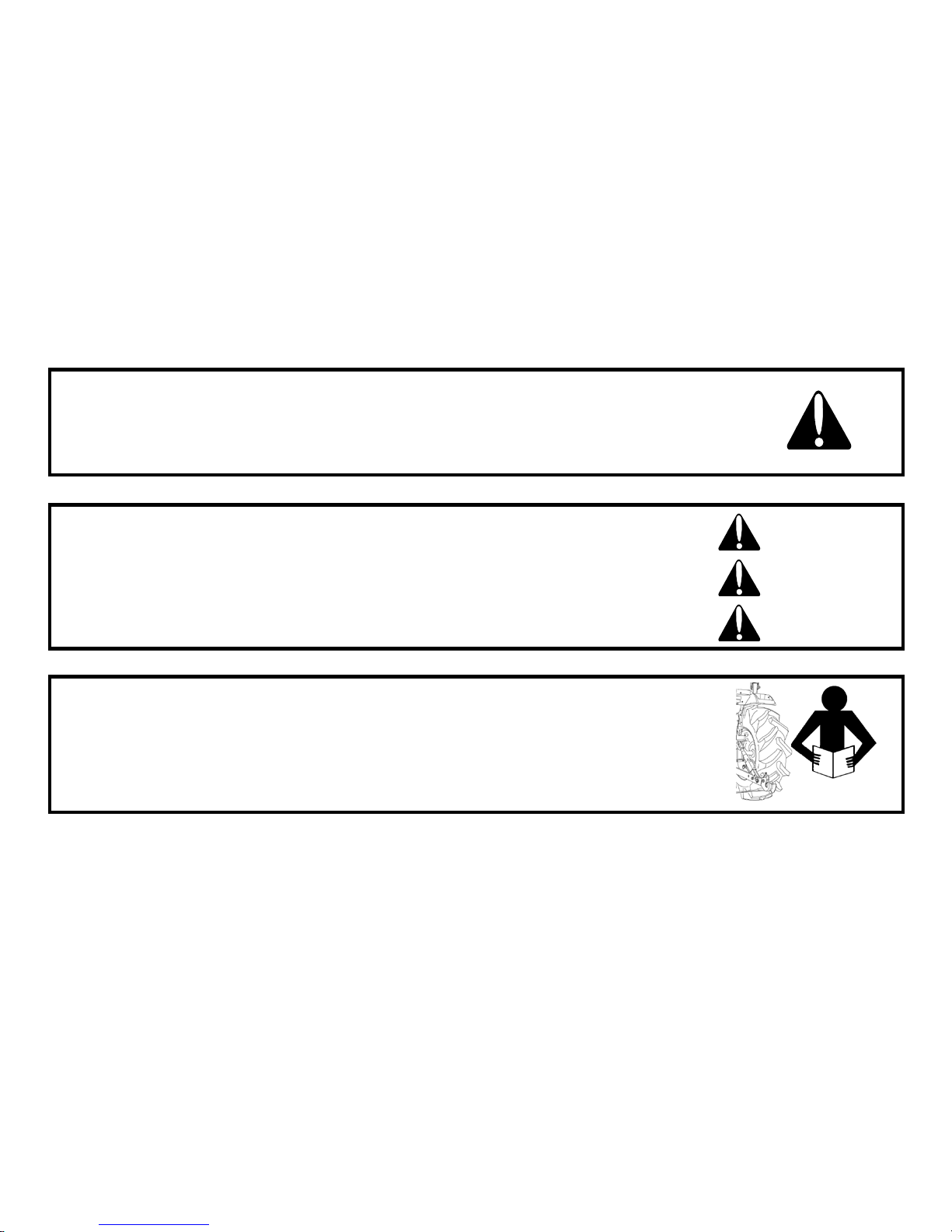
SIGN MEANING OF THE SIGN
Serious hazard with a very high level of risk of either serious injury or death.
Hazard or unsafe practi ce that can lead to severe i njury or death.
Hazard or unsafe practi ce that can lead in inj ury or death.
Instructions for the correct operation of the machine which, if followed, will ensure that it performs at it’s best.
All information,illustrations and specifications in this manual are based on latest information available at the time of publication.The right is
reserved to make changes at any time without notice.
Danger
Warning
Important
Caution

8
CONTENTS
1. Tractor Identification -------------------------------------------------------------------------------------------------------------------
2. About this manual ----------------------------------------------------------------------------------------------------------------------
3. Introduction & Description -------------------------------------------------------------------------------------------------------------
4. Owner assistance ------------------------------------------------------------------------------------------------------------------------
5. ROPS (Roll over protection structures) -----------------------------------------------------------------------------------------------
6. Safety instructions, Do’s & Don’ts ---------------------------------------------------------------------------------------------------
7. Safety signs -------------------------------------------------------------------------------------------------------------------------------
8. Universal symbols -----------------------------------------------------------------------------------------------------------------------
Section A
9. Controls, Instruments & Operations --------------------------------------------------------------------------------------------------
Section B
10. Lubrication & maintenance ----------------------------------------------------------------------------------------------------------
Section C
11. CABIN ------------------------------------------------------------------------------------------------------------------------------
Sr. No. Description Page No.
10
11
12~14
15
16~19
20~35
36~39
40~41
42~77
78~104
105~118

CONTENTS
Section D
12. Specifications -----------------------------------------------------------------------------------------------------------------------
13. Fuel saving Tips ---------------------------------------------------------------------------------------------------------------------
14. Fault tracing ----------------------------------------------------------------------------------------------------------------------
15. Wiring Diagram --------------------------------------------------------------------------------------------------------------------
16. Power train -------------------------------------------------------------------------------------------------------------------------
17. Tractor history card -------------------------------------------------------------------------------------------------------------------
18. Service record -----------------------------------------------------------------------------------------------------------------------
19. Daily operating Log -----------------------------------------------------------------------------------------------------------------
20. Part replacement record -------------------------------------------------------------------------------------------------------------
119~124
125~126
127~130
131~137
138
139
140
141
142
9
All information, illustrations and specifications in this manual are ba sed on latest information a vailable at the time of publication.
The right is reserved to make changes at any time without notice.
Sr. No. Description Page No.
10
TRACTOR IDENTIFICATIO N
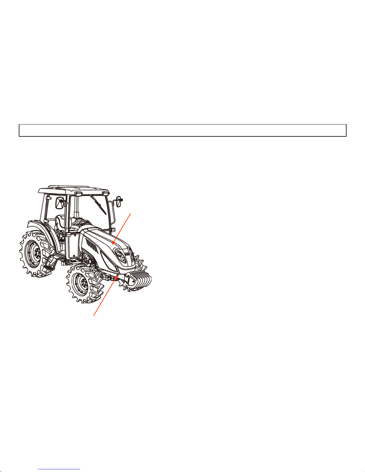
The engine number is stamped on the left hand side of the engine block.
The chassis number is shown on the left hand side of the tractor as shown in the drawing.
Illustration A
WARRANTY OF THE PRODUCT.
The manufacturer warrants this product and full details of
the warranty are provided on a separate
warranty schedule.
SERVICE.
Service is available from any TYM dealer in the country.
PARTS.
To obtain spare parts please contact your nearest dealer
and give him the details listed below.
Tractor model
Tractor serial number
Tractor engine number
Part number and description
Quantity required.
Stamped position of the chassis number
Stamped position
of the Engine type
or Number

11
ABOUT THIS MANUAL
This manual has been prepared to assist you in following/adopting the correct procedure for running-in operation and maintenance
of your new Tong Yang Moolsan CO.,LTD (Here in after refer to TYM) Tractor.
Your Tractor has been designed and built to give maximum performance, with good fuel economy and ease of operation under a
wide variety of operating conditions. Prior to delivery, The tractor was carefully inspected, both at the factory and by your TYM
Dealer/Distributor, to ensure that it reaches you in optimum conditions .To maintain this condition and ensure trouble free
performance. it is important that the routine services, as specified in this manual, are carried out at the recommended intervals.
Read this Manual carefully and keep it in a convenient place for future reference. If at any time you require advice concerning
your Tractor, do not hesitate to contact your Authorized TYM dealer/Distributor. He has trained personnel, genuine parts and
necessary equipments to undertake all your service requirements.
Manufacturer’s policy is one of continuous improvement, and the right to change prices, specifications or equipments at any time
without notice is reserved.
All data given in this book is subject to production variations. Dimensions & weight are approximate only and the illustrations do
not necessarily show Tractors in standard condition. For exact information about any particular Tractor, please consult your TYM
dealer/Distributor.
12
INTRODUCTION & DESCRIPTION
TRACTOR AN INTRODUCTION
The word, ’Tractor’ has been derived from ‘Traction’ which means pulling.
A Tractor is required to pull or haul an equipment, implement or trolley which are coupled to the Tractor body through suitable linkage.
A Tractor can also be used as a prime mover as it has a power outlet source which is also called Power Take or PTO shaft.
In this book the operating, maintenance and storage instructions for all models of TYM Diesel Tractors has been complied.
This material has been prepared in detail to help you in the better understanding of maintenance and efficient operation of the machine.
If you need any information not given in this manual, or require the services of a trained mechanic, please get in touch with the
TYM Dealer/Distributor in your locality. Dealer/Distributors are kept informed of the latest methods of servicing Tractors.
They stock genuine spare parts and are backed by the Company’s full support.
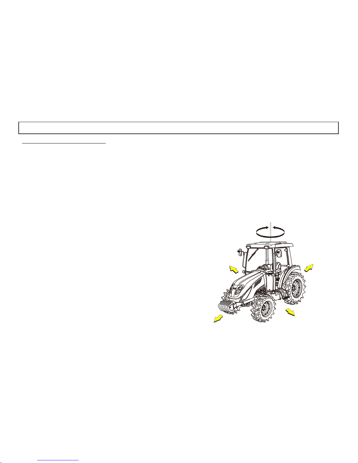
Through thi s manual. The use of the terms LEFT, RIGHT, FRONT
and REAR must be unders tood, to avoid any confusion when
following the intr o d uct io ns. T he LEFT and RIGHT means left and
right sides of the Tractor when facing forward in the driver’s seat,
Reference to the FRONT indicates the radiator end of the Tractor,
while the REAR, indicates the drawbar end ( illustration B)
When spare parts are required, always specify the Tractor and
engine serial number when ordering these parts.(See illustration
A).This will facilitate faster delivery and help ensure that the
correct parts for your particular Tractor is received. The tractor
serial number is punched on a plate attached to the left hand side of
the engine body (illust.A) ,For easy reference, we suggest you to
write the number in the space provided in the owner’s personal
data.
LEFT
RIGHT
FRONT
REAR
RIGHT TURN
(CLOCK WISE)
LEFT TURN
(COUNTER
CLOCK WISE)
illustration B
( Front, Rear,Left,Right Portion)

13
DESCRIPTION
■ General construction
The transmission case, Clutch, Clutch housing, Engine and Front Axle Support are bolted together to form a
rigid unit
■ Front Axle & Wheels
The 4WD front axle is a center-pivot, reverse Eliot t ype. The front wheel drive mechanism is incorporated
as a part of the axle.
The front wheel drive power is taken off the rear transmission and transmitted to the differential in the front
axle where the power is divided into right and left and to the respective final cases.
In the final cases, the transmitted revolution is reduced by the level gears to drive the front wheel. The 4WD
mechanism wit h level gears provides wider s teeri ng and great er durabilit y.
■ Engine
The tractors are fitted with fuel efficient engine with 4 cylinders manufactured by Perkins
■ Hydrostatic Transmission
The Tractor is fitted with servo controlled HST with three ranges and can be selected range by lever. The
tractor has two pedals for speed and forward/reverse control. Tractor with Independent Power Take Off is
fitted with electro – hydraulic clutch Assy .

14
■ Brakes
TYM tractors are provided with independent disc brakes operated by two road travel. A foot brake lever is
fitted for parking.
■ Rear axle & Wheels
This is mounted on ball bearings and is enclosed in removable housi ng which are bolted to the transmission
case. The rim & Disc fitted wi t h Rear ti res are bo lt ed t o the o ut er flan ge o f Rear Axle.
■ Hydraulic system & Linkages.
TYM Tractors are fitted with Live (i.e. system is in operation even when clutch is disengaged.) independent,
very touch of hydraulic System.
Three point Linkages can be used for Category 1 type (USA), or Category 2 type (EU) of implements.
■ Steering
It consists of Hydrostatic Power steering system, which has a hydraulic cylinder and tandem type hydraulic
pump
■ Electrical System
A 12 Volt Lead Acid Propylene Battery is used to activate the Engine through the Starter Motor and the
Electrical system comprising Horn, Head Lamp. Side indicator Lamps, Plough Lamp, Brake Light, Gauge
lamp, Hazard Lamp. Generator or Alternator, Fuse box also from part of the Electrical system.
Warning
When operating the tractor at High speed, Do not attempt to make sharp turns by using the
brakes.This may result in overturning of the Tractor causing serious injury or DEATH.

15
OWNER ASSISTANCE
We at TYM CO.,LTD and your TYM Dealer/Distributor wants you to be completely satisfied with your inv estment.
Normally any problems with your equipment will be handled by your Dealer/Distributor’s Service Departments,
however, misunderstanding can occur. If you feel that your problem has not been handled to your satisfaction, w e
suggest the following.
Contact the owner or General Manager of the Dealership, explain the problem, and request assistance. When additional
assistance is needed, Your Dealer/Distributor has direct access to your office. If you cannot obtain satisfaction by doing
this, contact the TYM CO.,LTD. Office and provide them with;
• Your name, address and telephone number
• Model and Tractor serial number
• Dealer/Distribut or Nam e & Address
• Machine purchase date and Hours used
• Nature of problem
Before contacting TYM CO.,LTD office, be aware that your problem will likely to be resolved in the Dealership using
the Dealer’s/Distributor’s facilities, equipment and personnel. So it is important that your initial contact be with the
Dealer/Distributor.

16
(ROPS) Roll Over Protective Structures
Roll Over Protective Structures (ROPS)
TYM Tractors are equipped with a frame for the protection of operators.
In the case of cab tractors the frame is incorporated in the cab structure.
The objective of the frame or cab structure is to protect the operator in the event of a roll over and they are designed to support
the entire weight of the tractor in that event.
Each TYM ROPS frame or cab structure is designed and has been tested to meet industry and or Government standards.
Included in these tests were all mounting bases and bolts or other fasteners.
DANGER
For ROPS frames to be effective and protect the operato r, t he seat belt prov ided must be worn in order to keep operators
within the ROPS protected area in the event of a roll over.
Failure to use the seat belt can still cause serious injury or death.
On some models the ROPS frame has a fold down feature, which can be used to enter low buildings etc Take care when lowering
the upper section of the ROPS frame and take extreme care while driving the tractor with the ROPS frame lowered.
Do not wear the seat belt with the ROPS lowered and please remember that the fold down facility is for special circumstances
only and must not be lowered for general use.

Use of the tractor with the ROPS lowered can cause fatal injuries.
As the ROPS frame or cab together with the seat belt was designed to meet certain standards, they must be maintained in good
order and condition. To achieve this objective, both the structure and the seat belt should be inspected on a regular basis (every
time the tractor is serviced)
In the event that the seat belt is damaged or frayed, it should be replaced and in the event that the ROPS frame or any part of the
mounting structure is damaged o r cracked, the faulty component must be replaced with a new unit. Such a unit must meet all of
the test criteria of the original unit .Fitment of an inferior item or items affects the certification of the entire ROP S structure and
the effectiveness of the structure in the event of an accident. Drilling or welding of the ROPS struct ure is forbidden.
17
Damage of the ROPS
If the tractor has rolled over or the ROPS has damaged (such
as striking an overhea d ob j ect during transport) , It must be
replaced to provide the original protection. After an accident,
check for damages to the 1.ROPS.2.Seat 3.seat belt & seat
mountings. Before you operate a Tractor, replace all damaged
parts.
(Roll-bar type)
(Cabin type)

18
DO NOT WELD, DRILL OR STRAIGHTEN THE ROPS
Never attach chains, ropes to the ROPS for pulling purposes; this will cause the Tractor to tip backwards.
Always pull from the Tr acto r drawbar . Be careful when d rivi ng thro ugh do or opening o r under lo w overhea d
objects. Make sure there is sufficient overhead clearance for the ROPS fatal injuries
If the ROPS is removed or replaced, make certain that the proper hardware is used to replace the ROPS and the
recommended torque values are applied to the attaching bolts
Always wear your seat belt if the tractor is equipped with ROPS
Warning
Warning
Warning
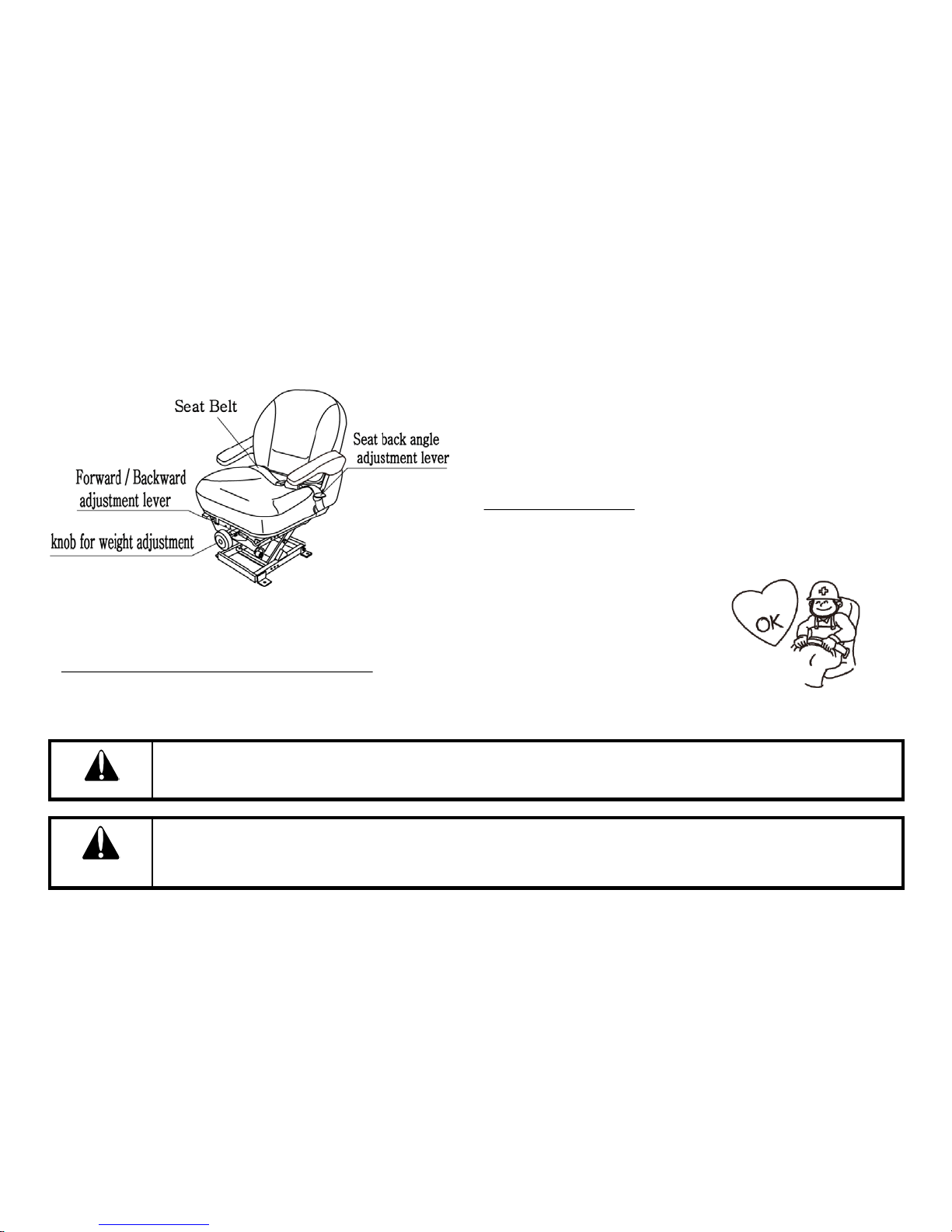
Fig.1
How to adjust the Seat NOTE: Do not use solvents to clean the seat. Use warm water
with a little detergent add e d.
Before operating a Tractor it is important to adjust the seat to
the most comfortable position & check whether it is properly
locked in its position. Figure 1 identifies the seat fitted to your
Tractor.
FOR SLIDING SEAT
To select Seat position, move Adjusting lever and slide Seat
closer to or away from Dash panel and controls.
Check whether the seat proper ly locked in its position before driving the tractor .
Always use the seat belt when the ROPS is installed.Do not use the seat belt if a foldable ROPS is down or there
is no ROPS.Check the seat belt regularly and replace if frayed or damaged.
Danger
Danger
19
SEAT SUSPENSION ADJUSTMENT KNOB
To adjust the seat correctly, turn Weight adjustment knob clockwise or counterclockwise, while seated in the driving position.
20
SAFETY INSTRUCTIONS
SIGNAL WORDS.
A signal word―DANGER, WARNING OR CAUTION―is used with safety aler t symbol.
DANGER identifies the most serious hazards. Safety signs with signal Word ―DANGER OR
WARNING―are typically near specific hazards. General precautions are listed on CAUTION
safety signs.
READ SAFETY INSTRUCTION
Carefully read all safety instructions given in this manual for your safety. Tempering with any of
the safety devices can cause serious injuries or death. Keep all safety signs in good condition.
Replace missing or damaged safety signs.
Keep your tractor in proper condition and do not allow any unauthorized modifications to be
carried out on the Tractor, which may impair the function/safety and affect Tractor life.
RECOGNIZE SAFETY INFORMATION
Thi s symbol means ATTENTION! YOUR SAFETY IS INVOLVED. T he message that follows the
symbol contains important information about safety. Carefully rea d the message
DANGER
WARNING
CAUTION
PROTECTION CHILDR EN
Keep children and others away from the Tractor while operating.
BEFORE YOU REVERSE
- Look behind Tractor for children.
- Do not let children to ride on Tractor or any implement.
USE OF ROPS AND SEAT BELT
The Roll Over Protective Structure(ROPS) has been certified to industry and/or government
standards. Any damage or alternation to the ROPS, mounting hard-ware, or seat belt voids the
certification and will reduce or eliminate pr otec tion for the oper ator in the event of a roll-over . The
ROPS, mounting hardware, and seat belt should be checked after the first 100 hours of Tractor and
every 500 hours thereafter for any evidence of damage, wear or cracks. In the event of damage or
alteration, the ROPS must be replaced prior to further operation of the Tractor.
The seat belt must be worn during machine operation when the machine is equipped with a certified
ROPS.
Failure to do so will reduce or eliminate protection for the operator in the event of a roll over.
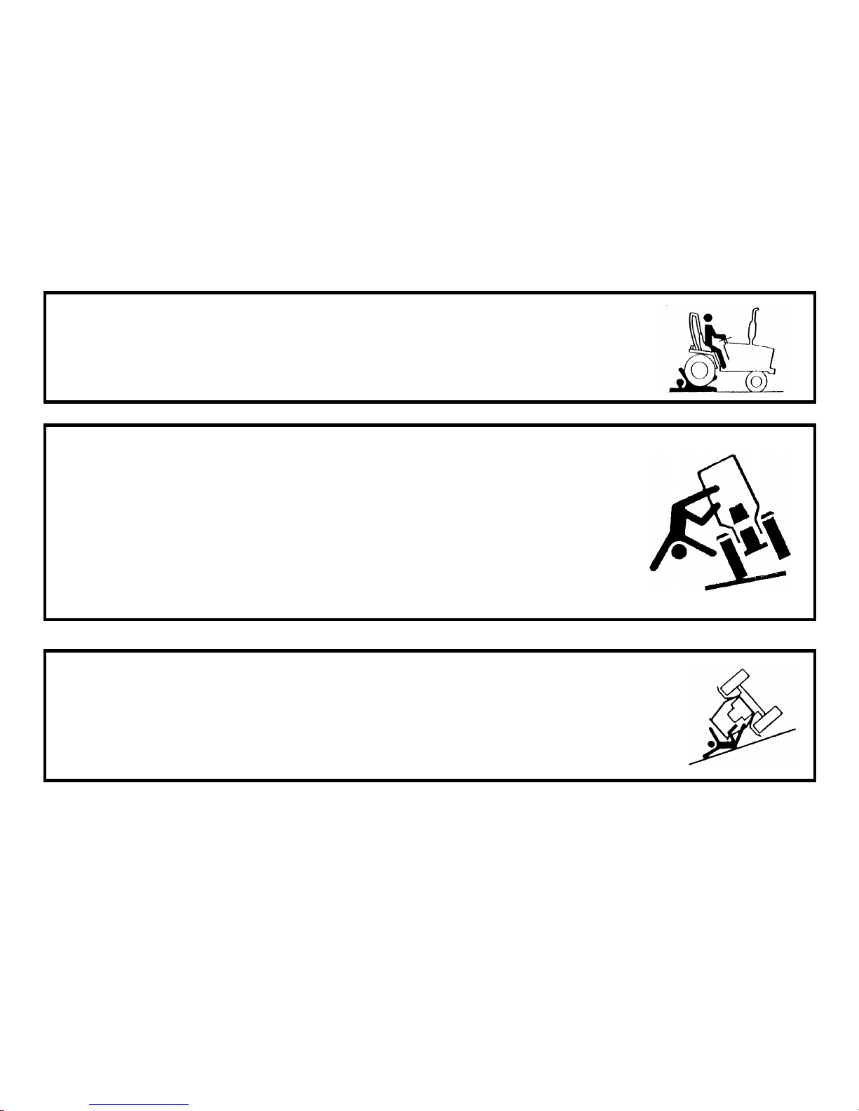
PRECAUTION TO AVOID TIPPING
Do not drive where the Tractor could slip or tip.
Stay alert for holes and rocks in the terrain, and other hidden hazards.
Slow down before you make a sharp turn.
Driving forward out of a ditch or mired condition could cause Tractor to tip over backward. Back out of
these situations if possible
21
22
PARK TRACTOR SAFELY
Before working on the Tractor ;
Lower all equipment to the ground.
Stop the engine and remove t he ke y
KEEP RIDERS OFF TRACTOR
Do not allow riders on the Tractor.
Riders on Tractor are subject to injury such as being stuck by
foreign objects and being thrown off of the Tractor
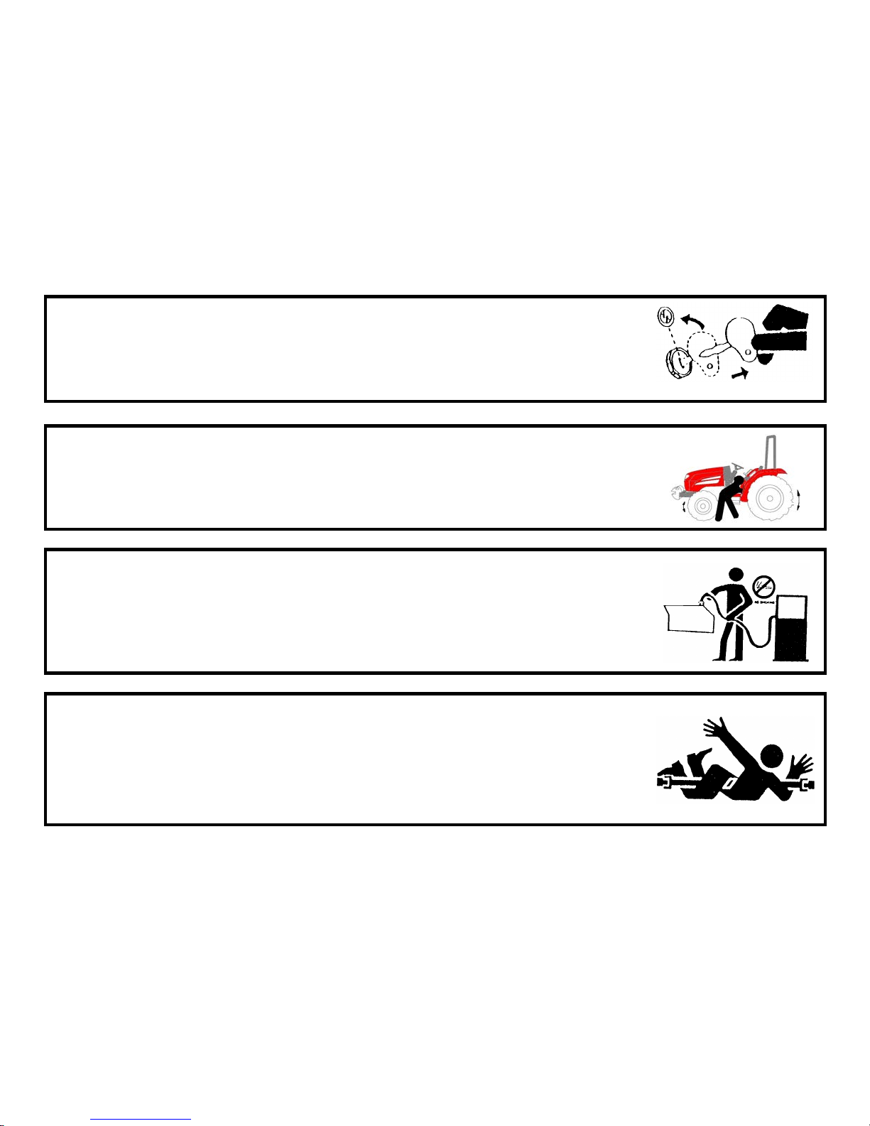
HANDLE FUEL SAFELY-AVOID FIRES
Handle fuel with care; it is highly flammable. Do no t refuel the Tractor while smoking or near
open flame or sparks.
Always stop engine before refueling Tractors.
Always keep your tractor clean of accumulated grease, and debris. Always clean up spilled fuel.
STAY CLEAR OF ROTATING SHAFTS
Entanglement in rotating shaft can cause serious injury or death.
Keep PTO shield in place at all times.
Wear close fitting clothing. Stop the engine and be sure PTO drive is stopped before making
adjustments, co nnectio ns, or cleaning o ut
PTO driven equipment.
23
ALWAYS USE SAFETY LIGHTS AND DEVICES
Use of hazard warning lights a nd tur n signa ls a re re co mmend ed
when towing equipment on public roads unless prohibited by state
or local regulations.
Use slow moving vehicle (SMV) sign when driving on public road
during both day & night time, unless prohibited by law
RACTICE SAFE MAINTENANCE
Understand service procedure before doing work.
Keep the surrounding area of the Tractor clean and dry.
Do not attempt to service Tractor when it is in motion.
Keep body and clothing away from rotating shafts.
Always lower equipment to the ground. Stop the engine.
Remove the key. Allow Tractor to cool before any work repair is caused on it.
Securely support any Tractor elements that must be raised for service work.
Keep all parts in good condition and properly installed.
Replace worn or broken parts. Replace damage/missing decals.
Remove any buildup of grease or oil from the Tractor.
Disconnect battery ground cable(−) before making adjustments on electrical systems or
welding on Tractor
24
AVOID HIGH-PRESSURE FLUIDS
Escaping fluid under pressure can penetrate the skin causing serious injury. Keep hands and body away
from pinholes a nd no zz les , which eject fluids und e r hi gh p r ess ure . I f ANY flui d is inj ec te d into the ski n.
Consult your doctor immediately.
PREVENT BATTERY EX PLO SION S
Keep sparks, lighted matches, and open flame away from the top of battery. Battery gas can explode.
Never check battery charge by placing a metal object across the poles.
PREVENT ACID BURNS
Sulfuric acid in battery electrolyte is poisonous. It is strong enough to burn skin, cause holes
in clothing and cause blindness if found entry into eyes.
For adequate safety always;
1.Fill batteries in a well-ventilated area.
2.Wear eye protection and acid proof hand gloves
3. Avoid breathing direct fumes when electrolyte is added.
4. Do not add water to electrolyte as it may splash off causing severe burns.
If you spill acid on yourself;
1.Flush your skin with water.
2.Flush your eyes with wate r for 10-15 minutes. Get medical attention immediately.
25
SERVICE TRACTOR SAFELY
Do not wear a necktie, scarf or loose clothing when you work near
moving parts. If these items were to get caught, severe injury could result.
Remove rings and other jeweler to prevent electrical shorts and
entanglement in moving parts.
TRACTOR RUNAWAY
1. The tractor can start even if the transmission is engaged position causing Tractor to runaway and serious injury to the people
standing nearby the tractor.
2. For additional safety keep the pull to stop knob (fuel shut off control) in fully pulled o ut position.
Transmission in neutral position, Foot brake engaged and PTO lever in disengaged position while attending to Safety Starter
Switch or any other work on Tractor.
WORK IN VENTILATED AREA
Do not start the Tractor in an enclosed building unless the doors &
windows are open for proper ventilation, as tractor fumes can cause
sickness or death. If it is necessary to run an engine in an enclosed area
remove the exhaust fumes by connecti ng exhaust p ipe extension.

26
Safety Starter Switch is to be replaced after every 2000 hours/4 years, whichever is earlier
SAFETY STARTER SWITCH
1. Clutch operated safety switch is provided on all Tractors which allow the starting system to
become operational only when the Clutch pedal is fully pressed.
2. Do not By-pass this safety starter switch or work on it. Only Authorized Dealers are
recommended to work on safety starter switch.
3. On some models Safety Star te r switch is provided on transmission High-low shifter lever and in
PTO shifter lever.The tractor can be started only if High-low shifter lever is in neutral position.
Caution

27
SAFE OPERATION OF YOUR TRACTOR
The manufacturer of your tractor has made every effort to make it as safe as is humanly possible.
Beyond this point it is the responsibility of the operator to avoid accidents and we ask that you read and implement our
suggestions fo r your sa fety.
Ensure that only trained and competent operators use this tract or and ensure that they are fully conversant with the
machine and aware of all it’s control and safe ty featur es .
Operators should not operate the tractor or associated machinery while tired or untrained.
To avoid accidents please ensure that the op erato r wears clo thing which will not get entangled in the moving parts of the tractor
or machine and protect him or her from the elements.
When spraying or using chemicals, please ensure that clothing and protective equipment is worn which prevents respiratory or
skin problems.
For full details consult the manufacturer of the chemicals.
To avoid lengthy e xp os ure to noise ens ure that ea r pr o te ct io n is worn.
If adjustment to the tractor or machinery need to be made ensure the tractor or machine are turned off beforehand.
Use of certified Roll Over Protection Structure ( ROPS) is a must while operating a tr a c tor.
Use of seat belt is a must while operating a tractor.
In summary, ensure at all times that the safety of the operator and any other worker is paramount.

28
SAFETY TIPS DURING MAINTENANCE
1. At least on a daily basis check all oil levels. Water level in the radiator and electrolyte level in the battery and perform services
according to the service schedule.
2. Ensure tire pressure are even and the correct pressure for the job being done is maintained.
3. Check to ensure that the all controls and preventative mechanisms of the Tractor and implement work correctly and effecti vel y.
4. Ensure that an adequate set of the correct tools is available for maintenance and minor repairs.
5. Ensure that all service work and repairs are carried out on a flat area with a concrete or similar floor.
Do not carry out service work on a tractor until it is switched off, and the parking brake applied and wheels choked.
Where a tractor is started in a confined area, ensure that the area is well ventilated as exhaust gases are very harmful, and can
cause death.
6. Do not work under raised implements.
7. When changing wheels or tires ensure that a suitable wheel stand is placed under the axle prior to removing the wheel and the
wheels are chocked.
8. Where guards or shields need to be removed to perform a service or rep air, ensure that the guard or shield is correctly
reinstalled before starting the Tracto r.
9. Never refuel near an open flame or with an overheated engine. Ensure to turn off Engine before refueling.
10. The cooling system operates under pressure, take care when removing the Radiator cap on a hot engine to prevent being
scalded by steam or hot water. Do not add water in the radiator when the engine is hot. Add water to the radiator only after
the engine cools down completely.
11.To prevent fires keep the tractor including the engine clean and free from inflammable material and well away from fuels and
other inflammable material.

29
► MOUNTING AND DEMOUNTING IMPLEMENTS
(1)Ensure that all mount ing and removal of implements is done on safe flat ground. Ensure no one is between the Tractor and
implement and do not get under the implement to avoid accidental injuries.
(2) After mounting the implement, ensure that all sway chains are correctly adjusted and, where PTO shafts are used that the shaft
is fitted and secured correctly.
(3) Where heavy implements are used, ensure that the combination is well balanced or use proper ballast to achieve balance.
(4) Before leaving the tractor at any time, lower the implement, stop the PTO shaft where ap plicable, set the parking brake and
switch off the engine .
(5) While operating the implements with the PTO keep all bystanders away from any moving par ts and do not attempt to make
adjustments while the machine is running.
(6) Only the driver should ride on the Tractor with the ROPS frame fitted and with the seat belt properly fastened.
(7) Where young children are present, particular care should be taken and the tractor should not be moved until the whereabouts
of all children is known.
(8) Only trained operators should operate the Tractor and so taking care to ensure that o ther workers are not injured. In particular
they should take care during dusty operations, which will reduce visibility substantially.
(9) Never start the tractor unless the transmission is out of gear, the operator is in the seat and all round safety has been checked.
(10) Only operate the tractor seated in the drivers seat and never turn or brake suddenly at high speed as this can cause a roll-over
and serious injury or death.
(11) When traveling on a public road ensure that the tractor and driver both meet all laws relating to safety and licensing.
When traveling with wide implements use red flags on the extremities and observe all legal including escor t req uirements.
(12) When operating under adverse conditions, hilly terrain or on bad ground adjust the speed of the tractor to suit the conditions,
safety comes first. Never drive down hill at high speed or with the transmission in neutral. Use of the braking capacity of the
engine as well as the service brakes.
Do not try to change gear going up or down a steep slope, select the correct gear before starting.
(13) Take care when traveling uphill with a heavy implement to ensure that it does not overbalance and tip up the front end.
(14) Never remove or modify the seat belt.
(15) Never remove, modify or repair the ROPS frame.
PLEASE REMEMBER THAT A LITTLE BIT OF EXTRA CARE C AN PREVENT S ER IOUS INJURY OR TEATH
AND AVOID DAMAGE TO YOUR TRACTOR.

30
The following precautions are suggested to help prevent accidents.
A careful operator is the best operator. Most accidents can be avoided by observing certain precautions .Read and take the
following precautions before operating the Tractor to prevent accidents. Tractor should be operated only by those who are
responsible and properly trained to do so.
■ The Tractor
1. Read the operator’s manual carefully before using the tractor. Lack of operating knowledge can lead to accidents.
2. Use an approved rollover bar and seat belt for safe operation. Overturning of a tractor without a rollover bar can result in death
or injury.
3. Do not remove ROPS (Roll Over Protective Structure). Always use the seat belt.
4. Fiberglass canopy does not give any protection.
5. To prevent falls, keep steps and platform clear of mud and oil.
6. Do not permit anyone but the operator to ride on the Tractor. There is no safety place for extra riders.
7. Replace all missing, illegible or damaged safety signs.
8. Keep safety signs clean of dirt and greas e
■ Servicing the Tractor
1.keep the tractor in good operating condition for your safety. An improperly maintained Tractor can be hazardous.
2. Stop the engine before performing any service on the tractor.
3. The cooling system operates under pressure, which is controlled by the radiator cap. It is dangerous to remove the cap while
the system is hot. First turn the cap slowly to stop and allow the pressure to escape before removing the cap entirely.
4. Do not smoke while the refueling the tractor. Keep away any type of open flame.
5. The fuel in the inj e ct io n system is unde r hi gh pr e ssur e and ca n p e net ra te t he ski n. U nq ual ifie d persons shoul d not remove or
attempt to adjust a pump, injector, nozzle or any part of the fuel injection system.
Failure to follow these instructions can result in serious injury.
6. Keep open flame away from battery or cold weather starting aids to prevent fire or explosions.
7. Do not modify or alter or permit anyone else to modify or alter this tractor or any of its components or any tractor
functions

31
■ Operating the tractor
1. Before starting the tractor apply the parking brake, place the PTO (Power Take Off) lever in the “OFF” position, the
hydraulic control levers in the downward positio n, the remote control valve le ver s in the neutral positio n( if fitted ) and the
transmission in neutral.
2. Do not start the engine or controls while standing besides the tractor. Always sit on the tractor seat when the engine o r
operating controls.
3. Safety starter switch.
In order to prevent the accidental starting of the tractor, a safety switch has been provided. The starting system of the
tractor is connected through this switch, which becomes operative only when the clutch pedal is depressed. On some models
shuttle shifter lever and PTO button should also be in neutral position for completing the starting circuit. Do not by pass the
safety starter switch. Consult your TYM Tractor Dealer/Distributor if safety- starting switch malfunctions.
4. Avoid accidental contact with the gear shifter lever while the engine is running. Unexpected Tractor movement can result from
such contact.
5. Do not get off or climb the tractor while it is in motion.
6. Shut off the engine, r emove t he ke y a nd ap p ly the p a rki ng b r ake b efo r e ge tti ng o ff the tr ac to r .
7. Do not operate the tractor in an enclosed building without adequate ventilation. Exhaust fumes can cause death.
8. Do not park the tractor on a steep slope.
9. If power steering or Engine seizes to operate, stop the tractor immediately.
10. Pull only from the swinging draw ba r or the lower link drawbar in the down position. Use only a drawbar pin that locks in
place. Pulling from the tractor rear axle carriers or any point above the rear axle may cause the Tractor’s front end to lift.
11. If the front end of the tractor tends to rise when heavy implements ar e attached to the three-point linkage, install front end or
front wheel weights. Do not o perate the tractor with a light front end.

12.Always use hydraulic posi tion control lever when attaching equipments/ implement and when transporting equip ment. Be sure
that the hydraulic co uplers are pro perly mounted and will disconnect safely in case of accidental detachment of implement.
13.Do not leave equipment/implement in the raised position.
14.Use the flas her / Turn signal light s and Sl ow M ovi ng Ve hic le ( SM V) signs when d r iving o n pub li c ro ad s dur ing b o th day and
night time, unless prohibited by law.
15.Dim tractor lights when meeting a vehicle at night. Be sure the lights are adjusted to prevent the blinding on the eyes of
coming vehicle operator.
16.Emergency stopping instruction; If trac tor fails to stop even after a pp lication of brakes, P ull the knob of fuel shut off control rod.
■ Driving the tractor
1. Watch where you are going especially at row ends, on roads, around trees and low hanging obstacles.
2. To avoid upsets, drive the tractor with care and at speeds compatible with safety, especially when operating over rough ground,
crossing ditche s or slope s, and when tur ning at cor ner s.
3. Lock the tractor brake pedals together when transporting on roads to provide proper wheel braking.
4. Keep the trac to r i n the sa me gea r when going downhill as used when go i ng up hi ll. Do not coa st o r free wheel d o wn hi lls.
5. Any towed vehicle and/or trailer whose total weight exceed s that o f the towing Tra ctor , must be equipped with its own brakes for
safe operation.
6. When the tractor is stuck or tires are frozen to the ground, back out to prevent upset.
7. Always check overhead clearance, especially when transporting the tractor.
■ Operating the PTO (Power Take Off)
1. When opera ti ng PTO driven equip ment, s hut o ff t he e ngine a nd wait unt il t he P TO stops before get ting o ff t he t ra ct o r and
disconnecting the equip ment.
2. Do not wear loose cl othing when operating the power take-off or near rotati ng equipment.
3. When operating stationery PTO driven equipment, always apply the tractor parking brake and block the rear wheels from front and
rear side.
4. To avoid injury, always move down flip part of PT O. Do not clean, adjust or service PTO driven equipment when the tractor
engine is running.
5. Make sure the PTO master shield is installed at all times and always replace the PT O shield cap When the PTO is not in use.
32

33
■ Diesel fuel
1. Keep the equipment clean and properly maintained.
2. Under no circumstances should gasoline, alcohol or blended fuels be added to diesel fire or explosive hazard. Such blends are
more explosive than pure gasoline. In a closed container, such as a fuel tank. DO NOT USE THESE BLENDS.
3. Never remove the fuel ca p o r refuel the tract or with t he e ngine r unning.
4. Do not smoke while refueling or when s tanding nea r fuel.
5. Maintain control of the fuel filler pipe when filling the tank.
6. Do not fill the fuel tank to capacity. Allow room for expansion.
7.Wipe up spilled fuel immediately.
8.Always tighten the fuel cap securely.
9.If the original fuel tank cap is lost, replace it with genuine cap. A none approved cap may not be safe.
10.Do not drive equipment near open fire.
11.Never use fuel for cleaning purpose.
12.Arrange fuel pur cha ses so that winter gr ad e fuel a re no t held o ver and use d in the sp r ing.
N.B: It is suggested that after repairs if any of the Safety Decal/sign is peeled/defaced, the same may be replaced
immediately in interest of your safety.

DO’S AND DON’T’S
DO’S-For Better performance
DO-Ensure that safety shields are in place and in good c ondit ion.
DO-Read all operating i ns tr uc t ions be fore commencing to operate Tractor.
DO-Carry out all maintenance tasks without fail.
DO-Keep the air cleaner clean.
DO -Ensure that the corr e c t grade of lubricating oils is used and tha t the y are replenished and changed a t the re c ommended intervals.
DO-Fit new sealing rings when the filter elements are changed.
DO-Watch the oil pressure gauge or warning light and investigate any abnormality immediately.
DO-Keep the radiator filled with clean water and in cold weather use anti-freeze mixture. Drain the system only in an emergency and fill before
starting the engine.
DO-Ensure that the transmission is in neutral bef or e star ti ng t he eng ine.
DO-Keep all fuel in clean st orage and use a filter when filling the tank.
DO-Attend to minor adjustments and repairs as soon as necessity is apparent.
DO-Allow the engine to cool be fore removing the radiator f i ll e r cap and addi ng water, remove the radiator cap sl owly.
DO-Shift into low gear when driving down steeps hills.
DO-Latch the brake pedals together when driving on a highway.
DO-Keep draft control lever fully down when not in use.
34

Don’ts-For safe operation
DON’T-Run the engine with the air cleaner disconnected.
DON’T-Start the tractor in a n enclosed building unless the doors and windows are open for proper ventilation.
DON’T-Operate the tractor or engine while lubrica ting or cleaning.
DON’T-Allow the tractor to run out of diesel fuel otherwise it will be necessary to vent the system.
DON’T-Temper the fuel injection pump, If seal is broken the warranty becomes void.
DON’T-Allow the engine to run idle for a long period.
DON’T-Run the engine if it is not firing on all cylinders.
DON’T-Ride the brake or clutch pedal. This will result in excessive wear of the brake lining, clutch driven member and clutch
release bearing.
DON’T-Use the indepe ndent bra kes for making turns o n the highway o r at high speed s.
DON’T-Refuel t he t ra ct or with t he e ngine r unning.
DON’T-Mount or dismount from the right side of the tractor.
DON’T-Temper the hydraulic control levers’ upper limit stops.
DON’T-Use draft control lever for lifting of implements.
DON’T-Start the engine with the PT O engaged.
DON’T-Use the governo r Cont rol Lever (Ha nd thr ottl e) while dr iving on roa ds.
DON’T-Move the hydraulic levers rearward.
35

36
SAFETY SIGNS
(Replace all missing, damaged or illegible signs)
GENERAL SAFETY INFORMATION
IMPORTANT: This “General safety Information” should be kept with the machine at all times as reference data.
This symbol means ATTENTION! YOUR SAFETY IS INVOLVED.
The message that follows the symbol contains important information ab out safety. Fo llow recommended
precautions and safe operating practice.
DECALS ON THE DASH COVER

37
Part No.:1200-910-003-0
Part No.:1200-910-023-0
Part No.:1769-910-009-0
Part No.:1200-910-006-0
Part No.:1200-910-011-0
Part No.:1200-910-004-0
Part No.:1200-910-019-0
DECALS ON THE CHASSIS

38
DECALS ON THE CABIN
Part No.:1200-910-024-0
Part No.:1200-910-005-0
Part No.:1200-910-001-0
Part No.:1200-910-016-0
Part No.:1220-904-122-1
Part No.:1200-910-015-0
Part No.:1200-910-012-0

Part No.:1200-910-011-0
Part No.:1200-910-013-0
Part No.:1769-910-009-0
39

40
UNIVERSAL SYMBOLS
Some of the universa l symbols have b e en sho wn b e lo w with an ind i ca tio n o f their meaning
Engine speed
rev/minX100)
Pressured-
open slowly
Corrosive
substance
Hours,
recorded
Continuous
variable
”Tortoise”
Slow or
minimum Setting
Engine
coolant
temperature
Warning
”Hare” fast or
maximum
setting
Fuel level
Hazard
warning
Transmission
oil pressure
Engine
Stop
control
Neutral Turn signal
Lights
Fan
Transmission
oil temperature

Horn
Power take
off engaged
Parking brake
Engine oil
pressure
Power
take off
disengaged
Work lamps
Air filter
Lift arm/raise
Differential
lock
Battery charge Lift arm/lower
See
operator’s
manual
41
Regen Request Lamp Exhaust Temp Lamp RegenDisable Lamp

42
Section - A
Controls,
Instruments
And
Operations
The following pages in this section detail the location and function of various instruments, switches and controls on your Tractor.
Even if you operate other Tractors, you should read through this section of the manual and ensure that you are thoroughly
familiar with the location and function of all the features of your New Tractor.
Do not start the engine or attempt to drive or operate the Tractor until you are fully accustomed to all the controls. It is too late to
learn once the Tractor is moving. If in doubt about any aspect of the operation of the tractor consult your TYM Tractor
Dealer/Distributor.
Particular attention should be paid to the recommendations for running-in to ensure that your tractor will give long life and
dependable service for which it was intended.

43
DESCRIPTION OF TRACTOR CONTROLS
INSTRUMENT AND SWITCHES

► MAIN SWITCH (KEY SWITCH)
[OFF] - The key can be inserted or removed
[ON] - The electric circuit is on & preheat function
[START] - The starter motor is engaged.
When the key is released it will return to the ON position
[GLOW] - Glow plugs preheat the combustion chamber
► HOUR METER
The hour meter consists of five digits where the last digit
indicates 1/10th of an hour
44
► HEAD LAMP, TURN SIGNAL SWITCH AND HORN
■ HEAD LAMP SWITCH
High and low beam are operated On the main switch
Position ①. Low beam
Position ②. High beam
■ TURN SIGNAL SWITCH
Pull the turn signal lever down to signal a left turn.
Push the turn signal lever up to signal a right turn.
■ HORN
Push the Red button.

45
► TACHOMETER
This meter shows the revolutions of the engine and the
PTO shafts as well as the travel speed in top gear.
►FUEL GAUGE
Shows the amount of fuel in the tank when the ignition switch is ON
►WATER TEMPERATURE GAUGE
This comes on when the coolant temperature is over 110 degrees.
► HAZARD LAMP SWITCH
Push the hazard warning signal once to operate the hazard
warning light. (Left and right turn indicators flash).
Push the hazard warning light switch again to switch off the
hazard warning lights.
Hazard Lamp S/W

► PANEL INSTRUMENT LAMP
High beam lamp is operated on
the combination switch.
Low beam lamp is operated on
the combination switch
Engine oil pressure lamp will go out as soon as the engine starts if the oil pressure is correct.
If it comes on while the engine is running, stop the engine and get expert advice.
Parking brake lamp is operated on when the i gni tion key i s turned onto “ON” with the hand brake e ngaged.
46
PTO monitor Lamp Will turn on when PT O clutch is engaged
Fuel Level indicator lamp. If it comes on while the engine is running, Fill the tank with fuel.

47
Glow signal Lamp is operated on when t he ignition ke y is turned onto “GLOW” o r
“ON” for preheating
Charge lamp
This light will go off as soon as the engine starts to run to indicate that the alternator is changing.
(Please note, as broken fan belt can cause the light to come on, please stop the engine as overheating can
occur if not rectified immediately)
Cruise Control Lamp
Will turn on when cruise control is engaged
Forward indicator lamp is operated when F/R Lever indicated forward ,Rev erse indicator lamp is
operated when F/R Lever indicated reverse
Check Lamp
Will turn on when the key switch is set to ON position and safety start conditions are not satisfied.
Safety start conditions : ① Brake pedal is depressed ② PTO ON/OFF switch is OFF
If it comes on when safety start conditions are satisfied, some electric part is in trouble.
Load Sensing Lamp
Will turn on when load sensing function is activated.

Air cleaner filter contamination indicator
This comes on when the air cleaner is clogged by foreign materi als.
When this comes on, open the cover and clean the inside of the cleaner. Also, blow air
through the filter in the direction of intake air to clean it or replace the filter with a new one.
Cruise control indicator
This comes on while the cr ui s e contr ol ( c ons t a nt s pe e d se t ti ng ) is ac ti v a t e d.)
Exhaust Temp Lamp
This lamp is illuminated when the DPF temperature is over 400 degrees.
Regen Request Lamp
48
See 46page.

■ Regeneration operati on and cautions
RegenReqLamp ACK Lamp
▶ Automatic regeneration
The regeneration pr ocess is automatically being performed when the exhaust temperature
lamp comes on during work.
▶ Disable switch
Press this switch to stop automatic regeneration.
RegenReqLamp ExhaustTempLamp Engine Warni ng L a mp
RegenAck Lamp
& RegenReqSW
RegenDisable Lamp
& RegenDisableSW
▶ Lamp functions
Run the system in a well-ventilated area to secure your safety. If runn in g the system
in a poorly-ventilated area, such as greenhouses, it can lead to gas poisoning.
Caution
▶ It is necessary to activate the regeneration function manually if the engine warning lamp and
regeneration request lamp are illuminated during work.
1. Stop worki ng and park the vehicle on level ground or in a sa fe place.
Engine Warni ng L a mp
+
+
49

ExhaustTempLamp
ACK Lamp
Never move the vehicle to another place during regeneration process. Sudden movement can result in an accident.
Caution
2. Before starti ng re g e ne r a t ion, a pply the parking brake and idle the e ng ine. Then, the ACK lamp blinks.
However , the reg e ne r a ti on process is not performed if the reg e neration activation conditions a r e not sa t is fied.
3. Press and hold the A CK button for 3 seconds and release it. The n, the ACK lamp and exhaust tempera t ur e
lamp are illuminated and the engine speed is increased up to 2200 RPM to perform the regeneration process
for approx. 30 m inut e s .
4. As soon as the regeneration process is completed, all the lamps are turned off.
50

PTO monitor Lamp
■ THE PTO MONITOR LAMP on the dash panel indicates the state of the PTO shaft.
1. If the monitor glows: The PTO is rotating
2. If the monitor is off: The PTO is off
3. If the monitor blinks: The PTO is presently stationary but will instantly start rotating of
the clutch pedal is released or the implements lowered.
Two switches operate the independent PTO.
1.PTO ON/OFF SWITCH: PTO ON/OFF switch is located on the LHS. on the
steering column and ca n be identified easily with its built in red colored
indicator.
When the switch is pushed down to start the PTO indicator glows to indicate that
the switch and t he P TO are in ON positio n, If the switch is pushed do wn aga in
the indicator goes off signaling that the PTO is OFF.
2. PTO CONTROL SWITCH: This switch is located near the starting key
location on the dash panel. There are three p ositions marked for this switch.
■ OFF at the center
■ MANUAL at the left
■ AUTO AT THE RIGHT.
The PTO shaft will not rotate if either of the two switches is in OFF position.
The following table explains how the PTO operates at the two different
(Manual & Auto) positions of the PTO control switch with the PTO ON/OFF switch
in the on position.
PTO control swi t ch
51

PTO
ON/OFF
Switch
PTO
Control
Switch
Clutch Pedal
Hydraulic Position
Control Lever.
PTO Monitor
Lamp on the dash
panel
PTO SHAFT
On
Manual
Mode
Either pressed or
released
Either raised
or lowered
Glows Rotates
On
Auto
Mode
Pressed
Either raised
or lowered
Blinks Stationary
On
Auto
Mode
Either pressed or
released
Raised Blinks Stationary
On
Auto
Mode
Released Lowered Glows Rotates
■ From the table above we learn about the safety features of the PTO. When the monitor on the dash panel is blinking it indicates
to the operator that the PTO is in the on position but temporarily not ro ta ting e ither because the c lutch pedal is pressed or the
implement is lifted off the ground or both.
The PTO will start rotating instantaneously when either the clutch pedal is released a nd/or the implement is lowered to the ground.
■ The operator must use this blinking signal to clear the area around the tractor off bystanders/onlookers as the rotating blades of
certain implements can accidentally cause injuries to the persons standing near the tractor.
■ The stopping of the PTO when the implement is lifted off the ground with the position control prevents the damage to the
implement or the PTO shaft.
52

1.Whe n the PTO control switch is in manual position the PTO does not stop rotating even if the
clutch pedal is pr e ssed. If working on hard soils,pavements with a rotary implement the P T O
ON/OFF switch must be put to the OFF position to stop the PTO from rotating , If this is not done
the rota ting b la d es o f the impl ement will push on the har d gro und b elo w and i n tur n p ush the tr ac to r
toward causing accident which can lead to serious injuries or death.
2. Extra precaution must be taken to clear the area of bystanders/onlookers when using PTO driven implements. The rotating
blades of the implements can cause serious injuries on contact. T he warning that is indicated b y the blinking PTO monitor is to
make the operator aware that the PT O is in on position and will instantly start rotating if the clutch pedal is released or
implement is lowered or both.
3.In no case the specified rotating speeds indicated by the implement manufacturer be crossed as the same can lead to serious
damage to the tractor/equipment and can lead to serious injuries to persons around.
Warning
► CRUISE CONTROL BUTTON
■ Engaging Cruise Control
– Depress the forward speed control pedal until the required speed is achieved.
– Press the cruise control button to engage cruise control.
– Release the forward speed control pedal.
– The cruise control is only operational when the machine is traveling forward.
■ Disengaging Crui s e Control
To disengage the cruise control you can either press the cruise control button or
depress the brake pedal.
53

► CRUISE SPEED CONTR OL SWITCH
Cruise speed can be increased or decreased while cruise control is engaged.
Press and release top of cruise speed control switch(+) to increase cruise speed b y
increment ratio. Press and release again to increase cruise speed more by increment ratio.
Press and release bottom of cruise speed control switch(-) to increase by increment ratio.
Press and release again to decrease cruise speed more by increment. ratio
Adjusted setting is erased when cruise control is disengaged.
►LOAD SENSING BUTTON
Load sensing functio n is used to prevent engine fro m stalli ng duri ng heavy
load application.
Press load sensing button to activate load sensing function.
If the engine speed drops more than the set range, the controller reduce
HST speed to help the engine to recover. The heavier load on the engine, the
tractor speed is more and more reduced.
Press again the switch off the load sensing function.
CRUISE SPEED CONTRO L S W I TC H
LOAD SENSING B UTTON
54

► MODE(SENSITIVITY) S WITCH
The tractor allows the user to choose a response sensitivity among three different modes.
■ Mode 1
Fully depress top of mode switch to activate mode 1. This mode gives the higher response sensitivity to drive pedal movement.
It will provide more quick changes in speed or direction. The tractor would be more jerky.
■ Mode 2
Depress top or bottom of mode switch to activate mode 2. This mode gives the medium response sensitivity to drive pedal
movement which is typical to most normal operating conditions.
■ Mode 3
Fully depress bottom of mode switch to activate mode 3. This mode gives the slow response sensitivity to drive pedal movement.
Mode 1 Mode 2 Mode 3
55

TRACTOR CONTROLS
Steering Wheel
Sub shift Lever
4WD shift Lever
Tilt Lever
Brake Pedal
Forward/Reverse Sp eed
control Pedal
Joy stick lever
Draft control Lever
Position Lever
Auxiliary Valve Lever
56

► THROTTLE LEVER ( HAND THROTTLE )
Pulling the hand thro ttl e t oward s the d r ive r i ncr ea se engine
speed.
Pushing it away from the driver decreases engine speed.
► SPEED CONTROL PEDAL
The Speed Control Pedal is located in RHS of the Operator floor.
Depress the forward speed control pedal to move forward.
Depress the reverse speed control pedal to move backward.
The speed control pedal will return in neutral position
and the tractor will stop when the speed control pedal is released.
► BRAKE PEDAL
A connecting l at ch is pro vid e d to connect the right and left br ake p edals for high speed or road use.
In the interest of safety always use it on the road or at high speed as using one side only can cause rollovers.
When servic ing the tracto r ensure that the adjustment on both sid es i n the same.
Right and left brake pedals are provided to assist in turning the tractor in the field.
Caution
57

58
► PARKING BRAKE LEVER
Connect the b r ake p ed al s, pus h t hem d o wn while pulling the p ar k br ake le ver up to engage .
Push the Brake pedal to release.
PARKING BRAKE LEVER
Traveling with the parking br ake on will damage the brakes.
important
► TO AVOID PERSONAL INJURY:
○ When you leave the tractor, be sure to apply the parking brake and stop the engine.
○ In applying the bra kes:
−The torque of wheel axle is extremely high while creep speed is being used. Be sure to step down on the clutch pedal completely
before applying the brakes, or they will not work.
−When starting to operate the tractor, be sure to release the parking brakes. Misuse of the brakes may cause damage to the
transmission and is therefore not acceptable to TYM for coverage under the warranty.

59
Avoid damage! To prevent transmission damage:
1.Depress clutch pedal and stop machine motion completely before shifting the main shift & reverse lever
(changing direction forward and reverse ).
2.While operating machine, always depress clutch pedal and stop machine motion before changing travel gears.
3.Never rest a foot on the clutch pedal while machine is in motion.
important
► SUB GEAR LEVER (RA NGE SHIFT LEVER)
Operate the sub gear lever using clutch to select the appropriate speed for different
applications.
It is located on the LHS of dr iver seat.
Sub gear lever (range shift lever)
Sub gear lever
► DIFF-LOCK PEDAL
In case of wheel slippage use the diff-lock by pushing down on the diff lock pedal.
To release it remove the fo ot from the pedal.
Diff-Lock pedal
Tractor will be difficult to turn if the Diff-lock is engaged, ensure the loc k
is disengaged b efo r e t urni ng t he st ee ri ng wheel .
Danger

60
Tractor will be difficult to turn if the Diff-lock is engage d , ensure t he lo c k is di senga ged before t urni ng t he
steering wheel.
Danger
Do not use high engine RPM when engagi ng Diff lock I f the d iff lo ck d o e s not rel ea se a fte r r emovi ng the foot
from the diff lock pedal alternatively brake with the left and right brake until it gets released.
important
Never use the diff lock at high speed or on the road as this can cause roll over and injury.
Caution
► FRONT WHEEL DRIVE LEVER (4 WD )
In the ON positi on the fro nt wheels are engage d a nd in the OF F po sit io n they ar e di senga ged .
Engage & disenga ge the fr ont wheel drive with t he fr ont wheels in the stra ight p o sit io n and at
low Engine RPM.
Use of front wheel drive improves traction performance.
Do not use fr ont wheel drive at high speed or on
the road as premature wear of components will
result.
important
Always use the c lut ch when using the fro nt
wheel drive lever.
important

61
Ensure that the tilt lever has locked before moving the tractor.
Danger
PTO GEAR
Your tractor is equipped with 1 Speed rear PTO to suit range of applications and conditions.
Use the PTO switch to engage or disengage rear PTO.
MODEL SPEED (rpm)
T454/T554 HST 540
► DRIVER’S SEAT
To adjust the seat backwards and forwards push left
side the lever at the front of the seat and set it to the desired position
► TILT LEVER
To adjust the inclination of the steering wheel with a 3 stages and
set it to the desired position.

62
► Mid PTO (Optional)
Mid PTO can be provided for variable utility and can be engaged simultaneously with rear PTO.
Engage/disengage the mid PTO using lever when PTO switch is Off.
1.Decrease engine speed to near idle.
2.Make sure that PTO switch is OFF.
3.Pull upward the PTO lever to engage mid PTO.
4.Turn on the PTO switch.
Rear PTO and mid PTO are engaged simultaneously.
5.Increase engine speed to desired speed.
Always use the c lut ch when engaging o r dise ngaging the PTO or Mid PTO.
Let the PTO driven implement come to a complete stop before changing.
important
Do not operate any implement at a high speed than is specified for it.
When making adjustments to the implement stop the engine to avoi d s e r ious injury.
When leaving the tractor stop the engine, and remove the key. Set the parking brake.
Caution

63
OPERATING THE HYDRAULICS.
The hydraulics are powered with an engine driven hydraulic pump and controlled with a position control lever mounted beside
the driver.
POSITION CONTRO L
► Implements can be raised and lowered with the hydraulic position control lever and can be stopped at any position by stopping
the lever.
To ensure a consistent working dep th the adjustable stop can be set to ensure that the implement returns to the same depth
every time.
To raise the implement: Pull the lever back
To lower the implement: Push the lever forward.
After finishing the work, always lower the implement to
the ground and switch off the engine , Set the parki ng
brake to avoid injuries and accidents .
Warning
Position control Leve r
► DRAFT CONTROL LEVER
Soil engaging implements can be set for precision work by
using draft co ntr o l. By mounting the lever fo r ward , the dept h
increase. By moving the lever backward, the depth decreases.
Draft control Lever
Free Floating
Scope of Draft control
Ascent

64
► LOWERING SPEED CONTROL KNOB FOR THE 3 POINT HITCH
This knob controls the downward speed of the hydraulics three point linkage
and positioned at the front of the driver’s seat.
To slow the downw ar d speed- Turn the knob c lo ckwise.
To increase the downward speed, turn the knob anticlockwise.
To lock the knob c lo ckwise.
Do not over tighten the knob.
Always set the knob to lock when
1.Trave ling o n the r o ad
2.Replacing tires or blades on an implement.
3.Making adjustments to an implement. Sudden dropping of an implement due to hydraulic problems can cause
serious injury or death.
Caution
REMOTE HYDRAULIC VALVE LEVER
Move the lever up or down and hold. This will raise or lower the implement
(rotavator or hydraulic plow). Remote control valve is detent type
(double-acting with Detent).
Important:
Do not hold the lever in the “pull” or “Push” position once the remote cylinder has
reached the end of the stroke. As this will cause oil to flow through the relief valve.
Forcing oil through the relief valve for extended p eriods will overheat the oil.
When Using the tractor hydraulic system to power front loader, do not operate the
boom and b ucket cylinde rs simultaneously.

65
► REMOTE HYDRAULIC CONTROL VALVE COUPLER CONNECTING AND DISCONNECTING.
■ Connecting
1.Clean both couplers.
2.Remove dust p lugs.
3.Insert the implement coupler to the tractor hydraulic co upler
4.Pull the implement coupler slightly to make sure couplers are firmly connected.
■ Disconnecting
1.Lower the implement first to the ground to release hydraulic pressure in the hoses.
2.Clean the couplers
3.Relieve p ress ure b y moving hydraulic co ntro l levers with engine shut off. P ull the hose straight from the hydra ulic coup ler
to release it
4.Clean oil and dust from the coupler,then replace the dust plugs.
► JOY STICK LEVER
This simple joystick lever can control the use of a front-end loader.
And lift-retract, dump-rollback smoothly and act as one handle lever.
To raise the front end loader : pull the lever to lift position.
To lower the front end loader : push the lever to retract position.
To rollback the bucket : pull the stick to rollback position.
To dump the bucket : push the stick to dump position.

66
Hydraulic fluid escaping under pressure can have enough force to penetrate the skin.
Hydraulic fluid may also infect a minor cut or op e ning in the skin.
If injured by escaping fluid. See a doctor at once.
Serious infection or reaction can result if medical treatment is not given immediately. Make sure all
connections are tight and that hoses and lines are in good condition before applying pressure to the system.
Release all pressure before disconnecting the lines or performing other work on the hydraulic system.
To find a leak under pressure use a small piece of cardboard or wood. Never use hands.
Warning
NOTE : The Joystick control and valve can
also be used for other applications if a front
end loader is not fitted.
To raise the front end loader.
To lower the front end loader.
To rollback the boom
To dump the boom
► SAFETY IMPLEMENT FOR JOYSTICK LEVER
This simple Safety locking system c an loc k the joystick b y pushing the Butt on and
unlocked b y pulli ng .

67
OPERATING THE 3 POINT LINKAGE (TPL)

68
► CHECK CHAIN (TELESCOPIC STABILIZERS) ADJ USTM ENT
The stabilizers are intende d for limiting or preventing implement side movement.
There shoul d be no c lea r anc e (Posit io n A) during impl ement transp or t a nd when
working with grades, rollers mowers, seede rs, dr ills and similar implements.
However, a slight play is neces sary (Po sition B) when wor king with ploughs,
harrows, ditchers, cultivators and the like: That is when working with “draft
control”.
The length of sta b ili ze r s is ad j uste d by removing the pin and ro t ati ng the tur n
buckle barrel by which the threaded ends are interconnected.
► ADJUSTMENT OF THE TOP LINK
Lengthening or shortening the top link will change
the angle of the implement.
The locating hole of the top link varies with the type
of implement used.
The most common locations are the 1st and 2nd
hole from the top.
1) For general implement :Use the Pin to “A” point
2) For Draft control :Use the Pin to “B” point

69
Do not attach a PTO shaft while the engine is running and
ensure all safety shields are in place.
Caution
► ADJUSTMENT OF LOWER LINK
The adjustment is do ne with the ad j us ting ha nd le o n t he Right hand Lift r o d .
To shorten it wind the handle clockwise and to lengthen it wind it counterclockwise.
When adjusted correctly hold the turn buckle with the stopper provided.
► LOWER LINK (IF EQUIPP ED EXTENDABLE TY PE)
Push the point are a a nd pul l the e nd o f the l ower link to adjust the le ngth o f lo wer l ink.
Only use drawbar to tow and keep the 3 point linkage in raised position when toeing with the drawbar.
Position can create unbalance causing the Tractor to roll-over & Resul t the d ea th o r seri ous inj ur y.
Danger
► ADJUSTMENT OF THE LIFT LINK ON THE LOWER LINK
For differ e nt applic a ti ons c ha nge the position of the lift rod on the lower links as
shown and insert the pin in the direction of the arrow.
Lift Arm
Lift Link
Extendable type
For Stabilizer
Lower Link
A

70
Do not attach a PTO shaft while the engine is running and ensure all safety shields are in place.
► MO UNTI NG IM P LEM EN T
If the PTO is used, remove the safety cover off the PTO shaft.
Adjust the yoke rod on the lower links to suit the implement in use.
Attach the left lower link, then attach the right lower link using the adjusting
handle on the leveling box if required.
Attach the top link.
Attach the PTO shaft to the tractor if used, making sure that it is locked in
place.
Adjust the chec k cha ins to suit the implement and tighten t he lo c knuts.
To remove an implement reverses the proced ure
Caution
PTO shaft
PTO shaft cover

DRIVING THE TRACTOR
STARTING THE ENGINE
Before starting the engine carry out the pre-operational checks as set out on page 31.
(1) Sit on the driver seat
(2) Apply the footbrake.
(3) Put the hydraulic lever in the down position.
(4) Push down the clutch to activate the safety-starting switch.
(5) Put the main gear lever in neutral
(6) Insert the ignit io n key a nd tur n it on
(7) Ensure that the war ning lights ar e wor king
(8) Operator need to turn key to the “ON” position. The glow circuit automatically activates.
Operator need to wait for glow light to turn off .As the lamp goes off turn the key to the start position to start the engine.
(9) Ensure t hat a ll the warning lights ar e off with t he e ngine r unning.
Never turn t he ke y t o the start p os iti on while t he engine i s running as this can
cause serious damage to the starter and engine flywheel.
Only engage the starter for a period of not more than 10 seconds.
If Engine does not start, rest the starter for about 20 seconds and try again for a maximum of 10 seconds.
If the engine does not start after repeated attempts ,refer to the fault tracing guide.
Important
Especially in cold weather, always allow the tr a c tor to idle for a while to warm up & build up sufficient o il
pressure to ensure normal operating temperature for longer engine life.
Important
71

72
STOPPING THE ENGINE
-After light work let the engine idle for a while and turn the key off.
After long o r heavy work allo w the e ngine t o idle for 5- 1 0 minutes and t urn t he ke y off.
Important
WARMING UP
When starting the engine allow it to warm up to operating temperature b y allowing it to idle 5-10 minutes to ensure full
lubrication and operating temperature. Failure to do so can shorten engine life substantially.
► WARMING UP IN COLD WEATHER
Cold weather will change the viscosity of the oil, resulting in a reduced oil pumping capacity, which can cause damage to the
engine if it is not warmed up correctly.It also causes problems with the hydraulic system and the synchromesh in the transmission.
Correct times for warming up are:
Temperature Time for warming up
Above 50°F
5~10 min.
50°F~ 32°F
10~20 min.
32°F~14°F
20~30 min.
14°F~-4°F
30~40 min.
Below –4°F
Over 40 min.

Ensure the hand b r ake ( Fo o t bra ke) is on d ur ing the warming per io d .
Failure to warm up correctly can result in problems.
When the engine is warm push down the c lutc h and e ngage t he main and auxiliary gear le ver s to the re qui re d p osi tio n.
Push down on the brake pedals and release the handbrake.
Increase the engine revo lutions and let out the clutch smoothl y.
Only change gear s with main gea r le ver while moving and ensure that this is done with fully use of the clutch.
► STORING ENGINE IN OPERABLE CONDITION FOR 3 MONTHS OR MORE
When the engine is not opera ted during storage of three months or more, internal engine parts can rust and lose oil film.
As a result, the engine can seize when it is started after storage.
To prevent such a rust, the engine must be operated periodically during storage.
Important
Always connect the brake pedals when traveling on the road.
Never tow anything except with the drawbar.
Do not tow loads which are too large for the tractor’s capacity to brake effectively especially in hilly terrain.
Take special care when towing large or wide implements.
Do not carry passengers.
At all times observe loca l le gislatio n and road rules.
Danger
73

74
TIGHT TURNS IN THE FIELD
Disconnect the latch connecting left and r ight brake pe dals to allow the use of individual pedals.
To make a tight turn use both the steering wheel and the brake pedal at the same time.
For a left turns use the left pedal and a right turn the right pedal.
Perform tight turns only at a slow safe speed.
Doing so at a high speed can cause rollovers and very serious injury or death.
Caution
NORMAL BRAKING AND PARKING
Let the engine come back to idle and at the same time push in the clutch and brake simultaneously.
When the tractor has come to a halt, lower any implement to the ground, and put the main gear in
neutral. Apply the park brake, stop the engine, and remove the key.
Illustration
Always app ly the p a rk b r ake when parking.
Failure to do so can cause accidents and damage.
As an extra precaution when parking on a slope, chock the rear wheels.
Caution
UPHILL STARTS ON A S TEEP SLOPE
With the peda ls c onne ct ed to ge ther p ush d o wn on the br ake p e d als and p ush d o wn the c lutc h.
Set all gear levers to low and the throttle to medium engine speed.
Release the clutch and as it engages release the brake pedals.
Adjust the throttle to the required speed.

75
► DRIVING DOWNHILL
Use the engine’s ability to brake when traveling downhill.
Never rely on the brake s only and never tra vel d ownhill with the gears in neutr al.
When operating in hilly terrain the risk of the rollover is increased substantially, p lease d rive with extra ca re.
When towing trailers in hilly terrain ensure that they are equipped with brakes, use a lower gear to get
maximum engine braki ng and do not change gears on a down hill run
Caution
OPERATION OF THE DIFF LOCK
While the diff lock is a very useful feature, care should be taken in its use as misuse can lead to dangerous situations.
The diff lock would only be used in situations where trac tion is lost on one of the rear wheels.
Use low engine r evo lut io ns when using the d iff l oc k.
If the diff lock does not release after removing the foot from the pedal use the left and right brake pedals in turn
to release it.
Do not try to engage or use the diff lock on tight turns as serious damage can result .
Warning
CHECK DURING DRIVING
Constantly monitor the warning lights on the dash and if any comes on stop the tractor to determine the
cause. If the oil pressure light comes o n check the oil level first of all. If the oil level is OK ask a qualified
dealer to check the reason for the light coming on.
If the alternator warning light comes on check all connections and ensure that the fan belt is not broken.
If all connections and the fan belt are intact consult your dealer to determine the cause of the problem.

► FUEL GAUGE.
To avoid excessive condensation in the fuel tank refill at the end of each day’s work and ensure during the
day that it does not drop to a low le vel where the fuel system will require bleeding to expel air in the system
after refilling the tank.
► ENGINE COOLING WATER.
If the gauge i ndi ca te s that the engi ne is running hot , sto p the tr ac to r and c hec k the c o o lant in the r ad ia to r .
Also check to ensure that the fins in the radiator core are not clogged or that the tractor has a broken or stretched fan belt.
When traveling on public or farm roads connect both brake pedals and allow for the weight of any mounted
implement to ensure that the unit is not unbalanced.
Also allow for the width when passing other road users. Where fitted use the hazard lights pro vided .
Strictly follow the local traffic regulations.
Caution
When operating near others with an implement attached take particular care to allow for the width of the
implement and avoid accidents.
Caution
Allow the engine to cool down before opening radiator cap as serious burns
may result due to hot steam & boiling water.
Danger
76
► TRAILER SOCKET (Seven Terminal Electrical Socket type)
To operate the Electrical systems of implements, trailer lighting, warning lamp etc.
Trailer socket

► TRACK ADJUSTMENT
As T454HST/T554HST models of TYM are front wheel assist the front track can be set in 2 positions.
The rear track can be set in 5 positions as illustrated.
Unit : mm(in)
MODEL T454HST/T554HST
DIVISION FRONT
REAR
TYRE 9.5-16-6PR 13.6-26-8PR
AIR
PRESSURE
(kgf/cm2)
2.1 1.5
TRACK
ADJUSTMEN
T
1,330 mm
1,264 mm
77
(*) Marking is STANDARD

78
Section-B
Lubrication
&
Maintenance
This section gives full details of the service procedures necessary to maintain your Tractor at peak efficiency while the
lubrication and maintenance chart provides a ready reference to these requirements.

79
CHECKS AND SERVICE
PRE-START CHECKS
To avoid problems it is recommended that a range of checks be carried out daily before starting the tractor.
For full details of the items and frequency please refer to the tables on page 83,84,85and 86.
► ENGINE COOLANT
Remove the radiator cap and ensure that the coolant is up to the
filler neck and that it is clean with the correct anti-freeze or
anti corrosion inhibitor in it.
If the coolant is a rusty color, drain the system completely and
refill with the correct mixture of water and anti-freeze or
corrosion inhibitor.
► ENGINE OIL
Pull out the stick, wipe it and dip in the oil sump.Ensure that o il level is between the
upper and lower mark near the upper mark. If too low add oil, but never excess
100hrs of service interval.
Upper level
Lower level
Do not overfill the crankcase with oil.
important
Drain Cock
Radiator Cap
Reservoir Tank
Engine Oil Filter
Engine Level Gauge

► TRANSMISSION OIL
Check the level with the dipstick on top of the transmission in rear of the seat.
If the level is low add oil through the filler hole.
Always ensure that you use the correct oil for t opping up or oil changes
Caution
► FUEL
The fuel Filler is located on the left side of transmission.
Use the fuel gauge to check the fuel level and top up if too low.
It is a good practice to r e fill the tank immediately after use to avoid condensation
80

81
It is strongly recommended that tire pressures
are checked with a proper gauge only & visual
inspections are relied upon.
Excess tire pressure can cause accidents!
Danger
important
► TYRE PRESSURE
The air pressure used in the tires has a direct bearing on the life of the tire and its performance in
the field.
Ensure that the tire pressures are correct and in accordance with the table on page 77.
To make a visual judgment see the d ra wing o n the r ight .
► STEERING
Ensure that the steering wheel does not have excessive free play.
► BRAKE
Ensure that the left and right brakes are adjusted correctly so they operate simultaneously. The correct free play on the brake is
1.18-1.57 in (30~40 mm).
► CLUTCH
Ensure that the clutch is adjusted correctly.
Correct free play on the clutch pedal is 0.78-1.18 i n (20~30mm).
Incorrect clutch adjustment can cause excessive wear and reduced tractor performance.
Caution
► ELECTRICAL
Check the op er at io n o f all gauge , s witches, horn, li ghts a nd i nd ica to r s.

82
► INSTALLING LOADER
1.Connect P port of loader control valve to the line on the tractor marked P(from the PTO valve)
2.Connect the T port on the loader control valve to the line on the tractor marked T
3.Connect the re maining line fr o m the c o ntr ol valve t o the l ine on the tr ac to r marked P1 ( to the transmission housing)
► DETACHING THE LOADER (LOADER CONNECTING PORT)
1.Detach the hydraulic hoses of loader
2.Assemble the cap (PF3/8) with pipe comp (PF3/8).
LOADER Valve
Transmission oil Filter

MAINTENANCE AND ADJUSTMENT SCHE DULE
Periodical check and service table
○ Check, Top -up or adjust ● Replace
△ Clean or wash ★ Consult the service Dealer
Division
Item
Daily
Service interval(hour meter,mark)
Frequency Comment
50 1
0
0
1
5
0
2
0
0
2
5
0
3
0
0
3
5
0
4
0
0
4
5
0
5
0
0
5
5
0
6
0
0
Engine
Engine oil
○ ● ●
Every 500 hours or
12months
after first 50 hours
To correct level
on the dipstick
(API CH4 grade)
Air cleaner
● △ ● △ ●
Clean every 100 hours See page 101.
Radiator
coolant
○
Check daily top up if
required
See page 85.
Radiator
○
Check daily for damages
leakage
See page 96.
Fuel
○
Fill tank
Fuel filter
○ ●
○
△
○
△
○
△
○
△
○
● ○
83

84
These intervals are for operation under normal conditions and need to be reviewed under severe conditions to a
greater frequency
Caution
Division
Item
Daily
Service interval(hour meter,mark)
Frequency Comment
50 1
0
0
1
5
0
2
0
0
2
5
0
3
0
0
3
5
0
4
0
0
4
5
0
5
0
0
550 6
0
0
Engine
Fan belt
○
Check daily See page 100,101.
Battery
○ ○ ○ ○ ○ ○
Check daily
Oil filter
● ●
Every 500 hours or
12months
after first 50 hours
Loose nuts and
bolts
○
Check daily Tighten
Radiator hose
clamp
○
Tighten if required
Periodical check and service table
○ Check, Top -up or adjust ● Replace
△ Clean or wash ★ Consult the service Dealer

85
Division
Item
Daily
Service interval(hour meter,mark)
Frequency Comment
5
0
1
0
0
1
5
0
2
0
0
2
5
0
3
0
0
3
5
0
4
0
0
4
5
0
5
0
0
5
5
0
6
0
0
Chassis
Trans
mission oil
○
●
●
Every 500 hours or
12months
after first 50 hours
Free play of
clutch pedal
○
Check daily (0.78-1.18in)
Free play of
brake pedal
○
Check daily (1.18-1.57in)
State of both
brake pedals
○
Check daily
Adjust so that both ope r a te
simultaneous l y and brake at
the same time
Operation of
each lever
○
Check daily Smooth operati on
Free play of
steering wheel
○
Check daily
About 50mm
(1.97 in) of wheel
circumference
Toe-in
★ ★
Check every 300
hours
(0.08-0.24in)
Grease in front
wheel hub
○ ○
Grease every 300
hours
Check the
steering wheel
joint
○ ○ ○
Adjust every 300
hours

Division
Item
Daily
Service interval(hour meter,mark)
Frequency Comment
5
0
1
0
0
1
5
0
2
0
0
2
5
0
3
0
0
3
5
0
4
0
0
4
5
0
5
0
0
5
5
0
6
0
0
Chassis
Wheel nut
fastening
torque
○
Check daily
Tighten if loose
Front:116-130(ft-lbs)
Rear: 268-282(ft-lbs
)
Operation of
the instrument
○
Check daily
Adjustment of
the throttle
pedal
○ ○
Check every 300 hours
Grease each
nipple
○ ○ ○ ○ ○ ○ ○ ○ ○ ○ ○ ○
Replenish e v er y 50 hours
(everyday in dusty conditions)
Loose bolts
and nuts
○
Check daily
Tighten to prope r to rque
Hydraulic oil
filter
● ●
Change ever y 500 hours
HST oil Filter
● ●
Change ever y 500 hours
Oil of the
4WD front
axle
● ○ ○ ○ ○ ●
Check every 100 hours.
Change ever y 500 hours
Replace if leaking
Check the
electric w iring
○
Check every year
Without loose or broken
terminals, damaged or missing
wiring. Corre ctl y clamped
Adjustment of
the throttle
pedal
○ ○
Check every 300 hours
86

FILLING DIAGRAM & CAPACITY TABLE
87

No. Filling point Fillings Quantity Liter (gal.)
MODEL T454HST / T554HST
1
RADIATOR
50/50 : Ethylene Glycol/Water (L.L.C)
ASTM D4985 / D6210
9.3ℓ(2.5US gal)
2
ENGINE
API : (CJ-4 Grades (API ACEA E-6, JASO PH-2, Grade 0W30
Recommended SAE viscosity grades
A: Viscosity
B: Temperature
5.3ℓ(1.4US gal)
3 T RANSMISSI ON CASE See next page * 35ℓ(9.24 US gal)
4 FRONT AXLE (API GL-4 Grades)Gear oil #80 or #90
10ℓ(2.64 US gal)
5 FINAL DRIVE CASE(B) (API GL-4 Grades) Gear oil #80 or #90
6 Clutch pedal shaft Grease As required
7 BALL JOINT Grease As required
8 FUEL TANK Diesel fuel 60ℓ(15.85 US gal)
88
► RECOMMENDED TRANSMISSION OIL
① RPM Tractor Hydraulic Fluid or Textron TDH Premium (CALTEX)
② TDH Oil or TDH Oil special (TEXACO)
③ Chevron 1000THF (CHEVRON)

89
Opening method of each cover
► Opening method of Hood
► FUEL
Use clean diesel fuel only
As diesel fuel equipment is susceptible to contamination by dust or water, Ensure that all dust and water is kept
well away from the fuel tank.
important
▶ Opening the Side cover
To open, grasp the side cover, Pull the forward panel upward to separate
from guide support pin (1).And pull the side panel forward again,
With the hood up the Hook
release lever can be removed
by pulling rearward s, having
first detached the hood lamp
wiring harness.
Hood can be open by itself.
Hook
support pin (1)

90
BLEEDING THE FUEL SYSTEM
CHANGING THE OILS IN THE TRACTOR
Always use quality oils as engine or transmission oil (refer to the page 88)
Refer to the table on page 83, 84, 85 and 86 for the change frequency.
1) Fill the tank with fuel and turn the ignition key to on.
2) Loosen the air breather screw of the fuel filter two o r three turns.
3) When fuel free from air flows (bubbles) from the Air breather screw,
tighten the Air breath screw.
4) The bleeding of the system i s now finished.
Fuel filter Water Separator(1
st
)
Fuel Filter(2nd)
Fuel Supply Pump
2. Fuel filter
1. Water separator
3. Fuel feed pump
Fuel Tank
Fuel injection pump

91
► CHANGING ENGINE OIL
Park tractor on level surface, shut-off engine
Remove sump p lug & dr ain o i l.
Replace and check the sump plug and refill the engine with oil to the
correct level
on the dipstick (approx. 5.3ℓ 1.4 gal)
The grade of oil to be used will depend on the ambient temperature.
The tractor is shipped from the factory with 15W/40
For summer use o ver 7 7 ℉ use SAE 3 0
For temperatures from 32℉-77℉ use SAE20 or 15W/40
For temperatures below 32℉ use SAE 10W
When changing the oil always c hange the filter .
Always use the same oil, as using different oils or specifications can cause damage.
Dispose off the old oil as per local regulations.
► CHANGING THE TRANSMISSION OIL
Remove the drain plug from bottom of the transmission and drain the oil.
Replace and check the drain plug.
important
Transmission oil drain Plug
Engine Oil Filter

Refill the transmission to the correct level on the dipstick with new oil :
Qty 35ℓ(9.24 US gal)
92
Always use the same grade and specified oil as Replacements.
Dispose off the old oil as per local regulations.
important
► CHANGING OIL IN THE FRONT AXLE
1. Drain the oi l from the ce nte r d iff p lug and the d r ai n pl ug in eac h dr ive .
2. Replace and tighten all drain plugs.
3.Remove the top plug(Vent p lug)fr om ea ch final dri ve to vent air from final dri ves.
4. Remove the dip stick from the filter hole and fill with 2.64 US gal (10 liters)
and allow time for the oil to drain into the final drives.
5. Check the oil level with the dipstick and replace the vent plugs on both final drives
and tighten
Some operators have found that when they fill with the correct amount of oil and dip it, the oil level on the
dipstick is too high due to the fact that it takes a while for the oil to run into the final drives.
Opening the Vent plugs helps to speed this up.
important
Front axle Oil Drain Plug
Level gauge & Oil Filler

93
CLEANING AND CHANGING FILTERS
► ENGINE OIL FILTER
Using a filter wrench turn the filter anti clockwise to remove it. Lightly smear the
rubber seal on the new filter with oil to ensure, turn it clockwise until the seal
contacts the base and then turn it another 2/3 turn to tighten it.
1. Close the fuel supply valve (if equipped).
2. Clean the outside of the fuel filter assembly.
Note: If the fuel filter element is mot equipped with a drain, remove cap. Remove the nylon insert in order to reduce the lever of
fuel in the fuel filter element. A reduction in the level of fuel in the fuel filter element will help prevent fuel from being
spilled when the element is removed.
Notice: Do not use a too l in o rder to remove the fuel filter. Attempting to remove the fuel filter with a filter wrench or a filter
strap could damage the locking ring.
3. Hold fuel filter and rotate quick release collar counterclockwise. Removed and discarded.
► FUEL FILTER
The fuel filter/water separator (if e quipped) is not usually supplied by Perkins.
The following test describes a typical fuel filter/water separator .
Refer to the OEM information for further information in the fuel filter/water separator.
Turn the fuel supply valve (if equipped) to the O FF p osition before performing this
maintenance. Place a tray under the fuel filter in order to catch any fuel that might spill.
Clean up any spilled fuel immediately.
Engine Oil Filter
Fuel filter Water Separator(1st)
Fuel Filter(2nd)
Fuel Supply Pump

Note: If the element is equipped with a sediment bowl, remove the sediment bowl from the element. Thoroughly clean the
sediment bowl. Inspect the O-ring seals. Install new O-ring seals, if necessary. Install the sediment b owl to the new
element. Hand tighten the sediment bowl. Hand tighten the sediment bo wl. Hand tightening is the only method that should
be used.
Notice: Do not fill fuel filters with fuel before installing them. Contaminated fuel will c a use accelerate d wear to fuel system parts.
4. Ensure that the fuel filter base is clean. Push a new fuel filter fully into the fuel filler base.
5. Hold the fuel filter in p la c e . Fit locking ring into position. Rotate the locking ring clockwise in order to fasten the fuel filter to
the fuel filter base.
6. Open the fuel supply valve (If equipped)
► HYDRAULIC OIL FILTER A ND EN GINE OIL FILTER C ARTR IDGE
Never use petrol (gasoline) thinner or similar inflammable material to wash the primary fuel filter.
After replacing the filter always bleed the system
important
94
Remove the filter with a filter wrench.
To replace, apply oil or grease on the
seal, fit by hand until seal contacts
bare, then turn it 2/3
rd
turn further t o
tighten it check for leaks.
Transmission oil Filter
Engine Oil Filter

95
CHANGING THE COOLANT
(1) Open the tap in front o f the gea r p ump to dra in the co o la nt.
(2) Open the radiator cap at the same time.
(3) To give a t horough cl ean run a hose into t he radiator and flush it out.
(4) Close the tap and refill the radiator with a coolant mixture of water and corro sion
inhibitor or anti freeze.
(5) Start the engine and a llow it to run for approx 5 minutes,
check the water level again and top up if required
Do not remove the radiator cap on a hot engine.
Allow the engine to cool down and the n tur n the ca p slo wly to ensure,
that there is no excessive pr essure in the radiator.
Caution
Serious burns, can result from the contents of pressurized, hot radiators.
Allow the engine to cool down completely before opening radiator cap.
Caution
► ANTI FREEZE
Frozen cooling water can damage the engine.
Before replacing the anti freeze solution flush the radiator.
Mix the anti freeze solution in accordance with the instructions applicable to the brand of anti freeze and the locals climate.
Replace the solution in the ra diator.
In case of loss of solution due to evaporation or overflow, replace with the original mixture ratio .
Drain Cock
Radiator Cap
Reservoir Tank

96
Water or air unde r high p re ssur e c an d ist or t the co o ling fi ns on the
radiator and reduce its efficiency.
► CLEANING THE RADIATOR
Insects, grass straw and dust can all block the radiator ,condenser and reduce its efficiency.
Remove the radiator cover to clean it and the radiator.
Release the bolt and pull to remove the cover.
Then clean the radiator between the fins and tube by using clean water.
important
GREASING THE TRACTOR
Grease the tractor according to the service schedule (page 83,84,85,and 86.)
Ensure that grease nipples are cleaned well before any attempt is made to grease them.
Grease Nipple
Grease Nipple
Grease Nipple
► BRAKE AREA /
CLUTCH AREA
► PIVOT METAL
► LIFT ROD
► FRONT AXLE
Grease Nipple
Reservoir Tank
Radiator Cap
Drain Cock

97
GAP ADJUSTMENT
ADJUSTING THE CLUTCH
Using the clutch over a period of time will increase the free play.
The correct free play of the pedal is 0.78~1.18 in To adjust, loosen the
locknut on the tur nb uckl e and adj ust.
Check the adjustment and tighten the locknut if the free play is correct.
ADJUSTING METHO D
Loosen the lo c knuts to adj ust the b r ake .
Turning counte rcl ockwise to increases the free pla y, or turning
clockwise to decreases.
Tighten the lo cknut a nd co nfir m to fix the N uts.
Check that the free play is correct and the same on both pedals
to ensure even braking
Uneven adjustment of the left and right pedal will result in one sided braking when the pedals are connected
and can cause serious accidents, especially at high speeds.
Double check to ensure free play is the same on both pedals
Caution

98
ADJUSTING THE THROTTLE LEVER
If this lever is either loose or difficult to move please consult your dealer for rectification o f the problem.
ADJUSTING TOE-IN
If the toe-in adjustment is incorrect it can cause severe shaking of both the steering wheel and the entire tractor.
The correct toe in is 0.08~0.24in. We recommend that this adjustment is made by the dealer.
CHECKING THE BATTERY
Check the Indicator condition
Green color – Good conditi on
Black color – Charging necessary
White color – Replace battery
Low electrolyte levels can cause premature battery failure and corrosion.
Electrolyte contains acid and can cause serious burns.
Any spillage on skin sho uld b e washed off by running wate r immediately.
Caution
important
Indicator condition
 Loading...