

Page 1

TYM
OPERATOR’S MANUAL
(
)
(
)
FOR TRACTORS
T293HST MODELS
#604-9, Namsan-dong, Changwon-city, Kyungnam, Korea ■TEL:82-55-279-4379, FAX:82-55-279-4447 ■www.tym.co.kr
Page 2

FOREWARD
trouble
free
service
.
Please
note
thatinsome
cases
differences
can
exist
between
this
manual
and
your
tractor
duetothe
Thank you very much for purchasing our tractor which, we feel sure, will give you many years of
Read this manual carefully before using the tractor. The instruction in this manual set out the correct
which manner of operating, maintaining and checking the tractor to ensure long-term durability.
Please ensure correct operation of the tractor as incorrect operation can cause substantial
mechanical damage as well as cause accidents with the associated injuries.
manufacture’s policy of constant product improvement.
In the event that you strike a problem not covered by this manual, please contact your nearest dealer
who will assist you in resolving your problem.
The Engine Exhaust from this product contains chemicals
known to the State of California to cause cancer, birth
WARNING
defects or other reproductive harm.
CALIFORNIA Proposition 65 Warning
1
Page 3

WARNING SIGNS IN THIS MANUAL
All
inf
illustrati
ificati
thi
t
inf
The following warning symbols in this manual draw additional attention to items of importance for
the safe and correct operation of the tractor.
SIGN MEANING OF THE SIGN
Serious hazard with a very high level of risk of either serious injury or
death
DANGER
Hazard or unsafe practice that can lead to severe injury or death.
WARNING
CAUTION
IMPORTANT
Hazard or unsafe practice that can lead in injury or death.
Instructions for the correct operation of the machine which, if
followed, will ensure that it performs at it’s best
ormation,
ons andspec
available at the time of publication. The right is reserved to make changes at any time without
notice.
onsin
2
s manualarebasedonlates
ormation
Page 4

CONTENTS
INTRODUCTION
&
DESCRIPTION
23
SECTION 1. SAFETY ‥‥‥‥‥‥‥‥‥‥‥‥‥‥‥‥‥‥‥‥‥‥‥‥‥‥‥‥‥‥
4
SAFETY INSTRUCTIONS ‥‥‥‥‥‥‥‥‥‥‥‥‥‥‥‥‥‥‥‥‥‥‥‥‥‥‥ 5
SAFE OPERATION OF THE TRACTOR ‥‥‥‥‥‥‥‥‥‥‥‥‥‥‥‥‥‥‥‥‥ 10
DO’S AND DO NOT’S ‥‥‥‥‥‥‥‥‥‥‥‥‥‥‥‥‥‥‥‥‥ ‥‥‥‥‥‥‥ 17
UNIVERSAL SYMBOLS ‥‥‥‥‥‥‥‥‥‥‥‥‥‥‥‥‥‥‥‥‥ ‥‥‥‥‥‥ 19
SECTION 2. GENERAL INFORMATIONS ‥‥‥‥‥‥‥‥‥‥‥‥‥‥‥‥‥‥‥‥
2 0
ABOUT THIS MANUAL ‥‥‥‥‥‥‥‥‥‥‥‥‥‥‥‥‥‥‥‥‥‥‥‥‥‥‥ 21
TRACTOR IDENTIFICATION ‥‥‥‥‥‥‥‥‥‥‥‥‥‥‥‥‥‥‥‥‥‥‥‥‥ 22
‥‥‥‥‥‥‥‥‥‥‥‥‥‥‥‥‥‥‥‥‥‥
OWNER ASSISTANCE ‥‥‥‥‥‥‥‥‥‥‥‥‥‥‥‥‥‥‥‥‥‥‥‥‥‥‥‥ 26
ROPS (Roll Over Protective Structures) ‥‥‥‥‥‥‥‥‥‥‥‥‥‥‥‥‥‥‥‥‥‥ 27
SECTION 3. OPERATION ‥‥‥‥‥‥‥‥‥‥‥‥‥‥‥‥‥‥‥‥‥‥‥‥‥‥‥ 30
INSTRUMENT PANELAND CONTROLS ‥‥‥‥‥‥‥‥‥‥‥‥‥‥‥‥‥‥‥‥ 31
PRE OPERATION CHECK ‥‥‥‥‥‥‥‥‥‥‥‥‥‥‥‥‥‥‥‥‥‥‥‥‥‥ 38
OPERATING THE ENGINE ‥‥‥‥‥‥‥‥‥‥‥‥‥‥‥‥‥‥‥‥‥‥‥‥‥‥ 39
OPERATING THE TRACTOR ‥‥‥‥‥‥‥‥‥‥‥‥‥‥‥‥‥‥‥‥‥‥‥‥‥ 45
PTO ‥‥‥‥‥‥‥‥‥‥‥‥‥‥‥‥‥‥‥‥‥‥‥‥‥‥‥‥‥‥‥‥‥‥‥‥ 51
HYDRAULICS‥‥‥‥‥‥‥‥‥‥‥‥‥‥‥‥‥‥‥‥‥‥‥‥‥‥‥‥‥‥‥‥ 53
THREE-POINT HITCH AND DRAWBAR ‥‥‥‥‥‥‥‥‥‥‥‥‥‥‥‥‥‥‥‥ 57
SECTION 4. MAINTENANCE AND SERVICE ‥‥‥‥‥‥‥‥‥‥‥‥‥‥‥‥‥‥ 60
MAINTENANCE AND ADJUSTMENT ‥‥‥‥‥‥‥‥‥‥‥‥‥‥‥‥‥‥‥‥‥ 61
SERVICING ENGINE ‥‥‥‥‥‥‥‥‥‥‥‥‥‥‥‥‥‥‥‥‥‥‥‥‥‥‥‥ 63
SERVICING TRANSMISSION ‥‥‥‥‥‥‥‥‥‥‥‥‥‥‥‥‥‥‥‥‥‥‥‥‥ 64
SERVICING ELECTRICAL ‥‥‥‥‥‥‥‥‥‥‥‥‥‥‥‥‥‥‥‥‥‥‥‥‥‥ 71
SERVICING MISCELLANEOUS ‥‥‥‥‥‥‥‥‥‥‥‥‥‥‥‥‥‥‥‥‥‥‥‥ 74
STORAGE ‥‥‥‥‥‥‥‥‥‥‥‥‥‥‥‥‥‥‥‥‥‥‥‥‥‥‥‥‥‥‥‥‥ 76
TROUBLESHOOTING ‥‥‥‥‥‥‥‥‥‥‥‥‥‥‥‥‥‥‥‥‥‥‥‥‥‥‥‥ 81
SECTION 5. SPECIFICATION AND TIPS ‥‥‥‥‥‥‥‥‥‥‥‥‥‥‥‥‥‥‥‥ 84
SPECIFICATIONS ‥‥‥‥‥‥‥‥‥‥‥‥‥‥‥‥‥‥‥‥‥‥‥‥‥‥‥‥‥‥ 85
HARNESS DIAGRAM ‥‥‥‥‥‥‥‥‥‥‥‥‥‥‥‥‥‥‥‥‥‥‥‥‥‥‥‥ 88
FUEL SAVING TIPS ‥‥‥‥‥‥‥‥‥‥‥‥‥‥‥‥‥‥‥‥‥‥‥‥‥‥‥‥‥ 89
3
Page 5

SECTION 1
SAFETY
SAFETY INSTRUCTIONS ‥‥‥‥‥‥‥‥‥‥‥‥‥‥‥‥‥‥‥‥‥‥‥‥‥‥‥ 5
SAFE OPERATION OF THE TRACTOR ‥‥‥‥‥‥‥‥‥‥‥‥‥‥‥‥‥‥‥‥ 10
SAFETY TIPS DURING MAINTENANCE ‥‥‥‥‥‥‥‥‥‥‥‥‥‥‥‥‥‥‥‥ 11
MOUNTING AND DEMOUNTING IMPLEMENTS ‥‥‥‥‥‥‥‥‥‥‥‥‥‥‥‥ 12
THE PRECAUTION TO HELP PREVENT ACCIDENTS ‥‥‥‥‥‥‥‥‥‥‥‥‥‥ 13
DO’S AND DO NOT’S ‥‥‥‥‥‥‥‥‥‥‥‥‥‥‥‥‥‥‥‥‥‥‥‥‥‥‥ 17
DO’S―FORBETTERPERFORMANCE ‥‥‥‥‥‥‥‥‥‥‥‥‥‥‥‥‥‥‥‥‥ 17
DON’TS―FOR SAFE OPERATION ‥‥‥‥‥‥‥‥‥‥‥‥‥‥‥‥‥‥‥‥‥‥‥ 18
UNIVERSAL SYMBOLS ‥‥‥‥‥‥‥‥‥‥‥‥‥‥‥‥‥‥‥‥‥‥‥‥‥‥‥‥
1 9
4
Page 6

SAFETY INSTRUCTIONS
Thi
ATTENTION! YOUR SAFETY IS
RECOGNIZE SAFETY INFORMATION
s symbol means
INVOLVED. The message that follows the symbol contains
important information about safety. Carefully read the message
SIGNAL WORDS.
A signal word―DANGER, WARNING OR CAUTION―is used
with safety alert symbol. DANGER identifies the most serious
hazards. Safety signs with signal Word ―DANGER OR
WA R N I NG ―are typically near specific hazards. General
precautions are listed on CAUTION safety signs.
READ SAFETY INSTRUCTION
DANGER
WARNING
CAUTION
Carefully read all safety instructions given in this manual for your
safety. Tempering with any of the safety devices can cause serious
injuries or death. Keep all safety signs in good condition. Replace
missing or damaged safety signs.
Keep your tractor in proper condition and do not allow any
unauthorized modifications to be carried out on the Tractor, which
may impair the function/safety and affect Tractor life.
PROTECTION CHILDREN
Keep children and others away from the Tractor while operating.
BEFORE YOU REVERSE
- Look behind Tractor for children.
- Do not let children to ride on Tractor or any implement.
5
Page 7

USE OF ROPS AND SEAT BELT
andwill
reduce
or
eliminate
protection
for
the
operator
in
the
event
The
seat
belt
must
be
worn
during
machine
operation
when
the
Before
working
on
the
Tractor
;
KEEP RIDERS OFF TRACTOR
The Roll Over Protective Structure(ROPS) has been certified to
industry and/or government standards. Any damage or alternation to
the ROPS, mounting hard-ware, or seat belt voids the certification
of a roll-over. The ROPS, mounting hardware, and seat belt should
be checked after the first 100 hours of Tractor and every 500 hours
thereafter for any evidence of damage, wear or cracks. In the event
of damage or alteration, the ROPS must be replaced prior to further
operation of the Tractor.
machine is equipped with a certified ROPS.
Failure to do so will reduce or eliminate protection for the operator
in the event of a roll over.
PRECAUTION TO AVOID TIPPING
Do not drive where the Tractor could slip or tip.
Stay alert for holes and rocks in the terrain, and other hidden
hazards.
Slow down before you make a sharp turn.
Driving forward out of a ditch or mired condition could cause
Tractor to tip over backward. Back out of these situations if possible
PARK TRACTOR SAFELY
Lower all equipment to the ground.
Stop the engine and remove the key
Do not allow riders on the Tractor.
Riders on Tractor are subject to injury such as being stuck by
foreign objects and being thrown off of the Tractor
6
Page 8

HANDLE FUEL SAFELY-AVOID FIRES
Entanglement
in
rotating
shaft
can
cause
serious
injury
or
death
g()g gp
■
Understand
service
procedure
before
doing
work
.
■
Udestad
se v ce
pocedue
be o e
do g
wo
.
caused on it
■
Disconnect battery ground cable(
before making adjustments
Handle fuel with care; it is highly flammable. Do not refuel the
Tractor while smoking or near open flame or sparks.
Always stop engine before refueling Tractors.
Always keep your tractor clean of accumulated grease, and debris.
Always clean up spilled fuel.
STAY CLEAR OF ROTATING SHAFTS
.
Keep PTO shield in place at all times.
Wear close fitting clothing. Stop the engine and be sure PTO drive is
stopped before making adjustments, connections, or cleaning out
PTO driven equipment.
ALWAYS USE SAFETY LIGHTS AND DEVICES
Use of hazard warning lights and turn signals are recommended
when towing equipment on public roads unless prohibited by state
or local regulations.
Use slow moving vehicle (SMV) sign when driving on public road
during both day & night time, unless prohibited by law
PRACTICE SAFE MAINTENANCE
■ Keep the surrounding area of the Tractor clean and dry.
■ Do not attempt to service Tractor when it is in motion.
■ Keep body and clothing away from rotating shafts.
■ Always lower equipment to the ground. Stop the engine.
■ Remove the key. Allow Tractor to cool before any work repair is
.
■ Securely support any Tractor elements that must be raised for
service work.
■ Keep all parts in good condition and properly installed.
■ Replace worn or broken parts. Replace damage/missing decals.
■ Remove any buildup of grease or oil from the Tractor.
)
on electrical systems or welding on Tractor
7
Page 9

AVOID HIGH-PRESSURE FLUIDS
skin. Consult your doctor immediatel
b
1.Fill
batteries
inawell
ventilated
area
you
sp
d
onyourse
;
If
you
spill
acid
on
yourself
;
ggp
Escaping fluid under pressure can penetrate the skin causing serious
injury. Keep hands and body away from pinholes and nozzles, which
eject fluids under high pressure. If ANY fluid is injected into the
y.
PREVENT BATTERY EXPLOSIONS
Keep sparks, lighted matches, and open flame away from the top of
attery. Battery gas can explode.
Never check battery charge by placing a metal object across the
poles.
PREVENT ACID BURNS
Sulfuric acid in battery electrolyte is poisonous. It is strong enough
to burn skin, cause holes in clothing and cause blindness if found
entryintoeyes.
For adequate safety always;
-
.
2. Wear eye protection and acid proof hand gloves
3. Avoid breathing direct fumes when electrolyte is added.
4. Do not add water to electrolyte as it may splash off causing
severe burns.
If
illaci
lf
1. Flush your skin with water.
2. Flush your eyes with water for 10-15 minutes.
Get medical attention immediately.
SERVICE TRACTOR SAFELY
Do not wear a necktie, scarf or loose clothing when you work near
moving parts. If these items were to get caught, severe injury could
result.
Remove rings and other jeweler to prevent electrical shorts and
entanglement in moving parts.
8
Page 10

WORK IN VENTILATED AREA
area remove the exhaust fumes by connecting exhaust pipe
Do not start the Tractor in an enclosed building unless the doors &
windows are open for proper ventilation, as tractor fumes can cause
sickness or death. If it is necessary to run an engine in an enclosed
extension.
TRACTOR RUNAWAY
The tractor can start even if the transmission is engaged position causing Tractor to runaway and
serious injury to the people standing nearby the tractor.
For additional safety keep the transmission in neutral position, Foot brake engaged and PTO lever in
disengaged position while attending to Safety Starter Switch or any other work on Tractor.
To avoid injury, always engage park brake, ensure HST is in Neutral position
and PTO switch is off when starting or running the engine.
9
Page 11

SAFE OPERATION OF THE TRACTOR
Beyond this point it is the responsibility of the operator to avoid accidents and we ask that you read
The manufacturer of your tractor has made every effort to make it as safe as is humanly possible.
and implement our suggestions for your safety.
Ensure that only trained and competent operators use this tractor and ensure that they are
fully conversant with the machine and aware of all it’s control and safety features.
Operators should not operate the tractor or associated machinery while tired or untrained.
To avoid accidents please ensure that the operator wears clothing which will not get entangled in the
moving parts of the tractor or machine and protect him or her from the elements.
When spraying or using chemicals, please ensure that clothing and protective equipment is worn
which prevents respiratory or skin problems.
For full details consult the manufacturer of the chemicals.
To avoid lengthy exposure to noise ensure that ear protection is worn.
If adjustment to the tractor or machinery need to be made ensure the tractor or machine are turned
off beforehand.
Use of certified Roll Over Protection Structure (ROPS) is a must while operating a tractor.
Use of seat belt is a must while operating a tractor.
In summary, ensure at all times that the safety of the operator and any other worker is paramount.
10
Page 12

SAFETY TIPS DURING MAINTENANCE
the battery and perform services according to the service schedule
,
8.Where guards or shields need to be removed to perform a service or repair, ensure that the
gp g y
1. At least on a daily basis check all oil levels. Water level in the radiator and electrolyte level in
.
2. Ensure tire pressure are even and the correct pressure for the job being done is maintained.
3. Check to ensure that the all controls and preventative mechanisms of the Tractor and implement
work correctly and effectively.
4. Ensure that an adequate set of the correct tools is available for maintenance and minor repairs.
5. Ensure that all service work and repairs are carried out on a flat area with a concrete or similar
floor.
Do not carry out service work on a tractor until it is switched off, and the parking brake applied
and wheels choked.
Where a tractor is started in a confined area, ensure that the area is well ventilated as exhaust
gases are very harmful, and can cause death.
6. Do not work under raised implements.
7. When changing wheels or tires ensure that a suitable wheel stand is placed under the axle prior
to removing the wheel and the wheels are chocked.
guard or shield is correctly reinstalled before starting the Tractor.
9. Never refuel near a naked flame or with an overheated engine. Ensure to turn off Engine before
refueling.
10. The cooling system operates under pressure, take care when removing the Radiator cap on a
hot engine to prevent being scalded by steam or hot water. Do not add water in the radiator
when the engine is hot.
Add water to the radiator only after the engine cools down completely.
11. To prevent fires keep the tractor including the engine clean and free from inflammable material
and well away from fuels and other inflammable material.
11
Page 13

MOUNTING AND DEMOUNTING IMPLEMENTS
injuri
tractor to suit the conditions, safety comes first. Never drive down hill at high speed or with the
1) Ensure that all mounting and removal of implements is done on safe flat ground. Ensure no one
is between the Tractor and implement and do not get under the implement to avoid accidental
es.
2) After mounting the implement, ensure that all sway chains are correctly adjusted and, where
PTO shafts are used that the shaft is fitted and secured correctly.
3) Where heavy implements are used, ensure that the combination is well balanced or use proper
ballast to achieve balance.
4) Before leaving the tractor at any time, lower the implement, stop the PTO shaft where
applicable, set the parking brake and switch off the engine.
5) While operating the implements with the PTO keep all bystanders away from any moving parts
and do not attempt to make adjustments while the machine is running.
6) Only the driver should ride on the Tractor with the ROPS frame fitted and with the seat belt
properly fastened.
7) Where young children are present, particular care should be taken and the tractor should not be
moved until the whereabouts of all children is known.
8) Only trained operators should operate the Tractor and so taking care to ensure that other
workers are not injured. In particular they should take care during dusty operations, which will
educe visibility substantially.
9) Never start the tractor unless the transmission is out of gear, the operator is in the seat and all
round safety has been checked.
10) Only operate the tractor seated in the drivers seat and never turn or brake suddenly at high
speed as this can cause a roll-over and serious injury or death.
11) When traveling on a public road ensure that the tractor and driver both meet all laws relating to
safety and licensing. When traveling with wide implements use red flags on the extremities and
observe all legal including escort requirements.
12) When operating under adverse conditions, hilly terrain or on bad ground adjust the speed of the
transmission in neutral. Use of the braking capacity of the engine as well as the service brakes.
Do not try to change gear going up or down a steep slope, select the correct gear before starting.
13) Take care when traveling uphill with a heavy implement to ensure that it does not overbalance
and tip up the front end.
14) Never remove or modify the seat belt.
15) Never remove, modify or repair the ROPS frame.
PLEASE REMEMBER THAT A LITTLE BIT OF EXTRA CARE CAN PREVENT
SERIOUS INJURY OR TEATH AND AVOID DAMAGE TO YOUR TRACTOR.
12
Page 14

THE PRECAUTION TO HELP PREVENT ACCIDENTS
precautions
Read
and
take
the
following
precautions
before
operating
the
Trac tor
to
prevent
pygpgg
gy p p y p
injection system. Failure to follow these instructions can result in serious injury
A careful operator is the best operator. Most accidents can be avoided by observing certain
.
accidents. Tractor should be operated only by those who are responsible and properly trained
to do so.
■ The Tractor
1. Read the operator’s manual carefully before using the tractor. Lack of operating knowledge can
lead to accidents.
2. Use an approved rollover bar and seat belt for safe operation. Overturning of a tractor without a
rollover bar can result in death or injury.
3. Do not remove ROPS (Roll Over Protective Structure). Always use the seat belt.
4. Fiberglass canopy does not give any protection.
5. To prevent falls, keep steps and platform clear of mud and oil.
6. Do not permit anyone but the operator to ride on the Tractor. There is no safety place for extra
riders.
7. Replace all missing, illegible or damaged safety signs.
8. Keep safety signs clean of dirt and grease
■ Servicing the Tractor
1. keep the tractor in good operating condition for your safety. An improperly maintained Tractor
can be hazardous.
2. Stop the engine before performing any service on the tractor.
3. The cooling system operates under pressure, which is controlled by the radiator cap. It is
dangerous to remove the cap while the system is hot. First turn the cap slowly to stop and
allow the pressure to escape before removing the cap entirely.
4. Do not smoke while the refueling the tractor. Keep away any type of open flame.
5. The fuel in the injection system is under high pressure and can penetrate the skin. Unqualified
persons should not remove or attempt to adjust a pump, injector, nozzle or any part of the fuel
.
6. Keep open flame away from battery or cold weather starting aids to prevent fire or
explosions.
7. Do not modify or alter or permit anyone else to modify or alter this tractor or any of its
components or any tractor functions
13
Page 15

■ Operating the tractor
hif
p
pg, g p g
14.U
(SMV) si
1. Before starting the tractor apply the parking brake, place the PTO (Power Take Off) lever in the
“OFF” position, the hydraulic control levers in the downward position, the remote control valve
levers in the neutral position9 if fitted) and the transmission in neutral.
2. Do not start the engine or controls while standing besides the tractor. Always sit on the tractor
seat when the engine or operating controls.
3. Safety starter switch.
In order to prevent the accidental starting of the tractor, a safety switch has been provided.
The starting system of the tractor is connected through this switch, which becomes operative
only when the clutch pedal is depressed. On some models shuttle s
should also be in neutral position for completing the starting circuit. Do not bypass the safety
starter switch. Consult your TYM Tractor Dealer/Distributor if safety- starting switch
malfunctions.
4. Avoid accidental contact with the gear shifter lever while the engine is running. Unexpected
Tractor movement can result from such contact.
5. Do not get off or climb the tractor while it is in motion.
6. Shut off the engine, remove the key and apply the parking brake before getting off the tractor.
7. Do not operate the tractor in an enclosed building without adequate ventilation. Exhaust fumes
can cause death.
ter lever and PTO button
8. Do not park the tractor on a steep slope.
9. If power steering or Engine seizes to operate, stop the tractor immediately.
10. Pull only from the swinging draw bar or the lower link drawbar in the down position. Use only
a drawbar pin that locks in place. Pulling from the tractor rear axle carriers or any point above
the rear axle may cause the Tractor’s front end to lift.
11. If the front end of the tractor tends to rise when heavy implements are attached to the three-
oint linkage, install front end or front wheel weights. Do not operate the tractor with a light
front end.
12. Always use hydraulic position control lever when attaching equipments/implement and when
transporting equipment. Be sure that the hydraulic couplers are properly mounted and will
disconnect safely in case of accidental detachment of implement.
13. Do not leave equipment/implement in the raised position.
se the flasher/ Turn signal lights and Slow Moving Vehicle
gns when driving on
public roads during both day and night time, unless prohibited by law.
15. Dim tractor lights when meeting a vehicle at night. Be sure the lights are adjusted to prevent the
blinding on the eyes of coming vehicle operator.
14
Page 16

■ Driving the tractor
p
p, p p y,p y
■
O
PTO (P
Off)
block th
6.D
fill the fuel tank t
All
1. Watch where you are going especially at row ends, on roads, around trees and low hanging
obstacles.
2. To avoid u
when operating over rough ground, crossing ditches or slopes, and when turning at corners.
3. Lock the tractor brake pedals together when transporting on roads to provide proper wheel
braking.
4. Keep the tractor in the same gear when going downhill as used when going uphill. Do not coast
or free wheel down hills.
5. Any towed vehicle and/or trailer whose total weight exceeds that of the towing Tractor, must be
equipped with its own brakes for safe operation.
6. When the tractor is stuck or tires are frozen to the ground, back out to prevent upset.
7. Always check overhead clearance, especially when transporting the tractor.
perating the
1. When operating PTO driven equipment, shut off the engine and wait until the PTO stops before
getting off the tractor and disconnecting the equipment.
2. Do not wear loose clothing when operating the power take-off or near rotating equipment.
3. When operating stationery PTO driven equipment, always apply the tractor parking brake and
sets, drive the tractor with care and at speeds compatible with safety, especially
ower Take
e rear wheels from front and rear side.
4. To avoid injury, always move down flip part of PTO. Do not clean, adjust or service PTO driven
equipment when the tractor engine is running.
5. Make sure the PTO master shield is installed at all times and always replace the PTO shield cap
When the PTO is not in use.
■ Diesel Fuel
1. Keep the equipment clean and properly maintained.
2. Under no circumstances should gasoline, alcohol or blended fuels be added to diesel fire or
explosive hazard. Such blends are more explosive than pure gasoline. In a closed container, such
as a fuel tank.
DO NOT USE THESE BLENDS.
3. Never remove the fuel cap or refuel the tractor with the engine running.
4. Do not smoke while refueling or when standing near fuel.
5. Maintain control of the fuel filler pipe when filling the tank.
o not
7. Wipe up spilled fuel immediately.
o capacity.
ow room for expansion.
15
Page 17

8. Always tighten the fuel cap securely.
10.Do not drive
fi
N.B: It is suggested that after repairs if any of the Safety Decal/sign is peeled/defaced, the same
9. If the original fuel tank cap is lost, replace it with genuine cap. A none approved cap may not be
safe.
equipment near open
re.
11. Never use fuel for cleaning purpose.
12. Arrange fuel purchases so that winter grade fuel are not held over and used in the spring.
may be replaced immediately in interest of your safety.
16
Page 18

DO’S AND DON’T’S
ypg
y
yy gy gg
DO’S-For Better performance
DO − Ensure that safety shields are in place and in good condition.
DO − Read all operating instructions before commencing to operate Tractor.
DO − Carry out all maintenance tasks without fail.
DO − Keep the air cleaner clean.
DO − Ensure that the correct grade of lubricating oils is used and that they are replenished and
changed at the recommended intervals.
DO − Fit new sealing rings when the filter elements are changed.
DO − Watch the oil pressure gauge or warning light and investigate any abnormality immediately.
DO − Keep the radiator filled with clean water and in cold weather use anti-freeze mixture.
Drain the s
DO − Ensure that the transmission is in neutral before starting the engine.
DO − Keep all fuel in clean storage and use a filter when filling the tank.
stem only in an emergency and fill before starting the engine.
DO − Attend to minor adjustments and repairs as soon as necessity is apparent.
DO − Allow the engine to cool before removing the radiator filler cap and adding water, remove
the radiator cap slowly.
DO − Shift into low gear when driving down steeps hills.
DO − Latch the brake pedals together when driving on a highway.
DO − Keep draft control lever fully down when not in use.
Don’ts-For safe operation
DON’T − Run the engine with the air cleaner disconnected.
DON’T − Start the tractor in an enclosed building unless the doors and windows are open for proper
ventilation.
DON’T − Operate the tractor or engine while lubricating or cleaning.
DON’T − Allow the tractor to run out of diesel fuel otherwise it will be necessary to vent the system.
DON’T − Temper the fuel injection pump, If seal is broken the warranty becomes void.
DON’T − Allow the engine to run idle for a long period.
DON’T − Run the engine if it is not firing on all cylinders.
17
Page 19

DON’T − Ride the brake or clutch pedal. This will result in excessive wear of the brake lining,
DON T
Refuel the tractor with the engine running
ggg
clutch driven member and clutch release bearing.
DON’T − Use the independent brakes for making turns on the highway or at high speeds.
’
−
.
DON’T − Mount or dismount from the right side of the tractor.
DON’T − Temper the hydraulic control levers’ upper limit stops.
DON’T − Use draft control lever for lifting of implements.
DON’T − Start the engine with the PTO engaged.
DON’T − Use the governor Control Lever (Hand throttle) while driving on roads.
DON’T − Move the hydraulic levers rearward.
18
Page 20

UNIVERSAL SYMBOLS
,
Disengaged
r
Some of the universal symbols have been shown below with an indication of their meaning
Engine speed
rev/minX100)
Pressured-
open slowly
Corrosive
substance
”Tortoise”
Hours, Continuous
Slow or
recorded variable
minimum Setting
Engine
coolant
temperature
Warning
Hazard
”Hare” fast or
maximum
setting
Transmission
Fuel level
warning
oil pressure
Engine
Stop Neutral Turn signal
control
Transmission
Lights Fan
oil
Horn
Power take
off engaged
Power
Engine oil
take off
pressure
Air filter Lift arm/raise
Battery charge Lift arm/lowe
19
temperature
parking brake
Head lamp
Differential
lock
See
operator’s
manual
Page 21

SECTION 2
INTRODUCTION
&
DESCRIPTION
23
OWNER
ASSISTANCE
26
GENERAL INFORMATIONS
ABOUT THIS MANUAL ‥‥‥‥‥‥‥‥‥‥‥‥‥‥‥‥‥‥‥‥‥‥‥‥‥‥‥ 21
TRACTOR IDENTIFICATION ‥‥‥‥‥‥‥‥‥‥‥‥‥‥‥‥‥‥‥‥‥‥‥‥‥
2 2
WARRANTY OF THE PRODUCT ‥‥‥‥‥‥‥‥‥‥‥‥‥‥‥‥‥‥‥‥‥‥‥ 22
SERVICE ‥‥‥‥‥‥‥‥‥‥‥‥‥‥‥‥‥‥‥‥‥‥‥‥‥‥‥‥‥‥‥‥‥ 22
PARTS ‥‥‥‥‥‥‥‥‥‥‥‥‥‥‥‥‥‥‥‥‥‥‥‥‥‥‥‥‥‥‥‥‥‥ 22
‥‥‥‥‥‥‥‥‥‥‥‥‥‥‥‥‥‥‥‥‥‥
TRACTOR AN INTRODUCTION ‥‥‥‥‥‥‥‥‥‥‥‥‥‥‥‥‥‥‥‥‥‥‥ 23
DESCRIPTION ‥‥‥‥‥‥‥‥‥‥‥‥‥‥‥‥‥‥‥‥‥‥‥‥‥‥‥‥‥‥‥ 24
‥‥‥‥‥‥‥‥‥‥‥‥‥‥‥‥‥‥‥‥‥‥‥‥‥‥‥‥
ROPS (ROLL OVER PROTECTIVE STRUCTURE) ‥‥‥‥‥‥‥‥‥‥‥‥‥‥‥‥ 27
ROLL OVER PROTECTIVE STRUCTURE(ROPS) ‥‥‥‥‥‥‥‥‥‥‥‥‥‥‥‥ 27
ROPS MAINTENANCE AND INSPECTION ‥‥‥‥‥‥‥‥‥‥‥‥‥‥‥‥‥‥‥ 27
DAMAGE OF THE ROPS ‥‥‥‥‥‥‥‥‥‥‥‥‥‥‥‥‥‥‥‥‥‥‥‥‥‥‥ 28
DO NOT WELD, DRILL OR STRAIGHTEN THE ROPS ‥‥‥‥‥‥‥‥‥‥‥‥‥‥ 28
FOR SLIDING SEAT ‥‥‥‥‥‥‥‥‥‥‥‥‥‥‥‥‥‥‥‥‥‥‥‥‥‥‥‥‥ 29
20
Page 22

ABOUT THIS MANUAL
g
p
y
dealer/Distribut
This manual has been prepared to assist you in following/adopting the correct procedure for
running-in operation andmaintenance ofyournew TYM Tractor.
Your Tractor has been designed and built to give maximum performance, with good fuel economy
and ease of operation under a wide variety of operating conditions. Prior to delivery, The tractor was
carefully inspected, both at the factory and by your TYM Dealer/Distributor, to ensure that it
reaches you in optimum conditions .To maintain this condition and ensure trouble free performance.
it is important that the routine services, as specifiedin this manual, are carriedout at the
recommended intervals.
Read this Manual carefully and keep it in a convenient place for future reference. If at any time you
require advice concerning your Tractor, do not hesitate to contact your Authorized TYM
or. He has trained personnel, genuine parts and necessary equipments to undertake
all your service requirements.
TYM.CO.,LTD. Policy is one of continuous improvement, and the right to change prices,
specifications or equipments at any time without notice is reserved.
All data given in this book is subject to production variations. Dimensions & weight are
approximate only and the illustrations do not necessarily show Tractors in standard condition. For
exact information about any particular Tractor, please consult your TYM dealer/Distributor.
21
Page 23

TRACTOR IDENTIFICATION
PART S
Tractor
engine
number
The tractor serial number is shown on the left hand side of the tractor as shown in the picture. The
engine number is stamped on the top of the engine block.
Engine type and number on the top of Engine body
Manufacturer’s tractor Sr. No.
Stamped on plate on the L.H.S of Axle bracket
WARRANTY OF THE PRODUCT
The manufacturer warrants this product and full details of the warranty are provided on a separate
warranty schedule.
SERVICE
Service is available from any TYM dealer in the country.
To obtain spare parts please contact your nearest dealer and give him the details listed below.
Tractor model
Tractor serial number
Part number and description
Quantity required.
22
Page 24

INTRODUCTION & DESCRIPTION
Th
’
hasb
d
from
‘T
lli
bytheC
end of the Tractor, while the REAR, indicates the
hel
provided in the owner s personal data
Illustration E
TRACTOR AN INTRODUCTION
eword,’Tractor
eenderive
raction’whichmeans pu
ng.
A Tractor is required to pull or haul an equipment, implement or trolley which are coupled to the
Tractor body through suitable linkage. A Tractor can also be used as a prime mover as it has a
power outlet source which is also called Power Take or PTO shaft.
In this book the operating, maintenance and storage instructions for all models of TYM Diesel
Tractors hasbeen complied. This material hasbeen preparedin detail to help you in thebetter
understanding of maintenance and efficient operation of the machine.
If you need any information not given in this manual, or require the services of a trained mechanic,
please get in touch with the TYM Dealer/Distributor in your locality. Dealer/Distributors are kept
informed of the latest methods of servicing Tractors. They stock genuine spare parts and are backed
ompany’sfullsupport.
Through this manual. The use of the terms LEFT,
RIGHT, FRONT and REAR must be
understood, to avoid any confusion when
following the introductions. The LEFT and
RIGHT means left and fight sides of the Tractor
when facing forward in the driver’s seat,
Reference to the FRONT indicates the radiator
drawbar end (Illustration E)
When spare parts are required, always specify the
Tractor and engine serial number when ordering
these parts. This will facilitate faster delivery and
p ensure that the correct parts for your
particular Tractor is received. The tractor serial
number is punched on a plate attached to the left
hand side of the engine body, For easy reference,
we suggest you to write the number in the space
’
.
( Front, Rear,Left,Right Portion)
23
Page 25

DESCRIPTION
pp
■ General construction
The transmission case, Engine andFront Axle Support areboltedtogetherto formarigidunit.
■ Front Axle & Wheels
The 4WD front axle is a center-pivot, reverse Eliot type. The front wheel drive mechanism is
incorporated as a part of the axle.
The front wheel drive power is taken off the rear transmission and transmitted to the differential in
the front axle where the power is divided into right and left and to the respective final cases.
In the final cases, the transmitted revolution is reduced by the level gears to drive the front wheel.
The 4WD mechanism with level gears provides wider steering and greater durability.
■ Engine
The tractors are fitted with vertical, Water-cooled 4-cycle and swirl chamber type Mitsubishi
ENGINES.
■ Transmission with HST(Hydrostatic Transmission)
The tractor is fitted HST with two range and can be selected speed range by HIGH- LOW selector
lever. The tractor has two pedals for forward/reverse control. Tractor with Independent Power Take
Off is fitted with electro-hydraulic Clutch Assy. The Rear PTO and Mid PTO can be operated both
or separately by a lever.
■ Brakes
TYM tractors are provided with independent disc brakes operated by two road travel. A foot brake
lever is fitted for parking
■ Rear axle & Wheels
This is mounted on ball bearings and is enclosed in removable housing which are bolted to the
transmission case. The rim & Disc fitted with Rear tires are bolted to the outer flange of Rear Axle.
■ Hydraulic system & Linkages.
TYM Tractors are fitted with Live (i.e. system is in operation.) independent, very touch of hydraulic
System. Three point Linkages can be used for category 1 type of implements.
24
Page 26

■ Steering
y
It consists of Hydrostatic Power steering system, which has a hydraulic cylinder and single type
hydraulic pump
■ Electrical System
A 12 Volt Lead Acid Propylene Battery is used to activate the Engine through the Starter Motor and
the Electrical system comprising Horn, Head Lamp. Side indicator Lamps, Plough Lamp, Brake
Light, Gauge lamp, Hazard Lamp. Generator or Alternator, Fuse box also from part of the Electrical
system.
25
Page 27

OWNER ASSISTANCE
i
ith
ill be handled b
We at TYM.CO.,LTD.and TYM Dealer/Distributor wants you to be completely satisfied with your
nvestment. Normally any problems w
Dealer/Distributor’s Service Departments, however, misunderstanding can occur. If you feel that
your problem has not been handled to your satisfaction, we suggest the following.
Contact the owner or General Manager of the Dealership, explain the problem, and request
assistance. When additional assistance is needed, Your Dealer/Distributor has direct access to your
office. If you cannot obtain satisfaction by doing this, contact the TYM CO.,LTD. Office and
provide them with;
• Your name, address and telephone number
• Model and Tractor serial number
your equipment w
y your
• Dealer/Distributor Name & Address
• Machine purchase date and Hours used
• Nature of problem
Before contacting TYM.CO.,LTD. office, be aware that your problem will likely to be resolved in
the Dealership using the Dealer’s/Distributor’s facilities, equipment and personnel. So it is
important that your initial contact be with the Dealer/Distributor.
26
Page 28

ROPS (ROLL OVER PROTECTIVE STRUCTURE)
TYM
CO.,LTD
Tractors
are
fitted
with
a
frame
for
the
protection
of
Operators
of
Tractors
to
CAUTION
O
ithout ROPS
ith folded
d
ROPS
ROLL OVER PROTECTIVE STRUCTURES (ROPS)
minimize the possibility of serious operator injury result from accidental upset. These are called as
ROPS and are characterized by providing space for the clearance zone inside the envelope of the
structure or within a space bounded by a series of straight lines from the outer edge of the tractor to
any part of the Tractor that might come in contact with flat ground and is capable of supporting the
Tractor in that position if the Tractor overturns.
The mounting structure and fasteners forming the mounting connection with the Tractor are part of
the ROPS.
Loosen and release the knob slowly and cautiously to fold down the ROPS.
If Tractor is operated with ROPS folded (E.g. to enter a low building) Drive with
extreme caution and do not use seat belt. Fold the ROPS up again before the
Tractor is operated under normal conditions.
Please note that in no condition. The tractor is to be operated without ROPS.
perating the tractor w
, w
ROPS with damaged ROPS or hardware can lead to fatal injuries
ROPS MAINTENANCE AND INSPECTION
The ROPS has been certified to industry and/or government standards. Any damage or alteration to
the ROPS, mounting hardware or seat belt voids the certification and will reduce or eliminate
protection for the operator, in the event of a roll-over.
The ROPS, mounting hardware and seat belt should be checked after the first 100 hrs. of machine
operation and every 500 hrs thereafter for any evidence of damage wear or cracks. In the event of
amage or alteration the
must be replaced prior to further operation of the machine. The seat
belt must be worn during machine operation when it is equipped with a certified ROPS. Failure to
do so will reduce or eliminate protection of the operate in the event of a roll-over. Substitution of
mounting hardware, seat belt etc. with components not equal to or superior to the original certified
components will void the certification and will reduce or eliminate protection for the operator in the
event of a roll-over.
27
Page 29

DAMAGE OF THE ROPS
Tractor to tip backwards. Always pull from the Tractor drawbar. Be careful
OS p , p p
If the tractor has rolled over or the ROPS has damaged (such as striking an overhead object during
transport), It must be replaced to provide the original protection. After an accident, check for
damages to the 1. ROPS, 2. Seat, 3. seat belt & seat mountings. Before you operate a Tractor,
replace all damaged parts.
DO NOT WELD, DRILL OR STRAIGHTEN THE ROPS
Never attach chains, ropes to the ROPS for pulling purposes; this will cause the
when driving through door opening or under low overhead objects. Make sure
WARNING
there is sufficient overhead clearance for the ROPS fatal injuries
If the ROPS is removed or replaced, make certain that the proper hardware is
used to replace the ROPS and the recommended torque values are applied to the
attaching bolts
WA R N I NG
Always wear your seat belt if the tractor is equipped with ROPS
WARNING
28
Page 30
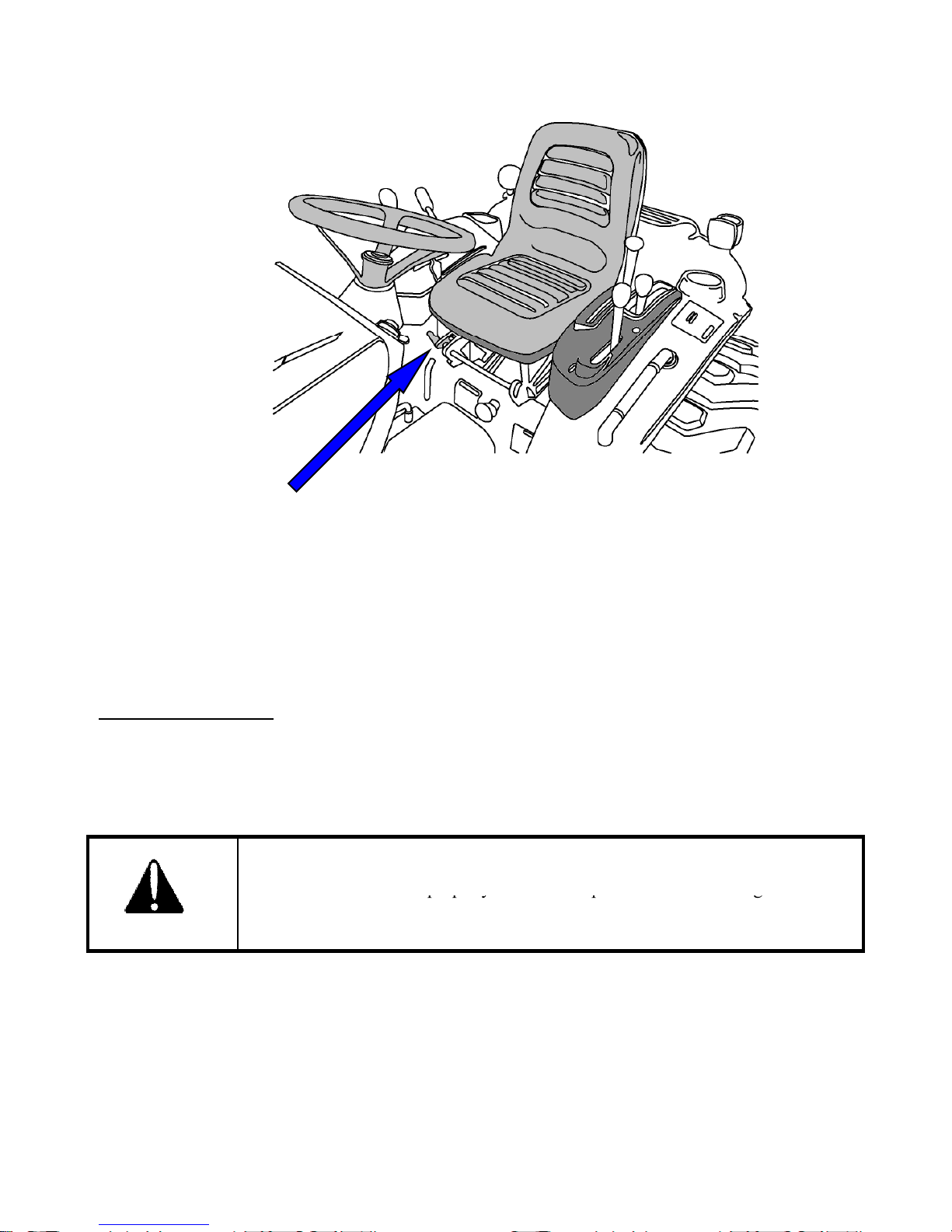
Seat Adjusting Lever
Bef
r
itisi
&
r
pp y p g
NOTE
Do not use solvents to clean the seat. Use warm water with a little detergent added.
ore operating aTracto
mportant to adjust the seat to themostcomfortable position
check whether it is properly locked in its position. Figure 1 identifies the seat fitted to your Tractor.
FOR SLIDING SEAT
To select Seat position, move Adjusting lever and slide Seat closer to or away from Dash panel and
controls.
Check whether the seat properly locked in its position before driving the tracto
DANGER
29
Page 31

SECTION 3
STARTING
THE
ENGINE
39
HYDRAULICS
OPERATION
INSTRUMENT PANEL AND CONTROLS ‥‥‥‥‥‥‥‥‥‥‥‥‥‥‥‥‥‥‥‥ 31
SWITCHES AND GAUGES ‥‥‥‥‥‥‥‥‥‥‥‥‥‥‥‥‥‥‥‥‥‥‥‥‥‥ 31
INDICATOR LAMPS ‥‥‥‥‥‥‥‥‥‥‥‥‥‥‥‥‥‥‥‥‥‥‥‥‥‥‥‥‥ 34
INDEPENDENT PTO ‥‥‥‥‥‥‥‥‥‥‥‥‥‥‥‥‥‥‥‥‥‥‥‥‥‥‥‥‥ 36
TRACTOR CONTROLS ‥‥‥‥‥‥‥‥‥‥‥‥‥‥‥‥‥‥‥‥‥‥‥‥‥‥‥‥ 37
PRE OPERATION CHECK ‥‥‥‥‥‥‥‥‥‥‥‥‥‥‥‥‥‥‥‥‥‥‥‥‥‥ 38
OPERATING THE ENGINE‥‥‥‥‥‥‥‥‥‥‥‥‥‥‥‥‥‥‥‥‥‥‥‥‥‥‥
3 9
‥‥‥‥‥‥‥‥‥‥‥‥‥‥‥‥‥‥‥‥‥‥‥‥‥‥‥
COLD WEATHER STARTING ‥‥‥‥‥‥‥‥‥‥‥‥‥‥‥‥‥‥‥‥‥‥‥‥‥ 43
STOPPING THE ENGINE ‥‥‥‥‥‥‥‥‥‥‥‥‥‥‥‥‥‥‥‥‥‥‥‥‥‥‥ 43
WA R MI N G U P ‥‥‥‥‥‥‥‥‥‥‥‥‥‥‥‥‥‥‥‥‥‥‥‥‥‥‥‥‥‥‥ 44
OPERATING THE TRACTOR‥‥‥‥‥‥‥‥‥‥‥‥‥‥‥‥‥‥‥‥‥‥‥‥‥ 45
DRIVING ‥‥‥‥‥‥‥‥‥‥‥‥‥‥‥‥‥‥‥‥‥‥‥‥‥‥‥‥‥‥‥‥‥‥ 45
STOPPING AND PARKING ‥‥‥‥‥‥‥‥‥‥‥‥‥‥‥‥‥‥‥‥‥‥‥‥‥‥ 46
CONTROLLING ‥‥‥‥‥‥‥‥‥‥‥‥‥‥‥‥‥‥‥‥‥‥‥‥‥‥‥‥‥‥‥ 47
CHECK DURING DRIVING ‥‥‥‥‥‥‥‥‥‥‥‥‥‥‥‥‥‥‥‥‥‥‥‥‥‥ 50
PTO ‥‥‥‥‥‥‥‥‥‥‥‥‥‥‥‥‥‥‥‥‥‥‥‥‥‥‥‥‥‥‥‥‥‥‥‥‥
5 1
REAR PTO ‥‥‥‥‥‥‥‥‥‥‥‥‥‥‥‥‥‥‥‥‥‥‥‥‥‥‥‥‥‥‥‥‥ 51
MID PTO (OPTIONAL) ‥‥‥‥‥‥‥‥‥‥‥‥‥‥‥‥‥‥‥‥‥‥‥‥‥‥‥‥ 52
‥‥‥‥‥‥‥‥‥‥‥‥‥‥‥‥‥‥‥‥‥‥‥‥‥‥‥‥‥‥‥‥
5 3
POSITION CONTROL ‥‥‥‥‥‥‥‥‥‥‥‥‥‥‥‥‥‥‥‥‥‥‥‥‥‥‥‥ 53
LOWERING SPEED CONTROL ‥‥‥‥‥‥‥‥‥‥‥‥‥‥‥‥‥‥‥‥‥‥‥‥ 54
HYDRAULIC OUTLET ‥‥‥‥‥‥‥‥‥‥‥‥‥‥‥‥‥‥‥‥‥‥‥‥‥‥‥‥ 55
HYDRAULIC REMOTE CONTROL VALVE(OPTIONAL) ‥‥‥‥‥‥‥‥‥‥‥‥‥ 56
THREE-POINT HITCH AND DRAWBAR ‥‥‥‥‥‥‥‥‥‥‥‥‥‥‥‥‥‥‥‥ 57
OPERATING 3-POINT LINKAGE ‥‥‥‥‥‥‥‥‥‥‥‥‥‥‥‥‥‥‥‥‥‥‥ 57
TRAILER HITCH ‥‥‥‥‥‥‥‥‥‥‥‥‥‥‥‥‥‥‥‥‥‥‥‥‥‥‥‥‥‥ 59
30
Page 32
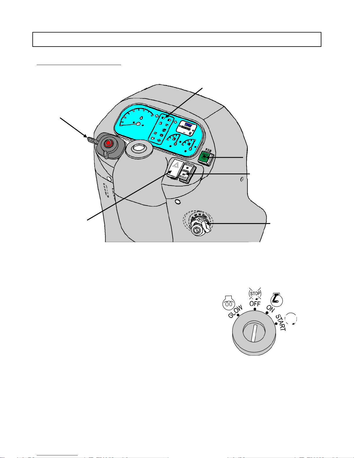
INSTRUMENT PANEL AND CONTROLS
WARNING
『
START
』
The starter motor is engaged. When the
SWITCHES AND GAUGES
LIGHT SWITCH,
INDICATORS AND
HORN
INDICATOR LAMPS
INDEPENDENT PTO
CRUISE CONTROL
SWITCH
HAZARD
LIGHT SWITCH
① KEY SWITCH
『OFF』― The key can be inserted or removed.
『ON』― The electric circuit is on.
『GLOW』― Glow plugs pre-heat the combustion
chamber.
―
key is released it will automatically return
to the 『ON』position
KEY SWITCH
31
Page 33
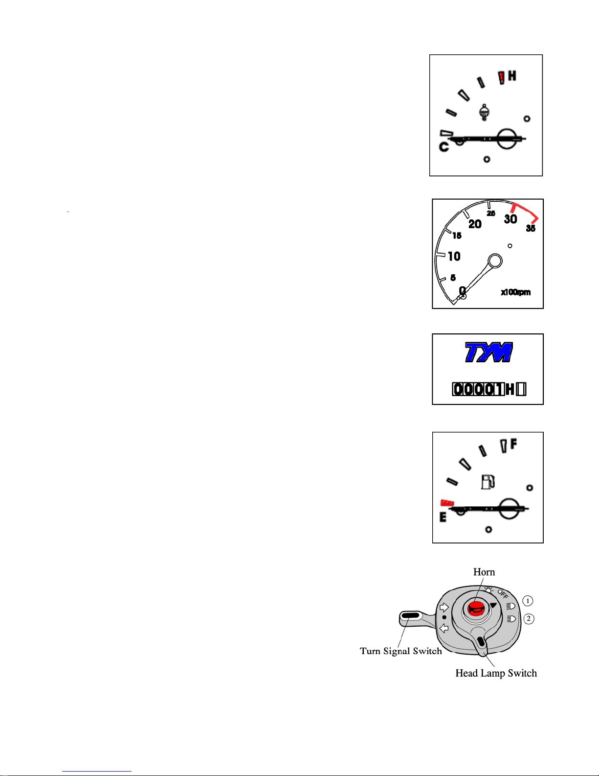
② COOLANT TEMPERATURE GAUGE
③
R
③
1/10th of
⑤
FUEL GAUGE
The gauge shows the coolant temperature with the key switch ON.
C is low to normal temperature and H is high temperature. If the
pointer is in the red H segment the engine is overheating. Refer
thisbookto rectify the problem.
TACHOMETE
This meter shows the revolutions of the engine and the PTO
shafts as well as the travel speed in top gear.
④ HOUR METER
The hour meter consists of digits with the last digit indicating
an hour. It shows hours the tractor has been used.
The lamp at bottom of hour meter should twinkle during
operation
Shows the amount of fuel in the fuel tank when the key switch is
ON.
⑥ LIGHT SWITCH, INDICATORS AND HORN
Head lamp is operated on the main switch.
When indicator is pulled down, left turn signal turns ON and
flashes.
When indicator is pushed up, right turn signal turns ON and
flashes.
When the horn button is pressed, the horn will sound.
32
Page 34
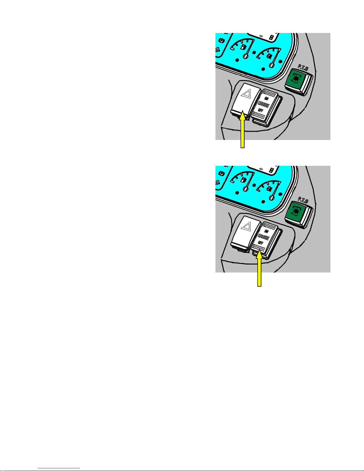
⑦ HAZARD WARNING LIGHT SWITCH
Wh
When the switch is pushed once, the hazard warning
lights(left and right turn signal) are ON and flash.
en the switch is pushed again, the hazard lights are
OFF.
⑧ CRUISE CONTROL SWITCH
When the switch is pushed ON Position, the cruise
control is engaged and the switch light and indicator
lamp on instrument panel are ON.
When the switch is pushed OFF Position or brake pedal
is depressed, the cruise control and the lights are OFF.
HAZARD WARNING LIGHT SWITCH
CRUISE CONTROL SWITCH
33
Page 35
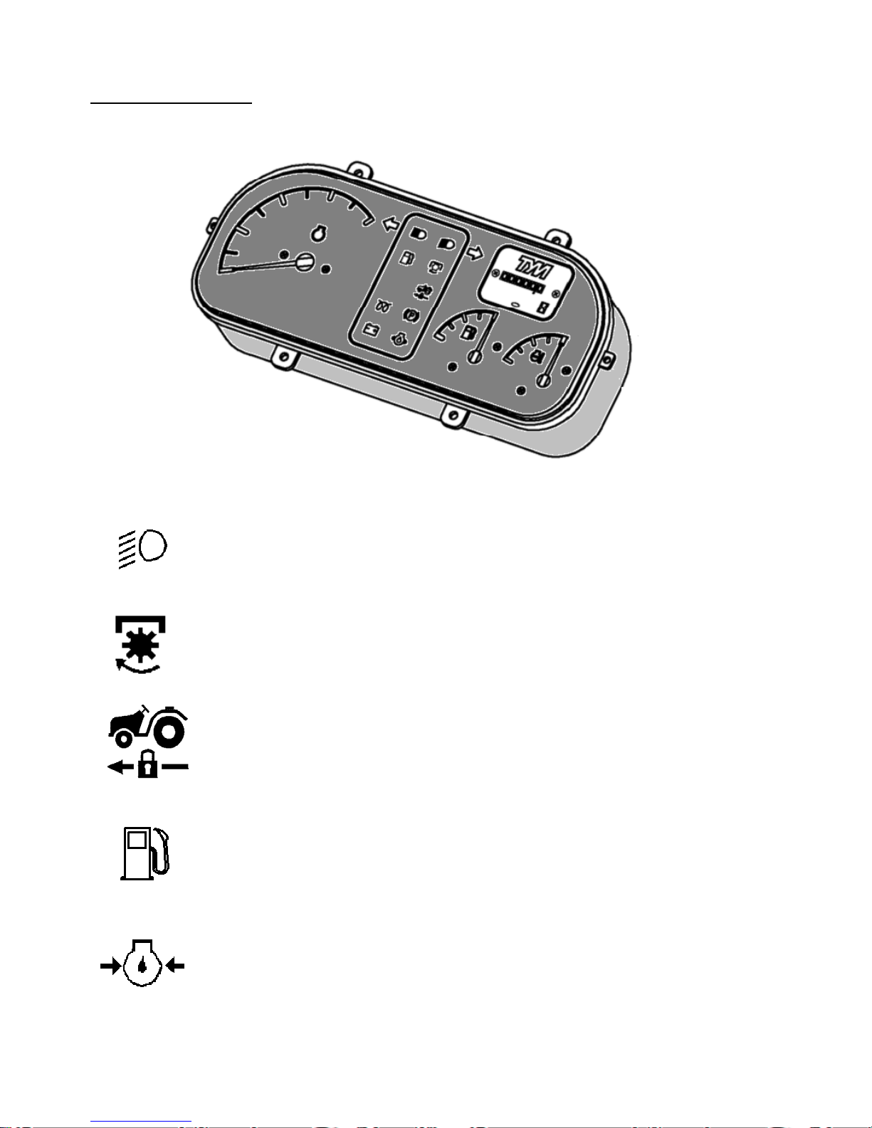
INDICATOR LAMPS
① Low beam lamp
This lamp is operated on the combination switch
② PTO Monitor Lamp
This lamp will turn on when PTO clutch is engaged.
③ Cruise Control Lamp
This lamp will turn on when cruise control is engaged.
④ Fuel Empty Warning Lamp
This lamp shows warning that the fuel in fuel tank goes empty. If this lamp
comes on, Fill the tank with fuel.
⑤ Oil pressure lamp
This lamp will go out as soon as the engine starts if the oil pressure is correct. If
it comes on while the engine is running, stop the engine and get expert advice.
34
Page 36

⑥ Charge lamp
This lamp will go off as soon as the engine starts to run to indicate that the
alternator is charging (Please note, as broken fan belt can cause the light to
come on, please stop the engine as overheating can occur if not rectified
immediately).
⑦ Glow signal Lamp
This lamp indicates pre-heating.
⑧ Turn Signal Lamp
These lamps are used to indicate operator’s turn direction.
When indicator is pulled down, left turn signal turns ON and flashes.
When indicator is pushed up, right turn signal turns ON and flashes.
These lamps will turn on and flash when hazard waning switch is pushed.
35
Page 37
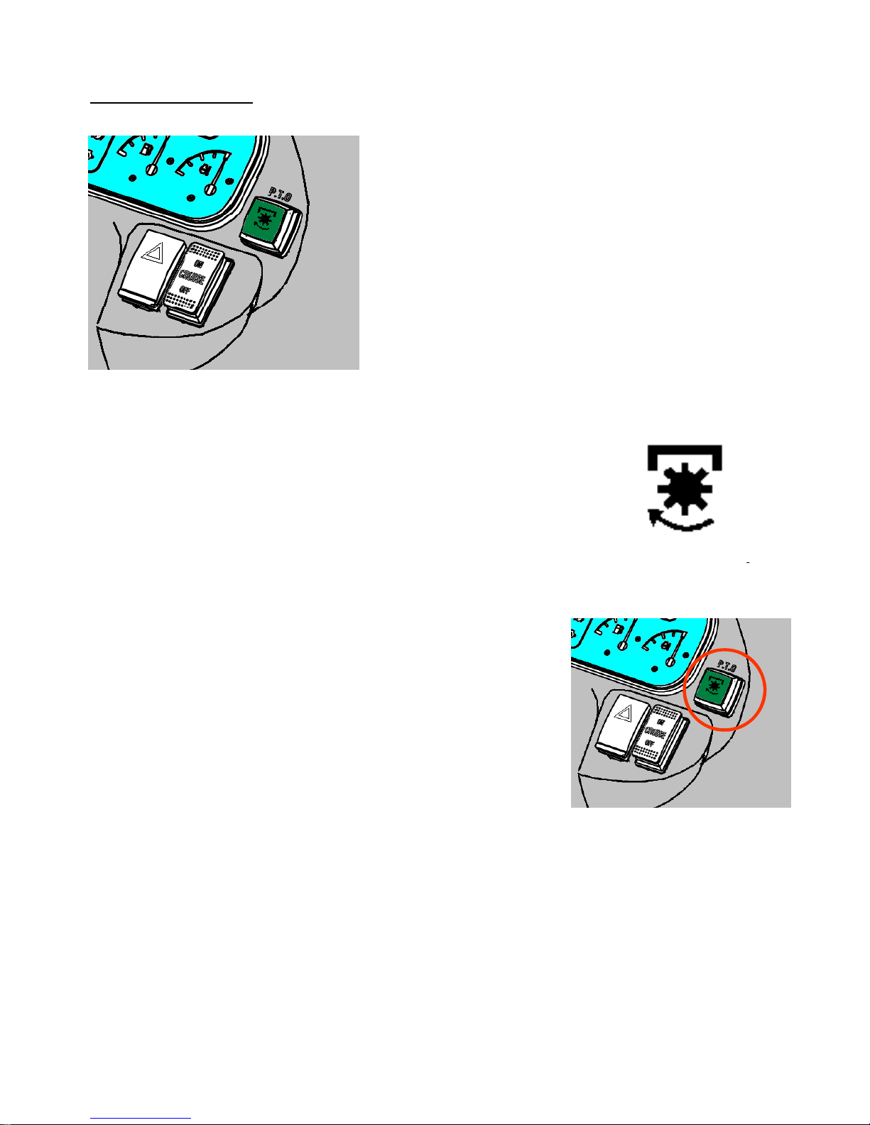
INDEPENDENT PTO
p
p
■ The PTO monitor lamp
On the dash panel indicates the state of the PTO shaft.
1. If the monitor glows: The PTO is On.
2. If the monitor is off: The PTO is off
■ PTO ON/OFF Switch
PTO ON/OFF switch is situated on the right hand side on the
instrument panel and can be identified easily with its built in
green colored indicator. When the switch is pushed down to start
the PTO indicator glows to indicate that the switch and the PTO
are in ON position, If the switch is pushed down again the
indicator goes off signaling that the PTO is OFF.
The PTO shaft will not rotate if switch is in OFF position.
PTO monitor Lam
PTO ON,Off switch
36
Page 38
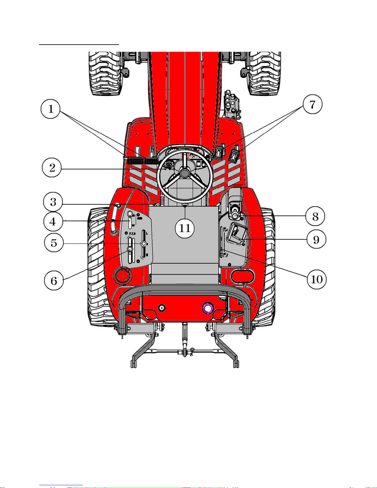
TRACTOR CONTROLS
① Turn Brake Pedals ② Parking Brake Lever ③ Differential Lock Pedal
④ Front Wheel Drive(4WD) Lever ⑤ Range Shift Lever ⑥ PTO Lever
⑦ Speed Control Pedals ⑧ Joy stick Lever ⑨ Hand Throttle Lever
⑩ Position Control Lever ⑪ Lowering Speed Control knob
37
Page 39
PRE-OPERATION CHECK
p,p
To avoid problems, it is recommended that a range of checks be carried out daily before starting the
tractor. For details of the items and period, please refer to the maintenance table.
1. Check all shields and guards. Be sure them are in place.
2. Check the engine coolant level. Add if required.
3. Check the engine oil level. Add if required.
4. Check the transmission oil level. Add if required.
5. Check the tire pressure. Adjust if required.
6. Check the fuel level with key switch ON position. Refuel if required.
7. Check the operation of all gauges, switches, lights, indicators and horn.
8. Check the brake pedals. Adjust if required
9. Check the speed control pedals.
10. Check the seat belt and ROPS.
CAUTION
To avoid injury, always ensure that the tractor is on level place with the engine
stop and the parking brake is engaged before check.
38
Page 40
STARTING THE ENGINE
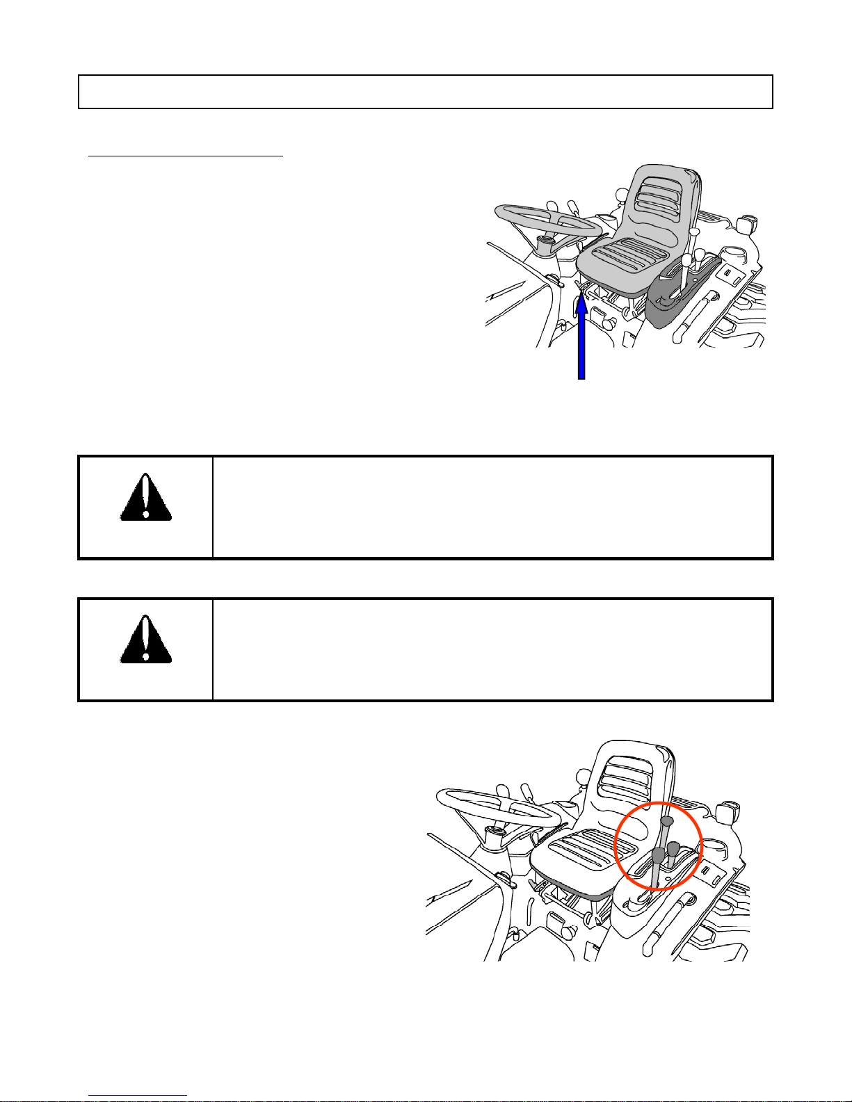
1.Sit
Adjust
lt
OPERATING THE ENGINE
on the operator seat.
seat and seat be
■ Adjusting Operator Seat
It is important to adjust the seat to the most comfortable
position.
① Lift the adjust lever at the front of the seat
② Slide the seat forward or backward to desired position.
③ Release the lever. Then the seat will lock automatically
in position
To avoid injury, always use the seat belt when the tractor is equipped with
ROPS.
CAUTION
Do not use the seat belt if the ROPS is removed
Seat Adjusting Lever
To avoid injury, ensure that the steering wheel is locked before operating the
tractor.
CAUTION
2. Make sure that all levers are in their neutral
position - the range shift lever, the rear PTO
lever, mid PTO lever and front wheel drive
lever.
39
Page 41

3. Push the hydraulic lever in the down position.
yyp
4. Pull the hand throttle lever to about 1/3~1/2 way.
■ Hand Throttle Lever
The hand throttle lever is used to change engine speed.
Pulling the throttle lever toward the operator decreases
engine speed.
Pushing it away from the operator increases engine
speed.
5. Insert the key. Turn the key “ON” position. Do not start
engine.
6. Make sure that the PTO switch is off. It is allowable that
either of PTO is off. Refer to above independent PTO.
7. Ensure that the warning lights are working
40
Page 42
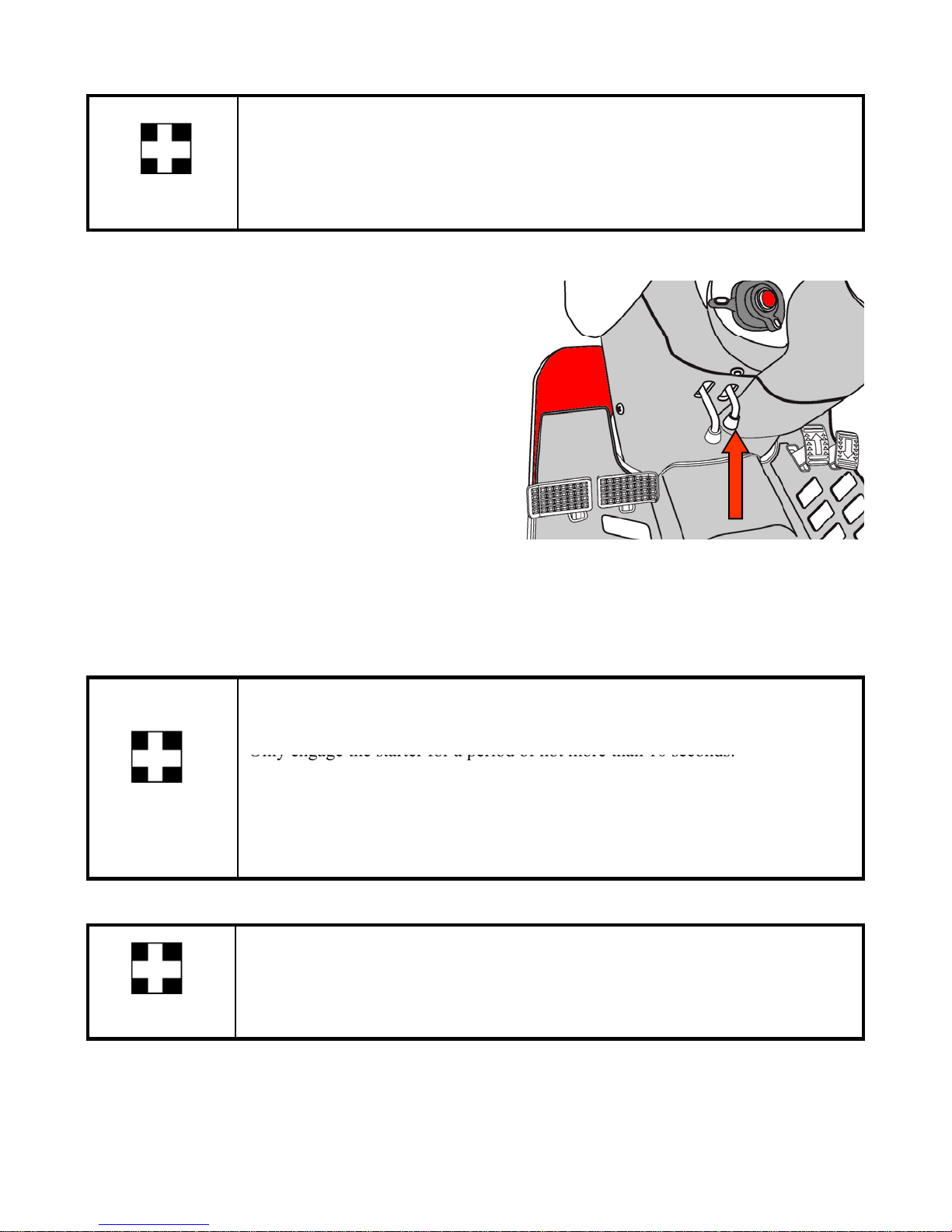
■ Safety Start Conditions
Only engage the starter for a period of not more than 10 seconds.
Engine will start only under conditions as follows;
① PTO switch is OFF.
IMPORTANT
② Brake is depressed or parking brake is engaged.
8. Depress the master brake pedal fully or make sure
the parking brake is engaged.
■ Engaging Parking Brake
① Depress the brake fully.
② Pull up the parking brake lever to engage.
③ Depress the brake again to release the parking brake.
9. Turn the key to “START” position and release when the engine starts.
10. Ensure that all warning lights are off with the engine running.
Never turn the key to the start position while the engine is running as this can
cause serious damage to the starter and engine flywheel.
If Engine does not start, rest the starter for about 20 seconds and try again for a
maximum of 10 seconds.
IMPORTANT
If the engine does not start after repeated attempts, refer to the troubleshooting
guide.
Especially in cold weather, always allow the tractor to idle for a while to warm
up and build up sufficient oil pressure to ensure normal operating temperature
for longer engine life.
IMPORTANT
41
Page 43

9. Turn the key to “START” position and release when the engine starts.
Especially
in
cold
weather
always
allow
the
tractor
to
idle
forawhile
to
warm
10. Ensure that all warning lights are off with the engine running.
Never turn the key to the start position while the engine is running as this can
cause serious damage to the starter and engine flywheel.
Only engage the starter for a period of not more than 10 seconds.
If Engine does not start, rest the starter for about 20 seconds and try again for a
maximum of 10 seconds.
IMPORTANT
If the engine does not start after repeated attempts, refer to the troubleshooting
guide.
,
up and build up sufficient oil pressure to ensure normal operating temperature
for longer engine life.
IMPORTANT
42
Page 44
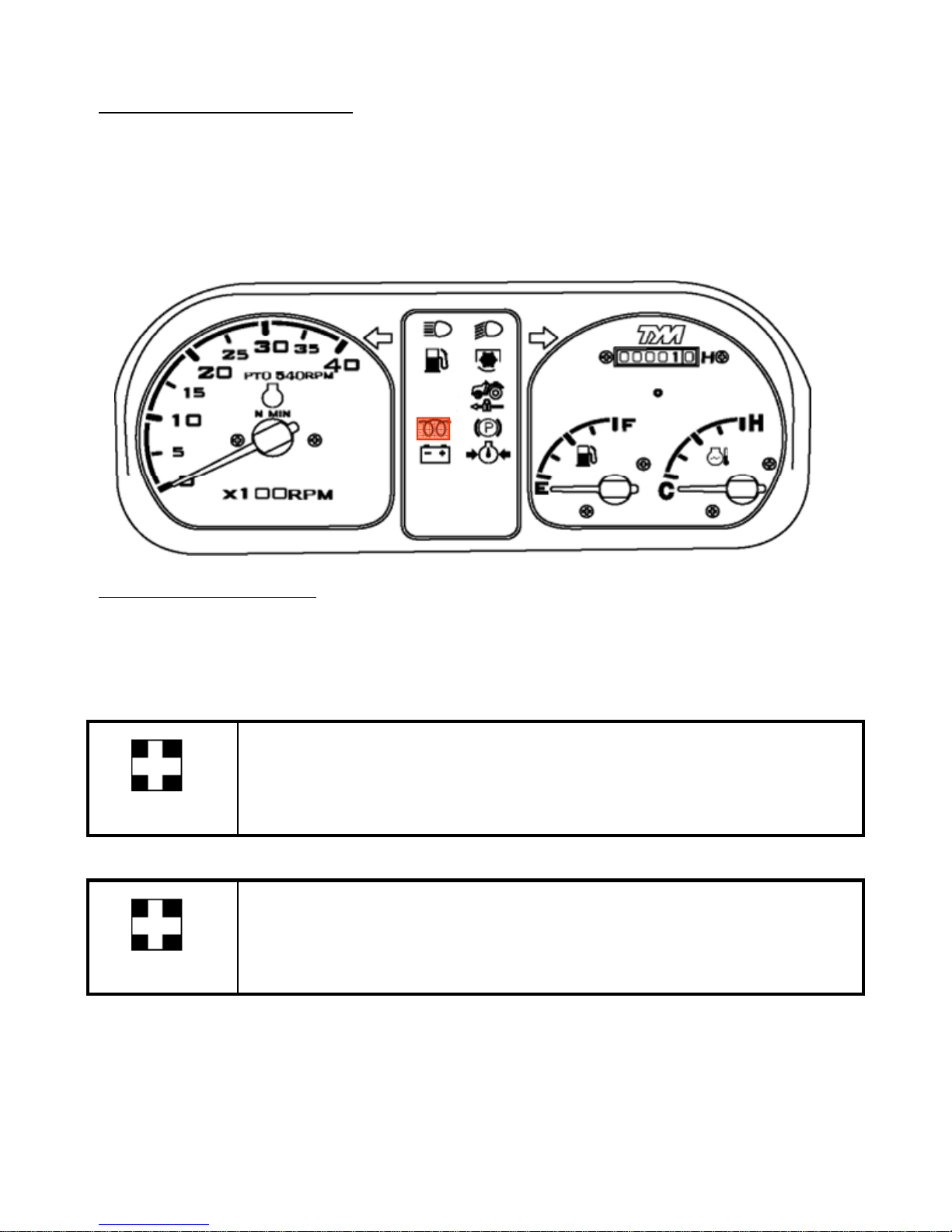
COLD WEATHER STARTING
Turn the key to left to glow position for a moment and release it. The automatic heater will start
When the ambient temperature is below –5Ԩ(23Ԭ), the following step is to be used instead of step
10.
working as will be indicated by a light on the instrument panel. As the lamp goes off, turn the key to
the start position to start the engine.
STOPPING THE ENGINE
1. Let the engine idle forapproximately 2 minutes andturn key switch to off position.
2. The engine stops when the key is turned off.
3. Remove key
After long or heavy work allow the engine to idle for 5- 10 minutes and turn
the key off.
IMPORTANT
If the engine does not stop by key, consult immediately your Dealer/Distributor.
IMPORTANT
43
Page 45
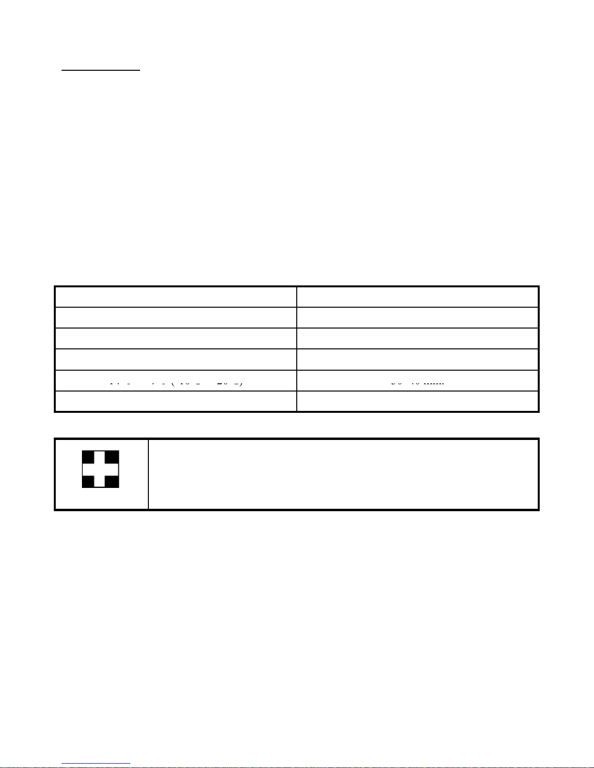
WARMING UP
Failure to do so can shorten engine life substantially
Temperature
Time for warming up
14
Ԭ
Ԭ
(
10Ԩ20Ԩ)3040 min.
E
d
When starting the engine allow it to warm up to operating temperature by allowing it to idle 5-10
minutes to ensure full lubrication and operating temperature.
.
■ Warming up in Cold Weather
Cold weather will change the viscosity of the oil, resulting in a reduced oil pumping capacity, which
can cause damage to the engine if it is not warmed up correctly.
It also causes problems with the hydraulic system and the synchromesh in the transmission.
Correct times for warming up are:
Above 50Ԭ (10Ԩ) 5~10 min.
50 Ԭ ~ 32 Ԭ (10Ԩ ~0Ԩ) 10~20 min.
32 Ԭ ~ 14 Ԭ (0Ԩ ~-10Ԩ) 20~30 min.
IMPORTANT
~-
4
-
-
Below -4 Ԭ (-20Ԩ) Over 40 min.
nsure the parking brake is on during the warming perio
44
Page 46
OPERATING THE TRACTOR
-
Sufficient engine warm up
pg g
completely
When the engine warm up correctly, the tractor is prepared for operating.
DRIVING
1. Make sure that all condition is ready.
Adjustments of the operator seat, the seat belt, and the
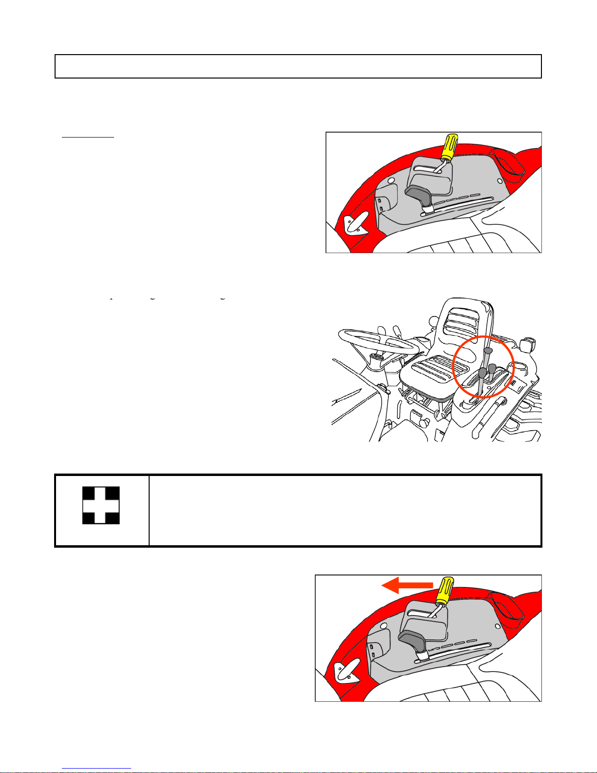
steering wheel.
- Fasten seat belt
2. Raise the implement using the position control
lever.
3. Select speed range with the range shift lever.
■ Range Shift Lever
The range shift lever is used to select the speed range
of tractor.
The lever can be shifted only when the tractor stops
.
The lever is linear and has three positions, a neutral
and two range gears. A neutral is located between L
and H range gear.
Do not operate the range shift lever without stopping the tractor.
IMPORTANT
4. Increase the engine speed with hand throttle.
45
Page 47
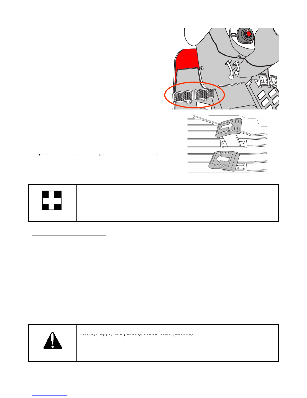
5. Release the parking brake by depressing the brake.
6
Depress the reverse control pedal to move backward.
gy
1. Release speed control pedals. Depress the brake pedal to
Always apply the parking brake when parking.
. Select the driving direction and depress speed control
pedal.
■ Speed Control Pedals
Depress the forward speed control pedal to move forward.
The speed control pedal will return in neutral position and
the tractor will stop when the speed control pedal is
released.
Do not change from forward to backward or backward to forward suddenly in
high range. Sudden change may result in damage of mechanism and place the
operator at risk of injury
IMPORTANT
STOPPING AND PARKING
stop the tractor, if necessary.
2. Decrease the engine speed using hand throttle.
3. Move the range shift lever to neutral position.
4. Lower any implement to the ground.
5. Apply the parking brake.
6. Turn the key to OFF position to stop the engine.
7. Remove the key.
Failure to do so can cause accidents and damage.
As an extra precaution when parking on a slope, chock the rear wheels.
CAUTION
46
Page 48
CONTROLLING
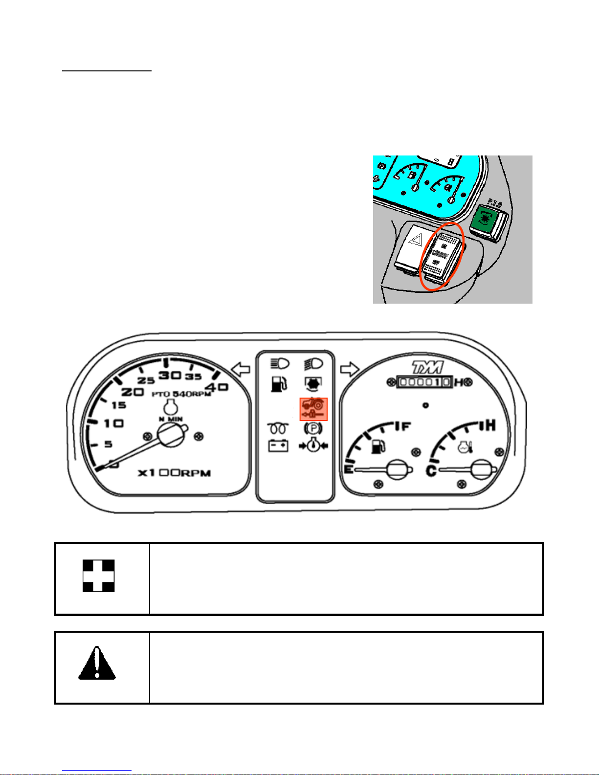
control is engaged, the cruise control lamp on instrument panel will turn on
■ Cruise Control
The cruise control function is provided for comfortable and efficient operation. When the cruise
.
1.Engaging the cruise control.
① Depress the forward speed control pedal till getting
desired speed.
② Push the cruise control switch to engage cruise control
③ Release the speed control pedal
2. Disengaging the cruise control
There are two methods to disengage the cruise control.
① Push cruise control switch “OFF” or,
② Depress the brake pedal.
To avoid damage of mechanism, do not depress both of the speed control pedals
when the cruise control is engaged.
IMPORTANT
To avoid personnel injury, do not use the cruise control in reverse.
CAUTION
47
Page 49
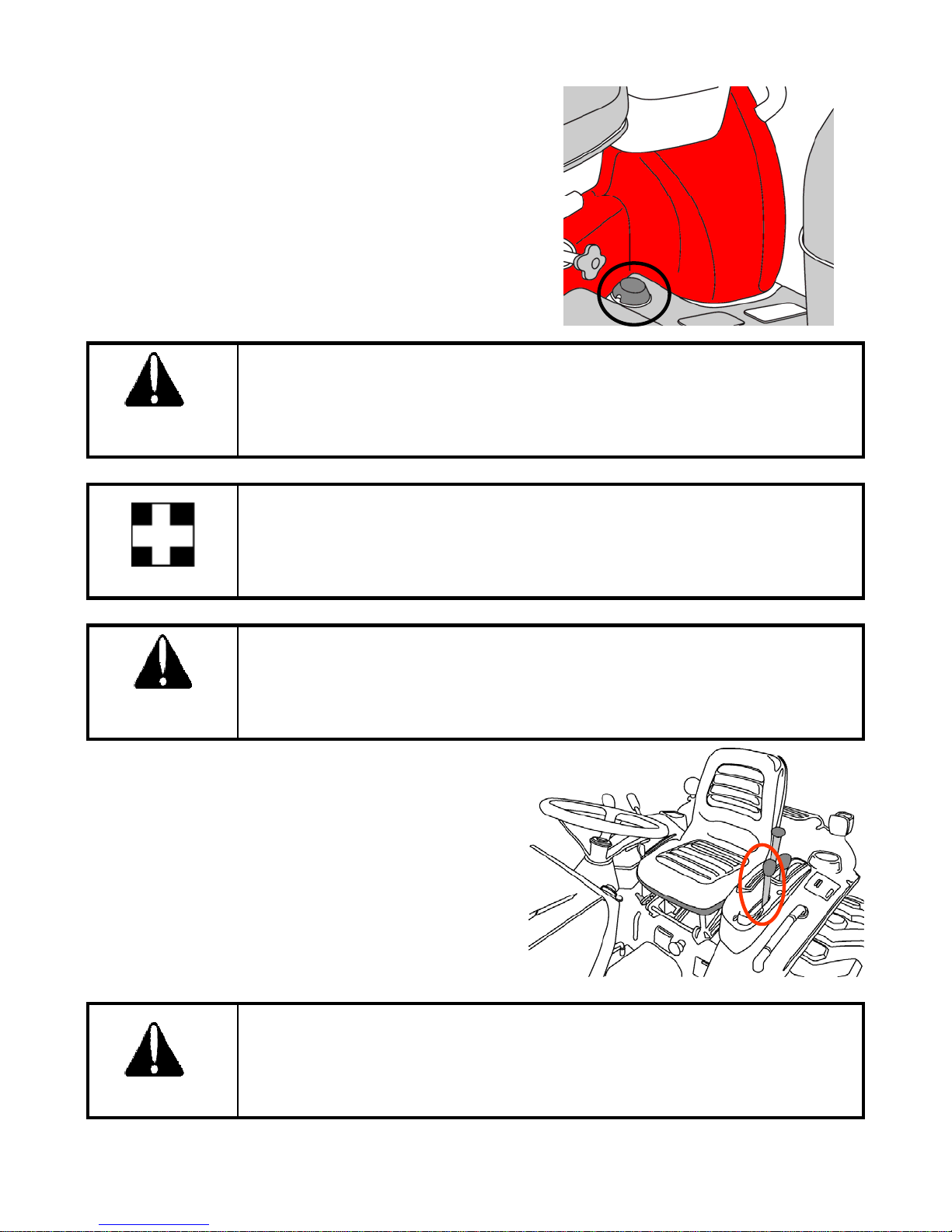
■ Diff-lock Pedal
To release it remove the foot from the pedal
In case of wheel slippage ,use the diff-lock by pushing
down on the diff lock pedal.
.
Tractor will be difficult to turn if the Diff-lock is engaged, ensure the lock is
disengaged before turning the steering wheel.
DANGER
Do not use high engine speed when engaging differential lock. If the differential
lock does not release after removing the foot from the differential lock pedal
alternatively brake with the left and right turn brake until it gets released.
IMPORTANT
Never use the differential lock at high speed or on the road as this can cause roll
over and injury.
CAUTION
■ Front Wheel Drive(4WD)
The front wheel drive is used to increase traction
performance greatly by engaging the front wheel. The
front wheel drive can be engaged when the tractor is
stopped.
In the ON position of the front wheel drive lever, the
front wheels are engaged and in the OFF position,
they are disengaged.
Do not use front wheel drive at high speed or on the road as premature wear of
components will result.
CAUTION
48
Page 50
■ Light Turns in the Field
U
bili
hill
When towing trailers in hilly terrain ensure that they are equipped with brakes,
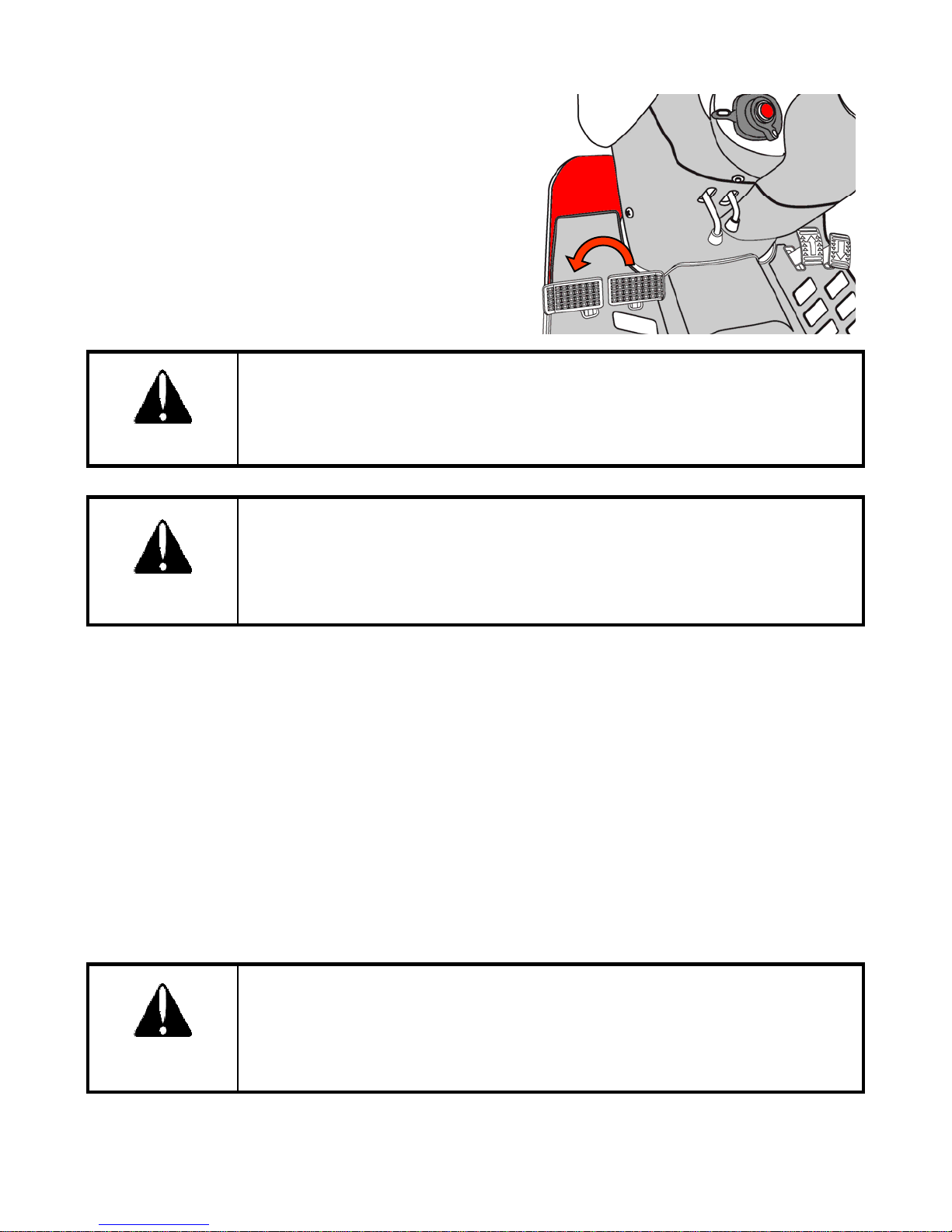
To make a tight turn at low speed, use both the steering
wheel and the turn brake pedal at the same time. For left
turn, use the left turn brake pedal and for right turn, use
the right turn brake pedal.
Perform tight turns only at a slow safe speed.
Doing so at a high speed can cause rollovers and very serious injury or death.
CAUTION
Do not use the turn brake pedals for high speed or road use. In the interest of
safety always use it on the road or at high speed as using one side only can
cause rollovers.
When servicing the tractor ensure that the adjustment on both sides in the
WA R N I NG
same.
■ Uphill Start on a Steep Slope
1. Depress the brake pedal.
2. Set the range shift lever to Low and the hand throttle to medium engine speed.
3. Release the brake pedal.
4. Depress the speed control pedal slowly.
5. Adjust the hand throttle to the desired speed .
■ Driving Downhill
se the engine’s a
ty to brake when traveling down
.
Never rely on the brakes only and never travel downhill with the gears in neutral.
When operating in hilly terrain the risk of the rollover is increased substantially,
please drive with extra care.
use a lower gear to get maximum engine braking and do not change gears on a
CAUTION
down hill run.
49
Page 51
CHECK DURING DRIVING
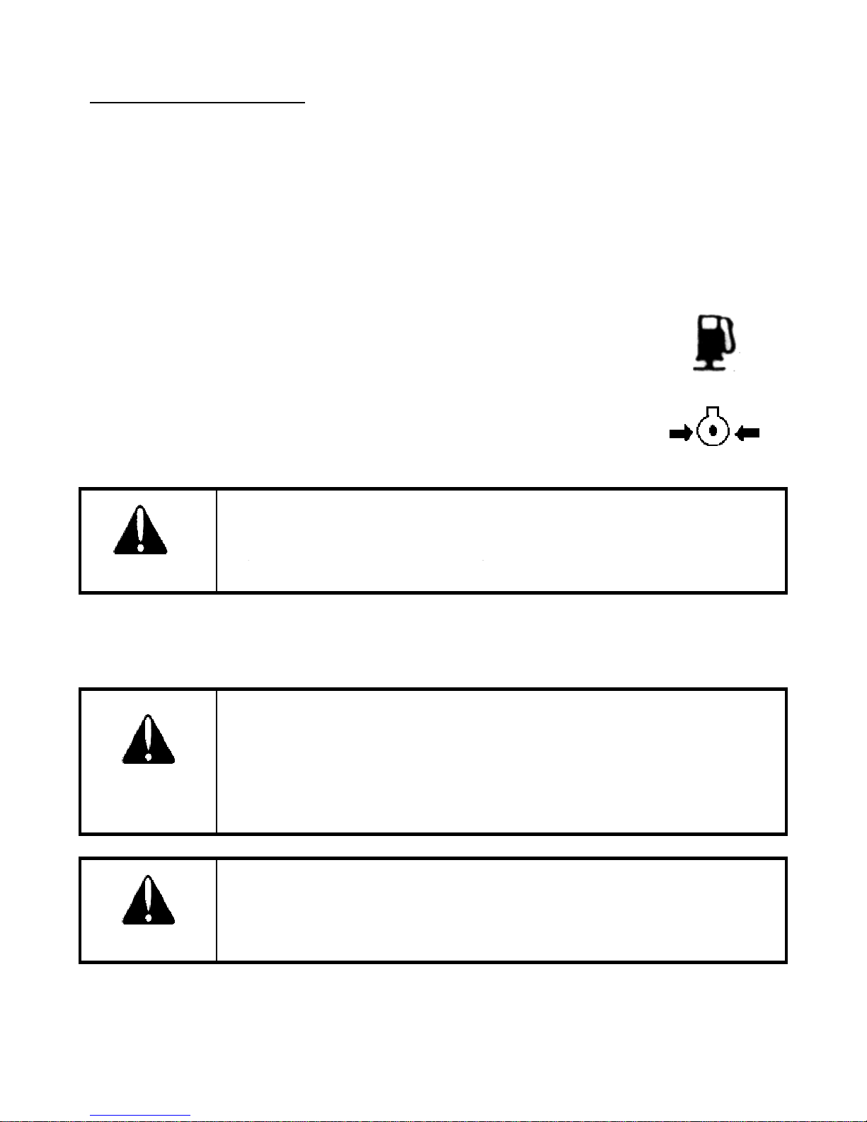
If the oil pressure lamp turns on, check the oil level first of all. If the oil level is OK ask a qualified
If th
yg
Strictly follow the l
l traffic
CAUTION
Constantly monitor the warning lamps on the instrument panel and if any comes on stop the tractor
to determine the cause.
dealer to check the reason for the light coming on.
If the charge lamp turns on, check all connections and ensure that the fan belt is not broken. If all
connections and the fan belt are intact, consult your dealer to determine the cause of the problem.
■ Fuel Gauge
To avoid excessive condensation in the fuel tank, refill at the end of each day’s
work and ensure during the day that it does not drop to a low level where the
fuel system will require bleeding to expel air in the system after refilling the
tank.
■ Engine Coolant
e gauge indicates that the engine is running hot, stop the tractor and check
the coolant in the radiator.
Allow the engine to cool down before opening radiator cap as serious burns
may result due to hot steam & boiling water.
DANGER
Also check to ensure that the fins in the radiator core are not clogged or that the tractor has a
broken or stretched fan belt.
When traveling on public or farm roads connect both brake pedals and allow
for the weight of any mounted implement to ensure that the unit is not
unbalanced.
Also allow for the width when passing other road users.
CAUTION
Where fitted use the hazard lights provided.
oca
regulations.
When operating near others with an implement attached take particular care to
allow for the width of the implement and avoid accidents.
50
Page 52
PTO
or separately at same time
REAR
PTO
OFF
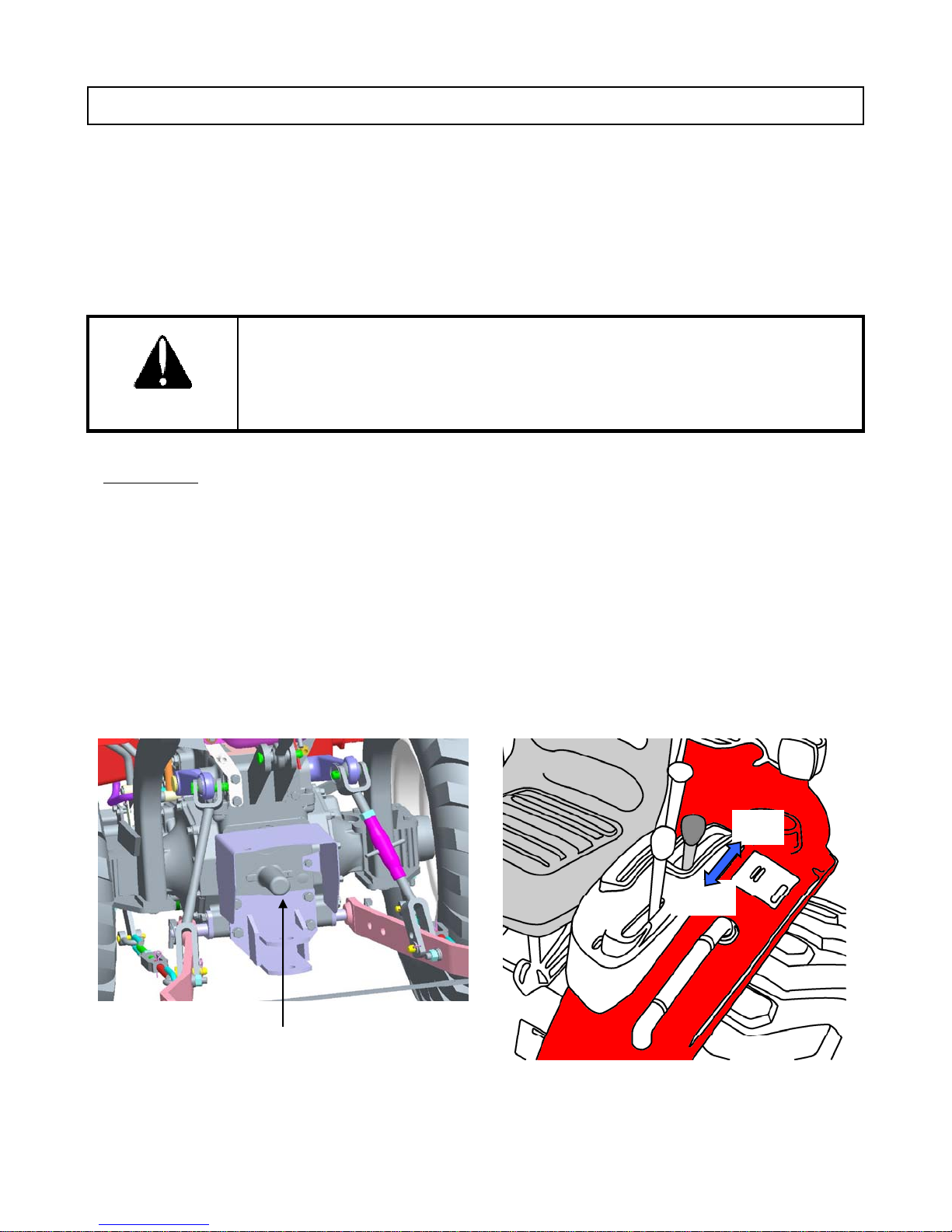
Both of the rear and mid PTO are provided for variable utility. They can be engaged simultaneously
.
The engine will not start if PTO switch is ON position.
The engine will shutoff if the operator leaves the seat with parking brake released and PTO engaged
To avoid damage of transmission and implement, do not engage PTO with
the engine running at high speed.
CAUTION
The tractor has one speed PTO(540rpm). Use the PTO lever to engage. The PTO switch must be
OFF before PTO is engaged.
1. Decrease engine speed to near idle.
2. Make sure that PTO switch is OFF.
3. Engage rear PTO using the PTO lever.
4. Turn on the PTO switch.
5. Increase engine speed to desired speed.
ON
PTO safety cover
51
Page 53
MID PTO(OPTIONAL)
5. T
PTO
IMPORTANT
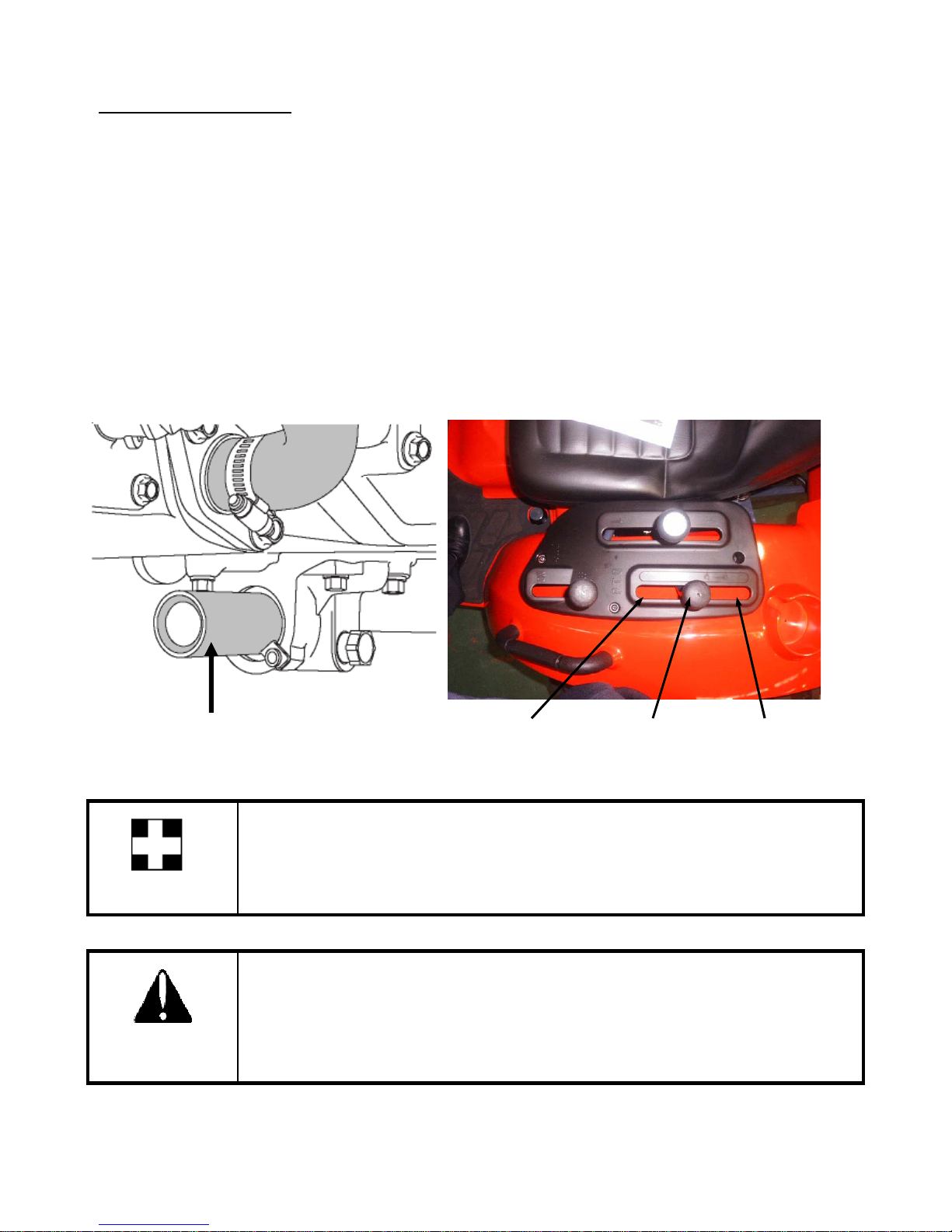
The speed of mid PTO is 2,000rpm. Use the PTO lever to engage. The PTO switch must be OFF
before PTO is engaged.
1. Decrease engine speed to near idle.
2. Make sure that PTO switch is OFF.
3. Engage mid PTO using the PTO lever.
4. If rear PTO is needed to engage, shift the PTO lever to correct position.
urn on the
switch.
6. Increase engine speed to desired speed.
Mid PTO safety cover
Mid Mid + Rear Rear
If operator turns off PTO switch, rear PTO and mid PTO are off at once.
Do not operate any implement at a high speed than is specified for it.
When making adjustments to the implement stop the engine to avoid serious
injury.
CAUTION
When leaving the tractor stop the engine, and remove the key. Set the parking
brake.
52
Page 54
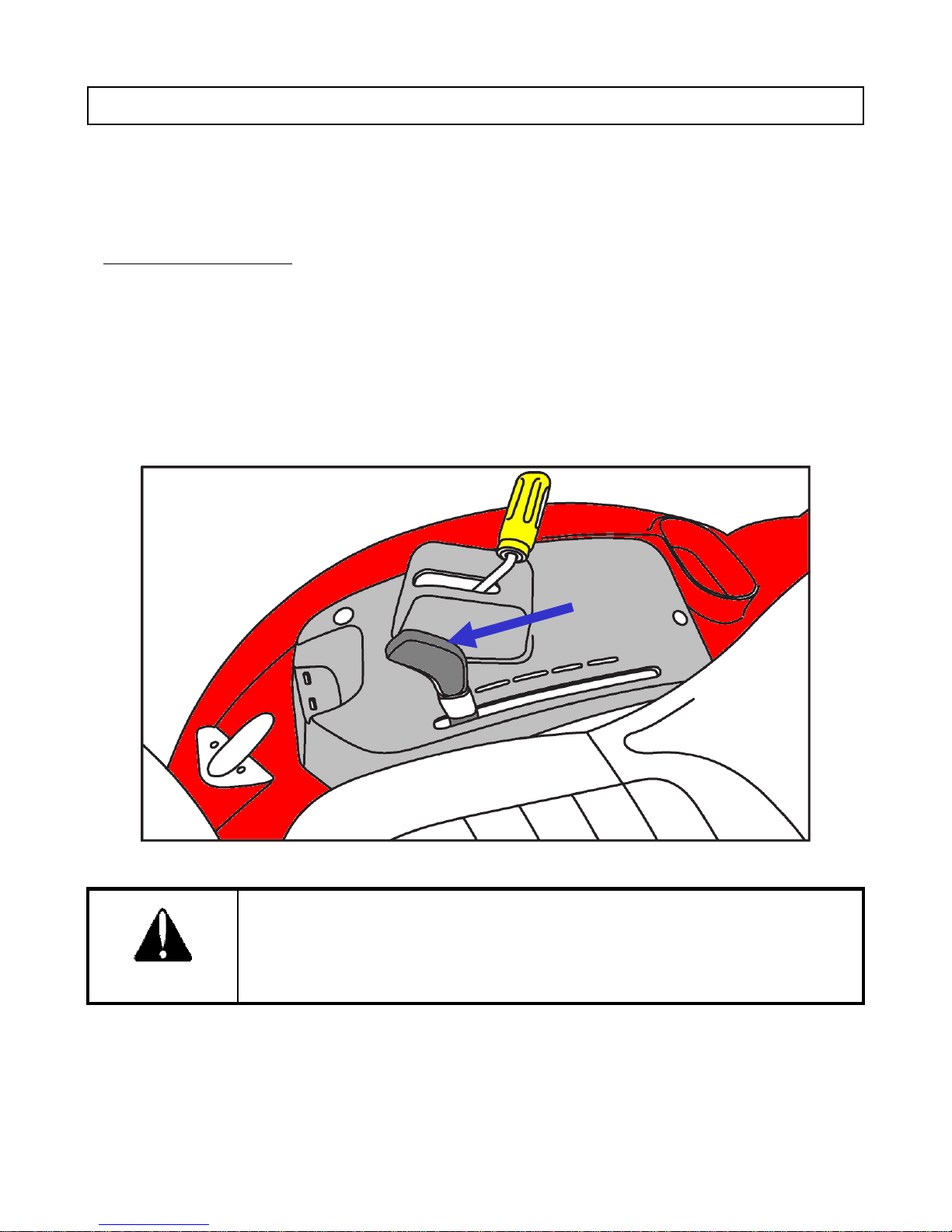
HYDRAULICS
The hydraulics are powered with an engine driven hydraulic pump and controlled with a position
control lever mounted beside the driver.
POSITION CONTROL
Implements can be raised and lowered with the hydraulic position control lever and can be stopped
at any position by stopping the lever.
To ensure a consistent working depth the adjustable stop can be set to ensure that the implement
returns to the same depth every time.
To raise the implement : Pull the lever back
To lower the implement : Push the lever forward
After finishing the work, always lower the implement to the ground and switch
off the engine, Set the parking brake to avoid injuries and accidents.
CAUTION
53
Page 55
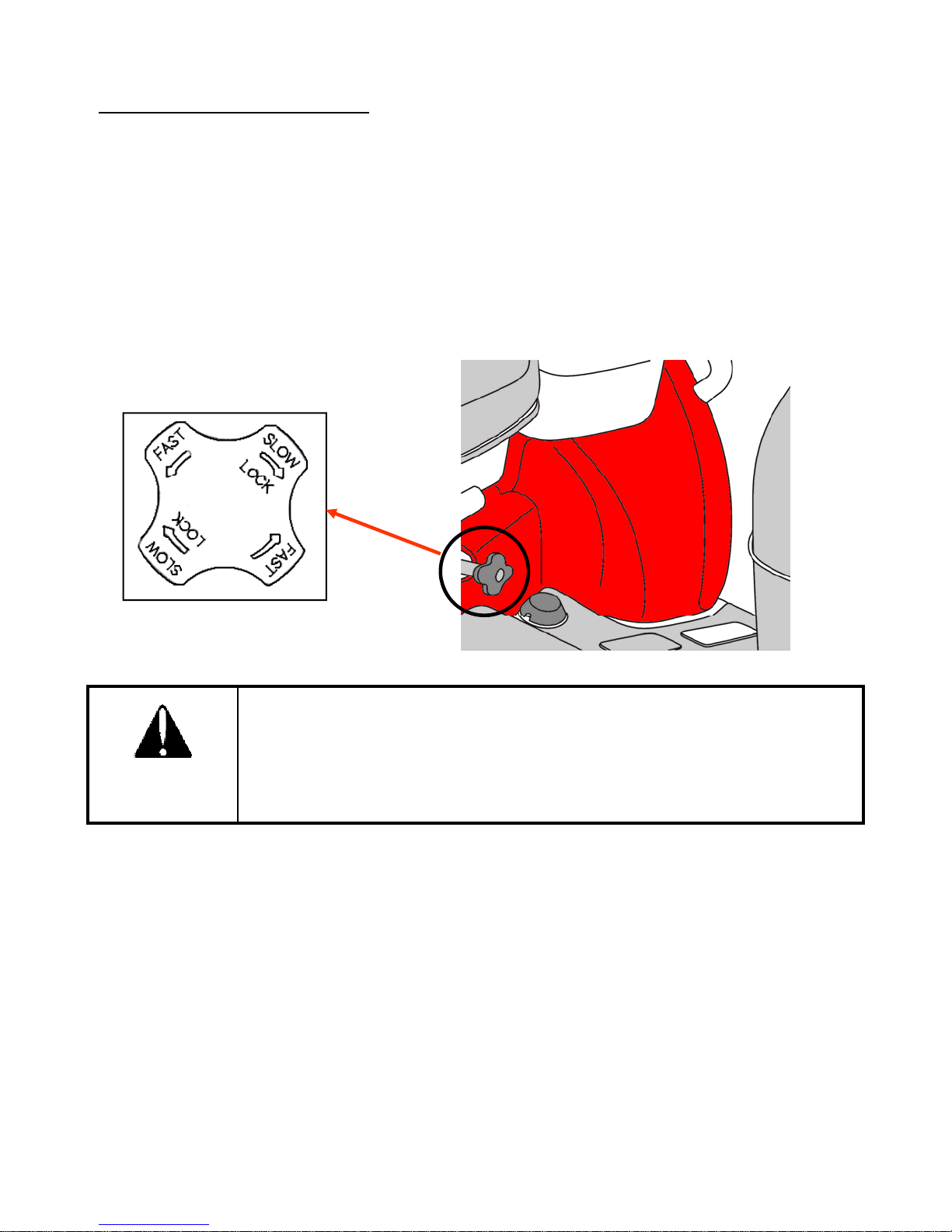
LOWERING SPEED CONTROL
2. Replacing tires or blades on an implement
To adjust the lowering speed for three point hitch, use the lowering speed control knob. The knob
controls the downward speed of the hydraulics three point hitch and is positioned at the front of the
operator seat.
To slow the downward speed- Turn the knob clockwise
To increase the downward speed, turn the knob anticlockwise.
To lock, turn the knob clockwise.
Do not over tighten the knob.
CAUTION
Always set the knob to lock when
1. Traveling on the road
.
3. Making adjustments to an implement. Sudden dropping of an implement due
to hydraulic problems can cause serious injury or death.
54
Page 56
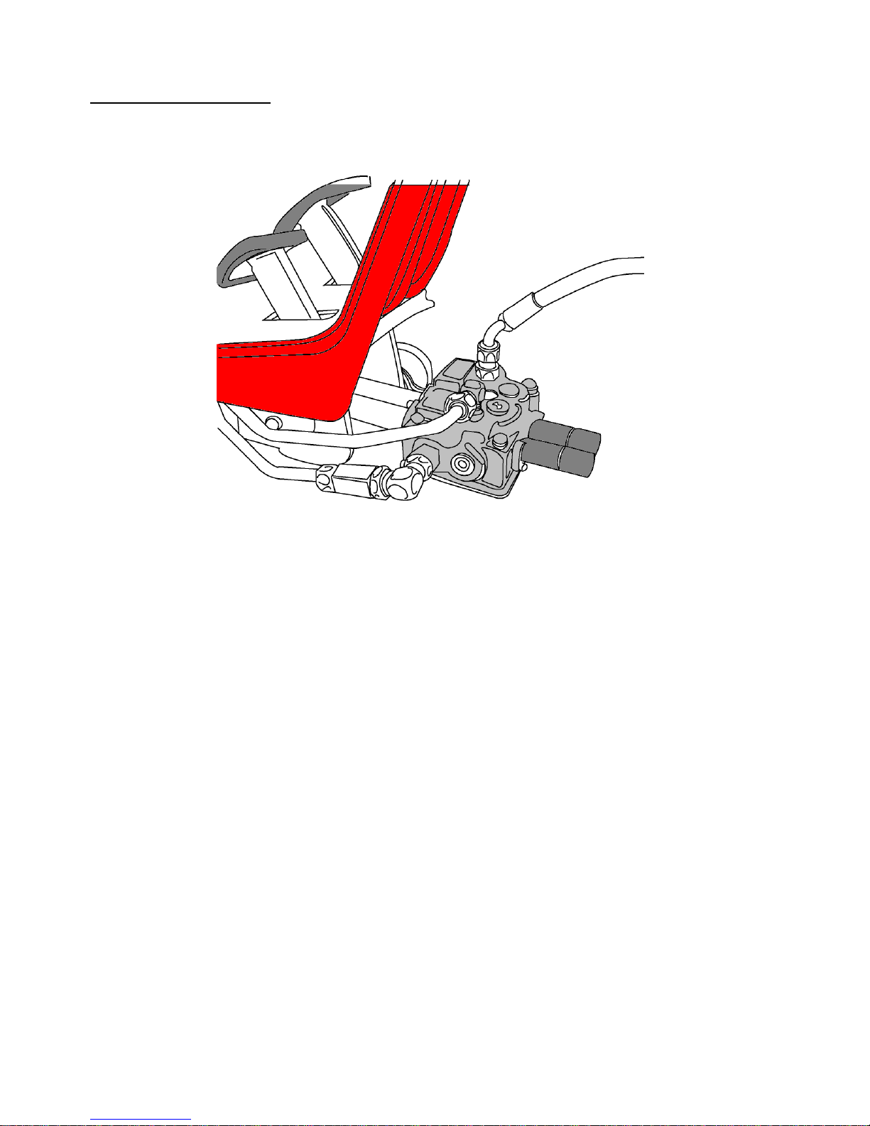
HYDRAULIC OUTLET
■
Detaching the Loader
The tractor is equipped the hydraulic outlet for attaching the hydraulically driven implement such as
front end loader. The hydraulic outlet is located on right hand side of transmission
■ Installing the Loader
1. Connect the front end loader hoses to ports of loader control valve(A1, B1, A2, and B2).
2. A1 and B1 ports are used for lift/lowering/floating functions (inner side).
3. A2 and B2 ports are used for bucket/regenerative functions (outer side).
1. Lock the joystick lever with the lever front of joystick.
2. Detach the hydraulic hoses of loader
3. Assemble the steel cap (PF-3/8) on valve.
55
Page 57
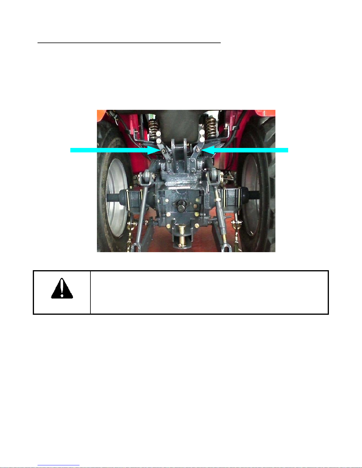
HYDRAULIC REMOTE CONTROL VALVE (OPTIONAL)
The outlets have male threaded
In case, do not use the remote control valve
The hydraulic remote control valve can be equipped as option. The valve is used when attaching the
implement operated by hydraulic cylinder.
.
Use the remote control lever to operate implement. Move the lever up or down to control implement.
CAUTION
Make sure that Remote Control Valve Lever should be in neutral position
.
Failure to follow this instruction can result in serious damage of hydraulic
Components and engine.
56
Page 58
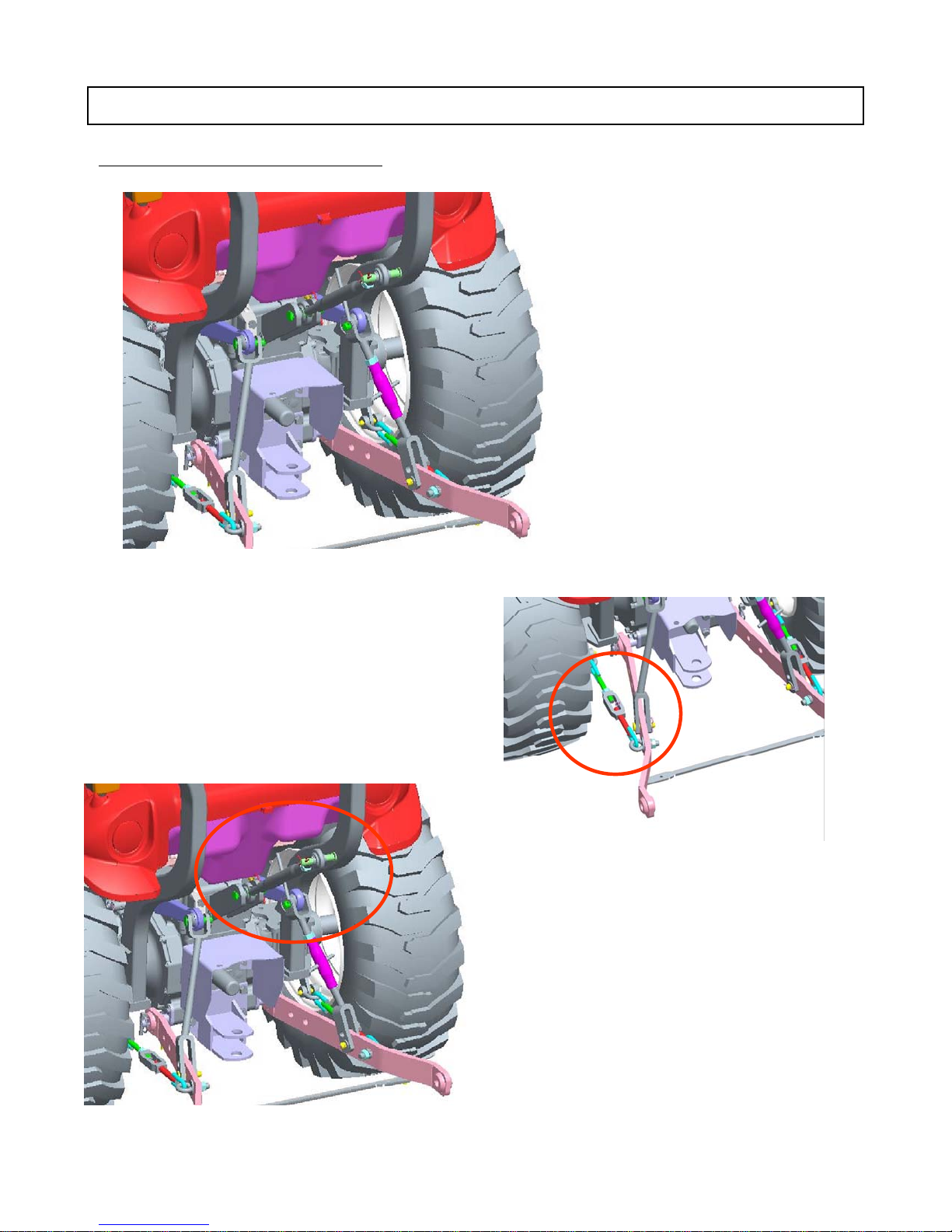
THREE-POINT HITCH AND DRAWBAR
▶
ADJUSTMENT OF THE TOP LINK
OPERATING 3-POINT LINKAGE
▶ADJUSTING THE CHECK CHAIN
To adjust the check chain, turn the turnbuckle to
lengthen or shorten the chain and tighten the lock
nut when the correct adjustment is achieved.
Lengthening or shortening the top link will
change the angle of the implement.
57
Page 59
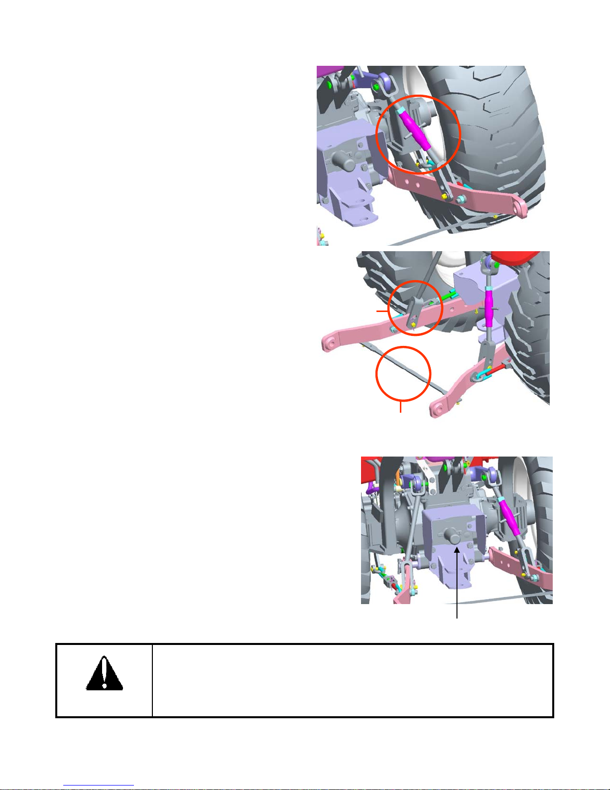
■ Adjustment of the Lower Link
■
Mounting Implement
A
The adjustment is done with the adjusting handle on
the right hand yoke rod.
To shorten or lengthen the yoke rod turn the
adjusting handle.
When adjusted correctly tighten the lock nut
securely.
■ Adjustment of the Yoke Rod on the Lower Link
For different applications change the position of the
yoke rod on the lower link holes as shown and insert
the pin in the direction of the arrow
■ Use of the Retention Rubber
When not using implements on the three point
linkage use the rubber as shown to prevent tire
damage.
YOKE ROD
If the PTO is used, remove the safety cover off the PTO
shaft.
Adjust the yoke rod on the lower links to suit the implement
in use.
ttach the left lower link, then attach the right lower link
using the adjusting handle on the leveling box if required.
Attach the top link.
Attach the PTO shaft to the tractor if used, making sure that
it is locked in place.
Adjust the check chains to suit the implement and tighten
the locknuts.
To remove an implement reverses the procedure.
Do not attach a PTO shaft with the engine running and ensure all safety shields
are in place.
RETENTION RUBBER
PTO safety cover
CAUTION
58
Page 60
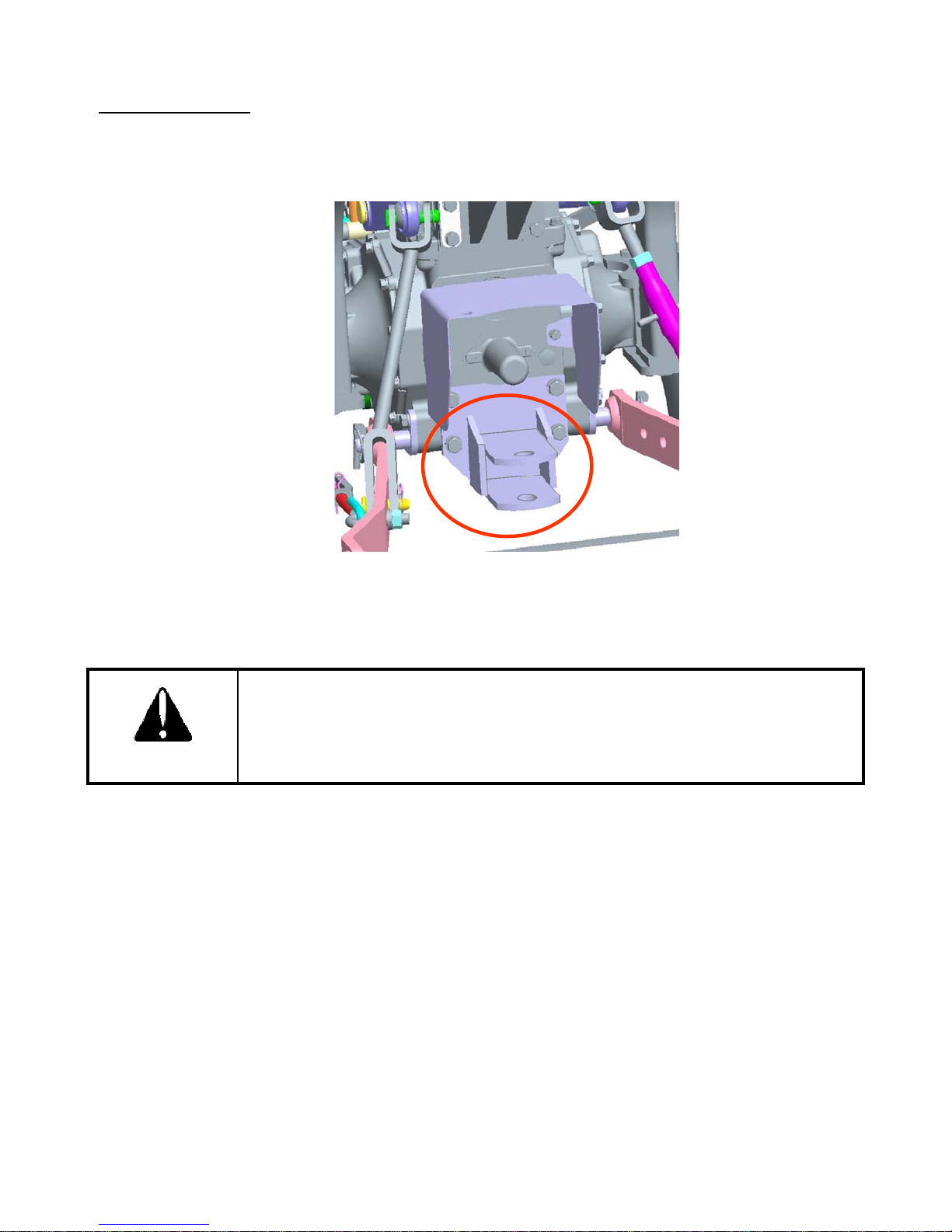
TRAILER HITCH
The trailer hitch is used for towing implement. Do not exceed maximum vertical load on drawbar.
Maximum Vertical Load : Approximate. 400kg(880lbs)
DANGER
TRAILER HITCH
Only use trailer hitch to tow and keep the 3 point linkage in raised position
when towing with the drawbar.
Position can create unbalance causing the Tractor to roll-over & Result the
death or serious injury.
59
Page 61

SECTION 4
FUEL
68
SERVICING
MISCELLANEOUS
76
ADJUSTING
TOE
IN
‥‥‥‥‥‥‥‥‥‥‥‥‥‥‥‥‥‥‥‥‥‥‥‥‥‥‥‥‥
78
MAINTENANCE AND SERVICE
MAINTENANCE AND ADJUSTMENT ‥‥‥‥‥‥‥‥‥‥‥‥‥‥‥‥‥‥‥‥‥‥
6 1
PERIODICAL CHECK AND SERVICE TABLE ‥‥‥‥‥‥‥‥‥‥‥‥‥‥‥‥‥‥ 61
LUBRICATION CHART ‥‥‥‥‥‥‥‥‥‥‥‥‥‥‥‥‥‥‥‥‥‥‥‥‥‥‥ 62
SERVICING ENGINE ‥‥‥‥‥‥‥‥‥‥‥‥‥‥‥‥‥‥‥‥‥‥‥‥‥‥‥‥‥ 63
OPENING METHOD OF EACH COVER ‥‥‥‥‥‥‥‥‥‥‥‥‥‥‥‥‥‥‥‥‥63
ENGINE OIL ‥‥‥‥‥‥‥‥‥‥‥‥‥‥‥‥‥‥‥‥‥‥‥‥‥‥‥‥‥‥‥‥ 64
AIR CLEANER ‥‥‥‥‥‥‥‥‥‥‥‥‥‥‥‥‥‥‥‥‥‥‥‥‥‥‥‥‥‥‥ 65
ENGINE COOLANT ‥‥‥‥‥‥‥‥‥‥‥‥‥‥‥‥‥‥‥‥‥‥‥‥‥‥‥‥‥ 66
‥‥‥‥‥‥‥‥‥‥‥‥‥‥‥‥‥‥‥‥‥‥‥‥‥‥‥‥‥‥‥‥‥‥‥
FAN BELT ‥‥‥‥‥‥‥‥‥‥‥‥‥‥‥‥‥‥‥‥‥‥‥‥‥‥‥‥‥‥‥‥‥ 69
CHECKING HOSES AND CLAMPS ‥‥‥‥‥‥‥‥‥‥‥‥‥‥‥‥‥‥‥‥‥‥ 69
SERVICING TRANSMISSION ‥‥‥‥‥‥‥‥‥‥‥‥‥‥‥‥‥‥‥‥‥‥‥‥‥ 71
TRANSMISSION OIL ‥‥‥‥‥‥‥‥‥‥‥‥‥‥‥‥‥‥‥‥‥‥‥‥‥‥‥‥ 71
FRONT AXLE OIL‥‥‥‥‥‥‥‥‥‥‥‥‥‥‥‥‥‥‥‥‥‥‥‥‥‥‥‥‥‥ 73
SERVICING ELECTRICAL ‥‥‥‥‥‥‥‥‥‥‥‥‥‥‥‥‥‥‥‥‥‥‥‥‥‥ 74
BATTERY ‥‥‥‥‥‥‥‥‥‥‥‥‥‥‥‥‥‥‥‥‥‥‥‥‥‥‥‥‥‥‥‥‥ 74
CHECKING THE WIRING HARNESS AND FUSES ‥‥‥‥‥‥‥‥‥‥‥‥‥‥‥‥ 75
‥‥‥‥‥‥‥‥‥‥‥‥‥‥‥‥‥‥‥‥‥‥‥‥
GREASING THE TRACTOR ‥‥‥‥‥‥‥‥‥‥‥‥‥‥‥‥‥‥‥‥‥‥‥‥‥ 76
GAP ADJUSTMENT ON THE FRONT AXLE ‥‥‥‥‥‥‥‥‥‥‥‥‥‥‥‥‥‥‥ 77
ADJUSTING THE BRAKES ‥‥‥‥‥‥‥‥‥‥‥‥‥‥‥‥‥‥‥‥‥‥‥‥‥‥ 77
ADJUSTING THE THROTTLE LEVER ‥‥‥‥‥‥‥‥‥‥‥‥‥‥‥‥‥‥‥‥‥ 78
-
TIRE PRESSURE ‥‥‥‥‥‥‥‥‥‥‥‥‥‥‥‥‥‥‥‥‥‥‥‥‥‥‥‥‥‥ 78
STORAGE ‥‥‥‥‥‥‥‥‥‥‥‥‥‥‥‥‥‥‥‥‥‥‥‥‥‥‥‥‥‥‥‥‥ 79
SERVICE PRIOR TO DAILY AND SHORT TERM STORAGE ‥‥‥‥‥‥‥‥‥‥‥‥ 79
FOR DAILY OR SHORT STORAGE ‥‥‥‥‥‥‥‥‥‥‥‥‥‥‥‥‥‥‥‥‥‥ 79
LONG TERM STORAGE ‥‥‥‥‥‥‥‥‥‥‥‥‥‥‥‥‥‥‥‥‥‥‥‥‥‥‥ 79
REUSE AFTER LONG TERM STORAGE ‥‥‥‥‥‥‥‥‥‥‥‥‥‥‥‥‥‥‥‥ 80
TROUBLESHOOTING ‥‥‥‥‥‥‥‥‥‥‥‥‥‥‥‥‥‥‥‥‥‥‥‥‥‥‥‥ 81
60
Page 62

MAINTENANCE AND ADJUSTMENT
m
D
D
5
g
Air cleaner
△△△△△
●
○
q
g
○
q
o
il
p
o
p
PERIODICAL CHECK AND SERVICE TABLE
○ Check, Top-up or adjust ● Replace
△ Clean or wash ★ Consult the service Dealer
Divi
sion
Engine oil
Oil filter
Radiator
coolant
Radiator
En
Radiator fins &
ine
screen
Fuel
Fuel filter
Fan belt
Battery
Ite
Service interval(hour meter,mark)
aily
○●●●●●●
○
○
○
○
11223344556
005000500050005000500
0
●●●
△△△
○△○△●○○△○△●
○○○○○○
0
Comment
To correct level on the
dipstick
Check daily top up if
required
Check daily for
damages leakage
Clean if re
Fill tank
Check daily
Check daily
uired
Loose nuts and
bolts
Radiator hose
clamp
Transmission
o
Strainer
Transmissi
HST oil filter
Frontaxle oil
Brake
n
Operation of
each lever
edal
○
○
○● ●
△△
●●
●○○○○○○
○
○
Check daily ,Tighten
Tighten if required
Change every 300
hours after first 50
hours
61
Page 63
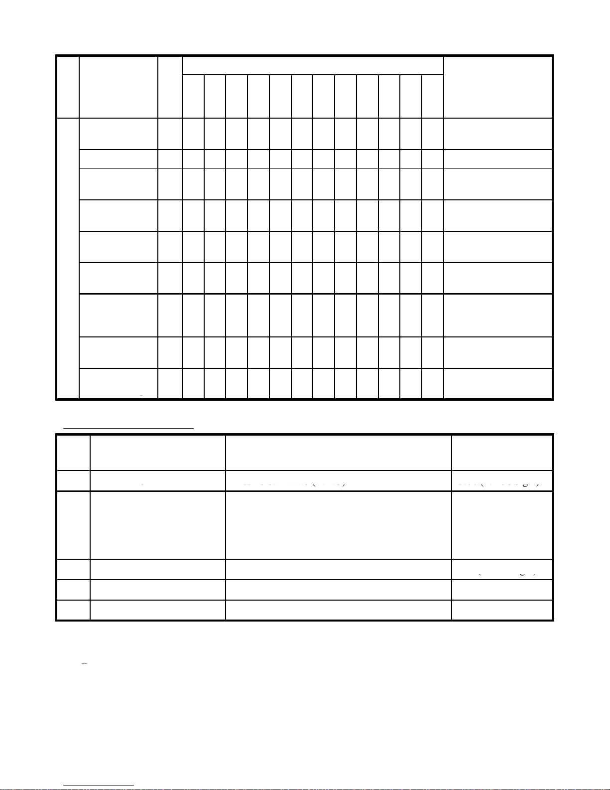
Division
F
g
g
○
Adjust every 300 hours
Replenish every 50
g
g
1
RADIATOR
Fresh clean Water(L.L.C)
5.6ℓ (1. 48US gal)
(
)
(g)
①
Item
Daily
Service interval(hour meter,mark)
1
1
2
2
3
3
4
4
5
5
5
0
5
0
5
0
5
0
5
0
0
0
0
0
0
0
0
0
0
0
6
5
0
0
0
Comment
ree play of
steering wheel
Toe-in
Grease in front
wheel hub
steerin
joint
Chassis
Wheel nut
fastening torque
Operation of
the instrument
Grease each
nipple
Loose bolts and
nuts
Check the
electric wirin
wheel
○
★★
○
○
○○○○○○○○○○○○
○
○○○
Check every 300 hours
Grease every 900 hours
Check daily
Check daily
hours (everyday in
dusty conditions)
Check daily
LUBRICATION CHART
No. Filling point Fillings
API : CD/CE grades
2 ENGINE
Above:25°C(77°F)…SAE30 or 10W-30
0°C to 25°C(32°F to 77°F)…SAE20 or 10W30
Below 0°C(32°F)…SAE 10W or 10W30
3 TRANSMISSION CASE See below* 17ℓ
4 FRONT AXLE Gear oil #80 or #90 4.5ℓ (1.19 US gal)
5 FUEL TANK Diesel fuel 25ℓ (6.6 US gal)
Quantity Liter
(US gal.)
4.3ℓ (1.14 gal)
5.81 US gal
* Recommended Transmission oil
RPM Tractor Hydraulic Fluid or Textron TDH Premium (CALTEX)
② TDH Oil or TDH Oil special (TEXACO)
③ Chevron 1000THF (CHEVRON)
62
Page 64
SERVICING ENGINE
■
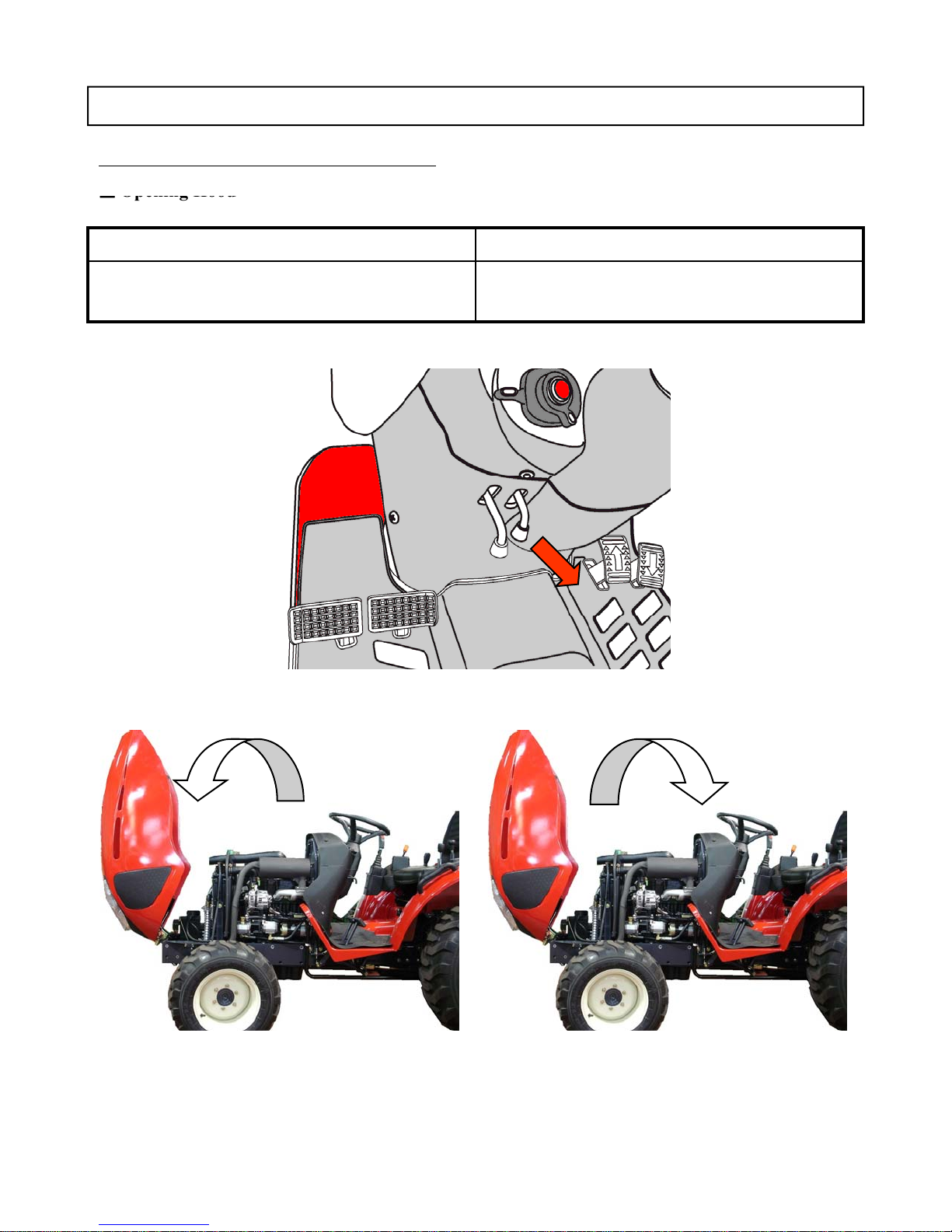
Opening Hood
OPENING METHOD OF EACH COVER
Opening Lowering
1.Pull in the hood lock pin to unlock. 1. Lift the hood slightly to release the latch.
2. Lower the hood until locked.
Opening
Lowering
63
Page 65
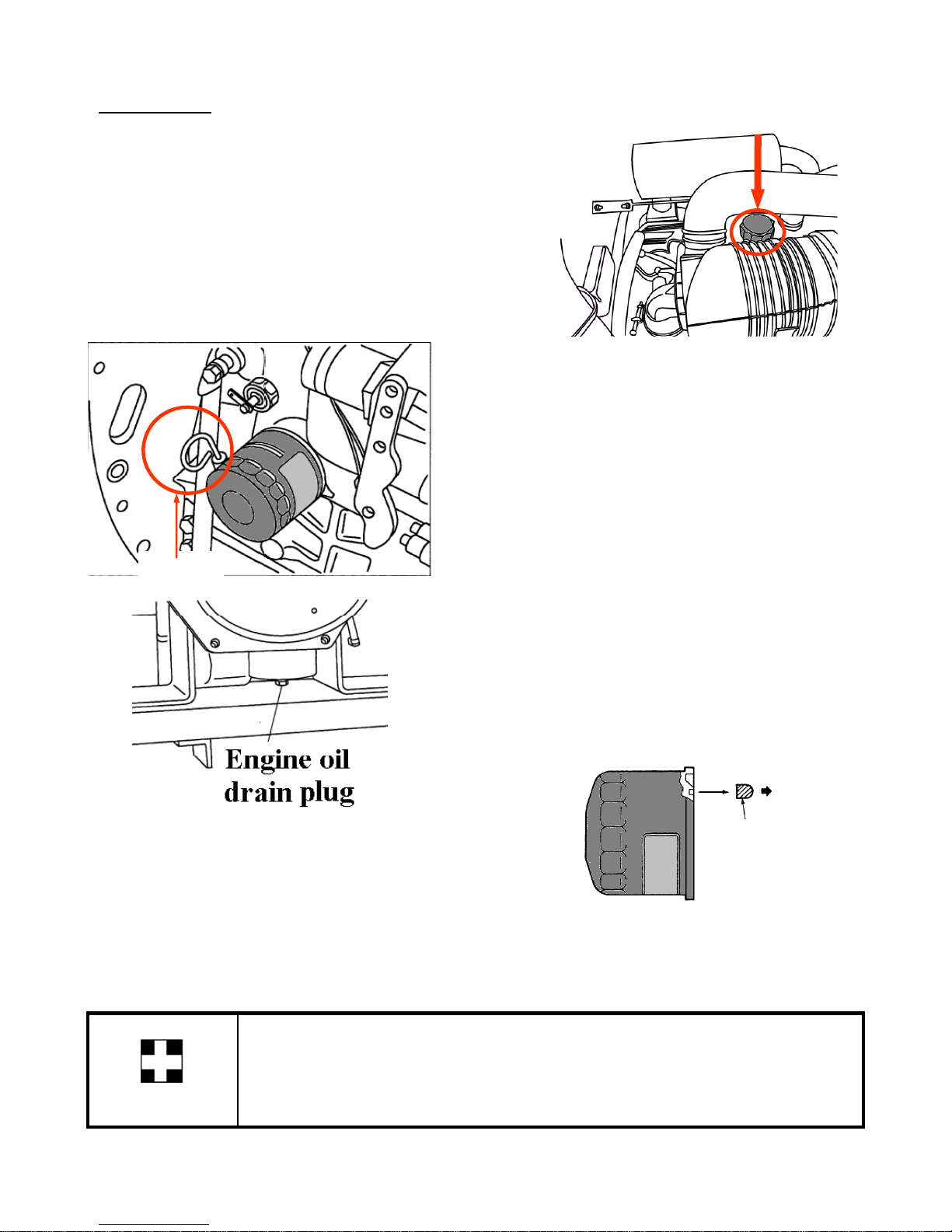
ENGINE OIL
2. Check the engine oil when engine is cool enough
Shi
10W/30
2.Smear lightly the rubber seal on the new filter with oil
When changing the oil always change the filter
■ Checking Engine Oil
1. Park tractor on level surface
3. Pull out the dipstick, wipe it clean and dip in the oil sump.
4. Ensure that oil level is near the upper mark between the
upper and lower mark.
5. If too low, add oil through the oil filler cap, but never
excess 100 hours of service interval.
■ Changing Engine Oil
1. Park tractor on level surface, shut-off engine
2. Open the hood.
3. Remove the drain plug from the bottom of the
oil pan and allow the oil to drain.
4. Replace and install the sump plug.
5. Fill the engine oil to the correct level on the
dipstick (approximately 1.14 US gal).
dipstick
6. The grade of oil to be used will depend on the
ambient temperature.
pped from factory :
Temperature over 77Ԭ : SAE 30
32Ԭ-77Ԭ : SAE20 or 10W/30
below 32Ԭ : SAE 10W
Engine Oil Cap
■ Changing Engine Oil Filter
1. Remove the oil filter using a filter wrench.
to ensure.
3.Turn the filter clockwise until the seal contacts the
base and then turn it another 2/3 turn to tighten it
Always use the same oil, as using different oils or specifications can cause
damage.
IMPORTANT
Dispose off the old oil as per local regulations.
Apply oil
Installing New Oil Filter
.
64
Page 66
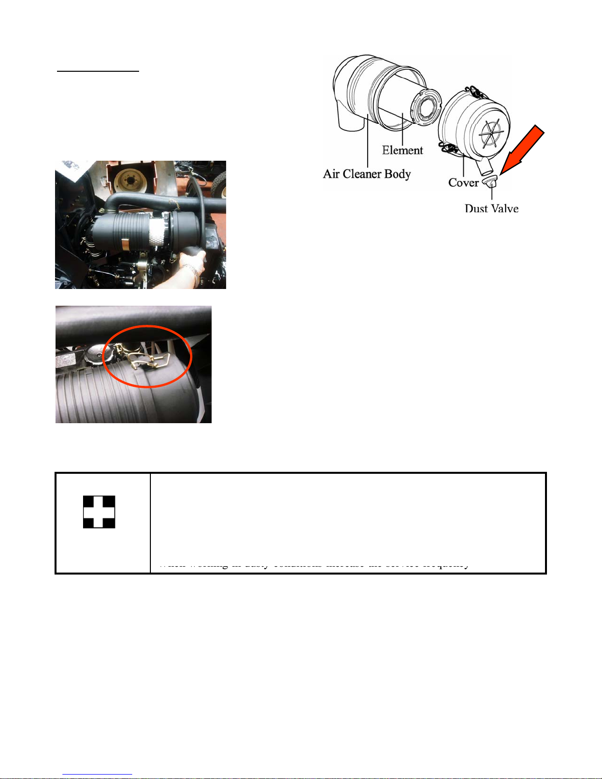
AIR CLEANER
between thumb and fingers to let excess dust out and
■
Cl
t
When working in dusty conditions increase the service frequency
■ Squeezing Dust
To remove the dust from the evacuator valve squeeze it
wipe around the valve to keep it clean from outside.
1. Open the hood
2. Remove the element by unlocking the clamp.
eaning the Elemen
3. Remove dust by blowing it out of the
element with compressed air.
4. Check the element to ensure it is not damaged.
5. Reassemble the element.
▶ Replace the element after cleaning it 5 times or it is damaged.
Never beat the element on a stone or concrete floor/wall to clean it Check all
connections and hoses especially on the clean side of the air cleaner to ensure
no dusty air can enter the engine.
Check the element for flaws by putting a light inside the element.
IMPORTANT
When reassembling make sure all surfaces seal correctly to keep dust out.
65
Page 67
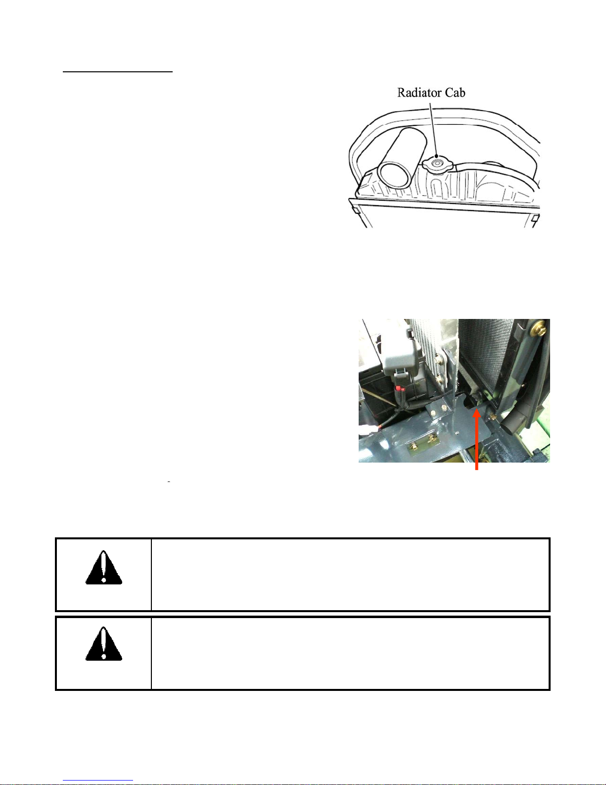
ENGINE COOLANT
2. Shutoff engine. Allow engine to cool enough
6. To give a thorough clean run a hose into the radiator and
p
Drain Cock
All
■ Checking Coolant
1. Park tractor on level surface
2. Check the coolant when engine is cool enough.
3. Open the hood.
4. Remove the radiator cap.
5. Ensure that the coolant is up to the filler neck and that it
is clean with the correct anti-freeze or anti corrosion
inhibitor in it.
6. If low, add coolant.
■ Changing the Coolant
1. Park tractor on level surface
.
3. Open the hood.
4. Open the drain cock in front of the Radiator to drain the
coolant.
5. Open the radiator cap at the same time.
flush it out.
7. Close the cock
8. Fill the radiator with a coolant mixture of water and
corrosion inhibitor or anti freeze.
9. Close the radiator cap.
10. Start the engine and allow it to run for approx 5minutes.
Check the water level again and top up if required.
Do not remove the radiator cap on a hot engine.
Allow the engine to cool down and then turn the cap slowly to ensure, that there
is no excessive pressure in the radiator.
CAUTION
Serious burns, can result from the contents of pressurized, hot radiators.
ow the engine to cool down completely before opening radiator cap.
DANGER
66
Page 68
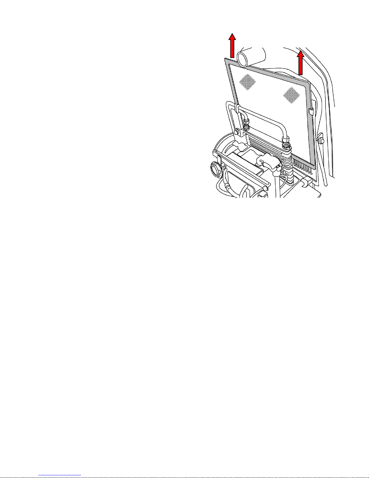
■ Cleaning the Radiator and Cover
low pressure compressed air or clean water
Insects, grass straw and dust can all block the radiator
and reduce its efficiency.
1. Park tractor on level surface, shut-off engine
2. Open the hood.
3. Remove the radiator cover (pull upward) and clean it.
4. Clean the radiator between the fins and tube by using
.
■ Anti Freeze
Frozen cooling water can damage the engine.
Before replacing the anti freeze solution flush the radiator.
Mix the anti freeze solution in accordance with the instructions applicable to the brand of anti freeze
and the locals climate.
Replace the solution in the radiator.
In case of loss of solution due to evaporation or overflow, replace with the original mixture ratio.
67
Page 69
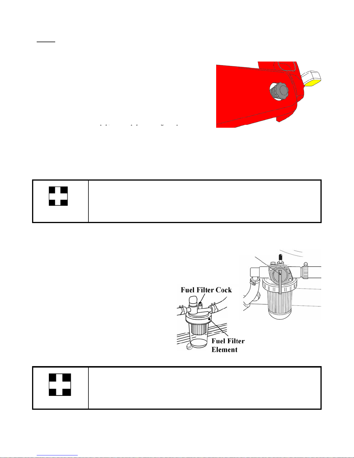
FUEL
g
pty,
py, py g p
i
fil
Use clean diesel fuel only.
■ Checking and Refuelin
1. Turn key switch ON.
2. Check the fuel level with the fuel gauge on instrument
panel.
If fuel is near to em
the empty warning lamp turns
on.
3. Fill the fuel tank, if too low.
4. It is a good practice to refill the tank immediately after
use to avoid condensation
As diesel fuel equipment is susceptible to contamination by dust or water,
Ensure that all dust and water is kept well away from the fuel tank.
IMPORTANT
■ Cleaning the Fuel Filter
This is the primary filter and removes water and coarse dirt
from the fuel.
1. Close the fuel cock.
2. Remove the filter
①
Fuel Filter Cock
3. Wash it or replace the filter element.
4. Bleed the air from the filter
Never use petrol (gasoline) thinner or similar inflammable material to wash the
mary fuel
pr
After replacing the filter always bleed the system.
IMPORTANT
②
ter.
68
Page 70
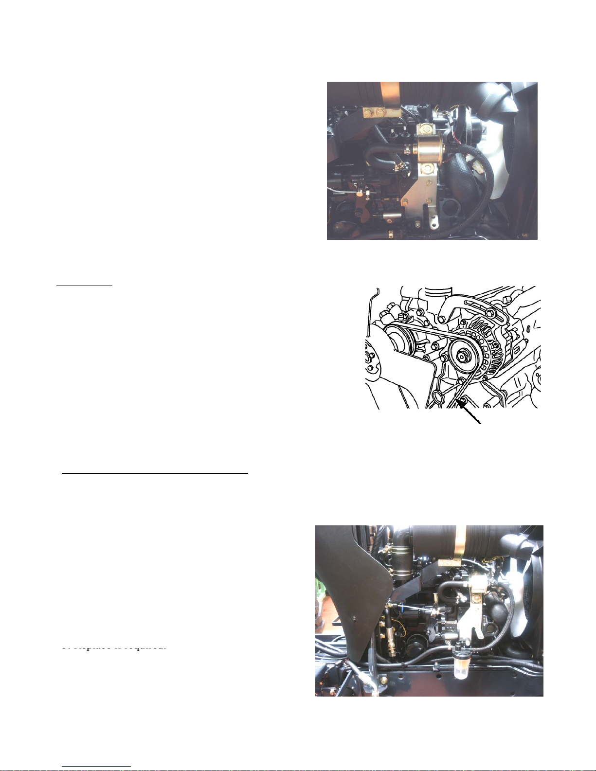
■ Bleeding the Fuel System
Check the f
To adjust the fan belt loosen the top bolt on the alternator, Move
1. Park tractor on level surface
5. Replace if required.
The fuel system is to be bled whenever the tractor
has run out of fuel or when filters, pipes or other
components have been replaced.
1. Fill the tank with fuel.
2. Open Fuel filter cock.
3. Turn the key “ON” position for a while.
4. Start the engine and allow it to run for a while.
5. Stop the engine.
6. The bleeding of the system is now finished
FAN BELT
an belt tension regularly and adjust if required.
The correct tension is if the center of the belt is pushed.
With a finger it moves in approx. 10 to 12 mm
(0.4 to 0.5 in) under 10Kgf(22 lbf)[98N] as shown in the picture.
the alternator to the desired position and tighten the bolt.
Also ensure that the bolts at the bottom of the alternator are tight.
10 to 12 mm (0.4 to 0.5 in) under
10Kgf(22 lbf)[98N]
CHECKING HOSES AND CLAMPS
The fuel lines, radiator hoses, hydraulic and rubber hoses are consumables, which deteriorate by age
and use. Check them regularly and replace if faulty.
■ Checking the Fuel Hoses
2. Shutoff engine. Allow engine to cool enough.
3. Open the hood.
4. Check the fuel hoses for damage and leakage
6. Tighten Clamps
69
Page 71
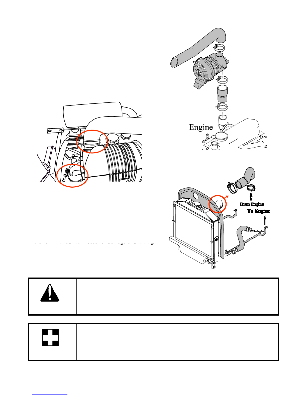
■ The Air Intake Hoses and Clamps
■
The Radiator Hoses and Clamps
4. Check the radiator hoses for damage and leakage.
Damaged fuel lines leak and cause fires
1. Park tractor on level surface
2. Shutoff engine. Allow engine to cool enough.
3. Open the hood.
4. Check the air intake hoses for damage.
5. Tighten Clamps
1. Park tractor on level surface
2. Shutoff engine. Allow engine to cool enough.
3. Open the hood.
5. Replace if required.
6. Tighten Clamps
Damaged radiator hoses can cause hot water burns and in severe cases seize the
engine.
CAUTION
Incorrect wiring or fuses can cause fires to both the tractor and surrounding
area so get the dealer to check it annually.
Likewise fuel pipes and wiring age with use.
.
IMPORTANT
Ask your dealer to check it at least once every 2 years and replace as required.
70
Page 72
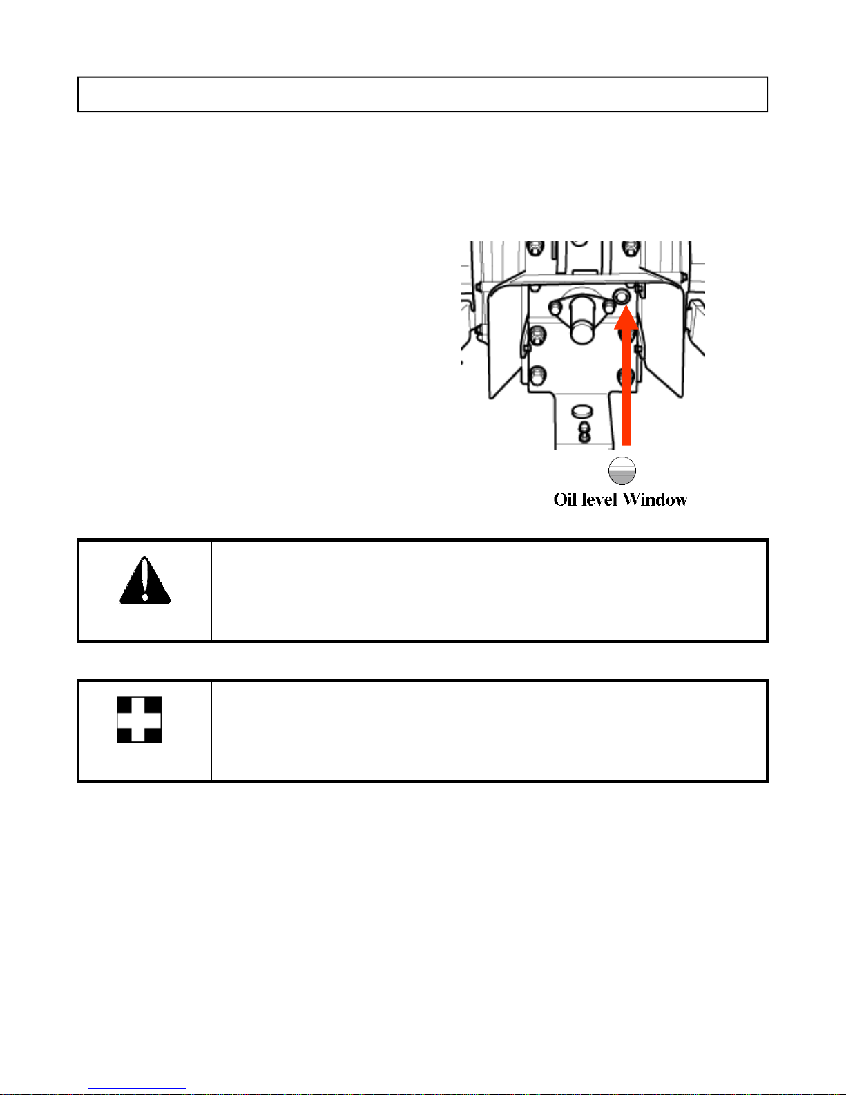
SERVICING TRANSMISSION
The t
■
Checking Transmission Oil
TRANSMISSION OIL
ransmission oil is used to lubricate and used as hydraulic fluid. It is important to use the proper
oil. Using the recommendation oil is preferred for better performance. Consult authorized
dealer/distributor for details.
Transmission Oil Capacity : 17ℓ(4.5 US gals)
1. Park tractor on level surface
2. Lower the implements to ground
3. Shutoff engine. Allow transmission oil to cool
enough.
4. Check the level with the sight window on rear
side of the transmission in rear of the seat. If
the level is low add oil through the filler hole.
CAUTION
IMPORTANT
Always ensure that you use the correct oil for topping up or oil changes.
Always use the same grade and specified oil as replacements.
Dispose off the old oil as per local regulations .
71
Page 73
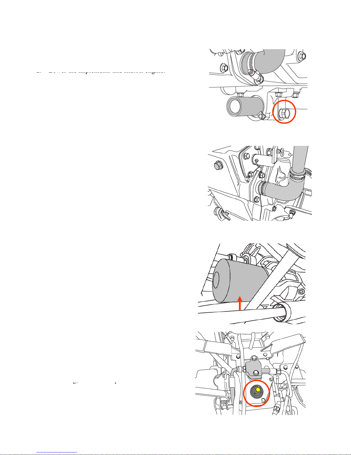
■ Changing Transmission Oil and Filter and Cleaning Strainer
2.
Lower the implements and shutoff engine.
5.Loosen the hose clamp and detach the hose from the
Drain plug
transmission case
ith oil t
12. Remove the transmission oil cap at the top of
g,
g, p
1. Park tractor on level surface
3. Remove the drain plug at the bottom of the
transmission case (and drain plug at the side of mid
PTO case, if mid PTO kit is assembled).
4. Drain the oil completely into container.
strainer.
6. Remove the bolt and remove the strainer.
7. Clean the strainer
8. Reinstall the strainer, bolt and hose
Drain plug of MID PTO
9. Remove the HST filter at the front of the HST
unit with filter wrench.
10. Smear lightly the rubber seal on the new filter
w
o ensure.
11.Tighten the filter until the seal contacts the
base and then turn it another 2/3 turn to
tighten it.
hydraulic cylinder case.
13. Fill the transmission oil to the correct level on
the sight window.
14. After fillin
install the cap.
15. Run engine for a few minutes and stop it.
of
HST filter
16. Check the oil level. Add if required.
72
Page 74
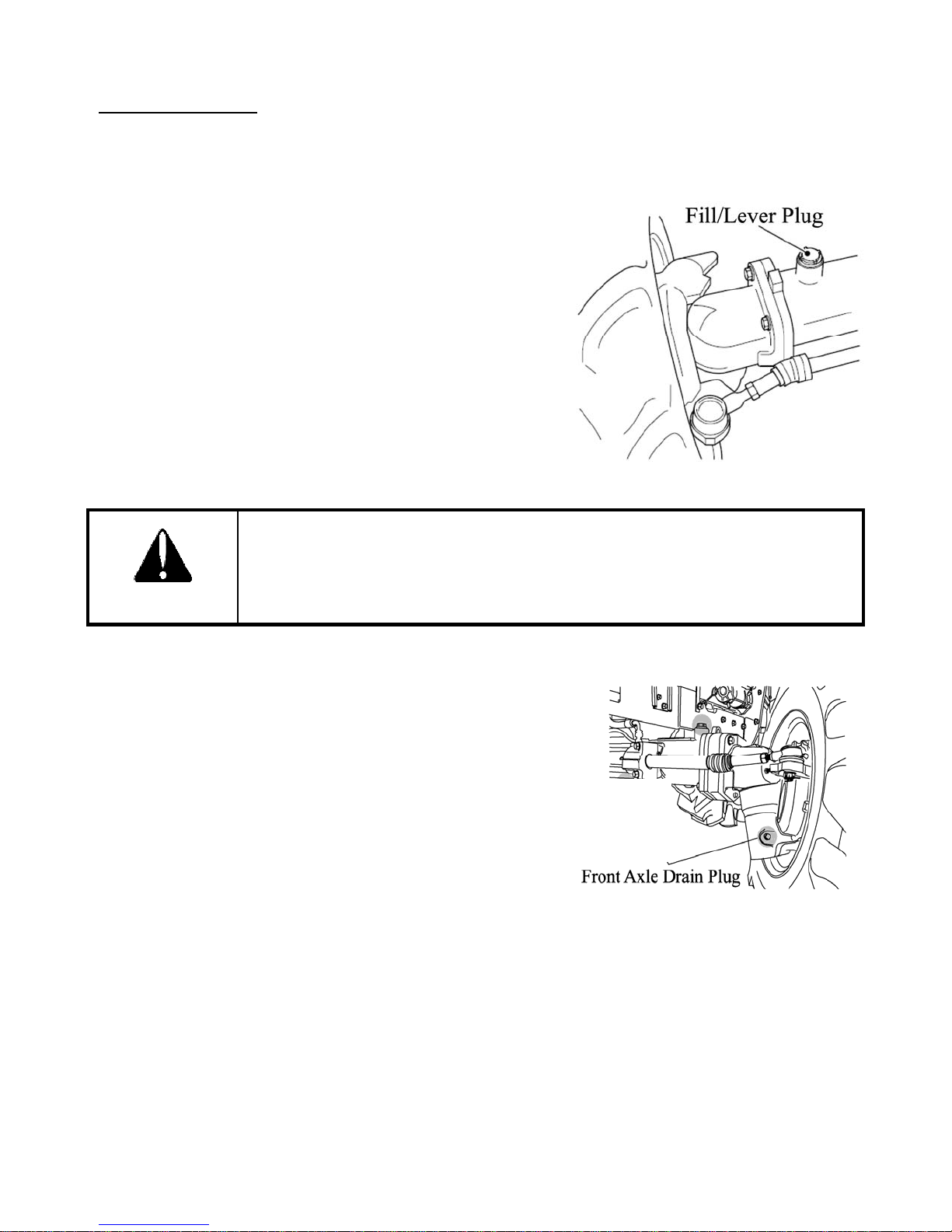
FRONT AXLE OIL
6
Use SAE 80 or SAE 90 gear oil for the front axle oil. Do not mix different grades.
Front Axle Oil Capacity : 4.5ℓ (1.14 US gal)
■ Checking Front Axle Oil
1. Park tractor on level surface
2. Lower the implements and shutoff engine.
3. Remove the oil cap.
4. Wipe the dipstick on oil cap. Dip and screw the oil cap
into the front axle.
5. Unscrew oil cap and pull out.
6. Check the level with the dipstick. If the level is low add
oil through the filler hole.
Always ensure that you use the correct oil for topping up or oil changes.
CAUTION
■ Changing Front Axle Oil
1. Park tractor on level surface
2. Lower the implements and shutoff engine.
3. Remove the front axle oil cap.
4. Remove the drain plug at the bottom of the front axle
case and the drain plugs at the front of the both spindles.
5. Drain the oil completely into container.
. Install the drain plugs correctly
7. Fill with new oil to the correct level in the filler hole.
8. Reinstall the oil cap.
73
Page 75
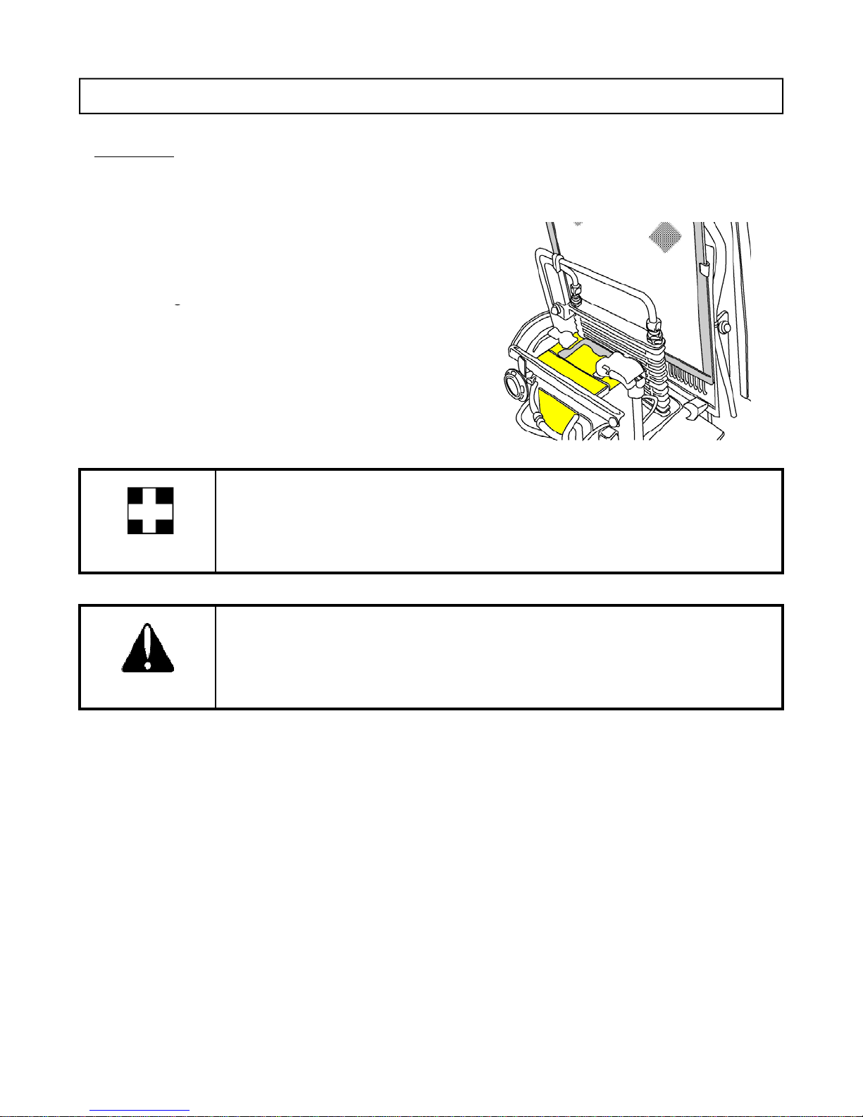
SERVICING ELECTRICAL
The original battery is maintenance free. But the water in the electrolyte can evaporate during use
g
g
IMPORTANT
BATTERY
So it needs to service for longer life.
■ CHECKING THE BATTERY
The electrolyte level of the battery can evaporate during use
thus lowerin
Where it does so replace it with distilled water.
Where a spillage has reduced the level, replace it with
electrolyte.
the level.
.
Low electrolyte levels can cause premature battery failure and corrosion.
Electrolyte contains acid and can cause serious burns.
Any spillage on skin should be washed off by running water immediately.
CAUTION
■ Battery Maintenance
Low temperatures will affect the performance of batteries so take particular care of it in winter.
For long-term storage of the tractor, remove the battery and keep it in a cool dry room.
If it is on the tractor while stored, disconnect the negative terminal.
Batteries will self discharge if left for a period of without use time.
To keep them in good condition charge them once a month in summer and every second month in
winter.
When replacing the original battery, ensure that the replacement battery is the same size.
Failure to do so can cause problems with the electrical circuit.
74
Page 76
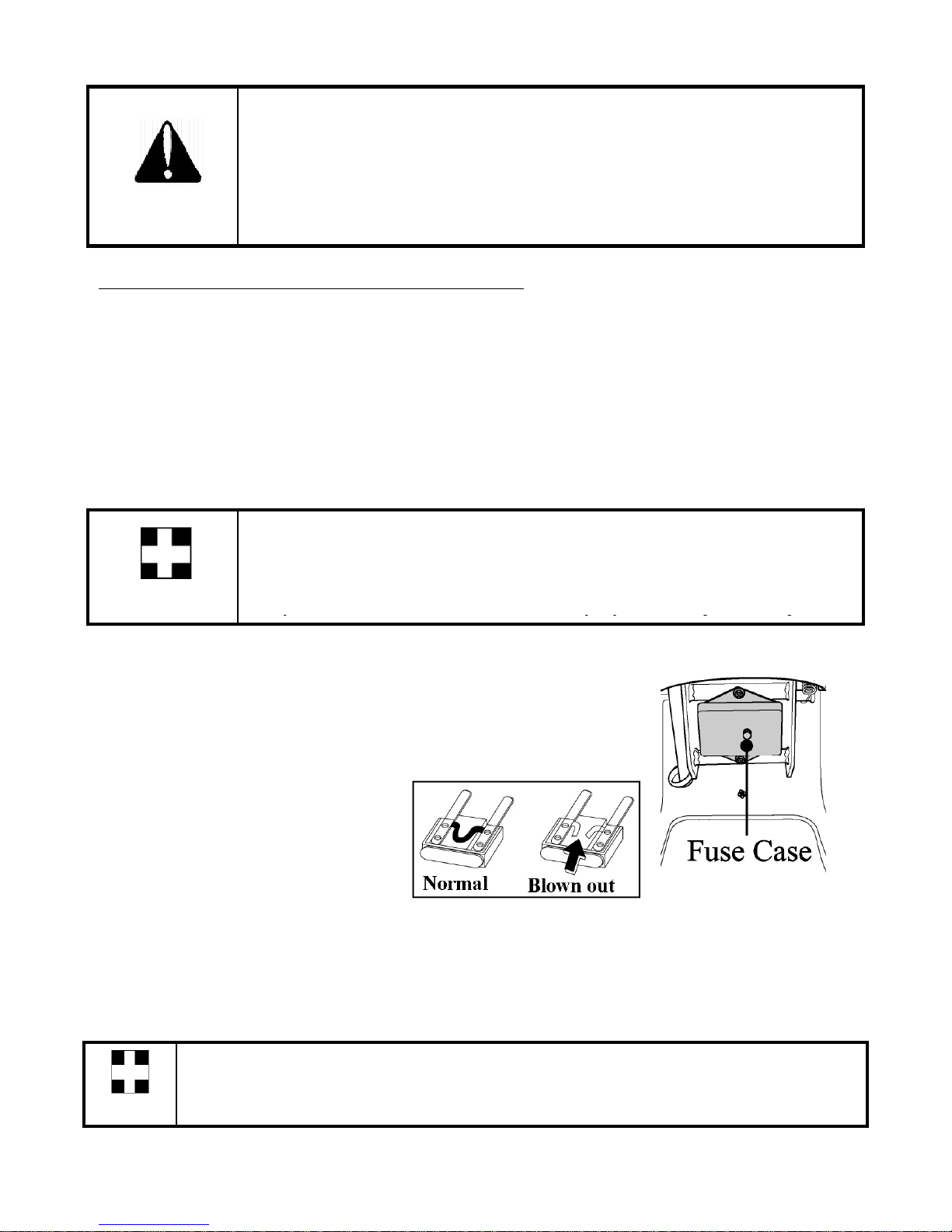
Always disconnect the negative terminal first when removing the battery and
wiring or reduce efficiency of components
yyypq
Using a large capacity fuse or wire burn out the wiring system
always connect the positive terminal first when fitting the battery.
When connecting the battery leads make sure not to reverse the polarity.
Quick charging will reduce battery life.
CAUTION Disconnect the terminals prior to charging the battery to avoid damage to the
circuit and electrical instruments.
CHECKING THE WIRING HARNESS AND FUSES
Loose wires make inferior connections and damaged wires can cause short circuits, fires burnt
.
Replace or repair any faulty wiring or insulation.
If a fuse burns out again after it has been replaced, do not replace it with wire or a high
capacity fuse, find the cause and rectify it or get an auto electrician to do so.
Where insulation is chafed or peeled off, recover the area with a good quality insulation tape. Where
wiring comes out of it’s fitting replace it correctly with the standard fitting.
Incorrect wiring or fuses can cause fires to both the tractor and surrounding area
so get the dealer to check it annually.
Likewise fuel pipes and wiring age with use.
IMPORTANT
Ask your dealer to check it at least once every 2 years and replace as required.
■ REPLACING FUSES
The circuit has 8 blade type fuses in its wiring circuit
When a fuse has blown replace it with one of the same value.
.
Use fuse tongs to replace fuses
■ MAIN FUSES
The wiring harness is equipped with 3 main fuses who’s function is to preserve the wiring.
However when a main fuse blows the entire circuit is dead.
Always check the reason & rectify before replacing the fuse of the same value.
To indicate that the fuse is blown it will be discolored.
Always check the reason for a blown fuse otherwise the new fuse is also likely to blow.
NEVER EVER USE WIRE in place of correct grade fuse.
important
75
Page 77
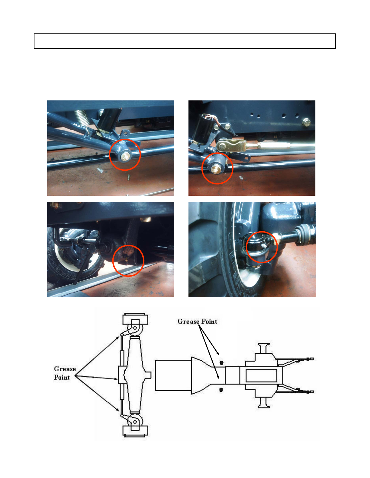
SERVICING MISCELLANEOUS
Grease the tractor according to the service schedule
GREASING THE TRACTOR
.
Ensure that grease nipples are cleaned well before any attempt is made to grease them
76
Page 78
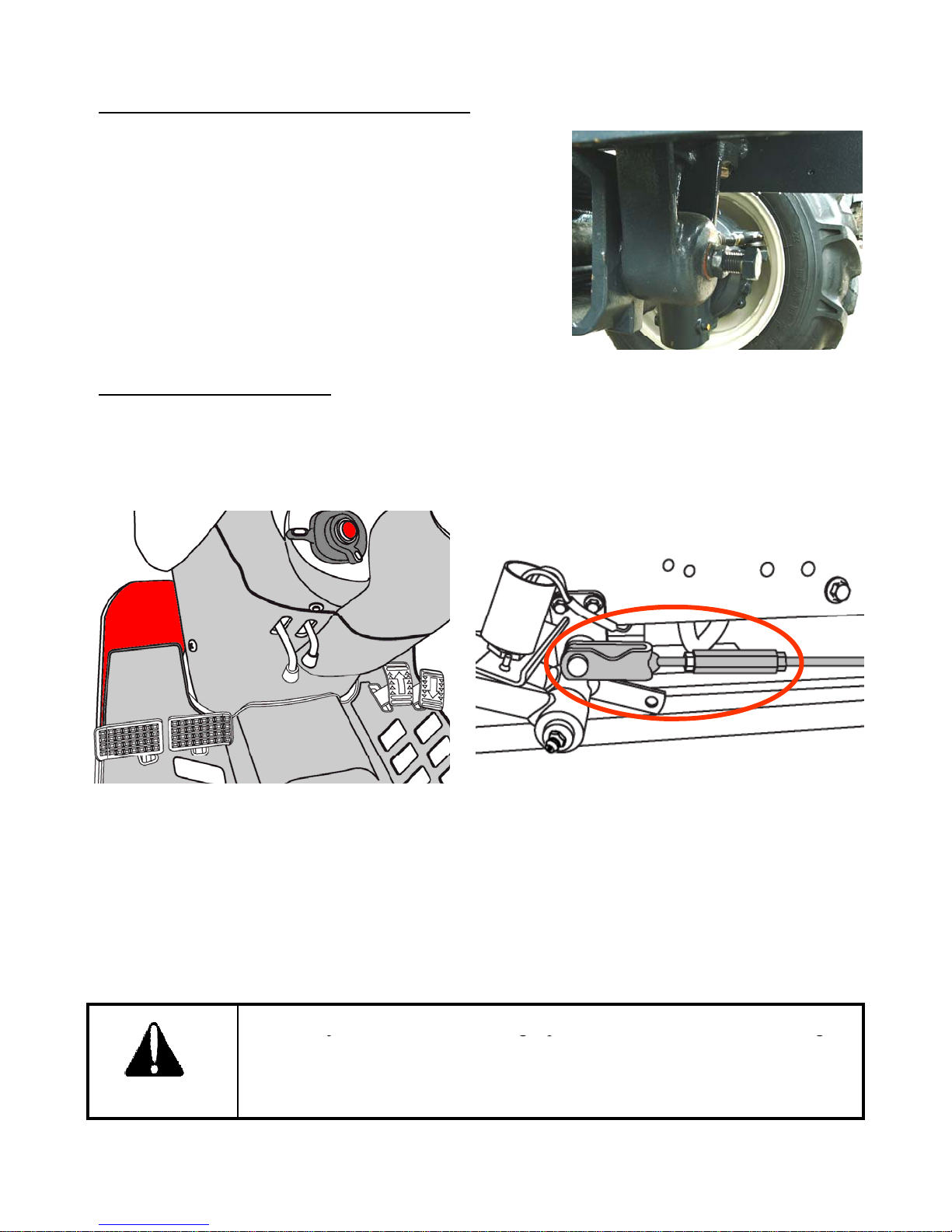
GAP ADJUSTMENT ON THE FRONT AXLE
Then loosen the nut and tighten the bolt fully and turn the
The correct pedal free play is 1.18~ 1.57 in
jgp g
Lift the front with a hydraulic jack to get the wheels of the
ground.
bolt ½ to loosen again in order to roll the center pivot metal
freely and tighten the nut again.
While the wheels arte still off the ground, move the axle on
the center pivot as a final check that the gap is set correctly
on the top of the pivot metal
ADJUSTING THE BRAKES
As is the case with the clutch, use of the brakes will change the pedal free play and the balance
between the right and left pedal.
■ Adjustment Method
Loosen the locknuts at each end and turn the rod to adjust the brake.
Turning it anticlockwise increases the free play, clockwise decreases it.
Tighten the locknuts.
Check that the free play is correct and the same on both pedals to ensure even braking
Uneven adjustment of the left and right pedal will result in one sided braking
when the pedals are connected and can cause serious accidents, especially at
high speeds.
CAUTION
Double check to ensure free play is the same on both pedals
77
Page 79
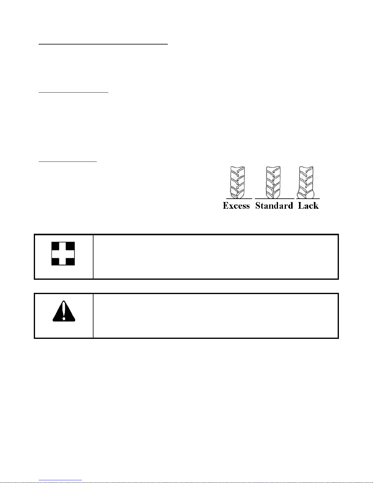
ADJUSTING THE THROTTLE LEVER
deal
If this lever is either loose or difficult to move please consult your dealer for rectification of the
problem.
ADJUSTING TOE-IN
If the toe-in adjustment is incorrect it can cause severe shaking of both the steering wheel and the
entire tractor.
The correct toe-in is 0.08~0.24in.(2~6mm) We recommend that the adjustment is made by the
er.
TIRE PRESSURE
The air pressure used in the tires has a direct bearing on
the life of the tire and its performance in the field.
Ensure that the tire pressures are correct and in
accordance with the table
To make a visual judgment see the drawing on the right.
IMPORTANT
DANGER
It is strongly recommended that tire pressures are checked with a proper gauge
only & visual inspections are relied upon.
Excess tire pressure can cause accidents!
78
Page 80

STORAGE
FOR DAILY OR SHORT TERM STORAGE
L
SERVICE PRIOR TO DAILY AND SHORT TERMS STORAGE
Wash the tractor and keep it clean.
Fill the tank to avoid condensation and rust.
Lower any attached implement to the ground before parking the tractor.
For long-term storage consult your dealer.
Clean the tractor and remove all dirt from field work.
Fill the fuel tank to avoid condensation and rust.
Lower the implement to the ground..
Keep it in a machinery shed or, if not available cover the unit if left outside.
In very cold conditions it is advisable to remove the battery and keep it inside in a warm
environment.
This will ensure effective starting when the tractor is required.
When the outside temperature is below 32Ԭ, replace the Antifreeze completely or drain the
coolant to protect the engine from damage from frozen coolant.
When washing the tractor ensure that the water does not get near electrical
components or the oil filter points.
To prevent short circuits remove the ignition key.
IMPORTANT
Do not wash the tractor when the engine is running.
LONG-TERM STORAGE.
When the tractor will not be used for a long time carry out the cleaning as for short term storage.
Drain the oil and replace with new oil.
Run the engine for approx. 5 min. to ensure that it has new oil throughout the engine.
Drain the coolant from the radiator and remove the ignition key.
Attach a tag both the key and the steering wheel saying” No coolant”.
Lubricate all grease and oil points on the tractor.
Check the pressures and add a small amount of extra pressure.
ower any implement to the ground or store in a shady dry place.
Disconnect the clutch by using the clutch disconnecting arm.
Place a piece of wood under each tire to preserve the tire.
79
Page 81

After refilling the engine with the coolant run the engine for approx. 5-10 min.
IMPORTANT
Refit the battery and run the engine at idle for 30 min. to ensure optimum engine life.
at 1500-2000rpm every month as a corrosion prevention measure.
Either removes the battery or the negative terminal as mouse damage to wiring
can cause short circuits and fires.
Remove the ignition key and store in a safe place.
RE-USE AFTER LONG TERM STORAGE
Carry out a full check of all oils and coolant.
80
Page 82
TROUBLESHOOTING
r
The engine stops suddenly
Lack of fuel
Fill the tank and bleed the fuel
SYMPTOM CAUSE REMEDY
Engine
Turning the master brake,
switch will not operate the
starter
Master brake not pushed
in
Battery flat
Switch faulty
Push the clutch in
Charge or replace the battery
Dealer to repair or replace
Contact dealer for repair or
replace
Starter operates but not
enough to turn the engine
Low battery
Bad earth
Thick oil
Charge the battery
Clean the earth lead and tighten
Drain and replace with correct
oil
Starter operates OK but Air in fuel system Bleed the system
does not start the engine
Clogged fuel filter
No fuel being supplied
Glow plug disconnected or
Clean or replace both filters
Fill tank or turn tap on
Contact dealer for repair.
not working
Engine revolutions are Air in the fuel system Bleed the system
irregula
Faulty injector
Fuel pipe leak
Contact dealer for repair.
Contact dealer for repair
The engine stops at low
revolution
The engine revs. is too
high
Poor fuel injection
Faulty injection pump
Wrong valve clearance
Wrong idle setting
Faulty injector
Contact dealer for repair
Contact dealer for repair
Contact dealer for repair
Contact dealer for repair
Contact dealer for repair
Faulty governor Contact dealer for repair
system
Faulty injectors
Seized engine due to lack
Contact dealer for repair
Contact dealer for repair
of oil, the wrong oil or
lack of coolant
Sensitivity of safety
device is too high
Check safety device or Contact
dealer for repair
81
Page 83

SYMPTOM CAUSE REMEDY
Clogged air filter element
Clean or replace air filter
p
Contact dealer for repair
steering
Wor n components
Contact dealer for repair
Engine
The engine overheats Lack of coolant
Broken or misadjusted fan belt
Clogged radiator
Low oil
Reduced performance
of the engine
The injectors are clogged,
carbon coated and sticking
Low compression
Leaking valve seat
Incorrect valve gap
Faulty timing
Fuel shortage
Clogged air cleaner Clean the element
Oil warning light
comes on with the
engine running
Low oil level
Wrong oil
Faulty light or switch
Refill with coolant
Adjust or replace
Clean the core
Replace the oil to correct grade
Contact dealer for repair
Contact dealer for repair
Contact dealer for repair
Contact dealer for repair
Fill the tank and check fuel
quality
Low oil level
Wrong oil
Faulty light or switch
Brake
Steering Wheel
Clogged oil filter
Alternator light comes
on with the engine
running
Wiring fault
Faulty alternator
Low water level or faulty
battery
Broken or loose fan belt
Brake not working Incorrect free play
Worm or burnt lining
Left and right gap different
Brake pedal not
Faulty return spring Replace spring
returning
Steering wheel
shaking
Wrong toe in
Unequal tire pressure
Loose components
Excessive play in the
Worn steering shaft
Clogged oil filter
Contact dealer for repair
Contact dealer for repair
Top up or replace
Replace or adjust
Adjust to correct free play
Contact dealer for repair
Equalize
Adjust toe in
Inflate both to correct pressure
Tighten or replace if worn
Contact dealer for repair
82
Page 84

SYMPTOM CAUSE REMEDY
H
H
Air leaking in from a pipe
p
yp p
Contact deal
ir
When lifting relief
The stopper has slipped down
Adjust the stopper
Faulty alternator Faulty
m
m
g
g
p
Hydraulics are not
lifting
ydraulic system
Engine revs. too low
Lack of transmission oil
Increase engine revs.
Top up the oil to the correct
level
Repair or replace pipe or
replace
O ring on joint and tighten
Clean and change oil
Clogged suction filter
Contact dealer for repair
Faulty pum
er for repa
Faulty hydraulic valve
Contact dealer for repair
Faulty cylinder
Oil leak from pipe Loose pipe joint
Cracked pipe
Tighten joint
Replace or repair pipe
valve whistles
For any other hydraulic problems, please consult your dealer who has the correct equipment to
diagnose and repair the system.
Flat battery Faulty wiring
regulator
Broken or loose fan belt
Repair, reconnect or tighten as
needed. Contact dealer for
repair
Contact dealer for repair
Replace or adjust
Before anything else, check the electrolyte level of the battery and the connections. Top up
it required and clean and retighten the terminals
Electrical Syste
Dim headlights Low battery
Faulty wiring
Headlights not
working
Blown bulb
Blown fuse
Faulty contact
Charge or replace
Repair or replace as needed
Replace bulb
Replace fuse
Repair or replace and check
the earth
Horn not working Faulty horn button
Faulty wiring
Faulty horn
Indicator not workin
Blown bulb Replace bulb
Faulty flasher unit
Faulty wiring
Replace button
Repair or replace
Replace
Replace unit
Repair or replace
83
Page 85

SECTION 5
SPECIFICATIONS AND TIPS
SPECIFICATION ‥‥‥‥‥‥‥‥‥‥‥‥‥‥‥‥‥‥‥‥‥‥‥‥‥‥‥‥‥‥‥
8 5
SPECIFICATION TABLE ‥‥‥‥‥‥‥‥‥‥‥‥‥‥‥‥‥‥‥‥‥‥‥‥‥‥‥ 86
HARNESS DIAGRAM ‥‥‥‥‥‥‥‥‥‥‥‥‥‥‥‥‥‥‥‥‥‥‥‥‥‥‥‥ 88
FUEL SAVING TIPS ‥‥‥‥‥‥‥‥‥‥‥‥‥‥‥‥‥‥‥‥‥‥‥‥‥‥‥‥‥ 89
84
Page 86

SPECIFICATIONS
TYM
CO.,LTDpolicy
i
d
th
ight
t
The specifications on the following pages are given for your information and guidance. For
further information concerning your Tractor and equipment, consult your Authorized TYM
Dealer/Distributor.
soneofcontinuousimprovementan
er
ochangeprices,
specifications or equipment at any time without notice is reserved. All data given in this book
is subject to production variations. Dimensions and weights are approximate only and the
illustrations do not necessary show Tractors in standard condition. For exact information
about any particular Tractor, please consult your TYM Authorized Dealer/Distributor.
85
Page 87

SPECIFICATION TABLE
Firi
r
1-3-2
Coolant Capacity (Approximate)
5.6(1.5)
r
Diff
k
Mechanical( Foot brake)
Model T293 HST
Engine Maker Mitsubishi
Model S3L2
Type Vertical, Water Cooled 4-Cycle Diesel
Horse power , HP (㎾)
29 (21.3)
Rated Speed 2,800rpm
Number of cylinders 3
Displacement,cu in(cc) 80.4(1,318 cc)
Bore and stroke,mm(in) 78X92(3.07X3.62)
Compression ratio 22
ng Orde
Injection Pump Bosch M
Lubrication type Force feed (by trochoid pump)
Cooling system Forced cooling
,
liter(US gal)
Air Cleaner Dry Type with Dual element
Muffler Horizontal Round
Fuel Diesel
Fuel tank capacity 6.6 US gal(25L)
Electric Battery 12V45AH
Starting System Electrical with Cell Motor
Starter Capacity 12V,1.6Kw
Alternato
12V,50A
Drive train Transmission HST / 2 Range
Numbers of speed Infinite
MFWD(4 WD) Standard
erential Loc
Brakes Wet Disk
Steering Hydraulic Power
86
Page 88

MODEL T293 HST
k
S
d
2,000
586rpm
Steering
2.6 GPM(10LPM)
O
91.7 in(2,330mm)
Rear
9.5-20,4PR
(
)
()
Rear
14-17.5,10PR
PTO Type Independent
Control Electro-Hydraulic
Clutch Multiple wet Dis
Rear PTO Shaft SAE 1-3/8,6 spline
Speed 540rpm@Engine 2,602rpm
Mid PTO Shaft 10 Splines
pee
rpm@Engine 2,
Hydraulics Control system Open Center Open Center
Working pressure 1,813psi( 125bar) 1,813psi( 125bar)
Pump capacity Main 5.0 GPM(18.9 LPM)
3―Point
Hitch
Type
SAE Category Ⅰ
Control Position Position
Lift Control At lift points
1,543lb(700kg)
At 24 in behind
Lift point
1,102lb(500 kg)
Dimensions Overall length 107.8 in(2,740mm)
Overall Width 56.3 in(1,430mm)
verall height
Min.Ground clearance 9.8 in(250mmm)
Tread R1 Front 6-14,4PR
R3 Front 25X8.50-14,6PR
R4
Std.
Weight 1,980lb (900kg)
Wheel base 58.26 in(1,480mm)
Rear 36X13.5-15,4PR
Front 25X8.50-14,4PR
87
Page 89
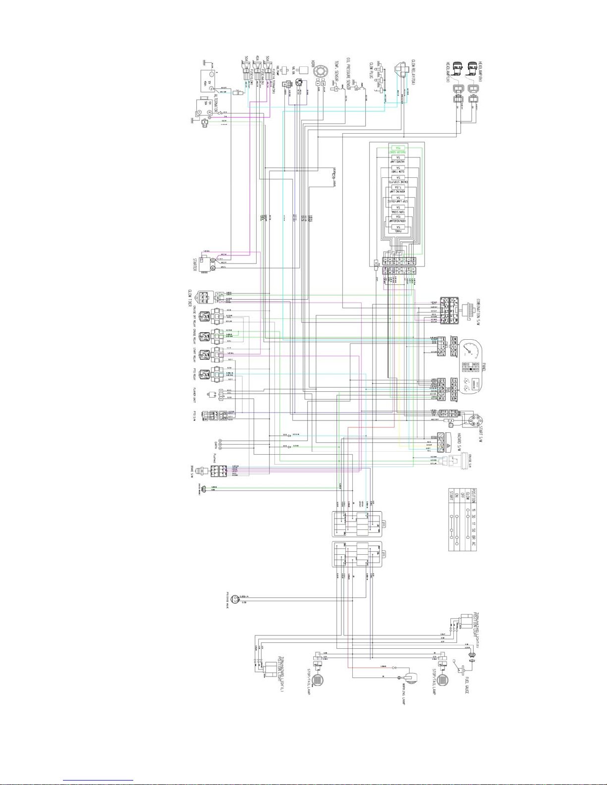
Wiring Diagram(A3)
88
Page 90

FUEL SAVING TIPS
(a)Cl
fil
Note:
If air cleaning system is not properly maintained, it will lead to early wear of piston rings
1) put the engine oil on load after the engine is heated & the water temperature gauge indicates
pg
To save fuel & oil in your tractor, following things should always be kept in mind.
A) Air cleaning system
1) Clean the air cleaner regularly so that dust does not settle down.
2) For every 50 hours & everyday in sandy/dusty conditions.
ean the air cleaner
ter element with compressed air.
(b) If the rubber ring is cut or expanded then change it with an appropriate one.
Fix the rubber at the proper location & check for leakages if any.
(c) If air is leaking through the hose connection, check & rectify other leakages, too.
& sleeves. This will lead to problems like loss of engine power,, excessive oil consumption
fuel consumption.
B) Engine
the needle to be in the green zone.
2) If excessive black smoke is visible, then the paper element of air cleaner, Fuel injection Pump
or nozzles should be checked.
3) Do not run the engine without load for more than 2 minutes. It is better to stop the engine
rather than run it idle. This will help in saving of fuel.
C) Clutch & Brakes.
1) Do not reduce the power of the power of the engine by depressing the clutch halfway. Instead
use low gear.
2) If the Tractor has to be stopped for a long period, it is advisable to bring the transmission in
neutral position & release the clutch pedal.
3) Do not over ride the clutch & brake pedals.
4) While coming down from a slope, reduce the engine throttle & use low gear. Do not depend
only on the brakes for stoppage.
89
Page 91

D) Fuel system
condensation
E) Lubricati
y
y
1) Always use filtered diesel for the fuel system
2) At the end of the day’s working, it is preferable to fill the diesel tank so that it may prevent
.
3) Change the filter, if the system gets choked. Do not change both the filters at the same time. If the
above directives are not adhered to, the fuel injection pump & injection nozzle will lose its life
early. Also, it will lead to excessive black smoke & excessive diesel consumption.
on system
1) Always use recommended grade of oil.
2) Everyday before starting the engine, check the oil level with a dipstick & refill between the
minimum & maximum level.
3) Charge the engine oil, Replace filter & “O” ring, as & when required.
F) Cooling system
1) Check the fan belt tension regularly. Adjust, If required.
2) Check the coolant level in the radiator fins always clean.
3) Replace the radiator cap with a genuine cap only, if required.
4) Do not remove the thermostat but replace with a new one, if required.
5) Do not change the radiator water often.
Note:
1) Always stop any fuel or oil leakages.
2) Carry out the regular maintenance failure to do so might increase the fuel consumption by 25%.
3) Carry out the torque of cylinder head bolt & adjustment of valve clearance regularly. Consult
our dealer for this.
4) Check the tire pressure & inflate, as recommended.
5) Always buy genuine spares from the authorized Dealer/Distributor.
6) Always carry out the service of the Tractor by your authorized Dealer/Distributor.
For any other information, contact your nearest Authorized Dealer/Distributor.
90
Page 92

TRACTOR HISTORY CARD
DATE JOB CARD
NO.
NATURE OF
DEFECT
PARTS REPLACEMENT W/CLAIM NO.
AND DATE
REMARKS
91
Page 93

SERVICE RECORD
DATE TRACTOR HOURS NATURE/TYPE OF REPAIR/SERVICE CARRIED OUT
92
Page 94

DAILY OPERATION LOG
START
END
DATE JOB DONE MACHINE HOURS FUEL
CONSUMPTION
ENGINE OIL
TOPPED UP
EMARKS
93
Page 95

PART REPLACEMENT RECORD
DATE PART
DESCRIPTION
QTY COST DATE PART DESCRIPTION QTY COST
94
Page 96

OPERATOR’S MANUAL FOR TRACTORS
T293HST
CODE NO.
1318 – 912 – 002 – 0
Printed on Nov. 2009
1st EDITION
95
 Loading...