


TYM
OPERATO R’S MANUAL
FOR
TRACTORS
T254NC
DaeYong B/D, 7, Eonju-ro 133-gil, Gangnam-gu, Seoul, Korea ■ TEL: 82-2-3014-2800, FAX:82-2-3014-2852 ■ www.tym.co.kr

YANMAR
WARRANTIES
YANMAR LIMITED WARRANTY
What is Covered by this Warranty?
YANMAR warrants to the original retai l purchaser that a new Y ANMAR TNV common rail series ind ustrial
engine will be free from defects in material and/or workmanship for the duration of the warranty period.
Note: YA N M AR engines may be equipped with ext e rnal components i nc ludi ng , but not l imited to: wir i ng
harnesses, electrical devices, control panels, radiator, air filters, fuel/or exhaust systems that are supplied
and/or inst a ll e d by manufa c t ure r s other than Y ANMAR . For war r a nty informat ion on suc h e x t e r na l
components , ple a s e cont a c t the machine or component m a nufacture r directl y or see your authoriz e d
YANMAR dealer or distributor .
This warranty is provided in lieu of all other warranties, express or implied. YANMAR specifically disclaims
any implied warranti es of merchantability or fitness for a particular p urpose, except where such disclaimer
is prohibited by law. If such disclaimer is prohibited by law, then implied warranties shall be limited in
duration to the life of the express warranty.
How Long is the Warranty Period?
The YANMA R standard lim ite d warra nty period runs for a period of twenty-four (24) months or
Two-thousand(2000 ) engine o peration hours, whichever occurs first. An extended limited warranty of
thirty-six(36) months or three thousand(3000) engine operating hours, whichever occurs first, is provided
for these specific parts only: the cylinder block, cylinder head, crankshaft forging, connecting rods,
flywheel, flywheel housing, camshaft, timing gear, and gear case. The warranty period for both the
Standard lim i ted warr anty and the extended lim ite d warr anty (by duration or operation hours) beg ins on the
date of delivery to the original retail purchaser and is valid only until the applicable warranted duration has
passed or the operation hours are exceeded, whichever comes first.
1

YANMAR limited warranty- continued
What the Engine Owner must Do:
If you believe your YANMAR engine has exp erienced a failure due to a defect in material and/o r
workmanship, your must contact an authorized YANMAR industrial engine dealer or distributor within thirty
(30) Days of discovering the failure, You must provide proof of ownership of the engine, proof of the date of
the engine purchase and deliv e r y, and docume nta t ion of the engine oper a ti on hour s . Accept a ble forms of
proof of delivery date include, but are not limited to: the original warranty registration of sales receipts or
other documents maintained in the ordinary course of business by YANMAR dealers and/or distributors,
indicating the date of delivery of the YANMAR product to the original retail purchaser, This information is
necessary to establish whether the YANMAR product is still within the warranty period. Thus, YANMAR
strongly recommends you registe r y our engine as soon as possible a fter purchase in orde r to facilit a te any
future warranty matters.
You are respons i ble for the trans por ta t ion of the engine t o a nd from the repair location as designated by
YANMAR.
To Locate an Authorized YAN MA R Industrial Engine Dealer or Distribut or:
You can locate your nearest authorized YANMAR industrial engine dealer or distributor by visiting the
YANMAR Co,. Ltd. Website at:
http://www.yanmar.co.jp (The Jap anese language page will be disp layed.) For English lan guage “click” on
“English Page.”)
● “click” on “Network” in the website heading to vies the “YANMAR Worldwide Network.”
● Choose and “Click” on the desired product group.
● “Click” on the Icon closest to your region.
● “Click” on the d es ired country or associate company to locate your nearest au thorized YANMAR
Industrial engine dealer or distributor.
You may also contact YAN MAR by clicking on “I nquir y” in the we bs it e heading a nd t yping in y our question
or comment.
What YANMAR will DO:
YANMAR warrants to the original retai l purchaser of a new YANMAR engine that YANMAR will make
such repai rs and/ or r e pl a c e ments at YAN MAR’s option, of any part(s) of the YANMAR product c ov e r e d by
this war r a nty found to be defec t ive in materia l and/or w or k manship. Such r e pa i rs and/ or r e pl a c e ments will be
made at a locat ion de s i g na t e d by YANMA R at no cost to the purc ha s e r for parts or labor .
2

YANMAR limited warranty- continued
What is no Covered by this Warranty?
This warranty does not cover parts affected by or damaged by ant reason other than defective materials or
workmanship, including, bur not limited to, accident, misuse, abuse, “Acts of God,” neglect, improper
installation, improper maintenance, improper storage, the use of unsuitable attachments or parts, the use
of contaminated fuels, the use of fuels, oils, lubricants, or fluids other than those recommended in your
YANMAR Operation Manual , una ut hor iz e d altera t ions or modifications, ordinary wear and tear , and r ust or
corrosion. This warr a nty does not cover the cos t of part s a nd/or labor require d to pe r form
normal/scheduled maintenance on your YANMAR engine. This warranty does not cover consumable parts
such as, but not limited to, filters, belts, hoses, fuel injector, lubricants and cleaning fluids. This warranty
does not cove r the cos t of shipping the produc t t o or form the war r a nty repair facil it y.
Warranty Limitations:
The foregoing is YANMAR’s only obligation to you and your exclusive remedy for breach of
Warranty
. Failure to follow the requirements for submitting a claim under this warranty may result in a
waiver of all claims for damages and other relief. In no event s hall YA NMAR or any authorized
Industrial engine dealer or distributor be liable for incidental, special or consequential damages.
Such conseque nti a l dama g e s may include, but not be lim i ted to, loss of reve nue, loan payments, cost of
rental of substitute equipment, insurance coverage, storage, lodging, transportation, fuel mileage, and
telephone costs. The limitations in this warranty apply regardless of whether your claims are based on
breach of contract, tort(including negligence and strict liability) or any other theory. Any action arising
hereunder must be brought w it hin one ( 1) y e a r aft e r the cause of ac ti on a c c r ue s or it sha ll be ba rr e d. S ome
states and countries do not allow certain limitations on warranties or for breach of warranties.
This
warranty gives you spe ci fi c legal righ ts , and you may also have other rights which vary form
state to state and country to countr y.
Limitations set forth in this paragraph shall not apply to the
extent that they are prohibited by law.
Warranty Modifications:
Except as modified in writing and signed by the parties, this warranty is and shall remain the complete and
exclusive agreement bet ween th e parties with respect to warranties, su p ersed in g all prior agreements,
written and oral, and all other communications between the parties relating to warranties. No per son or
entity is authorized to give any other warranty or to assume any ot he r obligation on behalf of
YANMAR, either orally or in writ ing.
Questions:
If you have any questions or concerns regarding this warranty, please call or write to the nearest
authorized YANMAR industrial engi ne de a le r or distr ibut or or other authorized fa c i li ty.
3

EMISSION SYSTEM WARRANTY
YANMAR CO. , LTD. LIMI TED EM ISS IO N CONTROL SYSTEM
WARRANTY – USA ONLY
Your W arranty Rights and Obligations:
■ California
The California Air Resources Board (CARB), the Environmental Protection Agency (EPA) and YANMAR
Co,. Ltd. hereafter referred to as YANMAR, are pleased to explain the emission control system warranty
on your industrial c om pres sion-ignition engine. In California, model year 2000 or later off-road
compression-igniti on e ngines mus t be desi g ne d, built a nd equipped to meet the state ’s str i ng e nt a nti-smog
standards. I n a ll sta te s , 1998 a nd la t e r non-road c om pre ss ion-ignition engines must be designed, built and
equipped to meet the United States EPA emissions standa r ds. Y ANMAR warr a nt s the emission control
system on your engine for the periods of time listed below provided there has been no abuse, neglect or
improper maintenance of your engine.
Your emis si on contr ol sys te m may include parts such as the fuel injection s ystem, the air induction system,
the electronic control system, EGR(Exhaust Gas Recirculation) system and Diesel Particulate Filter. Also
included may be hoses, belts, c onne c t ors a nd ot he r e mission-related ass embl ies.
Where a warrantable condition exists, YANMAR will repair your non-rod compres sion-ignition engine at
no charge to you inc ludi ng di a g nos i s , pa r ts a nd l a bor .
Manufacturer’s Warranty Period:
The model year 1998 or later certified and labeled non-road c om pre ss ion-ignition engines are warranted
for the periods listed below. If any emission-related part on your engine is found to be defective during the
applicable warranty period, the part will be replaced by YANMAR.
If your engi ne
is certified as
And its
maximum
Power is
And its
rated
speed is
Then its warranty period is
Variable speed or
Constant speed
kW<19 Any speed 1,500 hours or two (2) years whichever comes first.
In the abse nc e of a de v i ce to mea s ur e the ho ur s o f use,
The eng ine has a warranty period of two (2) yea r s .
Constant speed 19 ≤ kW < 37 3,000rpm o r
higher
1,500 hour s or two (2) years whicheve r comes f i r s t.
In the abse nc e of a device to measure the hours of use,
The eng ine has a warranty period of two (2) yea r s /
Constant speed 19 ≤ kW <37 Less than
3,000rpm
3,00hours o f five (5) years whichever comes first.
In the abse nc e of a de v i ce to mea s ur e the ho ur s o f use, the
Engine has a warranty period of five(5) years.
Variable speed 19 ≤ kW <37 Any speed 3,000 hours or five (5) y ears whichever comes first.
In the abse nc e of a de v i ce to mea s ur e the ho ur s o f use,
the engine has a warranty period of five (5) years.
Variable speed or
Constant spe ed
kW ≥ 37 Any speed 3,000 hours or (5) years whichever comes first.
In the abse nc e of a de v i ce to mea s ur e the ho ur s o f use,
The engine has a warranty period of five (5) years.
4

Limited emission control system warranty – USA only – continued
Warranty Coverage:
This warranty is transferable to each subsequent purchaser for the duration of the warranty period. Repair
or replacement of any warranted part will be performed at an authorized YANMAR industrial engine dealer
or distributor.
Warra nte d par ts not sc he dul e d for replacement as required maintena nc e in the oper a t ion manual shall be
warranted for the warranty period. Warranted parts scheduled for repl acement as required maintenance in
the operation manual are warranted for the period of time prior to the first scheduled replacement. Any part
repaired or rep laced under warranty shall be warranted for the remaining warranty period.
During the warranty period, YANMAR is liable for damages to other engine components caused by the
failure of any warrante d part duri ng t he warranty period.
Any replacement part which is functionally identical to the original equipment part in all respects may be
used in the m a int e na nc e or repa ir of y our eng i ne , and s ha ll not r e duc e YANMAR’s warranty obligations .
Add-on or modified parts that are not e x e mpted may not be used, The use of any non-exempted add-on or
modified parts shall be grounds for disallowing a warranty.
Warranted Parts:
This war r a nty covers engine components that a r e a part of the emission control syste m of the engine as
Delive red by YANMA R to the origina l r e t a il purcha s e r , S uc h c omponents may include the f oll owing:
● Fuel injection system
● Electronic control system
● Cold start enrichment system
● Intake manifold
●Turbocharger systems
● Exhaust manifold
● EGR system
● Positive crankcase ventilation system
● Hoses, belts, connectors and assemblies associated with emission control systems
● Exhaust gas after treatment (Diesel P ar ticu lat e Filter (DPF)
Since emissions-r elated parts may vary slightly between models, certain models may not contain all of
These parts and other m odel s may contain the functional equiva lent s.
5

Limited emission control system warranty – USA only – continued
Exclusions:
Failures ot he r tha n t hos e a r is ing from defec t s in ma t e r ia l and/or w or kmanshi p are not covered by this
warranty. The warranty does not extend to the following: malfunctions caused by abuse, misuse, improper
Adjustment, modification, al te r a t ion, ta mpering, disconnection, improper or inadequate maintenance or use
Of non-rec ommended fuels and lubrica ti ng oil s ; a ccident-caused damage, and replacement of expendable
Items made in connection with scheduled maintenance. YANMAR disclaims any responsibility for
Incidental or consequential damages such as loss of time, inconvenience, loss of use of equipment/engine
Or commercial loss.
Owner’s Warranty Responsibilities:
As the engine owner, you are responsible for the performance of the required maintenance
listed in Your owner’s manual.
YANMAR recommends that you retain all documentation, including
receipts, covering maintenance on your non-road c ompre ssion-ig niti on eng ine, but YANM A R cannot deny
Warranty solel y for the lack of receipts, or for your failure to ensure the perfo r mance of all sched uled
maintenance.
YANMAR may deny your warranty coverage of your non-road com pr ess ion-ignition engine if a part has
Failed due to a bus e , neg l e c t, im pr ope r m a i nte na nc e or unapproved modifications.
Your engine is designed to operate on diesel fuel only. Use of any other fuel may result in your engine no
Longer operating in compliance with applicable emissions requirements.
You are responsible for initiating the warranty process. You must present your engine to a YANMAR dealer
As soon as a problem exists. The warranty repairs should be completed by the dealer as expeditiously as
Possible. If you have any questions regarding your warranty rights and responsibilities, or would like
Inform a t ion on the ne a rest YANMAR dealer or authorize d s e r v ice center, y ou should c ont a c t YANMAR
America Corporation.
Website: (www.yanmar.com)
E-mail: CS support @yanmar.com
Toll fre e telephone number: 1-800-872-2867, 1-855-416-7091
6

FORWARD
Thank you very much for purchasing our tractor, which, we are sure, will give you many years of
trouble free service.
This manual introduces you to the correct manner of operating, maintaining and repairing
the tract or to e ns ure long -term durability.
Please ensure the correct operati on of the tractor as incorrect operation can cause substantial
mechanical damage as well as accidents with associated injuries.
Also, please note that in some cases, differences may exi s t between this manual and the specifics of your
tractor due to t he manufacture’s policy of consta nt pr oduc t i mprovement.
In the event that you encounter a problem not covered by this manual, please contact your nearest dealer
who will assist you in resolving it.
WARNING
CALIFORNIA Proposition 65 Warning
The Engine Ex ha us t from this product c onta i ns c he micals known to the
state of California to cause cancer, birth defects or other reproductive harm
WARNING SIGNS IN THIS MANUAL
The following warning signs in this manual draw additional attention to items of importance for the
safe and correct operation of the tractor.
SIGN MEANING
Serious hazard with a very high level of risk of either serious injury or death
Hazard or un s afe practice that can lead to severe injury or death.
Hazard or un s afe practice that can lead to injury or death.
Instructions for the correct operation of the machine which,
if followed, will ensure that it performs at its best
All information, illustrations and specific ations in this manual are based on the latest information
available at the time of publication.
The right is reserved to make changes at any time without notice.
7
Caution
Danger
Warning
Important

CONTENTS
1. Tractor Identification ---------------------------------------------------------------------------------
2. About this Manual -------------------------------------------------------------------------------------
3. Introduction & Description ---------------------------------------------------------------------------
4. Owner Assistance --------------------------------------------------------------------------------------
5. ROPS (Roll Over Protection Structures) ------------------------------------------------------------
6. Safety Instructions, Do’s & Don’ts -----------------------------------------------------------------
7. Safety Signs --------------------------------------------------------------------------------------------
8. Universal Symbols -------------------------------------------------------------------------------------
Section A
9. Controls, Instruments & Operations ----------------------------------------------------------------
Section B
10. Lubrica ti on & Mai nte na nc e ------------------------------------------------------------------------
Section C
11. Specifications -----------------------------------------------------------------------------------------
12. Fuel Saving Tips --------------------------------------------------------------------------------------
13. Fault tracing --------------------------------------------------------------------------------------------
13. Wiring Diagram --------------------------------------------------------------------------------------
14. Tractor History Card ---------------------------------------------------------------------------------
15. Service Record -----------------------------------------------------------------------------------------
16. Daily Operating Log -----------------------------------------------------------------------------------
17. Part Replacement Record ------------------------------------------------------------------------------
Sr. No. Description Page N o.
All information, illustrations and specifications in this manual are based on the latest information available
at the time of publication. The right is reserved to make changes at any time without notice.
8
9
10
11~12
13
14~16
17~29
30~32
33
34~53
54~73
74~78
79~80
81~84
85~86
87
88
89
90

TRACTOR IDENTIFICATION
The engine number is stamped on the left hand side of the engine block.
The chassis number is shown on the left hand side of the tractor as shown in the drawing.
Illustration A
WARRANTY OF THE PRODUCT.
The manufacturer warrants this product and the full details of the warranty are provided on a separate
warranty schedule.
SERVICE.
Service is available from any TYM dealer in the country.
PARTS.
To obtain spare parts, please contact your nearest dealer and give them the details listed below.
•Tractor model
•Tractor serial number
•Tractor engine number
•Part number and description
•Quantity required.
Stamped position of the
Engine type or Number
Stamped position of the chassis number
9

ABOUT THIS MANUAL
This manual has been prepared to assist you in following/adopting the correct procedure for operating
and maintaining your new Tong yang Moolsan CO.,LTD (Here in after refer to TYM) Tractor..
Your tractor has been designed and built to offer maximum performance with good fuel economy and
ease of operation under a wide variety of operating conditions.
Prior to delivery, each tractor is carefully inspected, both at the factory and by your TYM
dealer/distributor, to ensure that it reaches you in optimum condition.
To maintain this condition and ensure trouble free performance, it is important that the routine
services, as specified in this manual, are carried out at the recommended intervals.
Read this manual carefully and keep it in a convenient place for future reference.
If at any time you re quir e a dvice concerning your tra c tor , do not he s it a te to contact your authorized
TYM deale r/ dis t r ibut or who has tra i ne d pers onne l , genuine par ts and the necess a r y equipment to
undertake all your service requ irements.
TYM policy is continuously improved, and TYM reserves the right to change prices, specifications or
equipment at any time without notice.
All data given in this book is subject to production variations.
Dimensions and weight are approximate only and the illustrations do not necessarily show tractors in
standard condition.
For exact information about any particular tractor, please consult your TYM dealer/distributor.
10

Introduction & Descriptio n
► INTRODUCTION
The word, “Tractor”, was been derived from “Traction”, which means pulling.
A tractor is required to pull or haul equipment, an implement or trolley which is coupled to the
tractor body through a suitable linkage.
A tractor can also be used as a prime mover as it has a power outlet source, called the Power Take
or PTO shaft.
This manual complies the operation, maintenance and storage instructions for all models of TYM
Diesel tractors.
It has been prepared to help you in the better understanding of the maintenance and efficient operation
of the machine.
If you need any informat ion not provided in this manual, or require the services of a trained mechanic,
please get in touch with your local TYM dealer/distributor.
Dealer/distributors are kept informed of the latest metho ds of servicing tractors.
They stock genuine spare parts and are backed by the Company’s full support.
Through this manual, the use of the terms
LEFT, RIGHT, FRONT and REAR must be
understood to avoid any confusion when
following the introductions.
The LEFT and RIGHT means the lef t and rig ht s i de s
of the tractor when facing forward in the driver’s seat.
Reference to the FRONT indicates the radiator end of the
tractor, while the REAR indicates the drawbar end
(Illustration B).
When spare parts are required, always specify
the tractor and engine serial number when
ordering them (See illustration A).
This will facilitate a faster delivery and help ensur e
that the correct parts for your part icular
tractor are received .
The tractor serial number is stamped on a plate
attache d to the l e ft hand side of the eng i ne body
(Illust. A).
For easy reference, we suggest that you write the number
in the space provided in the ow ne r ’ s pers ona l da ta .
Illustration A
( Front, R e a r , L e ft, and Right Portion)
11

► DESCRIPTION
■ General Construction
The transmission case, engine and front axle support are bolted together to form a rigid unit.
■ Front Axle & Wheels
The 4WD front axle is a center-pivot, reverse Eliot type.
The front wheel drive mechanism is incorporated as a part of the axle.
The drive power of the front wheels is taken from the rear transmission and transmitted to the
differential in the front axle where the power is divided into right and left and to the respective final
cases.
In the final cases, the transmitted revo lution is reduced by the level gears to drive the front wheels.
The 4WD mechanism with level gears provid es wider steerin g and greater dur abi lit y.
■ Engine
The tractors are fitted with fuel efficient engines with 3 cylinders manufactured by Yanmar.
■ Clutch and Transmission
A single plate dry clutch is used on these tractors.
Tractors with IPTO(Independent Power Take Off) are fitted with hydraulic clutch assy.
The transmission Gear box has six forward speed & two reverse speeds with a high-low select lever.
Presently, TYM tractors are fitted with sliding gear and constant mesh type gears.
■ Brakes
TYM tractors are provided with disc brakes operated by a foot pedal.
A parking brake lever is fitted for parking.
■ Rear axle & Wheels
This is mounte d on ba l l bearings and is enc los e d i n re movable housing which are bolte d t o the
transmission case.
The rim & disc, fitted with rear tires are bolted to the out er flange of the rear axle.
■ Hydraulic System & Linkages
TYM Tractors are fitted with live (i.e. system is in operation) independent systems.
Three point Linkages can be used for category 1(N) type of implements.
■ Steering
Steering consists of a Hydrostatic Power Steering system, which has a hydraulic cylinder and a single
type hydraulic pump
■ Electrical System
A 12 volt battery is used to activate the engine through the starter motor and the electrical system
comprising the horn, head lamp, turn signal lamp, tacho-meter, hour meter, brake lamp, gauge lamp,
hazard lamp and general or alternator, fuse box which is also from the electri cal system.
12

OWNER ASSISTANCE
We at TYM and your TYM dealer/distributor would like you to be completely satisfied with
your investment.
Normally any problems with your equipment will be handled by your dealer/distributor’s service
departments.
If however, you feel that your problem has not been handled to your satisfaction by the
local dealer/distributor, we suggest the following:
Contact the owner or General Manager of the dealership, explain the problem, and request assistance.
When additional assistance is needed, your dealer/distributor has direct access to our office.
If you cannot obta in satisfaction by doing this, contact t he TY M off ice and
provide the m with;
• Your name, address and te l e phone number
• Model and t r a c tor se ri a l num be r
• Dealer/Distributor Name & Address
• Machine pur c ha s e date a nd hours us e d
• Nature of problem
Before the contacting TYM office, be aware that your problem will be likely resolved at
the dealership using the dealer’s/distributor’s facilities, equipment and personnel.
So it is important to seek assistance first with the dealer/distributor.
13

(ROPS) Roll Over Protect ive Structures
► ROLL OVER PROTECTIVE STRUCTURES (ROPS)
TYM Tractors are equipped with a frame that protects its operator.
The frame is incorporated in the cab str ucture in the case of cab tractors.
The objective of the frame or cab structure is to protect the operator in the event of a roll over and to
support the e nt ir e w e i g ht of the tra ctor.
Each TYM ROPS frame or cab structur e , a s wel l as all m ount ing bases and bol ts or othe r
faste ne r s , is desig ne d a nd has been teste d to meet industry and or g overnme nt standa rds .
DANGER
For ROPS frames to protect the operator effectively, the provided seat belt must be
worn in order to keep the operator within the ROPS protected area in the event of a roll over.
Failure to use the seat belt can cause serious injury or death.
On some models the ROPS frame has a fold down feature, which can be used to enter low
buildings etc.
Take care when lowering the upper section of the ROPS frame and take extreme care while
driving the tractor with the ROPS frame lowered.
Do not wear the seat belt with the ROPS lowered, and please remember that the fold down facility
is for special circumstances only and no for general use.
Use of the tractor with the ROPS lowered can cause fatal injuries.
As the ROPS frame or cab together with the seat belt was designed to meet certain standards,
they must be m a int a ined in good order and c ondi ti on.
To achieve this objective, both the structure and the seat belt should be inspected on a regular
basis (every time t he tractor is serviced) .
In the event that the seat belt is damaged or frayed, it should be replaced, and in the event that th e
ROPS frame or any part of the mounting structure is damaged or cracked, the faulty component
must be replaced with a new unit.
Any replacement unit must meet all of the test criteria of the original unit.
Fitment of an inferior item or items affects the certification of the entire ROPS structure and the
effectiveness of the structure in the event of an accident.
Drilling or welding the ROPS structure is forbidden.
14

► DAMAGE OF THE ROPS
If the tract or has r oll e d ov e r or the R OPS ha s bee n da maged (such as striking an over he a d objec t during
transport), t he ROPS must be replac e d to prov i de the or i g i na l pr ote ction.
After an accident, check for damages t o 1. ROPS; 2. Seat; and 3. Seat belt & seat mountings.
Before you operate the tractor, repl ace all damaged par ts.
► DO NOT WELD, DRILL OR STRAIGHTEN THE ROPS
Never attach chains or ropes to the ROPS for pulling purposes; this will cause the
tractor to tip backwards.
Always pull from the Tractor drawbar. Be careful when driving through door
openings or unde r low overhead obje c ts . M a k e sure
there is sufficient overhead clearance for the ROPS to avoid fatal injuries.
If the ROPS is removed or replaced, make certain that the proper hardware is
used to repla c e the RO PS and the recommende d torque v a lue s are applie d t o
the attaching bolts.
Always wear your seat belt if the tractor is equipped with ROPS.
Warning
Warning
Warning
15

Check whether the seat is proper ly locked in its positi on before driving the tra c t or.
Alway s use the seat belt when the ROPS is installed. Do not use the seat belt if a
foldable ROPS is down or there is no ROPS.
Check the seat bel t regularly and repl ace if it is frayed o r damaged.
Danger
Danger
16
► FOR SLIDING SEAT
■ Sliding Seat type
Slide the seat to the position you want. Release the lever.
Make sure the seat is locked in position.
NOTE: Do not use solvents to clean the sea t.
Use warm water with a small amount o f d etergent added.
Before operating the tractor it is important to adjust the seat to the most comfortable position
and check whether it is properly locked in position.
Figure 1 identifies the seat fitted to your tractor.
* Sliding type
How to adjust the seat

SAFETY INSTRUCTIONS
SIGNAL WORDS.
A signal word―DANGER, WARNING OR CAUTION―is used
with a safety alert symbol. DANGER identifies the most serious
hazards. Safety signs with the signal words ―DANGER OR
WARNING―are typically near specific h azards. General
precautions are listed on CAUTION safety signs.
READ SAFETY INSTRUCTIONS
Carefully read all safety instructions given in this manual for your
safety. Tampering with any of the safety devices can cause serious
injuries or death. Keep all safety signs in good condition. Replace
missing or damaged safety signs.
Keep your tra ctor in proper condit ion and do not allow any
unauthorized modifications to be ca r r ie d out on the t ractor, whic h
may impair the fun ction/safety an d affect tractor life.
CHILD PROTECTION
Keep childre n a nd ot he rs a way from the trac tor w hil e oper a ti ng .
BEFORE YOU REVERSE
- Look behind the tractor for children.
- Do not let childr e n r ide on t he tr a c t or or any implem e nt.
RECOGNIZE SAFETY INFORMATION
This symbol means ATTENTION! YOUR SAFETY IS INVOLVED.
The message that follows the symbol contains important information
about safety. Carefully read the message.
17
DANGER
WARNING
CAUTION

USE OF ROPS AND SEAT BELT
The Roll Over Protective Structure (ROPS) has been certified to
industry and/or g overnme nt standa r ds. Any damag e or alterna t ion t o
the ROPS, mounting hardware, or seat belt voids the certification and
will reduc e or el iminate protection for the opera t or i n the event of a
rollover. T he RO PS, mounting hardware, and sea t belt shoul d be
checked after the first 100 hours of tractor use and every 500 hours
thereafter for an y evidence of damage, wear or cracks. In the event of
damag e or alter a t ion, the ROPS must be replaced prior to furthe r
operation of the tractor.
The seat belt must be worn during operation when the machine is
equipped with a certified ROPS.
Failure to do s o will reduce or eli minate protection for the oper a t or i n
the event of a rol lover.
PRECAUTION TO AVOID TIPPING
Do not drive where the tractor could slip or tip.
Stay alert for holes and rocks in the terrain, and other hidden
hazards.
Slow down before you make a sharp turn.
Driving for ward out of a ditch or m i red condition could c a us e the
tractor to tip over backward. Back out of these situations if possible.
PARK TRACTOR SAFELY
Before working on the tractor,
lower all equipment to the ground and
stop the eng ine and r e move the key .
KEEP RIDERS OFF TRACTOR
Do not allow ride r s on the tr a c t or.
Riders on the tra c tor a r e subjec t t o inj ur ie s s uc h a s being stuck by
foreign objects or being thrown off of the tractor.
18

HANDLE FUEL SAFELY-AVOID FIRES
Handle fuel with care; it is highly flammable. Do not refuel the
tractor while smoking or near open flame or sparks.
Always stop the engine before refueling the tractor.
Always keep your tractor clean of accumulated grease, and debris.
Always clean up spilled fuel.
STAY CLEAR OF ROTATING SHAFTS
Entanglement in rotating shaft can cause serious injury or death.
Keep the PTO shield in place at all times.
Wear close fitting clothing. Stop the engine and make sure that
the PTO drive is stopped before making adjustments, connections,
or cleaning out PTO drive n equipment.
ALWAYS USE SAFETY LIGHTS AND DEVICES
The use of hazard warning lights and turn signals is recommended
when towing equipment on public roads unless prohibited by state or
local regulations.
Use the slow moving vehicle (SMV) signs when driving on public
roads during both da y & night time , unless pr ohibi te d by law.
PRACTICE SAFE MAINTENANCE
Understand the service procedure before doing work.
Keep the surrounding area of the tractor clean and dry.
Do not attempt to service the tractor when it is in motion.
Keep body parts and clothing away from rotating shafts.
Always lower equipment to the ground. Stop the engine.
Remove the key. Allow the tractor to cool before any repair work
is to be performed.
Securely support any tractor elements that must be raised for
service work.
Keep all parts in good condition and properly installed.
Replace worn or broken parts. Replace damage/missing decals.
Remove any buildup of grease or oil from the tractor.
Disconnec t the batter y ground cable (−) before making adjustments on
electrical systems or welding o n the tractor
19

AVOID HIGH-PRESSURE FLUIDS
Escaping fluid under pressure can penetrate the skin causing serious
injury. Keep hands and body away from pinholes and nozzles, which
can eject fluid under high pressure. If any fluid is injected into the
skin,
consult y our doctor im m edia te ly .
PREVENT BATTERY EXPLOSIONS
Keep sparks, lighted matches, and open flame away from the top of the
battery. Battery gas can explode.
Never check the battery by placing a metal object across the poles .
PREVENT ACID BURNS
Sulfuric acid in battery electrolyte is poisonous. It is strong enough to
burn skin, cause holes in clothing and blindness if made contact
with eyes.
For adequate safety always;
1. Fill batteries in a well-ventilated area.
2. Wear eye protection and acid proof hand gloves.
3. Avoid breathing direct fumes when electrolyte is added.
4. Do not add water to electrolyte as it may splash up, causing severe
burns.
If you spill acid on yourself;
1. Flush your skin with water.
2. Flush your eyes with water for 10-15 m inute s.
3. Get medical attention immediately.
SERVICE TRACTOR SAFELY
Do not wear a necktie, scarf or loose clothing when you work near moving
parts. If these items were to get caught, severe injury will result.
Remove rings and other jewelry to prevent electrical shorts and entanglement
in moving parts.
20

The Safety Starter Switch should be replaced after every 2000 hours or 4 years,
whichever is earlier.
TRACTOR RUNAWAY
1. The tractor can start even if the transmission is engaged, thus causing the tract or to move
and result in serious inj ury to the people s t a nding nearby the tractor.
2. For additional s a fety, keep the transmiss i on in neutr a l , foot brake eng a g e d and the PT O lever
disengaged while atte nding to Safe ty Starter Switc h or a ny other work on the tra c t or.
SAFETY STARTER SWITCH
1. A clutch operated safety switch is provided on all tractors which allows the starting system to
become operational only when the clutch pedal is fully pressed.
2. Do not bypass this safety starter switch or wor k on it. Only authorize d de a le r s are
allowed to work on the safety starter switch.
3. On some mode ls , a saf e ty starter switc h is prov ide d on the transmission high-low shifter lever and
on PTO shifter lever. The tractor can be st ar ted only if the high-lo w shifter lever is in neutral.
WORK IN VENTILATED AREA
Do not start the tr a c t or in a n encl os e d buil ding unless the doors and
windows are open for proper ventilation, as tractor fumes can cause
sickness or death. If it is necessary to run an engine in an enclosed area,
remov e the exha us t fumes by connecting a n e xhaust pipe extension.
Caution
21

SAFE OPERATION OF YOUR TRACTOR
The manufacturer of your tractor has made every effort to make it as safe as is humanly possible.
Beyond this poi nt it is the respons i bil it y of the operator to avoid ac c i de nts and we ask that you rea d
and follow our recommendations for your safety.
Ensure that onl y traine d a nd c ompetent operat ors us e t he tr act or and tha t t hey are ful l y
conversant wi th the machine and aware of all of its control and safety features.
Operators should not operate the tractor or as s oc i a te d m achinery while tired or untraine d.
To avoid accidents, please ensure that the operator wears clothing which will not get entangled in the
moving parts of the tractor or machine as well as protect him or her from the elements.
When spraying or using chemicals, please make sure to wear protective clothing and protective
equipment that prevent r e s pir a tor y or skin problem s .
For full details consult the manufacturer of the chemicals.
To avoid lengthy exposur e to noise, wea r ear protect ion.
If adjustments to the tractor or machinery need to be made, ensure that the tractor or machine is
turned off beforehand.
The use of a certified Roll Over Pr otection Structur e (ROPS) is a must while operating a tractor.
The use of a seat belt is a must while op er ating a tractor.
In summary, ensure at all times that the safety of the operator and any other worker is paramount.
22

SAFETY TIPS DURING MAINTENANCE
1. Check all oil levels, water level in the radiator and electrolyte level in the
battery at least on ce a day, and perform services according to the service schedule.
2. Ensure that tire pressures are even and the correct pressure for the job to be performed is maintained.
3. Check to ensure that all the controls and preventative mechanisms of the tractor and implement
work correctly and effectively.
4. Ensure that an adequate set of the correct t ools is available for main tenance and minor repairs.
5. Ensure that all service work and repairs are carried out on a flat area with a concrete or similar
floor.
Do not carry out service work on the tractor until it is switched off, the parking brake applied
and wheels chocked.
Where t he tractor is op er ated in a confined area, ensure that the area is well ventilated as exh aust
gases are very harmful and can cause death .
6. Do not wor k under r a i s e d im pl e ments.
7. When changing wheels or tires, ensure that a suitable wheel stand is placed under the axle prior
to removing the wheel and the wheels are chocked.
8. Where gua r ds or shi e lds nee d t o be removed to perform a service or repa i r, ensur e t ha t t he
guard or shield is correctly reinstalled before starting the tractor.
9. Never refuel near an open flame or with an overheated engine.
Make sure to turn off the engine before refueling.
10. The cooling system operates under pressure; take care when removing the radiator cap on a
hot engine to prevent scalds by steam or hot water.
Do not add w a t e r to the radia t or when the engine is hot.
Add wa te r to the radiator only after the engine cooled down completely.
11.To prevent fires, keep the tracto r , including the engine, clean and free fro m flammable material
and away from fuels and other flammable material.
23

► MOUNTING AND DEMOUNTING IMPLEMENTS
(1) Ensure tha t all mounting and removal of imple ments is done on a safe flat ground.
Ensure no one is be t ween the tractor a nd implement to avoid accide ntal injuries, do not get under
the implem ent.
(2) After mounting the implement, ensure that all sway chains are correctly adjusted and, if a PTO
shaft is used, that the shaft is fitted and secured correctly.
(3) Where heav y impleme nts are used, e ns ur e that the c ombination is well balanced or us e proper
ballast to achieve balance.
(4) Before leaving the tractor at any time, lower the implement, stop the PTO shaft where
applicable, set the parking brake and switch off the engine.
(5) While opera t ing t he impleme nt s with the PTO , keep all bys t a nde r s awa y from any moving parts
and do not a tt e mpt to make adjustments whil e the m a c hi ne is running.
(6) Only the driver should ride on the tractor with the ROPS frame fitted and with the seat belt
properly fastened.
(7) Where young children are present, particular care should be taken and the tractor should not be
in operation until the whereabouts of all children is known.
(8) Only traine d ope r a tor s s hould operate t he tra c t or a nd care must be tak en to ensure that other
workers are not injured.
In particular the operator should take care during dusty operations, which will reduce visibility
substantially.
(9) Never start the tractor unless the transmission is out of gear, the operator is in the seat and all
around safety has been checked.
(10) Only operate the tractor seated in the drivers seat and never turn or brake suddenly at high
speed as this can cause a r oll-over and ser ious i njur y or death.
(11) When traveling on a public road ensure that the tractor and driver both meet all laws relating to
safety and licensing.
When traveling with wide i mpl ement ,s use red flags on the extremities and observe all laws
including e scor t require m ents .
(12) When opera t ing under adverse conditions , on a hilly terrain or on uneve n g r ound, adjust the spee d
of the tractor to suit the conditions, safety comes first.
Nev e r drive down hill at high spe e d or w i th the tr a ns mission in neutral.
Use the braking capacity of the engine as well as the service brakes.
Do not try to change gear going up or down a steep slope, select the correct gear before starting.
(13) Tak e care whe n tra v e l ing uphill with a heavy implement to ensure that i t does not ov e r ba la nce
and tip up the front end.
(14) Never remove or modify the seat belt.
(15) Never remove, modify or repair the ROPS frame.
PLEASE REMEMBER THAT A LITTLE BIT OF EXTRA CARE CAN PREVENT SERIOUS
INJURY OR DEATH AND AVOID DAMAGE TO YOUR TRACTOR.
24

► THE FOLLOWING PRECAUTIONS ARE SUGGESTED TO HELP PREVENT ACCIDENTS.
A careful operator is the best operator.
Most accidents can be avoided by observing certain precautions .
Read and tak e the f oll owing precautions be fore operating t he tr a c t or to pre v e nt accidents.
Tractor s should be operated only by those who are re spons i ble and properly trained to do so.
■ The Tractor
1. Read the operator’s manual carefully before using the tractor.
Lack of operatin g kno wledge can lead to accidents.
2. Use an approved rollover bar and seat belt for safe operation.
The overturning of a tractor without a rollover bar can result in death or injury.
3. Do not remove the ROPS (Roll Over Protective Structure).
Always use the seat bel t.
4. A fiberglass canopy does not give any protection.
5. To prevent falls, keep and platform clear of mud and oil.
6. Do not perm i t any one but the operator to r i de on the t ractor.
There is no safe place for extra riders.
7. Replace all missing, illegible or damaged safety signs.
8. Keep safety si gns clean of dirt and grease.
■ Servicing the tractor
1.Keep the tra c t or in good operating c ondi ti on for your safety .
An improperly maintained tractor can be hazardous.
2. Stop the engine before performing any service on the tractor.
3. The cooling s ystem operates under hig h pr e s s ur e , which is controlled by the radia t or c a p.
It is dangerous to remove t he cap while the system is hot.
Turn the cap slowly first to allow the pressure to escape before removing the cap entirely.
4. Do not smoke w hile the refueling the tractor. K eep aw ay any type of open flame.
5. The fuel in the inje c t ion s ystem is under high pressure and c a n pene tr a t e the s k i n.
Unqualified persons s houl d not remove or attempt to adjus t a pum p, inje c tor , nozzle or any part of the
fuel injection system.
Failure to follow these instructions can result in serious injury.
6. Keep open flame or cold weather starting aids away from the battery to prevent fire or explosions.
7. Do not modify or permit any one els e to modify t he tract or or any of its components or tractor
functions.
25

■ Operating the tractor
1. Before starting the tractor, apply the parking brake, place the PTO (Power Take Off) switch in the
“OFF” posit ion, the hydraulic control le vers in the neutr a l pos i ti on, t he r e mote control valve
levers in the neutral position( if fitted) and the transmission in neutral.
2. Do not sta rt the e ngine or operate the tr a c t or w hi le standing beside the tr a c t or.
Always sit in the tractor seat when the engine is running or when operating controls.
3. Safety starter switch.
In order to prevent the accidental starting of the tractor, a safety swi tch has been provided.
The starting system of the tractor is connected through this switch, which becomes operative only
when the brake pedal is depressed.
On som e mode ls , the shuttl e s hifter lever and PTO button should a l s o be in neut ra l pos it ion for
completing the starting circuit.
Do not bypass the safety starter switch.
Consult your TYM Tractor dealer/distributor if the safety starter switch malfunctions.
4. Avoid accidental contact with the gear shifter lever while the engine is running.
Unexpected tractor movement can result from such contact .
5. Do not ge t of f or climb around the tr a c tor w hi le it is in motion.
6. Shut off the engine, remove the key and apply the parking brake before getting off the tractor.
7. Do not opera te the tractor in an e nc l os e d building without adequate ve nti la t ion.
Exhaust fumes can cause death.
8. Do not park the tr a c tor on a ste e p slope .
9. If power steering or the engine ceases to operate, stop the tractor immediately.
10. Pull only from the sw inging draw bar or the lower link drawbar in the down pos it ion.
Use only a drawbar pin that locks in place.
Pulling from the tractor rear axle carriers or any point above the rear axle may cause the tractor’s
front end to lift.
11. If the front end of the tract or te nds to r is e w he n hea vy implements are attac he d to the thr e e -point
linkage, install front end or front wheel weights.
Do not opera te t he tra c t or with a light front e nd.
12. Always use the hydraulic position control lever when attaching equipment/implements and when
transport ing equipm e nt.
Be sure that the hydraulic couplers are properl y mounted and will disconnect safe ly in case when an
implement accidentally detach es.
13. Do not leave equipment/ im ple m ents in the raised position.
14. Use the f la s he r , turn signal light s and Slow Moving Vehic le ( SM V) s igns when drivi ng on publ ic
roads during both day and night tim e , unless prohi bit e d by law.
15. Dim tractor lights when meeting oncoming vehicles at night.
Be sure the lights are adjusted to prevent them from blinding oncoming vehicle operators.
16. Eme r g e nc y stopping instruction; If the tractor fails to stop e v e n after the applica ti on of brakes.
26

■ Driving the tractor
1. Watch where you are going especially at row ends, on roads, around trees and low hanging obstacles.
2. To avoid upsets, drive the tractor with car e and at speeds compati ble with safety, es pecially
when operating over rough ground, crossing ditches or slopes, and when turning at corners.
3. Lock the tra c t or bra k e peda l s toge t he r when transporting on r oa ds t o provide proper wheel braking.
4. Keep the tractor in the same gear when going downhill as is used when going uphill. Do not coast
or free wheel down hills .
5. Any towed vehicle and/or trailer whose total weight exceeds that of the towing tractor, must be
equipped with its own brakes for safe operation.
6. When the tractor is stuck or tires are frozen to the ground, back out to prevent upset.
7. Always check the overhead clearance, esp eciall y when tran spo rt in g the tractor.
■ Operating the PTO (Power Take Off)
1. When opera t ing PTO drive n equi pment, shut off the engine and wait until the PTO s t ops be fore
getti ng of f the tractor and dis c onne c t ing t he e qui pment.
2. Do not we a r loose clot hing whe n operati ng t he power take-off or near rotating e quipment.
3. When operating stationery PTO driven equipment, always apply the tractor parking brake and
block the rear wheels from the front and rear side.
4. To avoid injury, always move down the flip part of the PTO.
Do not cle a n, adjus t or service PTO drive n e qui pment when the tractor engine is runni ng .
5. Make sure the PTO master shield is installed at all times and always replace the PTO shield cap
when the PTO is not in use.
■ Diesel fuel
1. Keep the equipment clean and properly maintained.
2. Under no ci r c umstances should gasoline, a l c ohol or bl e nde d fuels be added to die s e l fue l .
In a closed container, s uc h a s a fue l tank, s uc h ble nds a r e more expl os ive than pure g a s oli ne .
DO NOT USE THESE BLENDS.
3. Never remove the fuel cap or refuel the tractor with the engine running.
4. Do not sm oke while refue l ing or when standing near fuel.
5. Maintain control of the fuel filler pipe when filling the tank.
6. Do not fill the fuel tank to full capacity. Allow room for expansion.
7. Wipe up spilled fuel immediate ly.
8. Always tighten the fuel cap securely.
9. If the original fuel tank cap is lost, replace it with a genuine cap.
A non approved cap ma y not be safe.
10. Do not drive equipment near open fire.
11. Never use fuel for cleaning purposes.
12. Arrange fuel purchases so that winter grade fuel is not held over and used in the spring.
N.B.: It is suggested that after repairs, if any of the Safety Decal/signs are peeled/defaced, the
same may be replaced immediately in the interest of your safety.
27

DO’S AND DON’T’S
► DO’S-For Better performance
DO-Ensure that safety shields are in place and in g ood c ondi ti on.
DO-Read all operating instructions before commencing to operate the tractor.
DO-Carry out all maintenance tasks without fail.
DO-Keep the air clean er clean.
DO -Ensure that the c or r e c t gra de of lubricating oi ls a r e use d a nd tha t they are replenishe d and
changed at the recommended intervals.
DO-Fit new sealing rings when the filter elements are changed.
DO-Watch the oil p ressure gauge or warning light and in vestigate any abnormality immediately.
DO-Keep the radiator filled with clean water, and in cold weather, use an anti-freeze mixture. Drain
the system only in an emergency and fill it before starting the en gi ne.
DO-Ensure that the t ra ns mission is in neutral before starting the eng ine .
DO-Keep all fuel in clean storage and use a fil ter when fillin g t he tank.
DO-Attend to minor adjustments and repairs as soon as they are required.
DO-Allow the engi ne to cool before removing the radiator fille r cap and a dding wate r , remove the
radiator cap slowly.
DO-Shift into low gear when driving down steep hills.
DO-Latch the brake pedals together when driving on a highway.
DO-Keep the draf t contr ol l e v e r f ull y down when not in use.
Don’ts-For safe operation
DON’T-Run the engine with the air cleaner disconnected.
DON’T-Start the tra c tor in an enc l os e d buil ding unless the door s a nd windows are open for proper
ventilation.
DON’T-Operate the tractor or engine while lubrica t ing or clea ning .
DON’T-Allow the tractor to run out of diesel fuel otherwise it will be necessary to vent the system .
DON’T-Tamper with the fuel injection pump; if the seal is broken, the warranty becomes void.
DON’T-Allow the engine to run i dle for a long period.
DON’T-Run the engine if it is not firing on all cylinders.
DON’T-Ride the brake or clutch pedal. This will result in the excessive wear of the brake lining,
clutch driven member and clutch release bearing.
28

DON’T-Use the independe nt brakes for m a king turns on the hig hway or at high speeds .
DON’T-Refuel the tractor with the engine running.
DON’T-Mount or dismount from the right side of the tractor.
DON’T-Tam pe r the hydra ul ic cont rol le vers’ upper l imit stops.
DON’T-Use the draft control lever for the lifting of implements.
DON’T-Start the engin e with the PTO engaged.
DON’T-Use the gove r nor Contr ol Leve r (Hand throt tl e ) while drivi ng on r oa ds .
29
SAFETY SIGNS
► GENERAL SAFETY INFORMATION
IMPORTANT: This “General safety Information” should be kept with the machine at all times
as reference data.
This symbol means ATTENTION! YOUR SAFETY IS INVOLVED.
The message that follows the symbol contains important information about safety.
Follow the recommended precautions and safe operating practice.
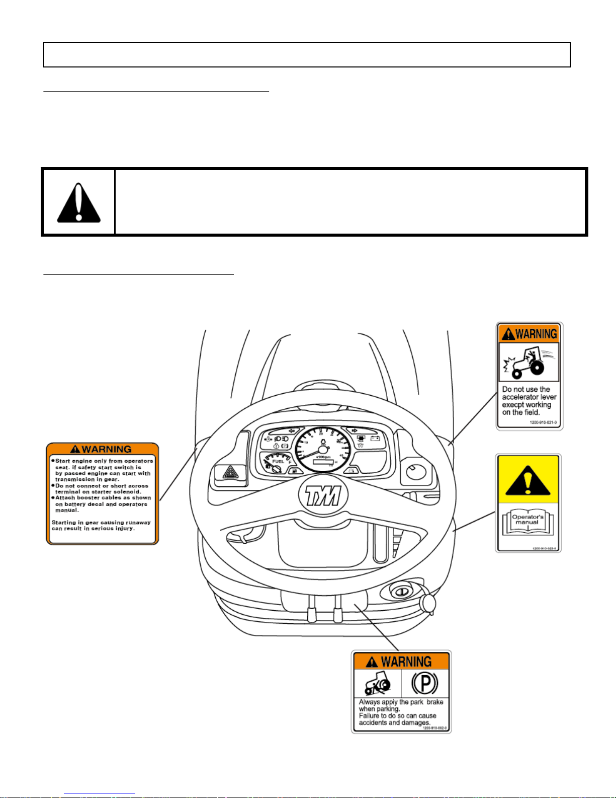
DECALS ON THE DASH COVER
30

DECALS ON THE CHASSIS
31

32
DECALS AROUND THE SEAT

UNIVERSAL SYMBOLS
Some of the univ e rs a l symbols and their meaning are shown be l ow.
Engine Speed
rev /min x 100)
Pressured-
open slowly
Corrosive
Substance
Hours,
recorded
Continuous
Variable
”Tortoise”
Slow or
Minimum Setting
Engine
Coolant
temperature
Warning
”Hare” Fast or
Maximum
Setting
Fuel Level
Hazard
warning
Transmission
oil pressure
Engine
Stop
control
Neutral Turn signal
Lights
Fan
Transmission
oil temperature
Horn
Power take
off engaged
Parki ng br ake
Engine oil
pressure
Power
take off
disengaged
Work lamps
Air filter
Lift arm
raise
Differential
lock
Battery charge
Lift arm
lower
See
operator’s
manual
33

Section - A
Controls,
Instruments
and
Operations
The following pages in this section detail the location and function of various instruments, switches
and controls on your tractor.
Even if you operate other tractors, you should read through this section of the manual and ensure
that you are thoroughly familiar with the location and function of all the features of your new tractor.
Do not start the engine or attempt to drive or operate the tractor until you are fully accustomed to
all the controls.
It is too late to learn once the tractor has started moving.
If in doubt about any aspect of the operation of the tractor, consult your TYM
tractor dealer/distributor.
Particular attention should be paid to the recommendations for running the tractor to ensure that your
tractor will give the long service life and dependable performance for which it was intended.
34

DESCRIPTION OF TRACTOR CONTROLS
► INSTRUMENTS AND SWITCHES
► MAIN SWITCH (KEY SWITCH)
[OFF] - The key can be inserted or removed
[ON] - The electric circuit is on.
[GLOW] - Glow plugs preheat the combustion chamber
[START] - The starter motor is engaged.
When the key is released it will return to the ON position
► HEAD LAMP, TURN SIGNAL SWITCH AND HORN
■ HEAD LAMP SWITCH
High and low beams are operated on the main switch
Position ①: Low beam
Position ②: High beam
■ TURN SIGNAL SWITCH
Pull the turn signal lever down to signal a left turn.
Push the turn signal lever up to signal a right turn.
■ HORN
Push the Red button.
35
Right Turn Signal Lamp
Tachometer
PTO On/Off Button
Hand Throttle Lever
Left Turn Signal Lamp
Fuel Gauge
Hazard Warning
Turn Signal S/W
Horn S/W
Head Lamp S/W
Key S/W
Parking Brake Lever

► TACHOMETER
This meter shows the revolutions of the engine and the
PTO shafts as well as the travel speed in top gear.
► FUEL GAUGE
Shows the amount of fuel in the tank when the ignition
switch is ON.
► HOUR METER
The hour meter consists of digits with the last digit
indicating 1/10
th
of an hour.
► HAZARD WARNING SIGNAL SWITCH
Push the hazard warning signal once to operate the hazard
warning lights. (Left and right turn indicators flash).
Push the hazard warning light switch again to switch off the
hazard warning lights.
36
Hazard Warning Signal S/W
Fuel gauge

►WARNING LIGHTS
CHARGE LAMP
This light will go off as soon as the engine starts to run to indicate that the alternator is
charging. (Please note that a broken fan belt can cause the light to come on.
In this case, stop the engine as overheating can occur if not rectified immediately)
OIL PRESSURE LAMP
Will go off as soon as the engine starts if the oil pressure is correct.
If it comes on while the engine is running, stop the engine and get expert advice.
PTO MONITOR LAMP
Shows the revolution of the PTO.
Refer to Monitor Lamp on page 38.
High Bea m L amp is operated on the com bina t ion switc h.
Low Beam Lamp is operated on t he combination switch.
Glow Signal Lamp indicates preheating.
FUEL LEVEL : If it comes on while the engine is running, fill the tank with fuel.
37
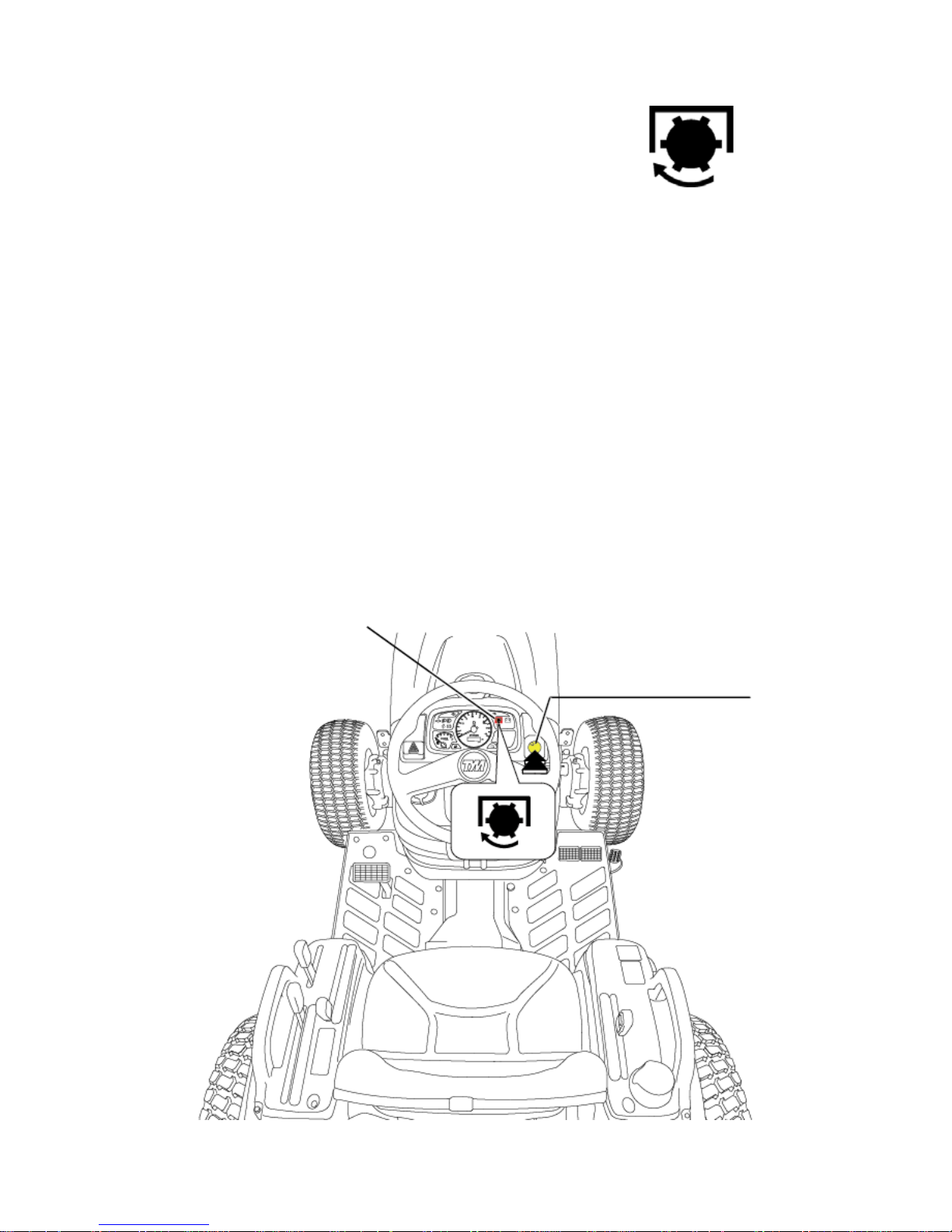
PTO monitor Lamp
■ THE PTO MONITOR LAMP
On the dash panel indicates the state of the PTO shaft.
1. If the monitor glows: The PTO is rotating.
2. If the m onit or i s of f: The PTO is off.
38
The PTO shaft will not rotate if switch is in OFF position.
■ PTO ON/OFF SWITCH
PTO ON/OFF switch is situate d on t he r ight hand side on the i ns tr ument panel and can
be identified easily with its built in yellow colored indicator.
When the switch is pushed dow n to s t a r t the PTO , t he indi c a t or will glow, indicating
that the switch and the PTO are ON.
If the swit c h is pushe d down and turn counte r c l oc k w i se, the indicator will go off ,
signaling that the PTO is OFF.
PTO LAMP
PTO ON/OFF S/W

► TRACTOR CONTROLS
► THROTTLE LEVER (HAND THROTTLE)
Pulling the hand towards the driver increases revolutions.
Pushing it away from the driver decreases revolutions.
39
Throttle Lever
► CLUTCH PEDAL
When the clut c h pe da l is pr e s s e d on m ode l s w it h
mechanical transmissions, drive is disengaged and
the gear range and forward or reverse travel can be selected.
When moving off, smoothly release the pedal to set the tractor moving.
Steering Wheel
Clutch Pedal
4WD Shift Lever
Rear / Mid PTO Lever
Sub Gear Lever
Parking Brake Lever
Brake Pedal
Acceleration Pedal
Main Shift Lever
And Reverse Lever
Position Lever
Clutch Pedal
► PARKING BRAKE LEVER
Push the brak e peda l dow n while
pulling the parking brake up to engage.
Press the park i ng bra k e pedal a nd pus h
the brake pedal to release.
► BRAKE PEDAL
Right and le ft brake pedals a re prov i de d to a s s i s t in turni ng t he tr a c t or in the field.
40
A connecting l a t c h is prov ide d t o c onne c t the r i g ht and l e ft brake pedals for high
Speed of road us e .
In the interest of safety always use it on the road or at high speed as using one side
Only can cause rollovers.
When servicing the tractor ensure that the adjustment on both sides is the same.
Caution
► ACCELERATION PEDAL
This Pedal can override a fixed hand throttle setting
Traveling with the parking brake on will damage the brakes.
Important
Parking Brake Lever
Brake Pedal
Acceleration Pedal

Operate the main shift & reverse lever only while seated on the tractor.
Alway s stop the tractor
Always stop the tractor before getting off.
The gear shift lever must be in NEUTRAL for the engine to start
Caution
Avoid damage! To prevent transmission damage.
1. Depress cl utc h pe da l and s top machine motion complet e ly before shifting
the main shift & reverse lever (Changing direction forward and reverse.)
2. While opera t ing mac hine , alw a ys depress clutch peda l a nd s t op
before changing travel gears .
3. Never rest a f oot on the c lut c h pe da l while the ma c hine is in m oti on.
Important
► MAIN SHIFT & REVERSE LEVER
The Main Shift & Reverse Lever is located on the RHS of the operator.
The Main Shift & Reverse Lever provides three forward speeds: 1,2, and 3,
N (neutral), and one reverse speed, R, Forward speeds may be changed
While the tr a c tor and de pr e s s the c lut c h be fore changing dire c t ion.
MAIN SHIFT & REVERSE LEVER
3
R
1
2
41
MAIN SHIFT & REVERSE
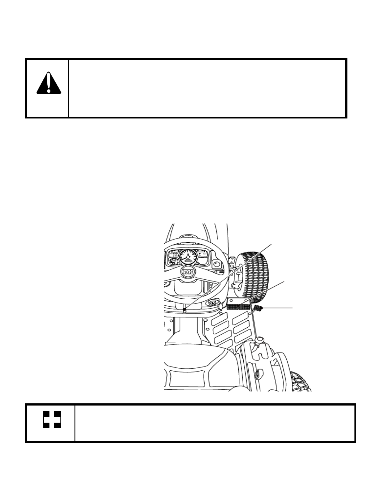
► DIFFRENTIAL LOCK PEDAL
The Differential Lo ck Pedal is located below the
LHS of the Seat.
In case of wheel sli ppage use the diff-lock
by pushing down on the diff lock peda l.
To release it, remove the foot from the pedal.
SUB GEAR LEVER
(RANGE SHIFT LEVER)
► SUB GEAR LEVER (RANGE SHIFT LEVER)
The range shift lever provides two speed ranges L and H.
The tractor should be stopped and clutch depressed before changing speed ranges.
Choose L, M speed range on range shift lever to match work application.
Avoid damage!
Select the proper speed range and gear fo r the mob.
● The machine maybe o perated in any gear with engine speed s at 1 350-3000rpm.
Within the s e limits, the engine can be placed unde r vary ing load opera ti ons .
● Never overload the engine by lugging machine at low idle speeds.
● Raise the engine speed to match expected loads. If a slight increase in engine rpm
occurs
Simultaneously while moving the hand throttle lever forward, the engine is not
overloaded.
Important
42
SUB GEAR LEVER
DIFFERENTIAL LOCK PEDAL

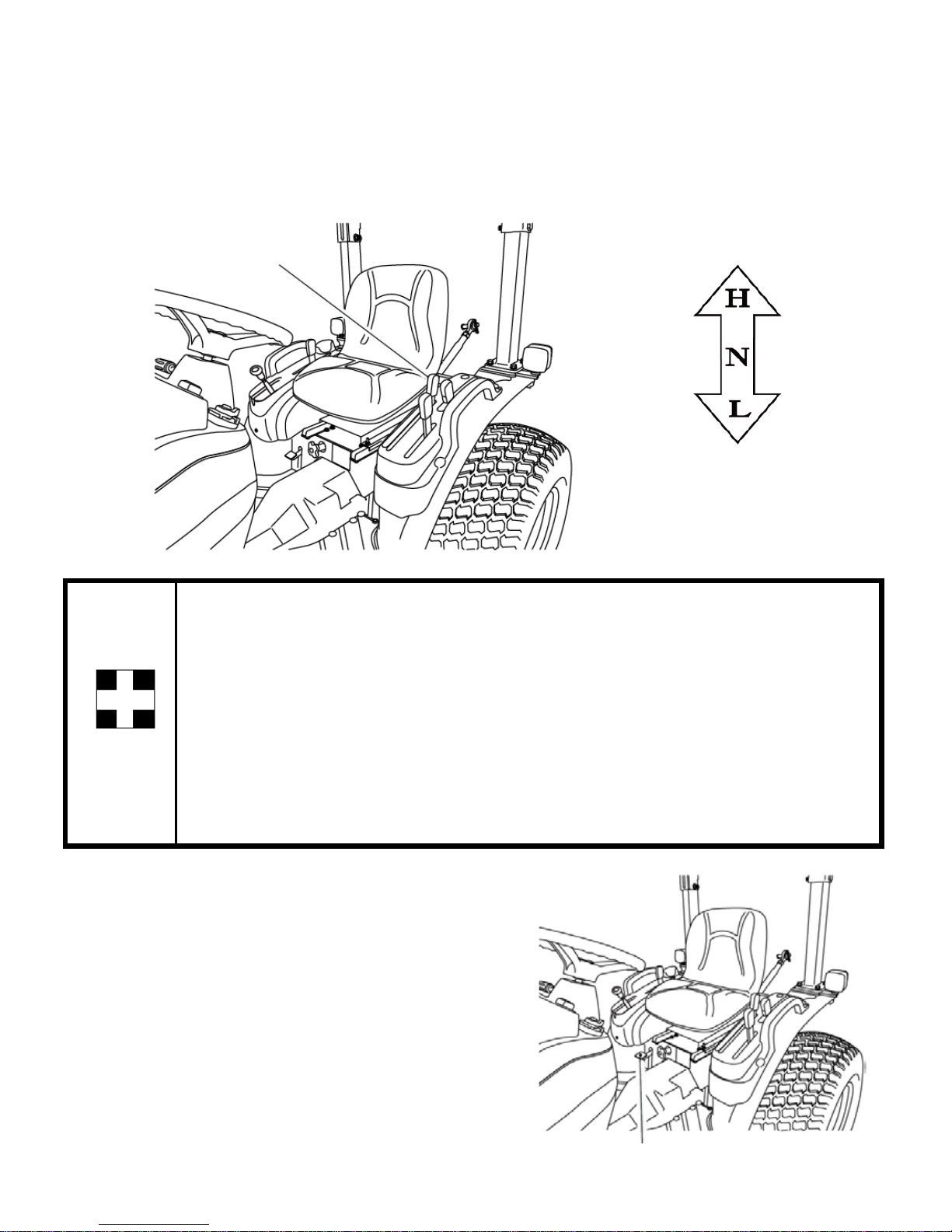
► FRONT WHEEL DRIVE LEVER (4WD)
Front wheel dri ve l ever is located below the
LHS of the Oper a tor .
In the ON position the front wheels are engaged and
in the OFF position they are disengage d.
Engage or disengage the front wheel drive with the
front wheels in the straight position a nd a t low
speed.
Do not use front wheel drive at hig h s pe e d or on the r oa d a s
premature wear of components will result.
The use of front wheel drive improves traction performance.
■ SEAT BELT
-Releasing the Seat Belt
Press button (C) and Pull the Male Fitting (A) from the Buckle (B).
-Adjusting the Se at B el t
Make Sure the be l t i s ac ros s y our hip and not ov e r y our stomach.
To adjust the male fitting (A):
1. Pull the toggle (D) down the strap by the required distance.
a. To make the strap longer, pull the end (E) as far as it can go.
b. To mak e the stra p short e r, pull t he end (F) as far as it can go.
■ OPERATING THE SAFETY SWITCH
If you do not sit on the your seat while operating the tractor,
the engine will turn off.
► DRIVER’S SEAT
To adjust the seat backwards and forwards, lift the lever at
the front of the seat and set it to the desired position (Please refer to page 16 of how to adjust the seat)
Important
43
Front wheel Driver Lever
(4WD Lever)

PTO
REAR PTO
The tractor has one speed PTO (540rpm).
Use the PTO lever to engage.
The PTO switch must be OFF before the PTO is engaged.
1. Decrease the engine speed to near idle.
2. Make sure that the PTO switch is OFF.
3. Engage the rear PTO using the PTO lever.
4. Turn on the PTO s witch.
5. Increase the engine speed to a desired speed.
Both the rea r and mid PTO are provided for variable utility.
They can be engaged simultaneously or independently at same time.
The engine will not start if the PTO switch is in ON position.
The engine will shut off if the operator leaves the seat with parking brake released and the PTO enga ged.
To avoid damage of transm is s ion and i mplement, do not engage the PTO w it h the e ng i ne
running at high spee d.
Caution
44
Engine RPM REAR PTO speed
2893 540RPM
3000 560RPM
Mid
Mid + Rear Rear

MID PTO
The speed of the mid PTO is 2,000rpm. Use the PTO lever to engage.
The PTO switch must be OFF before the PTO is engaged.
1. Decrease the engine speed to near idle.
2. Make sure that the PTO switch is OFF.
3. Engage the mid PTO using the PTO l e v e r .
4. If the rear PTO needs to engage, shift the PTO lever to the correct positi on.
5. Turn on the PTO s witch.
6. Increase the engine speed to a desired speed.
Caution
Do not operate any implement at a high speed than is specified.
When making adjustme nts to the implement, stop the engine to avoid serious
injury.
When leaving the t ractor, stop the engine, remove the key, and set the parking
brake.
Important
If the operator tur ns off the PTO sw it c h, the rea r PTO a nd mid PTO are off at
once.
Mid
Mid + Rear
Rear
45
EG RPM MID PTO Speed
2875 2000 RPM
3000 2087 RPM

► LOWERING THE SPEED CONTROL KNOB FOR THE 3 POINT HITCH
This knob controls the downward speed of the three point linkage of
Hydra uli c and is located below the seat.
After finishing the work, always lower the implement to the ground and switch off
the engine , se t the pa r k i ng brake to avoid injurie s a nd accidents .
► OPERATING THE HYDRAULICS
The hydraulics are powered with an engine driven hydraulic pump and controlled with a position
control le v e r mounted beside the dr iv er.
► HITCH CONTROL LEVER
The hitch cont rol l e v e r is used to raise or lower the impleme nt mounted t o the t hre e point hitch.
To raise the hitch, move the lever to th e r ear.
To lower the hitc h, move the leve r forward.
Adjustable stops are provided for use
whenever it is desirable to return the
hitch control lever to
The sam e operating position.
To slow the downward speed, turn the knob clockwise.
To increase the downward speed, turn the knob counter clock-wise.
To lock, turn the knob clockwise;
Do not over tig hten the knob.
Warning
46
HITCH CONTROL LEVER
RISE
LOWER
Alwa ys set the knob to lock when
1.Trav eling on the road
2. Replaci ng tires or blades on a n impleme nt .
3. Making adj us tments to an implement . The sudden droppi ng of an implement due to
hydraulic problems can cause serious injury or death.
Caution
47
► OPERATING THE 3 POINT LINKAGE (TPL)

► ADJUSTMENT OF THE LIFT ROD
Adjust the le ngth of the lift rod by screwing the Adjus t ing
Handle (T ur nbuc kle) in or adjus t t he leng t h of the lift rod
as necess a r y to set the implem e nt in its work i ng posit ion paralle l to the ground.
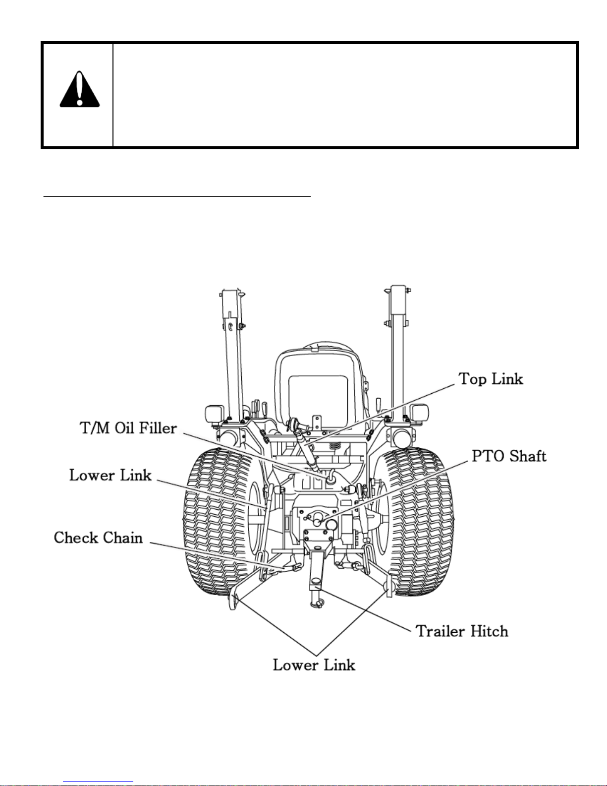
► ADJUSTMENT OF THE CHECK CHAIN
To adjust the c heck chain, turn t he tur nbuc k l e to l e ng t he n or s hort e n the chain.
Tighten the lock nut when the correct adjustment is achieved.
48
Lift Rod
Adjusting Handle
Lower Link
Check chain
Turn buckle
Fixing Nut

Do not attac h a PTO s ha ft with the engine r unning .
Ensure all safety shields are in place.
Only use the drawbar to tow and keep the three point linkage in the raised position
when towing with the drawbar.
Improper position can create unbalance causing the tractor to roll-over & result in the
death or se ri ous injury.
Danger
► M OUNTING IMPLEMENT
If the PTO is used, remove the safety cover from the PTO shaft.
Adjust the yoke rod on the lowe r link s to sui t t he implement
in use. Attach the left lower link, then attach the right lower
link using the a djus t ing handle on t he lev e l ing box if required.
Attach the top link. Attach the PTO shaft to the tractor if used,
making sure that it is locked in place.
Adjust the c he c k chains t o s uit the implement and tighten the
locknuts. To remove an implement, reverse the procedure.
► ADJUSTMENT OF THE YOKE ROD ON THE LOWER LINK
For different applications, change the position of the
Yoke rod on the lower link holes a s shown a nd i ns e r t
the pin in the dir e c ti on of the arrow.
Caution
49
Lift Rod

DRIVING THE TRACTOR
► STARTING THE ENGINE
Before starting the engine carry out the pre-operational che ck s as set out on page 26.
(1) Sit on the driver seat.
(2) Apply the footbrake.
(3) Put the hy dra ul ic lever in the neutra l pos i ti on.
(4) Push down t he clutch to activ a t e the sa fety -starting switch.
(5) Put the main gear lever in neutral.
(6) Insert the ignition ke y and turn it on.
(7) Ensure that the warning lights are work ing.
(8) Alway s turn the ignition key to left for a moment and release it.
The automatic heater will start working, which is indicated by a light on the instrument
panel. As the lamp goes of f, turn the key to the sta r t posit ion to start the engine.
(9) Ensure that all the warning lights are off with the engine running.
Never turn the k e y to the start position while the engine is running a s this ca n
cause serious damage to the starter and engine flywheel.
Only engage the starter for a period of not more than 10 seconds.
If the engine does not s t a rt , r e s t the sta r te r f or about 20 s e c onds a nd tr y again for a
maxi mum of 10 seconds.
f the engine does not start after repeated attempts, refer to the fault tracing guide.
Especially in cold weather, alway s allow the tractor to idle for a while to warm
up and build up suffic ie nt oil pressure.
This will ensure normal operating temperature and offer a longer engine life.
Important
► STOPPING THE ENGINE
-After light work, let the engine idle for a while and turn the key off.
Afte r long or hea v y work allow the engine to idle for 5- 10 minutes and than turn the
key off.
Important
Important
50

► WARMING UP
When starting the engine, allow it to warm up to operating temperature by running it idle for 5-10
minutes to ens ur e ful l lubri c a t ion a nd t ha t the e ngine reache s the oper a t ing tempe r a tur e .
Failure to do s o c a n short e n e ng i ne life substantial ly.
► WARMING UP IN COLD WEATHER
Cold wea the r wil l cha ng e the viscosit y of the oil, resulting i n a reduced oil pum ping ca pa city, whic h
can cause damage to the engine if it is not warmed up correctly.
It also causes problems with the hydraulic system and the synchromesh in the transmission.
Correct times for warming up are:
Temperature Time for warming up
Above 50°F
5~10 min.
50°F~ 32°F
10~20 min.
32°F~14°F
20~30 min.
14°F~-4°F
30~40 min.
Below –4°F
Over 40 min.
Ensure the ha ndbr a k e (foot brake ) is on during t he warm ing period.
Failure to warm up correctly can result in engine problems.
When the eng ine is warm e d up, push dow n the clutch and engage the ma in and aux i li a r y gear levers to
the require d pos it ion.
Push down on the br a k e pedals and rele a s e the handbra k e .
Increas e the eng i ne revolutions a nd l e t out the c l utc h s moothly.
Only change gears with the main gear lever while moving and ensure that this is done with the full use
of the clutch.
► STORING ENGINE IN OPERABLE CONDITIONS FOR 3 MONTHS OR MORE
When the eng ine is not operate d dur ing storag e periods of three m ont hs or more, internal e ng i ne pa r ts
can rust and lose oil film.
As a result, the engine can seize when it is started after st orage.
To prevent such a rust, the engine must be operated periodically during storage.
Important
51

► NORMAL BRAKING AND PARKING
Let the engine come back to idle and at the same time push in the
clutch and bra ke simulta ne ous ly.
When the tractor has come to a halt, lower any implement to the
ground, and put the main gear in neutra l.
Apply the parking brake, stop the engine, and remove the key.
Always apply the parking brake when parking.
Failure to do so can cause accidents and damage.
As an extra precaut ion, chock the rear wheel s when parking on a slope.
Caution
Illustration
► UPHILL STARTS ON A STEEP SLOPE
With the peda ls conne c ted toget he r push dow n on t he br a k e Pedals and push down the c lut c h.
Set all gear levers to low and the throttle to medium engine s peed.
Release the clutch and as it engages release the brake pedals.
Adjust the thr ott le t o the required s pe e d.
When operating in hilly terrain, the risk of rollover increases substantially.
Please drive with extr a care.
When towing trailers in hilly terrain, ensure that they are equipped with brakes.
Use a lower gear to get maximum engine braking and do not change gears on a down
hill run.
Warning
52
► DRIVING DOWNHILL
Use the engine’s ability to brake when traveling downhill.
Never rely on the brakes only and never travel downhill with the gears in neutral.

► FUEL GAUGE
To avoid excessive condensation in the fuel tank, refill it at the end of each
day’s work and ens ure during the day that it does not drop to a low enough leve l
where the fuel system will require bleeding to expel air i n the system after
refilling the tank.
► ENGINE COOLING WATER
If the gaug e indicat e s tha t the e ngine is running hot , stop the tra c t or and
check the coolant in the radiator.
► CHECK DURING DRIVING
Constantly monitor the warning lights on the dash and if any light
comes on, stop the tractor to determine the cause.
If the oil pressure light comes on, first check the oil level.
If the oil level is OK, ask a qualified dealer to check the
reason for the li g ht c oming on.
If the alternator warning light comes on, check all
connections and ensure that the fan belt is not broken.
If all connec ti ons a nd the fan belt are intac t consul t your
dealer to determine the cause of the problem.
When trav e li ng on public or f a rm roads connect both brake pedals a nd a ll ow for the
weight of any mounted im ple ment to ensure that the unit is not unba la nc e d.
Also allow for the width when passing other road users.
Where fitted use the hazard lights provided.
Strictly follow the local traffic regulations.
Caution
When operati ng near others with an impl ement attached take particular care to
allow for the w i dth of the i mplem e nt and avoid a c cidents.
Caution
Also, check to ensure that the fins in the radiator core are not clogged or that the tractor has a
broken or st re t c he d f a n belt .
Allow the engine to cool down before the opening radiator as serious burns may
result due to hot steam & boiling water.
Danger
53

Section-B
Lubrication
&
Maintenance
This section gives the full detail s of the service procedures necessary t o maintain your tracto r at
peak efficiency while the lubrication and maintenance chart provides a ready reference to these
requirements.
54

CHECKS AND SERVICE
► PRE-START CHECKS
To avoid problems it is recommended that a range of checks be carried out daily before starting
the tractor.
For full deta il s of the items and f requency please refer to the tables on pag e 58, 59 and 60.
► ENGINE COOLANT
Remove the radiator cap and ensure that the
coolant is up to the filler neck and that it is
clean with the correct anti-freeze or anti
corrosion inhibitor i n it.
If the coolant i s i n rust y color, drain the
system completely and refill it with the
correct mixture of water and anti-freeze o r
corrosion inhibi tor.
► ENGINE OIL
Pull out the sti c k , w i pe it and dip i t in the oi l s ump. Ensure that the oil le vel is betwe en the upper and
lower marks near the upper mark.
If it’s too low add oil , but ne ver after the 100hrs s e r v i c e interv a l .
Do not overfill the crankcase with oil.
Important
55
Engine Oil Gauge
Engine Oil Filter
Engine Oil Filler

► FUEL
The Fuel Filler is located on the rear of the seat.
Use the fuel gauge t o check the fuel level and top
off if it is too low.
It is a good practice to refill the tank immediately
after use to av oid c onde ns a t ion
► TIRE PRESSURE
The air pressure used in the tires has a direct
bearing on the life of the tire and its
performance in the field.
Ensure that the tire pressures are correct and in
accordance with t he table on page 77.
To make a visual judgment see the drawing on the right.
It is strongly reco mmended that tire pressures are checked with a prop er gauge only &
visual inspec tions a re relied upon.
Excess tire pres s ure can cause accidents!
Danger
► TRANSMISSION OIL
Check the level with level gauge on the rear of the transmissio n.
If the level is low, add oil through the filler hole.
Alwa ys ensure that you use the cor r e c t oil for topping off or oil changes
Caution
Important
56
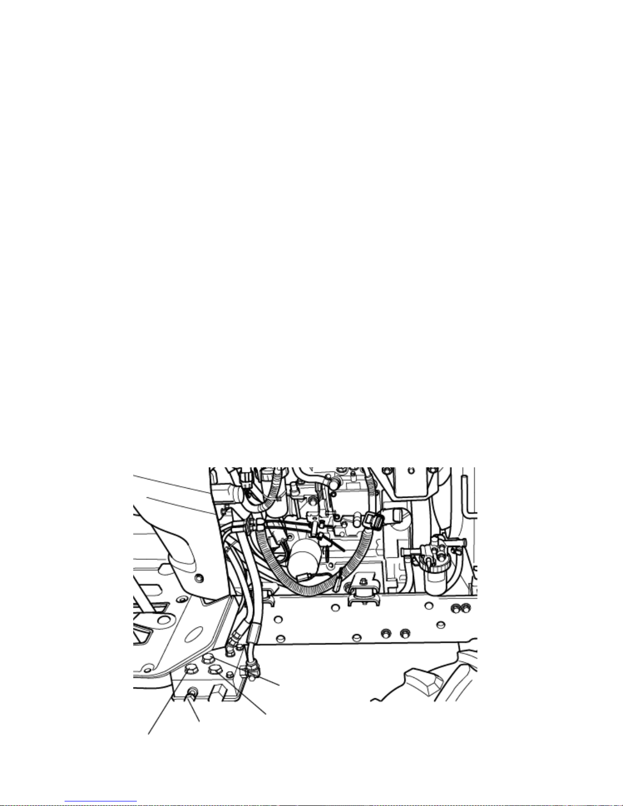
► STEERING
Ensure that the steering wheel does not have excessive free play.
► BRAKE
Ensure that the left and right brak e rods a r e adjuste d c or r e c tl y so that they operate s i multaneously.
The correct free play on the brake is 1.18-1.57 inches (30~40 mm) .
► ELECTRICAL
Check the operation of all gauges, switches, horn, lights and indicators.
► INSTALLING LOADER
1. Connect the P port of the loader control valve to the line on t he tra c t or marked P (from the PTO valve )
2. Connect the T port on t he loa der control v a lve to the line on the tra ctor marked T.
3. Connect the re maining line from the control v a lve to the line on the tra c t or marked P1.
( to the transmission housing)
► DETACHING THE LOADER (LOADER VALVE OR LOADER CONNECTING PORT)
1. Detach the hydraulic hoses of the loader.
2. Asse mble the cap (PF3/8) w it h the pi pe c omp (PF3/8).
57
C
T
Loader select cock
P

MAINTENANCE AND ADJUSTMENT SCHEDULE
► Periodical check and service table
○ Check, Top-off or adjust ● Replace
△ Clean or wash ★ Consult the service Dealer
These intervals are f or operati on unde r nor mal conditions a nd ne e d t o be re v iewed
under severe conditions to a greater frequency
Caution
58
Division
Item
Daily
Service interval(hour meter,mark)
Frequency Comment
5
0
1
0
0
1
5
0
2
0
0
2
5
0
3
0
0
3
5
0
4
0
0
4
5
0
5
0
0
5
5
0
6
0
0
Engine
Engine oil
●
● ● ● ● ●
Every 100 hours or
12 months after
first 50 hours
To correct
level on the
dipstick
Air cleaner
△ △ △ △ △ △
Clean every 10 0
hours
● Replace every 1
year
● Replace the
element after
cleaning it 5 time
or it is damaged
Radiator
coolant
○
Replace every 2
year
See page 66.
Radiator
○
Clean every 2 year
Fuel
○ △ △ △
Everyday and
before work
Fill tank
Fuel filter
○
△
● △ ● △ ●
○ Every 200 hours
△ Every 100 hours
Fan belt
○ ○ ○ ○ ○ ○
Every 100 hours
See page
70.
Battery
○ ○ ○ ○ ○ ○
Every 100 hours
Oil filter
● ● ●
Every 200 hours
Loose nuts
and bolts
○
Check daily Tighten
Radiator
hose clamp
○
Tighten if
required

Division
Item
Daily
Service interval (hour meter/mark)
Frequency Comment
5
0
1
0
0
1
5
0
2
0
0
2
5
0
3
0
0
3
5
0
4
0
0
4
5
0
5
0
0
5
5
0
6
0
0
Chassis
Trans
mission
oil
○ ● ★ ●
Every 500
hours or 12
months after
first 50 hours
Free play
of brake
pedal
○
Check daily
Operation
of each
lever
○
Check daily
Free play
of steering
wheel
○
Check daily
About 50 mm
(1.97 in) on
circumstance
Toe-in
★ ★
Check after
every 300
hours
(0.08~0.24)
Grease in
front
wheel hub
○ ○
Grease every
300 hours
Grease
each
nipple
○ ○ ○ ○ ○ ○ ○ ○ ○ ○ ○ ○
Replenish
every 50
hours
(everyday in
dusty
conditions)
Check the
steering
wheel
joint
○ ○ ○
Adjust every
300 hours
Wheel nut
fastening
torque
○
Check daily
Tighten if
loose
Front : 116130 (ft-lbs)
Rear : 268-28
(ft-lbs)
59

Division
Item
Daily
Service interval(hour meter,mark)
Frequency Comment
5
0
1
0
0
1
5
0
2
0
0
2
5
0
3
0
0
3
5
0
4
0
0
4
5
0
5
0
0
5
5
0
6
0
0
Chassis
Operation of
the
instrument
○
Check
daily
Adjustment
of the
throttle
pedal
○ ○
Free play of
Clutch pedal
○
(0.78~1.18in)
4WD front
axle housing
oil
● ○ ○ ○ ○ ●
Check
after every
100hrs .
Replace
every
500hrs
after first
50hrs
Replace if
leaking
Rubber
pipes
○ ○ ○ ○ ○ ○
Check
after every
100 hours
60
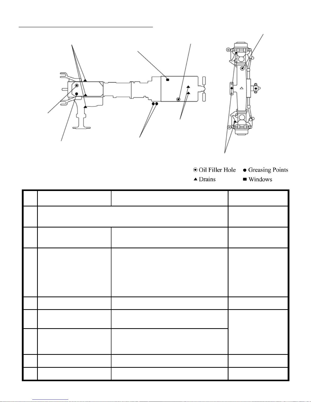
► FILLING DIAGRAM & CAPACITY TABLE
No.
Filling point Fillings Quantity Liter (gal.)
MODEL T254NC
1 RADIATOR
Fresh clean wate r (L .L .C) with an antifreeze,
mixed in ratio o f m inimum 50%
3.8ℓ(1US gal)
2
ENGINE
API : CD/CE grades
Above: 25°C (77°F)…SAE30 o r 10W -30
0°C to 25°C (32°F to 77°F)…SAE20 or
10W30
Belo w 0°C (32°F)…SAE 10W or 10W-30
TYM HEAVY DUTY SAE 15W-40
2.7 ℓ (0.71 US gal)
(MAX)
3 TRANSMISSION CASE See next page *
17ℓ (4.5 US gal)
4 FR O NT AX LE
(API GL-4 Grades) Gear oil #80 or #90
TYM EP GEAR O IL S AE 80W-90
3.5ℓ (0.92US gal)
5
FINAL DRIVE CASE(B) (API GL-4 Grades) Gear oil #80 or #90
TYM UNIVERSAL TRACTOR FLUID
6 BALL JOINT Grease
As required
7 FUEL TANK Diesel fuel
22ℓ (5.81 US gal)
61
Transmission Drain
T/M Oil Gauge
Transmission Filler
Speed Control Pe dal R od
Engine Oil Gauge
Engine Oil Filler
Front Axle Drain
Front Axle Oil Filler/Gauge
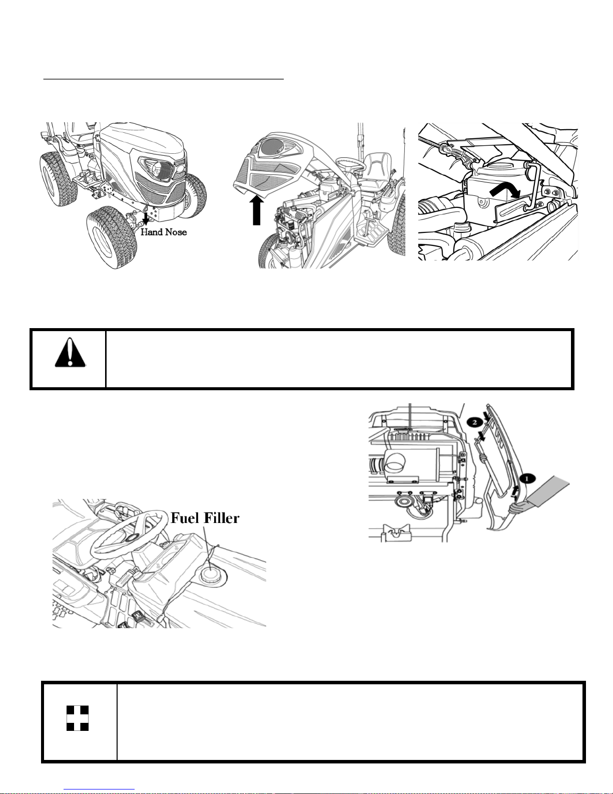
► OPENING METHOD OF EACH COVER
► OPENING METHOD OF FAN COVER
► FUEL
Use clean diesel fuel only .
► RECOMMENDED TRANSMISSION OIL
① TYM UNIVERSAL TRACTOR FLUID
As diesel fuel equipment is susceptible to contamination by
dust or water, ensure that all du st and water is kept well away from the fuel tank.
Important
62
Pull the lower center lever of the front grille counter clockwise, pull the lower edges of hood panel
upward, and pull the whole panel forward until the guide hook lock is hooked to the groove.
▶ Opening the s i de cov e r
To open the side cov e r , gr a b it a nd pul l t he forwar d
panel upwa r d to se pa r a t e from guide the support pin (1).
And pull the side panel forward again,
guide hook lock
Muffler might be “HOT” Always be careful when you hook the lock to the
groove because the hood and latching is close to muffler.
Caution

■ BLEEDING THE FUEL SYSTEM
1. Fuel filter cock 「ON」
2. Open the c oc k on the fuel injec ti on pump
3. Fill the tank with fuel and turn on the ignition key.
4. Start the engine and allow it to run for a while
5. Close the fuel injection pump cock.
6. The bleeding of the system is now finished.
■ CLEANING THE FUEL FILTER
1. Close the fuel cock.
2. Remove the fuel filter element.
3. Wash the fuel filter element in clean di esel fuel.
If necessary, repl ace it.
4. Fit a cleaned or new fuel fil ter element.
5. Open the fuel cock.
6. Bleed the fuel system
Never use petrol, thinners or any other similar flammable material to clean the
fuel filter.
①
Important
63
②
Fuel Filter Element
■ CLEANING OIL WATER SEPARATOR
If any foreign material or water is
seen through the sight glass, remove
it by performing the following steps
1. Prepare a container to collect fuel
from the oil water separator.
2. Open the drain pl ug .
3. After a sufficient amount of fuel
is drained, tighten the drain plug with a hand.
4. Do not use any tool.
Fuel Filter Cock

Always use the same grade and specified oil as replacement.
The drained oi l s houl d be di spos e d of according to local regula t ions .
When changing t he oil, always change t he filter.
Always use th e same oil, as using different oils or specifications can cause damage.
The drained oi l s houl d be di spos e d of according to local regula t ions .
► CHANGING THE TRANSMISSION OIL
1. Allow the transmission oil to cool.
2. Rem ov e the drain pl ug from bottom of the tra ns mission and drain the oil.
3. Replace and check the drain plug.
4. Refill the transmission to the correct level on the dipstick with new oil: Qty 17ℓ (4.5 US gal)
► CHANGING THE OILS IN THE TRACTOR
Always use quality oils for engine or transmission oil.
Refer to the table on pa ge 58 and 59 for the cha ng e f r e que nc y.
► CHANGING ENGINE OIL
Park the tractor on a level surface, shut-off the engine and remove
the sump plug & drai n oil .
Replace and c he c k the sum p plug a nd r e fill the engine w it h oil to
the correct level on the dipst ic k (approx. 0. 71 g a l ) .
The grade of oil to be used will depend on the ambient temperature.
The tractor is shipped from the factory with 15W/40.
For summer use over 77℉ use SAE 30
For tempe r a t ures from 32℉-77℉ use SA E20 or 15W/40.
For tempe r a t ures below 32℉ use SAE 10W.
Important
Important
64
Engine Oil Gauge
Engine Oil Filter
Engine Oil Filler
T/M Drain Plug
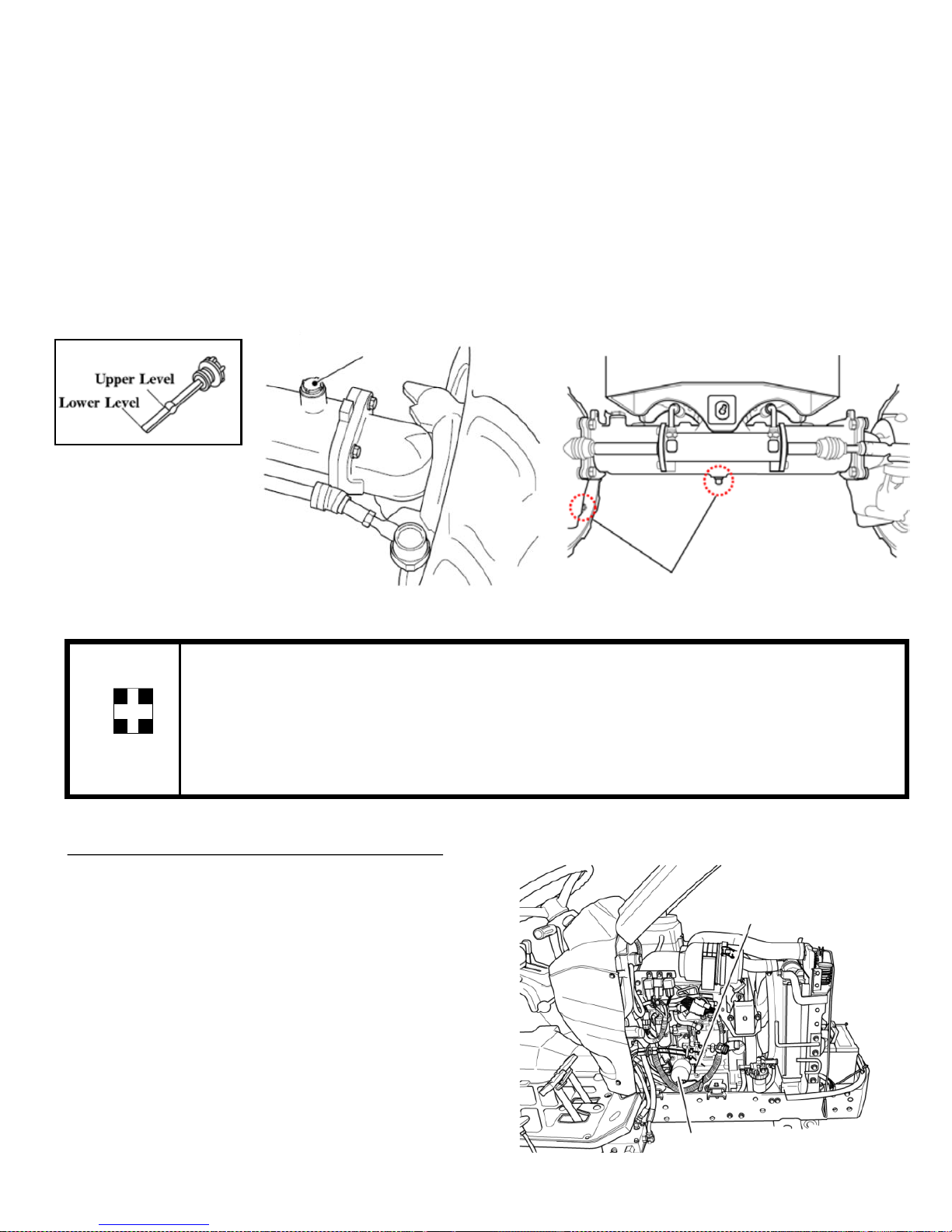
► CLEANING AND CHANGING FILTERS
► ENGINE OIL FILTER
Using a filter wrench turn the filter
counterclockwise to remove it.
Lightly smear the rubber s e a l on the new
filter with oil, turn it clockwise
until the sea l conta c t s the ba s e and t he n tur n it
another 2/3 t ur n to t ighten it.
Some operator s have found tha t when they fill up with the correc t amount of oil ,the
level on the dipstick is too high due to the fact that it takes a while for the
oil to run into the final drives.
Opening the Vent plugs helps to s pe e d this up.
Important
► CHANGING OIL IN THE FRONT AXLE
1. Drain the oi l from the center diff plug and the dra in pl ug i n e a c h driv e .
2. Replac e and t ig ht e n all dr a in pl ug s .
3. Remove the Fill/Lever plugs from each final drive to vent air from it.
4. Remove the dip stick from the filter hole and fill with front axle oil capacity to 3.5ℓ (0.92 US gal)
and allow time for the oil to drain into the final drives.
5. Check the oil level with the dipstick and replace the Fill/Lever plugs on both final drives and tighten
them
65
Fill/Level Plug
Engine Oil Gauge
Engine Oil Filter
Front Ax l e Drain P lug

► CHANGING THE COOLANT
(1) Open to drain cock.
(2) Open the radiator at the same time.
(3) To give a thorough clean, run a hose into the radiator and flush it out.
(4) Close the tap and refill the radiator with a coolant mixture of water and corrosion inhibitor
or anti freeze.
(5) Start the eng i ne and a ll ow it to run for approx 5 minutes, check the wate r level ag ain and top off
if required.
Do not remove the radiator cap on a hot engine.
Allow the engine t o c ool down and then turn t he ca p slowly to ensure that
there is no excessive pressure in the radiator.
Caution
Serious burns can result from the contents of pressurized, hot radiators.
Allow the engine t o c ool down complet e ly before opening the r a dia t or.
Caution
► ENGINE OIL FILTER CARTRIDGE
Remove the filter with a filter wrench.
To replace, apply oil or grease on the seal, fit by
hand until the s e a l contac t s , t he n tur n i t by a 2/3rd turn
further to tighten it; check for leaks.
66
Engine Oil Gauge
Engine Oil Filter

► GREASING THE TRACTOR
Grease the tracto r according to th e service schedule (page 59)
Ensure that grease nipp les are cleaned well before any attempt is made to grease them.
► ANTI FREEZE
Frozen cooling water can damage the engine.
Before replacing the anti freeze solution flush the radiator.
Mix the anti freeze solution i n a c c or da nc e w it h the inst ruc t ions applicabl e to t he br a nd of anti
freeze and the local climate.
Replace the solution in the radiator.
In the case of the loss of solution due to evaporation or overflow, refill it with the original mixture ratio.
Water or air under hi g h pr e s s ure can distort the cooling f i ns on the ra dia t or and
reduce their efficiency.
* Pivot Metal
Important
67

► ADJUSTING THE BRAKES
As is the case with the clutch, use of t he brakes will
change the pedal free play and the b alance between
the right and left pedal.
The correct pedal free play is 1.18~ 1.57 inches
■ Adjusting Me thod
Loosen the loc k nut s to a dj us t t he br a k e .
Turn the turnbuckle counter c l oc k wise to increase the
free play, or turn the turnbuckle clockwise to decrease.
Tighte n the loc knut and conf ir m, to fix the nuts.
Check that the free play is correct and the same on both
pedals to ens ur e ev e n bra k i ng .
► GAP ADJUSTMENT
An uneven adjustment of the left and right pedal will result in one sided braking
when the pedals are connected and can cause serious accidents, especially at high
speeds.
Double check to ensure that free play is the same on both pedals.
Caution
► ADJUSTING THE THROTTLE LEVER
If this level is either loose or difficult to move please consult your dealer for rectification of the problem.
► ADJUSTING TOE-IN
If the toe-in adjustment is incorrect, it can cause the severe shaking of both the steering wheel and the
entire tracto r .
The correct toe in is 0.08~0.24 inches.
We recommend that this adjustment is made by the dealer.
68
► ADJUSTING THE CLUTCH
Using the clutch over a period of time will increase the
Free play. The cor r ect free play of th e pedal is
0.7~1.18in T o adj us t, loos e n t he locknut on the
turnbuckle a nd a djus t .
Check the adjus t ment and tight e n the l oc k nut if the free
play is correct.

► CHECKING THE BATTERY
Check the Ind icator
Green color – Good condition.
Black color – Charging necess ar y.
White color – Replace battery.
Low electrolyte levels can cause prematu re bat tery failur e and corrosi on .
Electrolyte contains acid can cause serious burns.
Any spillag e on the s kin should be w a s he d off with running w ater imme diately .
Caution
► BATTERY MAINTENANCE
Low temperatures will affect the performance of batteries so take particular care of it in winter .
For the long-term storage of the tractor, remove the battery and keep it in a cool dry room.
If it is on the tractor while stored, disconnect the negative terminal.
Batteries will self discharge if left for a period of time without use.
To keep them in good condition, c ha r g e them once a m ont h in s ummer and ever y second month in wint e r .
When replacing the original battery, ensure that the replacement battery is the same size.
Failure to do so can cause problems with the electrical circuit.
► BATTERY CHARGING
-A boost charge is only for emergencies. It will partially charge
the battery at a high rate and in a short time.
-When using a boost-charged battery, it is necessary to recharge
the battery as early as possible.
Failure to do this will shorten the battery’s service life.
Important
69
Indicator condition

Always disco nnect the negative ter min al first when removing the battery an d
always connect the positive terminal first when fitting the battery.
When connecting the battery leads, make sure not to reverse the polarity.
Quick charging will reduce battery life.
Disconnec t t he ter minals prior to charging the bat tery to avoid damage to the
circuit and electrical instruments.
Caution
► FAN BELT ADJUSTMENT
1.Loosen the a l te r na t or pi v ot bolt .
2.Move the a l te r na t or in orde r to i nc r e a s e or
decrease the belt tension.
Tighten the alternator pivot bolt and the link bolt
to 22 N.m (16 lb ft ).
► SERVICING THE AIR CLEANER
■ Cleaning the Air Cleaner Dust Valve
Check that the dust valve is not blocked.
Inspect the rubber flaps for cuts and nicks and check that
the rubber is not pe r i shed.
Replace it if necessary.
To remove dust from the dust valve, squeeze it between
thumb and f i ng e r s .
Wipe around the dust va lve to remove dust, to collect on the
outside..
■ Cleaning/Changing the Element
Release the two clips on the air cleaner end cover
and remove the element.
Remov e dust by blowing compr es sed air through the ele m e nt.
Check the element fo r damage, and if n ecess ar y, change the el ement s .
Check all hoses for condition and tightness.
Never beat the element on a stone or co ncrete floor/wall to clean it.
Check all connections and hoses especially on the clean side of the air clean er to ensure
no dusty air can enter the engine.
Check the element for flaws by putting a light inside the element.
When reassembling, make sure all su rfaces seal correctly to keep dust out.
When working in dusty conditions, increase the service frequency.
► Replace the element after cleaning it 5 times or if it is damaged.
Important
70

Always check the causes for a blo wn fuse; otherwise the new fuse is also likel y t o
blow.
NEVER EVER USE WIRE in place of a correct grade fuse.
► SERVICE PRIOR TO DAILY AND SHORT TERM STORAGE.
Wash the tractor and keep it clean.
Fill the tank to avoid condensa t ion and rust.
Lower any attached implement to the ground before parking the tractor.
For long-term storage, consult your deal er .
Important
71

► CHECKING HOSES AND LINES
The fuel lines , r a diator hoses, hydraulic and rubber hoses a r e consumables, w hi c h dete r ior a t e
by age and use.
Check them regularly and replace them if they are faulty.
Damaged fuel lines leak and cause fires.
Damaged radiator hoses can cause hot water burns, and in severe cases, seize the engine.
Caution
► CHECKING THE WIRING HARNESS AND FUSES
Loose wires make inferior connections and damaged wires can cause short circuits, fires burnt wiring
or reduce the efficiency of the components.
Replace or repa ir a ny faulty wiring or insula ti on.
If a fuse bur ns out again after it has been replaced, do not replace it with wire or a high capacity fuse,
find the cause and rectify it or get an auto electrician to do so.
Where insulation is chafed or peeled off, recover the area with a good quality insulation tape. Where
wiring comes out of its fitting, replace it correctly with the standard fitting.
Incorrec t w i ri ng or fuses can cause fir e s to both the tr a c t or and sur r ounding area so
get the dealer to check it annuall y.
Likewise, fuel pipes and wiring age with use.
Ask your dealer to check them at least once every 2 years an d replace them as
required.
► REPLACING FUSES
The circuit has 8 blade typ e fuses in its wiring circuit
(See diagram on page 86)
When a fuse has blown, replace it with o ne of the same value.
Using a large capacity fuse or wire burns out the wiring system.
Use fuse tongs to replace fuses.
► MAIN FUSES
The wiring harness is equipped with 3 main fuses whose
function is to preserve the wiring.
However when a main fuse blows, the entire circuit becomes dead.
Always check the causes and rectify them before rep lacin g with a
fuse of the same value.
Blown fuses will be discolored.
Important
72
Fuse Case

Long-term storage
When the tractor will not be used for a long time, carry out the same cleaning procedure as for short term
storage.
Drain the oil and replace it with new oil.
Run the engine for approx. 5 min. to ensure that it has new oil throughout the engine.
Drain the coola nt from the radia tor a nd r e move the ignition k e y.
Attach a tag to bo th the key and the steering wheel saying “No coolant”.
Lubricat e all gr e a s e and oil points on t he tra c t or.
Check the pressures and add a small amount of extra pressure.
Lower any implement to the ground or store in a shady dry place.
Disconnec t t he clut c h by using the clutc h di s c onne c ti ng a r m.
Place a piece of wood under each tire to preserve the tire.
After refilling the engine with coolant run the engine for approx. 5-10 m in. at
1500-2000rpm eve ry month as a corrosion preve ntion m e as ure.
Either remove the battery or the negative terminal as mouse damage to wiring can cause
short circuits and fires.
Remove the ignition key and store in a safe place.
Re-use after long term storage.
Carry out a full check of all oils and coolant.
Refit the bat te r y and run the engine at idle for 30 min. to ensure opt imum engine life.
When washing the tractor, ensure that the water does not get near electrical
components or t he oil f i lt e r points.
To prevent short c i r c uit s re move the ignition key.
Do not was h the tra c t or w he n the eng ine i s running .
MAINTENANCE
For daily or short term storage
Clean the tractor and remove all dirt from field work.
Fill the f ue l tank to av oi d c onde ns a ti on a nd r us t.
Lower the im ple ment to the ground.
Keep it in a machinery shed or, if not available, cover the unit if left outside.
In very cold conditions, i t is a dv i sable to remov e the batte r y and keep it inside in a w a r m environment.
This will ensure effective starting when the tractor is required.
When the outside temperature is below 32℉, replace the antifreeze compl etely or drain the coolant to
protect the e ng i ne f rom damage due to the froz e n cool a nt.
Important
Important
73

Specifications
The specifications on the following pages are given for your information and guidance.
For furthe r inf or mation concerning your tra c tor and e quipment, consult your authorized TY M
dealer/distributor.
TYM improves its policy continuously and reserves the right to change prices, specifications or
equipment at any time without notice.
All date given in this book is s ubje c t to produc ti on variations.
Dimens i ons and weights are approxi mate only and the illustrations do not ne c essary show tractors in
standard c ondit ion.
For exact information about any particular tractor, please consult your TYM authorized
dealer/distributor.
Section - C
74

SPECIFICATIONS
Model: T254NC
ENGINE
Four strokes, Indirect injection, water-cooled
Diesel Engine.
Model : 3TNV80F-SDKTF
No. of cylinders : 3
Displacement(cc) : 1,267cc
Bore : 80 mm (3.15 in)
Stroke : 84 mm (3.31 in)
Compression Ratio : 23.1
Horse Power (kW) : 24.2(17.8kW)/ 3,000rpm
(Manufacturing rating)
Rated Speed : 3,000 rpm
High idle rpm : 3,235±50rpm
Low idle rpm : 1,350±50rpm
Fuel injection pump : Indirect
Cylinder sleeve : Dry
Air Cleaner : Dry Filter element, paper
element filtering
Firing order : 1-3-2-1
Exhaust Muffler : Horizontal Round.
Accelerator : Hand Accelerator
ELECTRICAL STARTING AND LIGHTING
Battery Capacity : 12V 50AH
Starter : Solenoid Engaged.
Key Start with Safety ,
starter switch
Alternator : 12V 40A
Instrumentation : Hour meter, Tachometer
Fuel Gauge
Warming Lights
Lighting: : Head lights,
Turn Signal Indicator Lamp,
Brake Lamp, Tail Lamp
Type : Dry single plate
Outer dia. x Inner dia. : 8.86 x 5.9”
TRANSMISSION
Type : Constant mesh, Sliding gear
No. of gears : 6 forward speeds
2 reverse speeds with
high-low selection lever
STEERING
Type : Hydraulic power
(Power steering)
POWER TAKE OFF
Mid mounted : 6 splines
Rear mounted : 6 splines
Diameter : 1⅜ in.
Standard PTO :
Rear - 540 rpm
Mid – 2,000rpm
BRAKES
Foot operate d, independe nt w ith provision of
inter lock for simultaneous operation.
A foot brake is fitted for parking.
Inner dia. : 77 mm
Outer dia. : 123 mm
Number of lining : 4 each side
Total brake thickness : 3.4 mm
HYDRAULIC SYSTEM
3 Point linkage : Category 1(N)
(Adjustable inside check chains)
Control : Position Control
75

► MAIN SPECIFICATIONS
MODEL T254NC
Engine
Maker Yanmar
Model
3TNV80F-SDKTF
Type Water cooled 4 cycle 3 cylinder diesel
Out put (kW/rpm)
T254NC – 17.8kw / 3,000
Number of Cy l i nder 3
Displacement (cc)
1,267cc
Bore and St r oke
80 mm x 84 mm
Compression ratio
23:1
Firing order 1-3-2-1
Injection pump Indirect
Lubricatio n type Forced circulation
Cooling system Water cooled, Forced circulation
Coolant capacity
3.8ℓ(1 US gal)
Air cleaner Dry Dual Element
Muffler Horizontal
Fuel Diesel fuel (Use ultra low)
Fuel Tank capacity 22ℓ (5.81 US gal)
Electrica
l
Battery 12V50AH
Starting system Starter motor with pre-heater
Starter Capacity 1.7KW
Alternator 12V 40A
Drive
Train
Transmission
Mechanical, Sliding Gear, Synchro Mesh
2 range gear
MFWD (4WD) Standard
Differential lock Bevel gears with diff-Lock
Brakes Wet disc brake, mechanical
Steering Hydraulic
76

MODEL T254NC
Clutch
Main Dry single disc, mechanic
PTO Multiple wet disk
Dimensions
(W/R3 Tire)
Overall length(mm) 2350
Overall width (mm) 1290
Overall Height (mm) 2278
Wheel base (mm)
(Distance between shafts)
1460
Min. Ground Clearance (mm) 207
R1
Front 6-12 6PR
Rear 9.5-16 6PR
R3
Front 20X8-10
Rear 29X12.5-15
R4
Front 20X8-10
Rear 27X12.5-15
Axle type
Front Center pin
Rear Central axle
77

Implement
Operation Hydraulic
Mounting method 3-Point hitch
Drawing method Trailer hitch
3-Point hitch category Category 1(N)
Hydraulic-control Position
78
* SPEED CHART (KM/H) (Engine Rated RPM)
R1 R3 R4
L -1 0.98 0.85 0.81
L -2 1.74 1.51 1.44
L -3 3.04 2.65 2.53
H-1 5.33 4.64 4.43
H-2 9.47 8.24 7.86
H-3 16.57 14.42 13.75

FUEL SAVING TIP S
To save fue l and oil in your tractor, the followi ng measure s should always be made .
A) Air Cleaning System
1) Clean the air cleaner regularly so that dust does not settle down.
2) For ever y 50 hours and everyday in sandy:
(a) Clean th e air cl eaner filter element with compressed air.
(b) If the rubber ri ng is cut or expanded, cha ng e it with a new one.
Fix the rubber at the proper location and check for leakages if any.
(c) If air is leaki ng through t he hos e conne c ti on, check and rectify other leakage s , too.
Note: If the air cleaning system is not properly maintained, it will lead to the early wear of piston rings
and sleeves.
This will lead to problems like the loss of engine power, excessive oil and/or consumption fuel
consumption.
B) Engine
1) Put the engine oil on load after the engine is heated and the water temperature gauge indicates
the needle to be in the green zone.
2) If excessive black smoke is visible, th e paper element of the ai r cleaner, fuel inj ection
pump or nozz le s s houl d be che c k e d.
3) Do not run the eng ine w i thout loa d for more than 2 m inut e s .
It is better to stop the engine rather than run it idle.
This will help in save fuel.
C) Brakes.
1) Do not override the clutch or brake pedals.
2) While coming down from a slope, reduce the engine throttle & use low gear.
Do not depend onl y on the brakes f or stoppag e .
D) Fuel system
1) Always use filtered d iesel for the fuel system
2) At the end of the day’s working, it is preferable to fill the diesel tank so that it may prevent
condensation.
3) Change the filter if t he system gets choked.
Do not change both filters at the same time.
If the above recommenda ti ons are not f ol lowed, the fuel inje c ti on pump and injection nozzle will lose
their life early.
Also, it will lead to excessive black smoke and excessive diesel consumption.
79

E) Engine system
1) Always use the recommended grade of oil. (API CD:CE)
2) Every day before starting the engine, check the oil level with a dipstick & refill it so that the level of
oil sits between minimum and maximum levels.
3) Change the engine oil, replace the filter and “O” ring as and when required.
F) Cooling system
1) Check the f a n belt te ns i on r e g ul a rl y and if required.
2) Check the coolant level in the radiator fins and make sure that it is always clean.
3) Replace th e rad iator cap with a genui ne cap, only if required.
4) Do not remove the thermostat, but replace it with a new one if required.
5) Do not change the radiator water often.
Note:
1) Always stop any fuel or oil leakages.
2) Carry out the regular maintenance failure to do so might increase the fuel consumption by 25%.
3) Carry out the torque of cylinder head bolt and adjustment of valve clearance regularly.
Consult your dealer about this issue.
4) Check the tire pressure and inflate the tires as recommended.
5) Always buy genuine spares from the authorized dealer/distributor.
6) Always carry out the service of the tract or by y our authoriz e d dealer /di s tr ibut or .
For any other information, contact y our nea r e s t Author iz ed dealer /di st r ibut or.
80

SYMPTOM CAUSE REMEDY
Engine
Turning the m ain switch
will not operate the starter
Clutch not pus he d in
Battery flat
Switch faulty
Push the clutc h i n
Charge or replace the
battery
Dealer to repair or replace
Contact dealer to repair or
replace
Starter oper a te s but not
enough to turn the engine
Low battery
Bad earth
Thick oil
Charge the battery
Clean the earth lead and
tighten it
Drain and replace it with
correct oil
Starter operates OK but
does not star t the e ng i ne
Air in fuel system
Clogged fuel filter
No fuel being s uppli e d
Glow plug dis c onne c t e d or
not worki ng
Bleed the system
Clean or replace b oth filters
Fill tank or turn tap on
Contact dealer for repair.
Engine rev olutions are
irregular
Air in the fuel system
Faulty injector
Fuel pipe leak
Bleed the system
Contact dealer for repair.
The engine stops at low
revolution
Poor fuel injection
Faulty injection pump
Wrong valve clearance
Wrong idle setting
Faulty injector
Contact dealer for repair
Contact dealer for repair
Contact dealer for repair
Contact dealer for repair
Contact dealer for repair
The engine stops suddenly Lack of fuel
Faulty injectors
Seized engine due to lack
of oil, the w r ong oil or la c k
of coolant
Fill the tank and bleed the
fuel system
Contact dealer for repair
The engine overheats Lack of coolant
Broken or misadjusted fan
belt
Clogged air filter el ement
Clogged radiator
Low oil
Refill with coolant
Adjust or re pla c e
Clean or replace air fil ter
Clean the core
Replace the oil to correct
grade
FAULT TRACKING
81

SYMPTOM CAUSE REMEDY
Engine
White smoke from the
exhaust
Oil level too high
Shortage of or faulty fuel
Reduce to correct quantity
Contact dealer for repair
Reduced performance of
the engine
The injectors are clogged,
carbon coat e d a nd sti c k i ng
Low compression
Leaking valve seat
Incorrect valve gap
Faulty timing
Fuel shortage
Clogged air clean er
Contact dealer for repair
Contact dealer for repair
Contact dealer for repair
Contact dealer for repair
Contact dealer for repair
Fill the tank and check fuel
quality
Clean the element
Oil warning light comes on
with the engine running
Low oil level
Wrong oil
Faulty light or switch
Clogged oil filter
Fill to correct level
Change to correct oil
Replace faulty part
Contact dealer for repair
Alternator light comes on
with the engine running
Wiring fault
Faulty alternator
Low water level or faulty
battery
Broken or loose fan belt
Contact dealer for repair
Contact dealer for repair
Top off or repla c e
Replace or adj ust
82

SYMPTOM CAUSE REMEDY
Clutch
The clutch slips Incorrect adjustment Adjust to correct free pl ay
Worn or burnt lining Contact dealer for repair
The clutch does not
disengage
Incorrect adjustment
Rusty clutch lining
Adjust to correct free play
Contact dealer for repair
Brake
Brake not work ing Incorrect free play
Worn or burnt lining
left and right gap
differences
Adjust to correct free play
Contact dealer for repair
Equalize the gaps
Brake pedal not returning Faulty return spring Lack
of grease on the joints
Replace sprin g
Remove rust and lubricate
with grease
Hydraulic
system
Hydraulics are not lifting Engi ne rev s. too low
Lack of transmission
Oil
Air leaking in from a pipe
Clogged suction filter
Faulty pump
Faulty hydraulic valve
Faulty cylinder
Increase engine revs.
Top off the oil to t he corr e c t
level
Repair or replace pipe or
replace O ring on joint and
tighten
Clean and change oil
Contact dealer for repair
Contact dealer for repair
Contact dealer for repair
Oil leak from pipe Loose pipe joint Cra ck ed
pipe
Tighten joint
Replace or repair pipe
When lifting the relief
valve whistles
The stopper has slipped
down
Adjust the s toppe r
For any other hydraulic problems, please consult your dealer who has the correct equipment to
diagnose and repair the system
83

SYMPTOM CAUSE REMEDY
Steering
wheel
Steering wheel s haking Wrong toe-in
Unequal tir e pres s ur e
Loose component
Adjust toe-in
Inflate both to correct press ure
Tighten or replace if worn
Excessive play in the
steering
Worn steering shaft
Worn components
Contact dealer for repair
Contact dealer for repair
Electric instruments
Flat battery Faulty wiring
Faulty alternator
Faulty regulator
Broken or loose fan belt
Repair, reconnect or tighten as
needed
Contact dealer for repair
Contact dealer for repair
Replace or adj ust
Before performing anything oth er procedures, check the electrolyte l evel of the battery first
and
the connections. Top off if required and clean and retighten the terminal.
Dim head lights Low battery
Faulty wiring
Charge or replace
Repair or replace as needed
Headlig hts not wor king Blown bulb
Blown fuse
Faulty contact
Replace bulb
Replace fuse
Repair or replace and check the
earth
Horn not worki ng Faulty horn butt on
Faulty wiring
Faulty horn
Replace butt on
Repair or replace
Replace
Indicator not w ork ing Blown bulb
Faulty flasher unit
Faulty wiring
Replace bulb
Replace unit
Repair or replace
84

HARNESS DIAGRAM
85

► Drawing for fixi ng posi t ion of the fus e
► Wiring diagram of the electric instrument
* Main Fuse
1
HAZARD 5A
2
COUPLER 15A
3
EG STOP, PTO 7.5A
4
GLOW TIMER 5A
5
LIGHT, HORN 15A
6
PANEL 5A
7
TURN SIGNAL 5A
8
WORKING LIGHT 7.5A
9
STOP LAMP , CRUISE 7.5A
10
11
12
13
86
①
Head Lamp
12V/ 55W
②
Combination Lamp
12V/ 21W/ 5W
③
Stop Lamp
12V/ 21W/ 5W

DATE
JOB CARD
NO.
NATURE OF
DEFECT
PARTS REPLACEMENT
W/CLAIM NO.
AND DATE
REMARKS
TRACTOR HISTORY CARD
87

DATE TRACTOR HOURS NATURE/TYPE OF REPAIR/SERVICE CARRIED OUT
SERVICE RECORD
88

DATE
JOB
DONE
MACHINE HOURS
FUEL
CONSUMPTION
ENGINE OIL
TOPPED UP
REMARKS
START END
DAILY OPERATION LOG
89

PART REPLACEMENT RECORD
DATE
PART
DESCRIPTION
Q’TY COST DATE
PART
DESCRIPTION
Q’TY COST
90

T254NC
Operator’s Manual for TYM Tractors
Code No.
1113-912-002-0
Printed in June 2014
1st Edition
 Loading...