

Page 1

TYM
OPERATOR’S MANUAL
FOR
TRACTORS
ET350 ECONO
#604-9, Namsan-dong, Changwon-city, Kyungnam, Korea ■TEL:82-55-279-4379, FAX:82-55-279-4447 ■www.tym.co.kr
Page 2

JIANGDONG
Off-Road compression-Ignition Engine
Emission Control System Warranty statement
EMISSION RELATED SYSTEM DEFECT WARRANTY
The warranty period shall begin on the engine or equipment purchaser of certified fuel.
JIANGDING Group.co. warrants to the ultimate purchaser and each subsequent purchaser of certified
off-road compression-ignition engine (powering off-road machines and equipment), that such engine is;
1) Designed, built, and equipped so as to confirm with all applicable regulations adopted by the
Environmental Protection Agency.
2) Free from defects in materials and workmanship which cause the failure of a warranted part to be
identical in all material respects to the part as described in the engine manufacturer’s application for
certification for period of five years for 3000 hours of operation, whichever occurs first, for all engines
rated at 19kw and greater, except as noted below, in the absence of a device to measure hours of use, the
engine shall be warranted for a period of five years. For all engines rated less than 19kw, and for constant
speed engine rated under 37kw with rated speeds higher than or equal to 3000 rpm, the period of two
years or 1500 hours of operation, whichever occurs first, shall apply, in the absence of a device to
measure hours of use, the engine shall be warranted for a period of two years.
If a warranted part fails because of a defect during the terms of this warranty, JIANGDONG will repair or
replace it at any authorized JIANGDONG dealer. Any other parts damaged by the failure of a warranted
part will also be repaired or replaced. The repair and/or replacement will be made at no charge to the
owner for parts, labor and diagnosis. Any such part repaired or replaced under the warranty shall be
warranted for the remaining warranty periods.
In case of emergency, repairs may be performed at any service establishment, or by the owner, using any
replacement part.
JIANGDONG Group.co.will reimburse the owner for their expenses, including diagnostic charges for
such emergency repair. These expenses shall not exceed JIANGDONG Group.co. suggested retail price
for all warranted parts replaced, and labor charges based on JIANGDONG Group.co.recommended time
allowance for the warranty repair and geographically appropriate hourly labor rate.
A part not available within 30 days or a repair not being complete within 30 days constitute an emergency.
As a condition of reimbursement, replaced parts and receipt invoices must be presented at a place of
business of an authorized JIAGDONG engine dealer or other establishment and authorized by
JIANGDONG Group.co.
This warranty covers the following emission-related parts and components.
-Fuel Injection pump
-Nozzle Assembly
-Injection pipe
-Turbocharger (if equipped)
-Intake, Exhaust manifold
If failure of these components results in failure of another part, both will be covered by this warranty. Any
replacement part may be used for maintenance or repairs. The owner should ensure that such parts are
equivalent in design and durability to JIANGDONG genuine parts.
Use of non-genuine JIANGDONG parts does not invalidate the warranty. However JIANGDONG
Group.co. is not liable for parts, which are not genuine JIANGDONG parts.
Page 3

RESPONSIBILITY AND LIMITATIONS.
These warranties are subject to the following:
JAINGDING Group.co.RESPONSIBILITIES.
During the emission warranty period, if a defect in material or workmanship of a warranted parts or
component is found. JIANGDONG Group.co.will provide;
-New, remanufactured, or repaired parts and-or components required to correct the defect.
Items replaced under this warranty become the property of JIANGDONG Group.co.
-Labor, during normal working hours, required to make the warranty repair.
This includes diagnosis and labor to remove and install the engine, if necessary.
Owner’s Warranty Responsibilities.
As the JIANGDING Group.co. off-road compression-ignition owner, you are responsible for the
performance of the required maintenance listed in your Owner’s Manual. JIANGDONG Group.co.
cannot deny warranty solely for the lack of required maintenance was the reason for the repair, then
the claim will be denied.
You are responsible for presenting your JIANDONG engine to a DIANGDONG Group.co.dealer as soon
as a problem exists. The warranty repairs should be completed in a reasonable amount of time, not to
exceed 30 days.
As the JIAMGDONG engine owner, you should also be aware that JIANGDONG Group.co.may deny you
warranty coverage if your JIANGDONG engine or parts has failed due to abuse, neglect, improper
maintenance or unapproved, modifications. If you have any questions regarding your warranty rights and
responsibilities, you should contact JIANGDONG Group.co.
Division at 1801 Quality Drive
LIMITATION
The emission control system defects warranty and the emission control system performance warranty shall
not apply to: - malfunctions in any part directly caused by abuse, misuse, modification, improper
adjustment except those done by a dealership during warranty service work, alterations, tempering
connections, improper or inadequate maintenance, neglect or use of leaded diesel or other fuels not
recommended in the owner’s Manual.
-Damage resulting from accident or an Act of God.
-Failure that are a direct result of a lack of performance of required emission control maintenance as
outlined in your Owner’ Manual.
-Parts or accessories used in applications for which they were not designed or not approved for use on the
engine by JIANGDONG Group.co.
-Parts not supplied by JIANGDONG Group.co.or damage to other parts caused directly by
non-JIANGDONG Parts or non-equivalent parts.
-The charge for diagnostic labor which does not lead to the determination that a warrantable condition
exists.
-JIANGDONG Group.co.is not responsible on which or consequential damages such as downtime or loss-
use of engine powered equipment.
-Although you purchase the equipment on which JIANGDONG engine is mounted, if the equipment is not
manufactured by JIANGDONG, you will make contact with purchasing dealer.
Page 4

EMERGENCY SERVICE
If emergency Emission Control System Warranty service is required and the owner is unable to readily
locate an authorized JIANGDONG dealer or if a warranted part is available within 30 days, then, repairs
may be performed at any available service establishment, or by the owner, using any replacement part.
JIANGDONG will reimburse the owner for the owner’s expenses including diagnostic charges for such
emergency repair or replacement at JIANGDONG ’s suggested retail price for all warranted parts
replaced and labor charges based on JIANGDONG ‘s recommended time allowance for the warranty
repair and the geographically appropriate hourly labor rate. Replaced part and copies of paid original
receipts must be available for presentation to JIANGDONG as a condition of reimbursement for these
emergency repairs.
In addition, the owner must provide JIANGDONG a detailed description indicating why the situation
was considered an emergency and why an authorized JIANGDONG dealer was not being complete
within 30 days constitutes an emergency.
Page 5

FOREWARD
Thank you for purchasing our ET 350 ECONO tractor. ET 350 ECONO tractor is characterized by its
compact construction, and big excess power. With relevant implement, it can make various kind or work,
such as plowing, Rototilling, harrowing, seeding, harvesting, irrigation, electric generation,
transportation and gardening, etc…
The correct usage, adjustment and maintenance of the tractor may prolong their service life, and give
their full play. This book, for this reason, is complied to provide the above information for owners of the
tractor.The user of the tractor is required to read this book carefully before putting the tractor into
operation, and strictly to observe the regulations and instructions in using and servicing the tractors.
This Operation Manual excludes the information for engine chapter, which you can find on the separate
Engine Operation Manual attached with.
With the requirements of customers and the developments of engineering science, this product will be
improved continuously. So please notice the contents of the book may be somewhat not accordance with
the tractor you have owned. We will publish new one periodically.
Page 6

CONTENTS
CHEPTER 1 Main Specifications of Tractor …………………………………………………..
CHAPTER 2 Safety Regulations and Important Instructions..……………………………….
2.1 Safety Instructions …………………………………………………………………………
2.2 Safety Regulations …………………………………………………………………………
2.3 Important Instructions. ……………………………………………………………………..
2.4 ROPS (Roll Over Protection Structure) …………………………………………………..
2.5 Safety signs…………………………………………………………………………………
CHAPTER 3 Oiling and Running – in process ….………………………………………………
3.1 Oiling and Fueling of the Tractor ……………………………………………………………
3.2 Running – In of a New Tractor ………………………………………………………………
3.3 Work on the Tractor after Running – in ……………………………………………………...
CHAPTER 4 Operation of Tractor ……………………………………………………………….
4.1 Controls and Instruments …………………………………………………………………….
4.2 Operating and Driving ………………………………………………………………………..
1
4
4
9
9
10
13
17
17
18
19
20
20
24
4.3 Operation of Working Facilities ……………………………………………………………...
4.4 Operation of Electrical Equipment …………………………………………………………...
CHAPTER 5 Important Adjustments …………….………………………………………………
5.1 Important Adjustments Date of Engine ……………………………………………………….
5.2 The Components of Clutch ……………………………………………………………………
5.3 Adjustments of Transmission …………………………………………………………………
5.4 Adjustments of Brakes ………………………………………………………………………..
5.5 Adjustments of Final Drive ……………………………………………………………………
5.6 Fully Hydraulic steering system……………………………………………………………….
5.7 Lifter Hydraulic Tube system …………………………………………………………………
5.8 Adjustment of Tread …………………………………………………………………………..
5.9 Adjustment of Lifter …………………………………………………………………………..
5.10 The Operation Controls of Front Drive Axle …………………………………………………
5.11 The Structure and Adjustment of Front Drive Axle…………………………………………
26
27
30
30
30
35
37
37
38
40
41
42
43
44
5.12 The Structure, Installation and Disassembly of Transmission Shaft and Transfer Case……
47
Page 7

5.13 Connection and adjustment of Front Axle and Its Bracket ……………………………….
47
5.14 Adjusting of Front Wheel Deflection Angle and Toe – in ……………………………….
5.15 Lubricating Points of Front Drive System and Steering System …………………………
CHAPTER 6 Technical Maintenance of Tractor..……………………………………………...
6.1 Technical Maintenance per Shift …………………………………………………………..
6.2 1st Technical Maintenance …………………………………………………………………
6.3 2nd Technical Maintenance ………………………………...………………………………
6.4 3rd Technical Maintenance ………………………………………………………………...
6.5 Special Maintenance of Winter ……………………………………………………………..
CHAPTER 7 Trouble Shooting …………………………………………………………………..
7.1 Engine ……………………………………………………………………………………….
7.2 Chassis ………………………………………………………………………………………
7.3 Electrical System ……………………………………………………………………………
CHAPTER 8 APPENDICES …………………………………………………………..…………..
8.1 Tightening Torque of important Bolts and Nuts …………………………………………….
48
49
50
50
50
51
51
52
53
53
53
56
59
59
8.2 Diagram of Transmission System …………………………………………………………...
8.3 Electrical system wiring Diagram …………………………………………………………...
8.4 Fuel System Diagram ……………………………………………………………………..…
8.5 Hitch System Dimensions ………………………………………………………………..….
60
62
64
64
Page 8
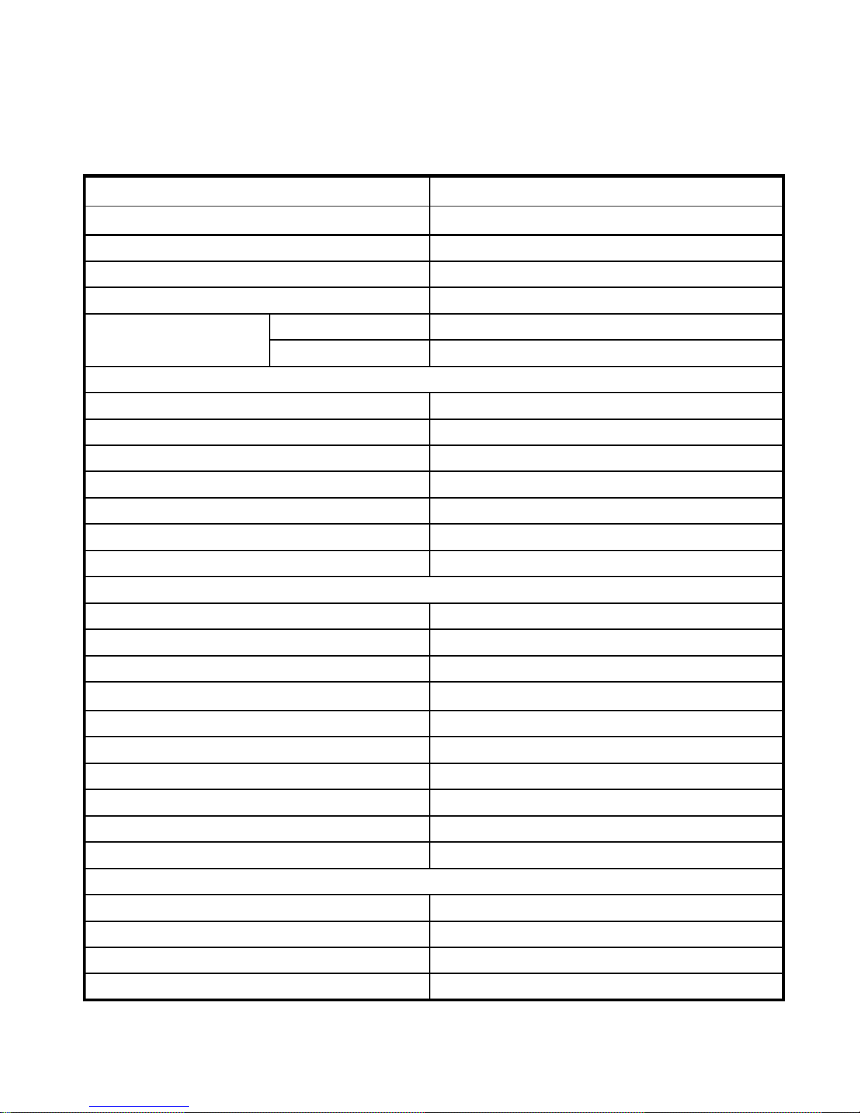
CHAPTER 1. MAIN SPECIFICATIONS OF TRACTOR
General specifications
Tractor Model ET 350 ECONO
Type Frameless, 4WD tractor
Rated draft(kn/kgf) 9.14/932
Dry weight(kg 1450
Min. operation weight(kg) 1565
Front wheel 1160
Wheel tread(mm)
Radius of turning circle(m)
With one side braked 3.4
Without braking 3.8
Min,ground clearance(mm) 290
Overall dimensions(mm)
Length 3070
Rear wheel 1100~1400
Width 1493
Height(to the top of steering wheel) 1540
Theoretical travel speed of tractor(km/h)
1st gear 1.74
2nd gear 2.20
3rd gear 3.58
4th gear 5.68
5th gear 6.83
6th gear 8.63
7th gear 14.04
8th gear 22.27
1st rev. Gear 1.63
2nd rev.Gear 6.38
Engine
Model TY395E
Type Vertical,in-line,water-cooled,four-stroke
Number of cylinders 3
Bore X Stroke(mm) 95/105
1
Page 9
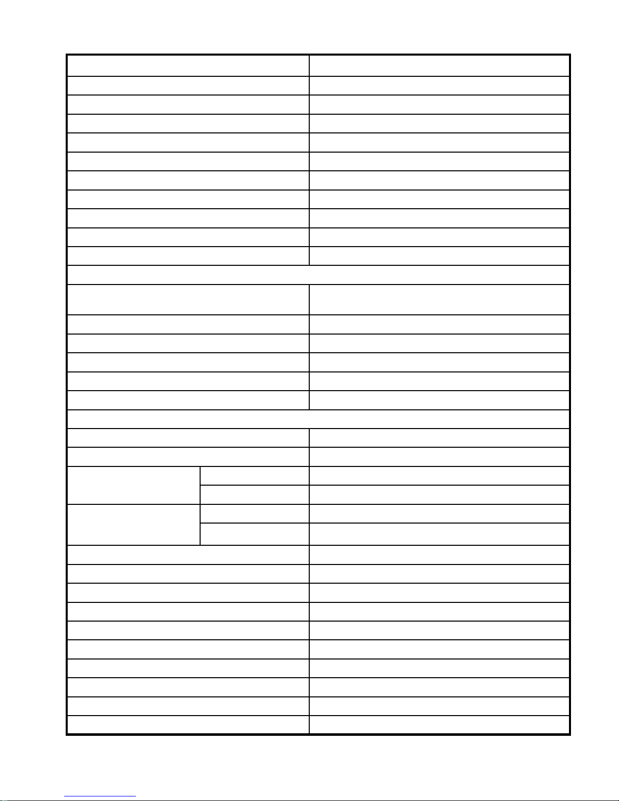
Tractor Model ET 350 ECONO
Rated speed(r/min) 230
Rated output(kW/hp) 25.7/35
Max.torque(Nm)
Speed at max. torque(r/min)
≥122.7
≤ 1725
Fuel consumption(g/kWh) 245
Oil consumption(g/kWh)
≤ 2.04
Method of lubrication Pressure and splash combined
Method of cooling Closed and forced water circulation
Method of starting Electric starting
Rotating direction(as viewed from the fan) Clockwise
Transmission system
Clutch Dry single-disk constant engagement or
Double Belleville spring interlock controlled
Gear box Straight gear (4+1) X 2
Central drive Spiral bevel gear
Differential Two bevel planetary-gear, closed type
Final drive External exterior engagement, straight gear type
Brake Pedal, mechanical-actuated, closed shoe-type
Running and steering system
Type of drive Rear-wheel drive
Type of front axle Tube with adjustable wheel tread
Front wheel 6.50-16
Specification of tire
Rear wheel 11.2-24
Front wheel 0.23~0.25
Tire pressure(MPa)
Rear wheel 0.10~0.12
Toe-in (mm) 3~11
Camber, front wheel
Kingpin inclination
2°
10°
Kingpin caster 0
Steering gear Worm and roller or BZZ1-80 fully-hydraulic
Ackerman steering Backward of axle
Working facilities
Hydraulic lift
Type Partial separated units
Working depth control Draft and position control combined
2
Page 10
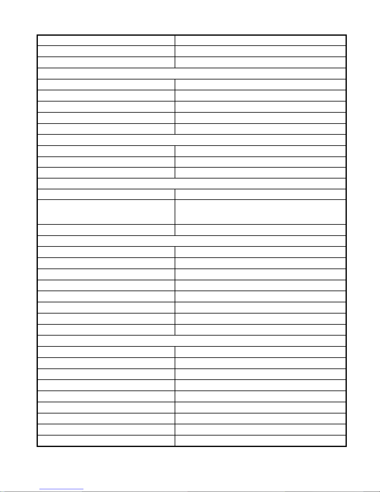
Tractor Model ET 350 ECONO
Oil pump type CBN316L
Opening pressure of relief Valve(MPa) 13.7
Hydraulic cylinder
Type Horizontal, single-action piston type
Bore(mm) 85
Stroke(mm) 110
Distributor Sliding valve control type
Rated lift capacity(at hitch shaft)(kN) 8.33
Suspension linkage
Type Rear-mounted, three - point ball joint, category I
Upper hitch pin diameter(mm)
Lower hitch pin diameter
φ 19
φ 22.4
+0.51
+0.30
+0.33
+0
Power take-off shaft
Type Non-independent or semi-independent
Dimensions of spline
8-spline-38 X 29 X 6 or
+0.032
+0.100
0
-0.28
-0.04
-0.01
6-spline-34.79±0.06 X 28.91 ± 0.05 X 8.69
PTO Speed(r/min) 540,1000
-0.040
-0.098
Electrical system
Type 12V, Negative-grounded, single-line system
Alternator JF11(14V,350W) or FWB 15C31
Regulator FT-70 or FT-111
Starting motor QD146
Battery 6-QA-90
Head light 12V upper beam 45W. Lower beam 40W
Tail light 12V 32CP
Multi - indicating panel
Filling capacities(ℓ)
Fuel tank 40
Engine cooling system 7~9
Engine oil sump 4.5
Fuel injection pump 0.3
Hydraulic oil tank 5.7
Chassis 20.8
Hydraulic lift 7
Front drive axle 6
Intermediate Housing 3.5
3
Page 11
CHAPTER 2. SAFETY REGULATIONS AND
IMPORTANT INSTRUCTIONS
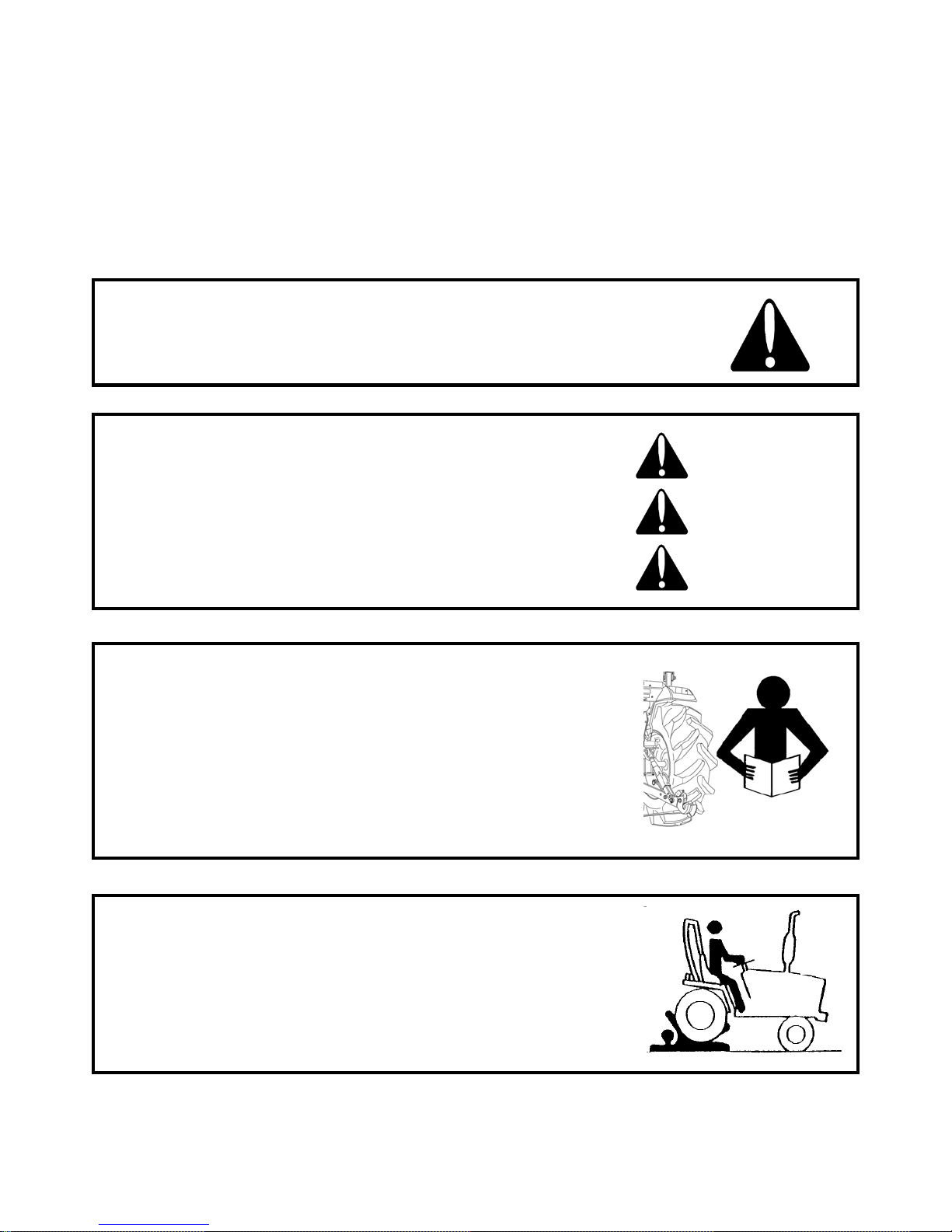
2.1 SAFETY INSTRUCTIONS
RECOGNIZE SAFETY INFORMATION
This symbol means ATTENTION! YOUR SAFETY IS
INVOLVED. The message that follows the symbol contains
important information about safety. Carefully read the message
SIGNAL WORDS.
A signal word―DANGER, WARNING OR CAUTION―is used
with safety alert symbol. DANGER identifies the most serious
hazards. Safety signs with signal Word ―DANGER OR
WA R N I NG ―are typically near specific hazards. General
precautions are listed on CAUTION safety signs.
READ SAFETY INSTRUCTION
Carefully read all safety instructions given in this manual for
your safety. Tempering with any of the safety devices can cause
serious injuries or death. Keep all safety signs in good condition.
Replace missing or damaged safety signs.
Keep your tractor in proper condition and do not allow any
unauthorized modifications to be carried out on the Tractor,
which may impair the function/safety and affect Tractor life.
DANGER
WARNING
CAUTION
PROTECTION CHILDREN
Keep children and others away from the Tractor while operating.
BEFORE YOU REVERSE
- Look behind Tractor for children.
- Do not let children to ride on Tractor or any implement.
4
Page 12
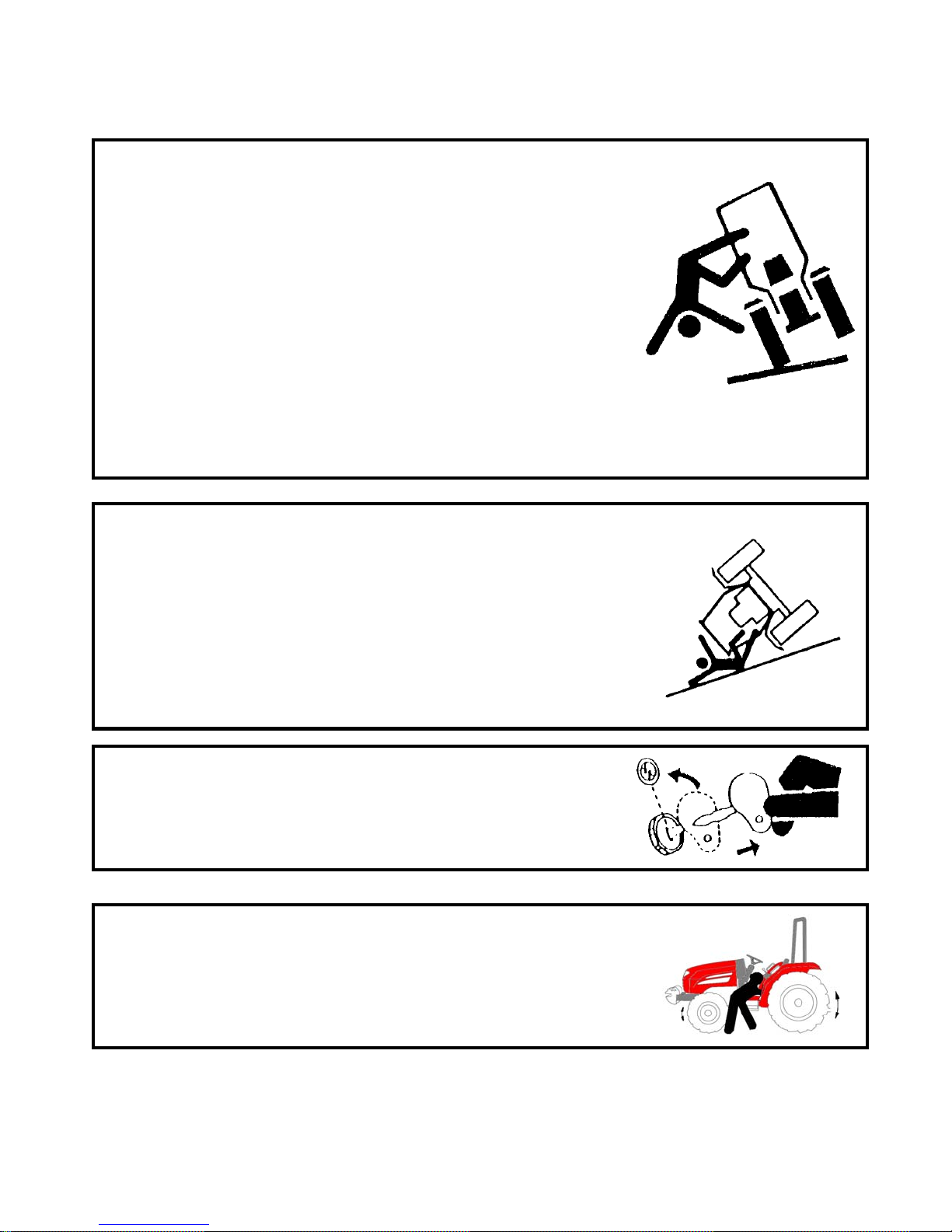
USE OF ROPS AND SEAT BELT
The Roll Over Protective Structure(ROPS) has been certified to
industry and/or government standards. Any damage or alternation to
the ROPS, mounting hard-ware, or seat belt voids the certification
and will reduce or eliminate protection for the operator in the event
of a roll-over. The ROPS, mounting hardware, and seat belt should
be checked after the first 100 hours of Tractor and every 500 hours
thereafter for any evidence of damage, wear or cracks. In the event
of damage or alteration, the ROPS must be replaced prior to further
operation of the Tractor.
The seat belt must be worn during machine operation when the
machine is equipped with a certified ROPS.
Failure to do so will reduce or eliminate protection for the operator
in the event of a roll over.
PRECAUTION TO AVOID TIPPING
Do not drive where the Tractor could slip or tip.
Stay alert for holes and rocks in the terrain, and other hidden
hazards.
Slow down before you make a sharp turn.
Driving forward out of a ditch or mired condition could cause
Tractor to tip over backward. Back out of these situations if
possible
PARK TRACTOR SAFELY
Before working on the Tractor ;
Lower all equipment to the ground.
Stop the engine and remove the key
KEEP RIDERS OFF TRACTOR
Do not allow riders on the Tractor.
Riders on Tractor are subject to injury such as being stuck by
foreign objects and being thrown off of the Tractor
5
Page 13
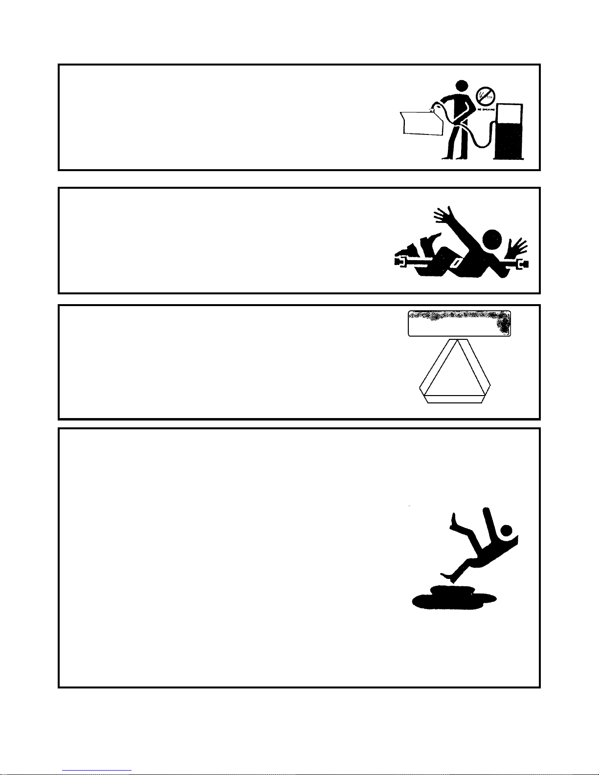
HANDLE FUEL SAFELY-AVOID FIRES
Handle fuel with care; it is highly flammable. Do not refuel the
Tractor while smoking or near open flame or sparks.
Always stop engine before refueling Tractors.
Always keep your tractor clean of accumulated grease, and debris.
Always clean up spilled fuel.
STAY CLEAR OF ROTATING SHAFTS
Entanglement in rotating shaft can cause serious injury or death.
Keep PTO shield in place at all times.
Wear close fitting clothing. Stop the engine and be sure PTO drive
is stopped before making adjustments, connections, or cleaning out
PTO driven equipment.
ALWAYS USE SAFETY LIGHTS AND DEVICES
Use of hazard warning lights and turn signals are recommended
when towing equipment on public roads unless prohibited by state
or local regulations.
Use slow moving vehicle (SMV) sign when driving on public road
during both day & night time, unless prohibited by law
PRACTICE SAFE MAINTENANCE
Understand service procedure before doing work.
Keep the surrounding area of the Tractor clean and dry.
Do not attempt to service Tractor when it is in motion.
Keep body and clothing away from rotating shafts.
Always lower equipment to the ground. Stop the engine.
Remove the key. Allow Tractor to cool before any work repair is
caused on it.
Securely support any Tractor elements that must be raised for
service work.
Keep all parts in good condition and properly installed.
Replace worn or broken parts. Replace damage/missing decals.
Remove any buildup of grease or oil from the Tractor.
Disconnect battery ground cable() before making adjustments on
electrical systems or welding on Tractor
6
Page 14
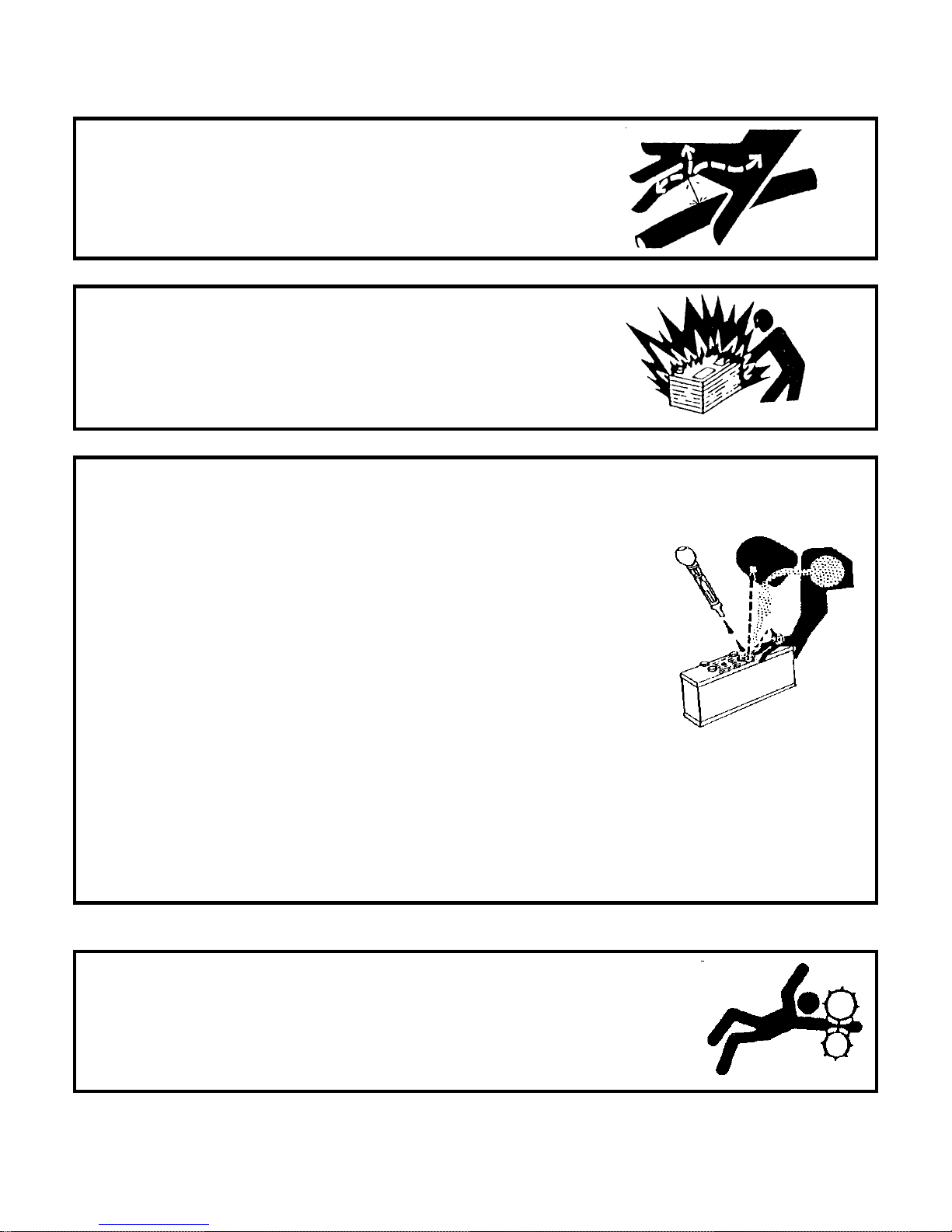
AVOID HIGH-PRESSURE FLUIDS
Escaping fluid under pressure can penetrate the skin causing
serious injury. Keep hands and body away from pinholes and
nozzles, which eject fluids under high pressure. If ANY fluid is
injected into the skin. Consult your doctor immediately.
PREVENT BATTERY EXPLOSIONS
Keep sparks, lighted matches, and open flame away from the top of
battery. Battery gas can explode.
Never check battery charge by placing a metal object across the poles.
PREVENT ACID BURNS
Sulfuric acid in battery electrolyte is poisonous. It is strong enough to
burn skin, cause holes in clothing and cause blindness if found entry
into eyes.
For adequate safety always;
1.Fill batteries in a well-ventilated area.
2.Wear eye protection and acid proof hand gloves
3. Avoid breathing direct fumes when electrolyte is added.
4. Do not add water to electrolyte as it may splash off causing severe
burns.
If you spill acid on yourself;
1.Flush your skin with water.
2.Flush your eyes with water for 10-15 minutes.
Get medical attention immediately.
SERVICE TRACTOR SAFELY
Do not wear a necktie, scarf or loose clothing when you work near
moving parts. If these items were to get caught, severe injury could result.
Remove rings and other jeweler to prevent electrical shorts and
entanglement in moving parts.
7
Page 15
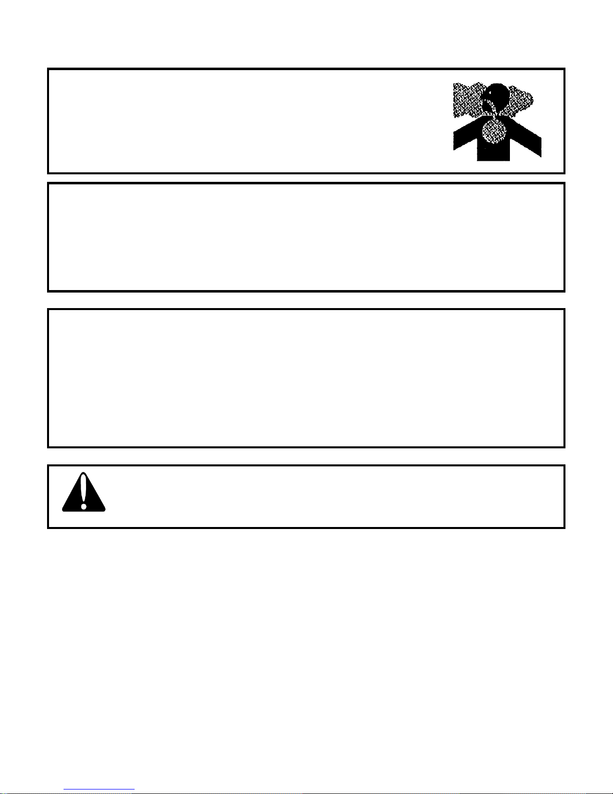
WORK IN VENTILATED AREA
Do not start the Tractor in an enclosed building unless the doors &
windows are open for proper ventilation, as tractor fumes can cause
sickness or death. If it is necessary to run an engine in an enclosed area
remove the exhaust fumes by connecting exhaust pipe extension.
TRACTOR RUNAWAY
1. The tractor can start even if the transmission is engaged position causing Tractor to runaway and
serious injury to the people standing nearby the tractor.
2. For additional safety keep the pull to stop knob (fuel shut off control) in fully pulled out position.
Transmission in neutral position, Foot brake engaged and PTO lever in disengaged position while
attending to Safety Starter Switch or any other work on Tractor.
SAFETY STARTER SWITCH
1. Clutch operated safety switch is provided on all Tractors which allow the starting system to
become operational only when the Clutch pedal is fully pressed.
2. Do not By-pass this safety starter switch or work on it. Only Authorized Dealers are
recommended to work on safety starter switch.
3. On some models Safety Starter switch is provided on transmission High-low shifter lever and in
PTO shifter lever.The tractor can be started only if High-low shifter lever is in neutral position.
Safety Starter Switch is to be replaced after every 2000 hours/4 years, whichever is earlier
Caution
8
Page 16

2.2 Safety Regulations
(1) Only those people who have been trained properly are allowed to drive a tractor.
(2) Before moving a tractor, you must observe whether there are obstacles on the road, especially whether
there is a man between the tractor and its trailer or its implement.
(3) Nobody is permitted to get on or alight from a moving tractor. While the engine is running, nobody
shall be allowed to work under the tractor for inspection and repair.
(4) When climbing or going down a steep hill, drive only at low gear. It is not permitted to shift gear
under such conditions.
(5) When a tractor is used for transportation, the left and right brake pedals must be locked together.
(6) Never make sharp turns when the tractor is being driven at high speeds. It is even more strictly
forbidden to make sharp turns with one side braked.
(7) Frequently inspect the tightness of bolts and nuts, fasten those connections such as the engine and the
chassis, driving wheels(or paddy wheels) and the axle shaft, steering gear and intermediate housing, etc..
Retighten any loosening of bolts and nuts.
(8) At the time of personnel changing shift, any troubles occurred with the tractor must be informed to the
workers of next shift. If necessary, the troubles must be eliminated before the tractor is assigned to work.
2.3 Important instructions
(1) Tractors that are newly delivered from the plant or rebuilt must undergo running – in process according
to the requirements stated in Chapter 3 before being assigned to work under normal load.
(2) Before starting the tractor, you must inspect the fuel system, electric system, cooling system and the
lubrication system. In any condition, it must not be permitted to fill unfiltered fuel into the fuel tank,
After starting the engine, you must ensure that the instruments or meters are working normally.
(3) When moving the tractor with implements attached, hydraulic lock of lifter must be turned to the
locking position.
(4) When hydraulic power output is used, the lift arm shall be at the lowest position and the cutoff valve
shall be turned in. On the other hand, if the attached implement is used for fields work, the cut-off valve
shall be turned out. It is not allowed to work both at the same time.
(5) When the tractor is used for stationary work through the use of belt and pulley system, the range shift
lever must be put in the neutral position, and the main gear shift lever must be in the 1st or 2ed gear
position, thus ensuring good lubrication of the front bearing of the 1st shaft in the transmission housing.
(6) This tractor is equipped with silicon rectifier alternator whose negative terminal is grounded.
Any mistake of wiring will damage the alternator and the regulator. It is strictly forbidden to make short
circuit tests by contacting the terminal to the ground, as this will destroy the diode. When the engine is
stopped, the key shall be turned to the position “0” to prevent the battery from continued discharging.
9
Page 17

2.4 (ROPS) Roll Over Protective Structures
Roll Over Protective Structures (ROPS)
ET 350 ECONO tractor is equipped with a frame for the protection of operators.
In the case of cab tractors the frame is incorporated in the cab structure.
The objective of the frame or cab structure is to protect the operator in the event of a roll over
and they are designed to support the entire weight of the tractor in that event.
ET 350 ECONO tractor’s ROPS frame or cab structure is designed and has been tested to meet
industry and or Government standards.
Included in these tests were all mounting bases and bolts or other fasteners.
DANGER
For ROPS frames to be effective and protect the operator, the seat belt provided must be
worn in order to keep operators within the ROPS protected area in the event of a roll over.
Failure to use the seat belt can still cause serious injury or death.
On some models the ROPS frame has a fold down feature, which can be used to enter low
buildings etc.
Take care when lowering the upper section of the ROPS frame and take extreme care while
driving the tractor with the ROPS frame lowered.
Do not wear the seat belt with the ROPS lowered and please remember that the fold down facility
is for special circumstances only and must not be lowered for general use.
Use of the tractor with the ROPS lowered can cause fatal injuries.
As the ROPS frame or cab together with the seat belt was designed to meet certain standards,
they must be maintained in good order and condition.
To achieve this objective, both the structure and the seat belt should be inspected on a regular
basis (every time the tractor is serviced)
In the event that the seat belt is damaged or frayed, it should be replaced and in the event that the
ROPS frame or any part of the mounting structure is damaged or cracked, the faulty component
must be replaced with a new unit.
Such a unit must meet all of the test criteria of the original unit.
Fitment of an inferior item or items affects the certification of the entire ROPS structure and the
effectiveness of the structure in the event of an accident.
Drilling or welding of the ROPS structure is forbidden.
10
Page 18
Damage of the ROPS
If the tractor has rolled over or the ROPS has damaged (such as striking an overhead object during
transport), It must be replaced to provide the original protection. After an accident, check for damages
to the 1.ROPS. 2.Seat 3.seat belt & seat mountings. Before you operate a Tractor, replace all
damaged parts.
DO NOT WELD, DRILL OR STRAIGHTEN THE ROPS
Never attach chains, ropes to the ROPS for pulling purposes; this will
cause the Tractor to tip backwards. Always pull from the Tractor drawbar.
Be careful when driving through door opening or under low overhead
objects. Make sure there is sufficient overhead clearance for the ROPS
Warning
fatal injuries
If the ROPS is removed or replaced, make certain that the proper hardware
is used to replace the ROPS and the recommended torque values are
applied to the attaching bolts
Warning
Warning
Always wear your seat belt if the tractor is equipped with ROPS
11
Page 19

Seat Adjusting Lever
Sliding seat
FOR Sliding seat
To select Seat position, move Adjusting lever and slide Seat closer to or away from Dash panel and
controls.
NOTE: Do not use solvents to clean the seat. Use warm water with a little detergent added.
Before operating a Tractor it is important to adjust the seat to the most comfortable position & check
whether it is properly locked in its position. Figure 1 identifies the seat fitted to your Tractor.
Check whether the seat properly locked in its position before driving the
tractor
Danger
Always use the seat belt when the ROPS is installed.Do not use the seat
belt if a foldable ROPS is down or there is no ROPS.Check the seat belt
regularly and replace if frayed or damaged
Danger
12
Page 20
2.5 SAFETY SIGNS
(Replace all missing, damaged or illegible signs)
GENERAL SAFETY INFORMATION
IMPORTANT: This “General safety Information” should be kept with the machine at all times as
reference data.
This symbol means ATTENTION! YOUR SAFETY IS INVOLVED.
The message that follows the symbol contains important information about safety.
Follow recommended precautions and safe operating practice.
WA RN IN G
• Before starting and operating know the operating
and safety instructions in the operators Manual
and on the tractor
• Clear the area of bystanders.
• Locate and know operation of controls.
• Start engine only from Operator’s seat with
depressed clutch pedal, transmission in the neutral
, PTO disengaged and hydraulic control in lower
position
• Slow down on turns, rough ground and slopes to
avoid upset.
FAILURE TO FOLLOW ANY OF THE INSTRUCTIONS ABOVE CAN CAUSE SERIOUS
INJURY TO THE OPERATOR.
• Do not permit anyone but the operator to ride
on the tractor. There is no safe place for rider.
• Lock brakes together, use warning lights and
SMV emblem while driving on roads.
• Lower equipment, place gear shift levers in
neutral, stop engine, remove the key and apply
parking brake before leaving the tractor seat.
• Air pressures are specified by the manufacturer
13
Page 21
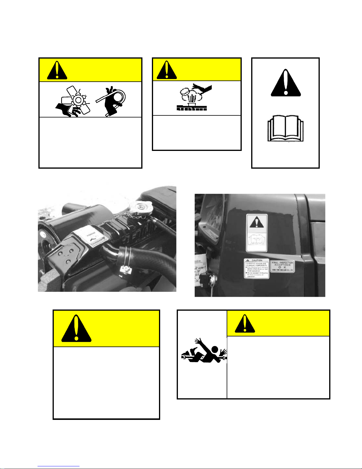
CAUTION
WARNING
KEEP HANDS AND
CLOTHING AWAY FROM
ROTATING FAN AND BELTS
TO PREVENT SERIOUS
INJURY
It is dangerous to remove
the radiator cap while the
system is hot .
Operator’s Manual
CAUTION
TO PROTECT ENGINE AND
HYDRAULIC COMPONENTS.
● Idle engine for 1 minute
before shut down or full load
operation.
● Do not exceed 1/2 throttle for
first 5 minutes of operation.
CAUTION
Rotating driveline contact can
cause Death
KEEP AWAY !
Keep all drive line.
Tractor and equipment shields in
place during operation
14
Page 22
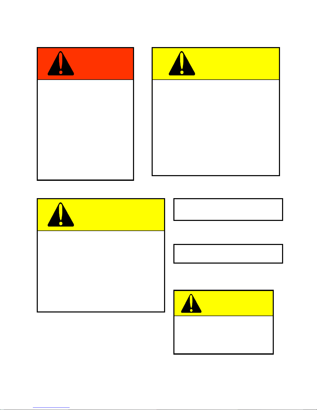
DANGER
WARNING
BLINDNESS CAN RESULT
FROM BATTERY EXPLOSION.
KEEP SPARKS OR OPEN
FRAMES AWAY FROM
BATTERY.
DO NOT JUMP START.
BURNS CAN RESULT
FROM BATTERY ACID.
IN CASE OF CONTACT
FLUSH IMMEDIATELY
WITH WATER .
WARNING
● Pull only from drawbar. Pulling from any
other point can cause rear overturn.
● Do not operate with unshielded PTO.
● Disengage PTO and stop engine before
servicing tractor or attaching and detaching
implements.
● When towing equipment use a Safety chain
FAILURE TO FOLLOW ANY OF THE
INSTRUCTIONS ABOVE CAN CAUSE
SERIOUS INJURY TO THE OPERATOR
OR OTHER PERSONS.
FRONT TYRE (6.5-16) PRESSURE
Air pressure: 23~25PSI
● Start engine only from operators seat.
If safety start switch is bypassed engine can
start with transmission in gear.
● Do not connect or short across terminal on
starter solenoid.
●Attach booster cables as shown on battery
decal and operators manual.
Starting in gear causing runaway can result
in serious injury.
REAR TYRE (11.2-24) PRESSURE
Air pressure: 10~12 PSI
WARNING
DO NOT REST FOOT ON
CLUTCH PEDAL.
MAY RESULT IN DAMAGE
TO CLUTCH ASSEMBLY.
15
Page 23
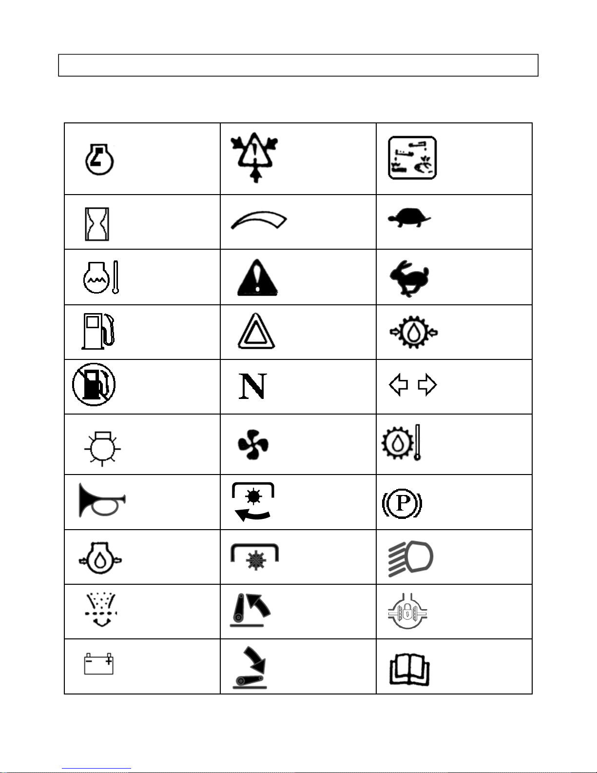
UNIVERSAL SYMBOLS
Some of the universal symbols have been shown below with an indication of their meaning
Engine speed
rev/minX100)
Hours,
recorded
Engine
coolant
temperature
Fuel level
Engine
Stop
control
Pressured-
open slowly
Continuous
variable
Corrosive
substance
”Tortoise”
Slow or
minimum Setting
”Hare” fast or
Warning
maximum
setting
Hazard
warning
Transmission
oil pressure
Neutral Turn signal
Transmission
Lights Fan
oil temperature
Power take
Horn
Engine oil
pressure
off engaged parking brake
Power
take off
Work lamps
Disengaged
Air filter Lift arm/raise Differential
lock
See
Battery charge Lift arm/lower
operator’s
manual
16
Page 24

CHAPTER 3. OILING AND RUNNING – IN PROCESS
3.1 Oiling and Fueling of Tractor
1. Oiling and Fueling Points of the Tractor
The oiling and fueling points of the tractor & Specification of fuel and lubricants are shown in Table 3-1
Table 3-1 Specifications of fuels and lubricants for tractor
Brand of fuel and lubricants
Fueling and Oiling points
Fuel tank No.0 light diese l fuel(GB252-87) No.10 light diese l fuel(GB252-87)
Engine oil sump,speed governor
Hydraulic lift, oil tank
Final drive, front driving axle
2 grease nipples in clutch bearings
At ambient temperature
above 0°C
No.HC-11 diesel engine oil
(SY1152-77)
Recommended foreign brand :
SAE 30 Oil or equivalent
No.HC-11 diesel engine oil
(SY1152-77)
Recommended foreign brand :
SAE 30 Oil or equivalent
90-GL-3 gear oil or gear oil
SAE 80
ZN-sodium based lubrication grease (GB492-87) Recommended
foreign brand : BRB3-MOBIL
At ambient temperature
below 0°C
No.HC-8 diesel engine oil
(SY1152-77)
Recommended foreign brand :
SAE 15W/30 Oil or equivalent
No.HC-8 diesel engine oil
(SY1152-77)
Recommended foreign brand :
SAE 15W/30 Oil or equivalent
85W-90-GL-3 gear oil or gear oil
SAE 80
15 grease nipples, including 1 nipple
in each of water pump bearing, left
and right steering arm, two front
driving shafts and front/rear bush
seats ; 2 nipples in each of axle
bushing of clutch pedal &
int e rme dia te housing, 4nipple s in
connec tion rod ends
ZG-2 calcium based lubrication grease (GB491-65) Recommended
foreign brand : AA2, B2-MOBIL
2. Instructions on the Use of Fuel
(1) Fuel must be settled for at least 48 hours before used.
(2) Fuel must be carefully filtered when it is handled
(3) It is not permitted to wipe any containers or fuel line connections with felts, cotton waste or used cloth.
17
Page 25

3.2 Running-in of a New Tractor
A new tractor or a rebuilt tractor must be properly run-in so that the fitting and contacting surface of
the parts can be well contact with each other, resulting in that the tractor can withstand loads more
reliably without the early worn or damaging of the parts.
1. Preparations before Running-in
(1) Inspect and tighten all accessible bolts and nuts.
(2) Fill up lubricating oil, fuel and water to the rated level.
(3) Clean all external parts of the tractor.
2. Running-in of the Tractor
A. Idling running-in of the engine (10 min)
Start the engine according to the specified procedures. With the raising of water temperature and
oil temperature, gradually increase the speed. Carefully inspect whether there are leakages of
water, oil or gases. Listen to the engine for any abnormal noise. Be careful to watch the water
temperature gauge, oil pressure gauge, and ammeter to see if they are working normally.
B. Running-in of hydraulic hitch system (10min)
When the tractor is properly attached with its implement and the engine is kept at its rated speed,
operate the control handle and thus raise and descend the implement for at least 20 times.
To prevent possible damage of the implement, this test must not be carried out on ground with
hard surface.
C. Running-in of tractor without load (2 hours)(Table 3-2)
After starting the tractor according to specified procedures, run the tractor without load according
to the following specifications.
During running-in of the tractor without load, it is required to make turns both to the right and to
the left. It is also required to make turns with brakes. In such running-in procedures, the following
should be noted :
(1) Observe and listen to the engine, power trains, wheels and steering system to see whether they
are working properly.
(2) Notice whether the clutch, brake and gear – shifting are working normally and conveniently.
(3) Observe whether the instruments, meter and the electric equipment are working normally.
When any abnormality or troubles are found, they shall be analyzed immediately to find out the
causes. Then only after removal of the troubles, can the running-in procedure be resumed.
D. Running-in of tractor with load (48hours)
Running-in the tractor with load is the procedure that make tractor to work with a certain load.
Load and speed must be increased from low to high as specified in the Table 3-3
18
Page 26
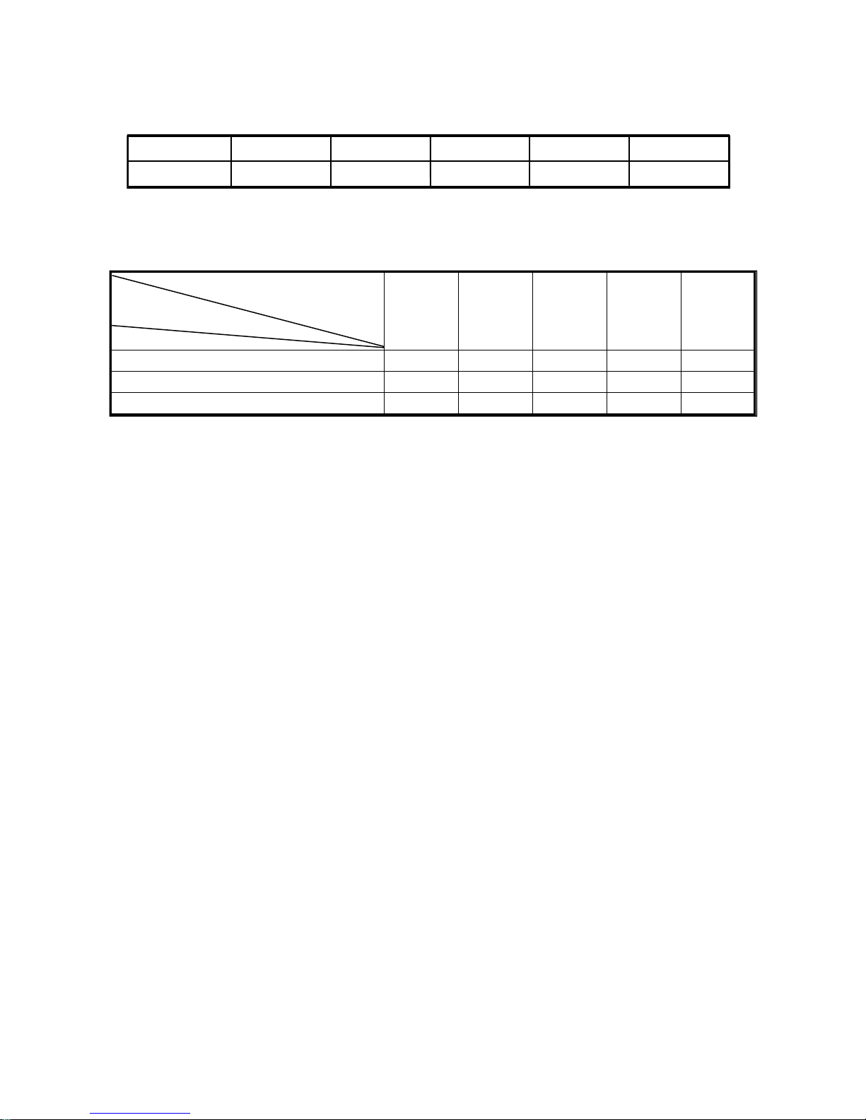
Table 3-2 Time to run-in tractor without load
Speed 3rd 4th 5th 6th Rev.1
Time (min)2030303010
Table 3-3 Time in hours of the tractor running-in under load
Running-in
time(hrs)
Load(Kgf)
170 (1/4 load)
340 (1/2 load)
510 (3/4 load)
Ge ar of
Transmission 3rd 4th
345517
355518
355 13
5th 6th total
Under conditions when it is hard to provide tractor with specified load, it is permissible to replace
the load with same equivalent work. During the running-in periods, any trouble and working
condition should be recorded in detail.
3.3 Work on the Tractor after Running-in
(1) After running-in, drain immediately the oil cells in different parts of the tractor chassis while it
is still warm. Then fill some kerosene or diesel fuel into the Oil cells, run the tractor for 2~3min in
the 2nd and reverse 1st speed. Raise up and descend down the hitch for a few times. Stop the
tractor and immediately drain out the flushing oil. Once again the cells are filled with clean new oil.
(2) While the engine is still warm, drain the oil from the oil sump. After cleaning the oil sump and the
oil filter, fill new clean oil into the engine.
(3) Inspect and tighten all accessible bolts and nuts.
(4) After inspecting and adjusting, add grease to the nipples.
(5) Record all findings and conclusions. Only after this, can the tractor be delivered to the customers
for normal usage.
19
Page 27

CHAPTER 4. OPERATION FOR TRACTOR
4.1 Controls and Instruments
The controls and the instruments of the tractor are shown in Fig.4-1, Fig.4-2,Fig4-3
1. Preheating Starting switch 10 (Electricity lock)(Fig.4-2)
Insert key into the switch. Turn the key clockwise, the electrical equipment and battery are connected,
the preheating plug is preheated, then continue to turn it to the “start” position.
2. Front head light switch 23
Push the switch to the upside, the front head light(upper beam) is turned on, and its pilot lamp is
turned on ; (No.1) When in the neutral position, the front head light is turned off.
3. Steering light switch
Push the switch to the upside, the left steering light (is turned on,) and the left steering pilot lamp
in the gauge is turned on; Push the switch to the downside, the right steering light (is turned on,) and
the right steering pilot lamp is turned on; when in the neutral position, the steering light and steering
pilot lamp are turned off.
4. Hand throttle 26 (Fig.4-2)
Pull the hand throttle backward, the fuel flow will increase. While push it forward, fuel flow will
decrease.
5. Shut-off full rod 22 (Fig.4-2)
Pull rod backward, the engine will be stopped. Then push it forward to the original position.
6. Foot throttle 15 (Fig. 4-2)
Depress the pedal down, the fuel flow will increase : loosen it, the fuel flow will decrease .
7. Decompressing lever 12 (Fig. 4-2)
Turning the lever clockwise is for the decompressing position.
8. Main and sub-shifting levers 19,20 (Fig. 4-2)
The positions of main and sub-shifting levers are as shown in the mark carved in the top surface of
upper front cover of transmission housing. Shift the two levers into different positions respectively,
various forward and reverse speeds can be obtained. The neutral position is in the middle.
9. Clutch pedal 21(Fig. 4-2)
Depress the pedal, the release arm will touch stop screw, thus the clutch is disengaged.
20
Page 28
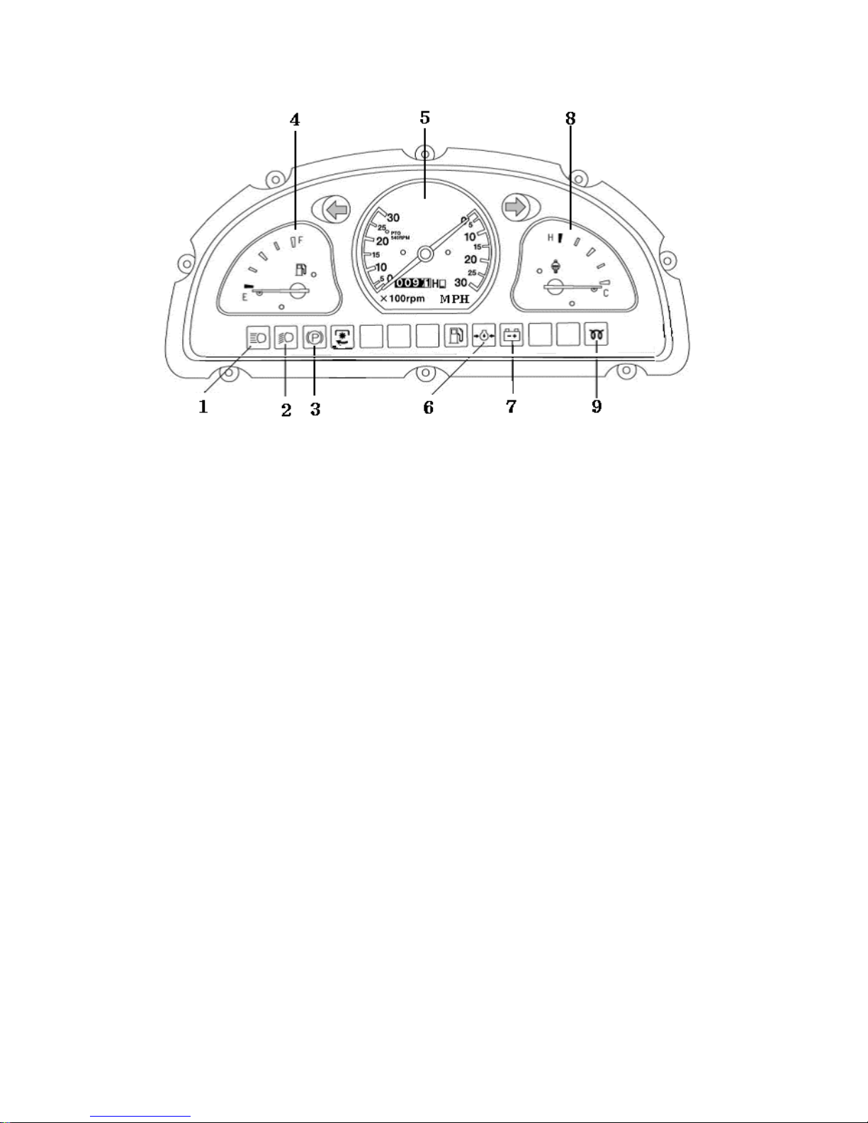
►WARNING LIGHTS
(Fig.4-1) Instruments and Warning Light
1. Front head pilot lamp 2. Tail pilot lamp 3. Brake pilot lamp 4. Oil gauge
5. Rated speed/Hour gauge 6. Oil pressure pilot lamp 7. Charge pilot lamp
8. Water temperature gauge 9. Starting/Preheating pilot lamp
10. Left and right brake pedals 13, 17 (Fig. 4-2)
Depress the left brake pedal to brake the left driving wheel, the left turning radius of the tractor can be
reduced. Depress the right brake pedal to brake the right driving wheel, the right turning radius can be
reduced.
11. Charge pilot lamp7 (Fig.4-1)
Turn the key clockwise, the electrical equipment is connected, the changing lamp is lighting and starting
the engine;When the battery is being changed, the pilot lamp is turned off. If it is turned on, it means the
change system has problem.
12. Water temperature gauge 8 (Fig.4-1)
The gauge shows the water temperature of the cooling system. The normal water temperature is in the
range of 70~90°C
13. Rated speed gauge 5 (Fig.4-1) The gauge shows the rated speed of engine. And accumulate working
time of engine.
14. Oil pressure pilot lamp 6 (Fig.4-1)
Turn the key clockwise, the electrical equipment is connected, the lamp is lighting and starting the
engine, the lamp will be turned off, it means the oil pressure is normal; otherwise oil pressure is
abnormal.
15. Brake lock plate 14 (Fig.4-2)
The brake lock plate can connect left and right pedals as a whole so that the left and right driving wheels
can be braked simultaneously when the pedals are depressed.
21
Page 29
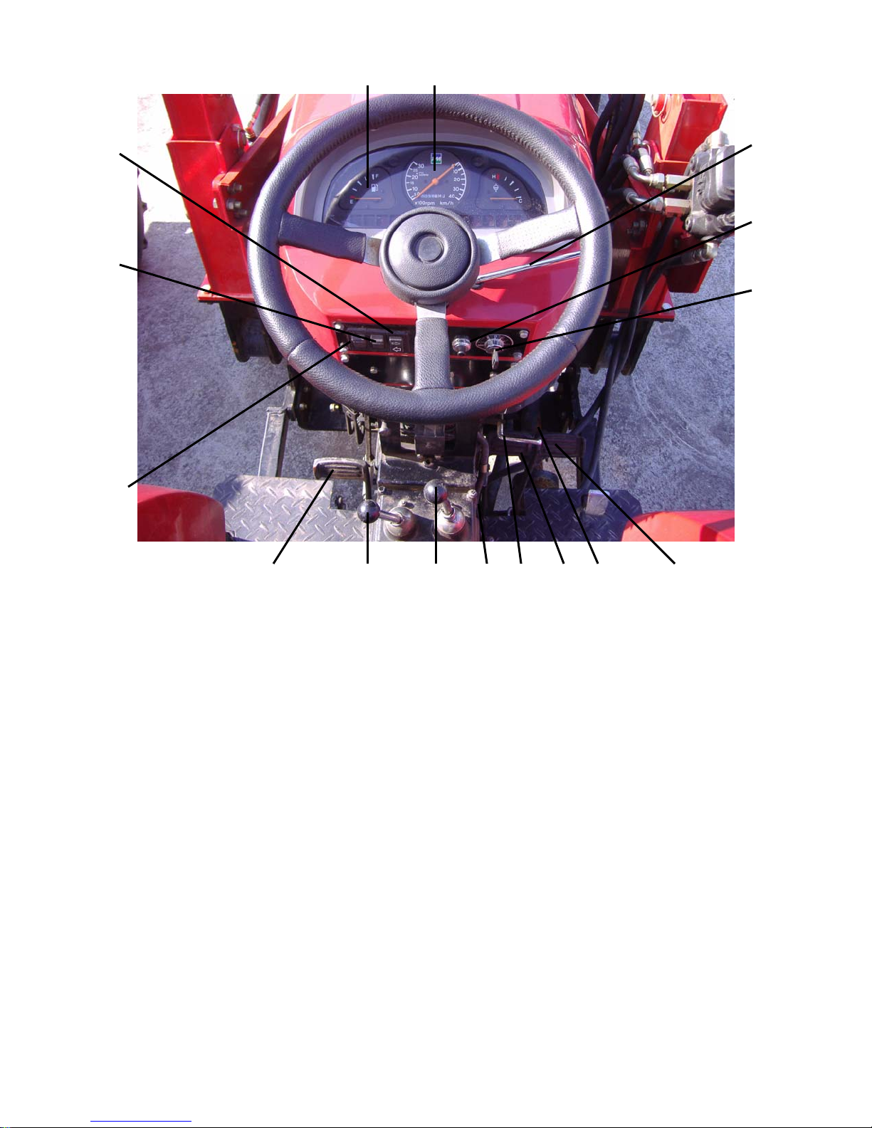
4
5
25
24
23
26
10
11
21
20 19 17 13
12
1418
Fig.4-2 Tractor controls
10. Electricity lock 11. Horn button 12. Decompression handle 13. Brake pedal RH
14. Lock plate 15. Foot throttle 16. Draft control 17. Brake pedal LH
18. Brake pawl 19. Main gear shift lever 20. Range gear-shift lever 21. Clutch pedal
22. Shut-off pull rod 23. Front head light switch 24. Tail light switch 25. Steering pilot lamp switch
26. Throttle handle
22
Page 30
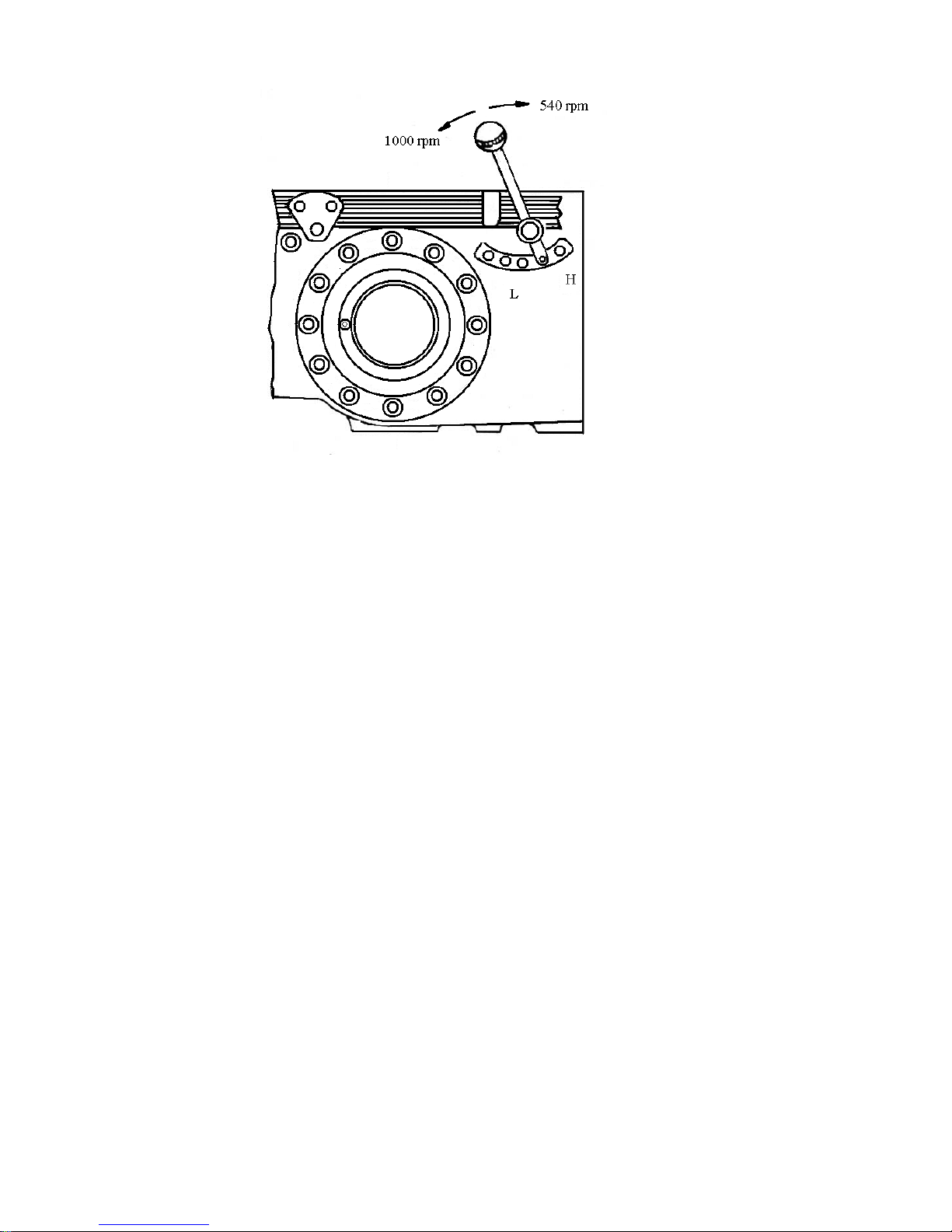
Fig.4-3 Control lever of PTO shaft
16. Brake lock pawl 18 (Fig.4-2)
The brake lock pawl is used when the tractor is parked on a slope or in storage for a long period. Push
the pawl up to lock brake pedals so that the brake can be kept in braking. Pull the pawl back, the barking
will be eliminated.
17. Fuel gauge
Turn the key clockwise, the electrical equipment is connected, it indicates how much fuel in the fuel
tank.
18. Control lever of PTO shaft (Fig.4-3)
For the engagement of the power take-off shaft, shift the lever forward or backward for high or low
speed respectively. Place the lever in middle position to disengage the shaft.
19.Implement lowering speed control valve
This valve has the following function ; (1) Adjust the lowering speed of the implement. (2) Lock the
implement to keep it in lifting position. (3) Block the oil circuit fuming to cylinder and then ready for
doing hydraulic power take-off.
20. Lifter control handle 16 (Fig.4-3)
The upper segment on the sector plate is for position control, the middle for combined control and the
lower for draft control.
23
Page 31

4.2 Operating and Driving
1. Starting the Engine
A. Preparations for the starting
(1) Perform daily inspection and service (see chapter 6 for details). Remove all troubles discovered.
(2) Put the shifting levers at the “neutral” position.
(3) Open the fuel cock on the sediment cup.
(4) Push the fuel feed pump to remove air in the supply system.
(5) Turn the crankshaft a few circles with the crank.
B. Starting procedure
(1) Put the throttle handles at the position of maximum fuel supply.
(2) Insert the key into electric lock, turn it to starting position for about 5 seconds. Then engine will start.
C. Points to be noticed and auxiliary measures for starting.
(1) The key should be turned to the change position after starting the engine.
(2) When it is difficult to start the engine, put the decompressor to the decompression position and key to
the preheating position. After about 10 seconds, the key is turned quickly to the starting position.
After another 5 seconds the decompression mechanism is invalidated and the engine will be started.
(3) For each starting, the electric starter shall not be run over 5 seconds. When the starting failed for the
first time, it can be tried again after the elapse of 2 minutes. When the engine failed to start for 3 times,
the cause shall be investigated and removed.
(4) When the atmospheric temperature is lower than 0°C, the engine will be hard to start. It is
permissible to add hot oil of 75~80°C into the oil sump. Also, hot water of 80~90°C can be added into
the radiator.
D. Operation of the engine after starting.
(1) After starting the engine, immediately return throttle handle to the “Idling” position for a few minutes
(2) After idling, the engine speed is gradually increased to the medium speed range for about 10 seconds.
To warm up the engine, the speed is again increased to 1000~1500r/min.
(3) Only after the water temperature has reached over 60°C, can the engine be permitted to work at full
load.
24
Page 32

2. Start to move the Tractor
(1) Loosen the fixing pawl of the brake pedals.
(2) Depress the clutch pedal and put the shifting lever at the required speed.
(3) Gradually depress the throttle and raise the engine speed.
(4) Sound the horn if necessary. Be sure that nothing will obstruct the movement of the tractor.
(5) Gradually engage the clutch, thus starting the tractor.
3.Driving The Tractor
A.Selecting the speed
It will increase the productivity and the economical gains when the speed is properly chosen.
For the proper usage of the various speeds, see Table 4-1.
The 1st, 2nd and 3rd speeds can not be used for plowing and harrowing (even more so with the purpose
to get greater draft force), otherwise, the transmission system will be seriously overloaded to cause
damage of the tractor.
B. When driving, take notice of the following points:
(1) Notice frequently the readings of the meters. Water temperature gauge, normally at 70~90°C. Oil
pressure gauge, normally at 0.2~0.4MPa. Ammeter, normally at the middle or in the positive range.
Any undue readings shall be investigated and the trouble removed.
(2) Listen carefully to the engine. If there be any abnormal or knocking sound, the engine shall be
immediately stopped to the remove the abnormalities.
(3) Sharp turns can be made only when the tractor is at low speed. When the tractor is working in the
fields, particularly in the paddy fields, turn with single side braking can be made. In transportation
work, it is strictly forbidden to make single side braking to make sharp turn at high speeds.
(4) It is forbidden to continuously run the engine under overload when black fumes will come out of the
exhaust pipe.
(5)It is not permitted to rest the foot on the clutch pedal or brake pedal, nor is it permissible to drive
down-hill in the neutral gear or with the clutch disengaged. When passing over obstructions, must
decrease throttle or put the gear-shift lever to low position. It is not allowed to control the speed of
the tractor with maneuvering of the brakes fail to work, the tractor must be stopped for repairing.
(6) When the tractor is working in the paddy fields, if the front end of the tractor tends to rise up, the
clutch pedal should be immediately depressed to cut off the driving torque, thus avoiding the danger
of overturning the tractor.
25
Page 33

4. Stopping the engine and the Tractor
(1) Decrease the throttle opening and depress clutch pedal. When necessary, depress also the brake
pedal, thus halting the tractor.
(2) Put the shifting levers to the neutral position, release the clutch pedal and lock the brake pedal if
necessary.
(3) Idling the engine for something until the water temperature drops to below 70°C, then pulling the
shut-off pull rod to stop the engine. It is strictly forbidden to stop the engine suddenly from high
temperature.
Table 4-1 Usage of various speeds of tractor
gear 1st 2nd 3rd 4th 5th 6th 7th 8th
Usage
Rotary tillage,
Harvesting
Plowing, harrowing and seeding Transportation
Tr ansp lanta tio n
4.3 Operation of the Working facilities
1. Operation and Control of the PTO Shaft (see Fig.4-3)
(1) Put the control lever of the PTO shaft at neutral position. Remove the PTO shaft guard and connect
reliably the PTO shaft to the implement.
(2) Depress the clutch pedal. Depending on the requirement of the implement the control lever of the
PTO shaft is set at the high or low position
(3) Gradually release the clutch pedal to start the implement. First run the implement at low speed to
inspect the the operation condition. If it runs normally, it will be put to work in the normal condition.
2. The Operation and Control of the Hydraulic Lift System (see Fig 5-12, 5-13)
(1) The main technical specifications of hydraulic lift system
Type : Partial separated units
Working depth control :Position control, draft and position combined control, float control
Type of pumping :CB310(right-handed)(ET 350 ECONO)
Displacement of oil pump(mL/r) :10;14
Change over valve :Two-position, Y-way sliding type
CB310(left-handed)(ET 350 ECONO)
26
Page 34

Opening pressure (MPa) of
system release valve : 14±0.5
cylinder release valve : 18±0.5
Rated lifting capacity(N) : 7850(at lower draw-bar hitch point)
Dim. and Qty. of oil outlets : M18X1.5;1
(2) To operate the hydraulic lift
When a tractor operates in the field, the control of working depth is selected according to its
attachments and job requirements. There are three ways available for working depth control through
putting the control handle at different positions on the sector plate, which include position control,
draft and position combined control and float control. The upper segment on the sector plate is for
position control, the middle for combined control and the lower for draft control.
There are a hydraulic output connection and a control valve for lowering speed, located on the
cylinder head in the front end of hydraulic lift. The lowering speed control valve also hand wheel
clockwise will slow down the lowering speed. As the hand wheel is turned to the end, the pressure oil
in the cylinder will completely sealed to lock the hydraulic system. Hydraulic locking is necessary
when a tractor attached with implement travels from one spot to another. When the hydraulic output is
used, the lifting arm must be at its lowest position and the hydraulic system must be completely locked
to enclose oil from entering into the cylinder. To supply hydraulic output, operate the handle.
4.4 Operation of Electrical Equipment
The electrical equipment of the tractor is used to start engine, meet the needs of giving indication signals
and lighting for operation at night, etc.. Therefore it is very important to use the electrical equipment
correctly.
1. Battery
A. Preparation
(1) Clean the surface of a new battery. Screw off the plastic cover and make the air hole on the cover
open.
(2) The specific gravity of the electrolyte used in the battery is 1.26(15°C) in the tropics, 1.28(15°C) in
temperate zone and 1.29(15°C) in frigid zone. Fill the battery with the electrolyte when it cooled to
25~30 °C. After a standstill of 20 minutes, the battery can be used.
(3) The electrolyte level should be 10~15mm above the protecting plate.
(4) If the battery is stored over a year, it should be changed with electric current of 11.5A for 5 hours.
27
Page 35
B. Routine use
(1) In routine use the dust and dirt on the battery surface should be cleaned periodically and keep the
terminals and all contacts in good connecting condition.
(2) Keep the air hole on the plastic cover unimpeded so as to protect the battery from trouble because
of too much gas in the battery.
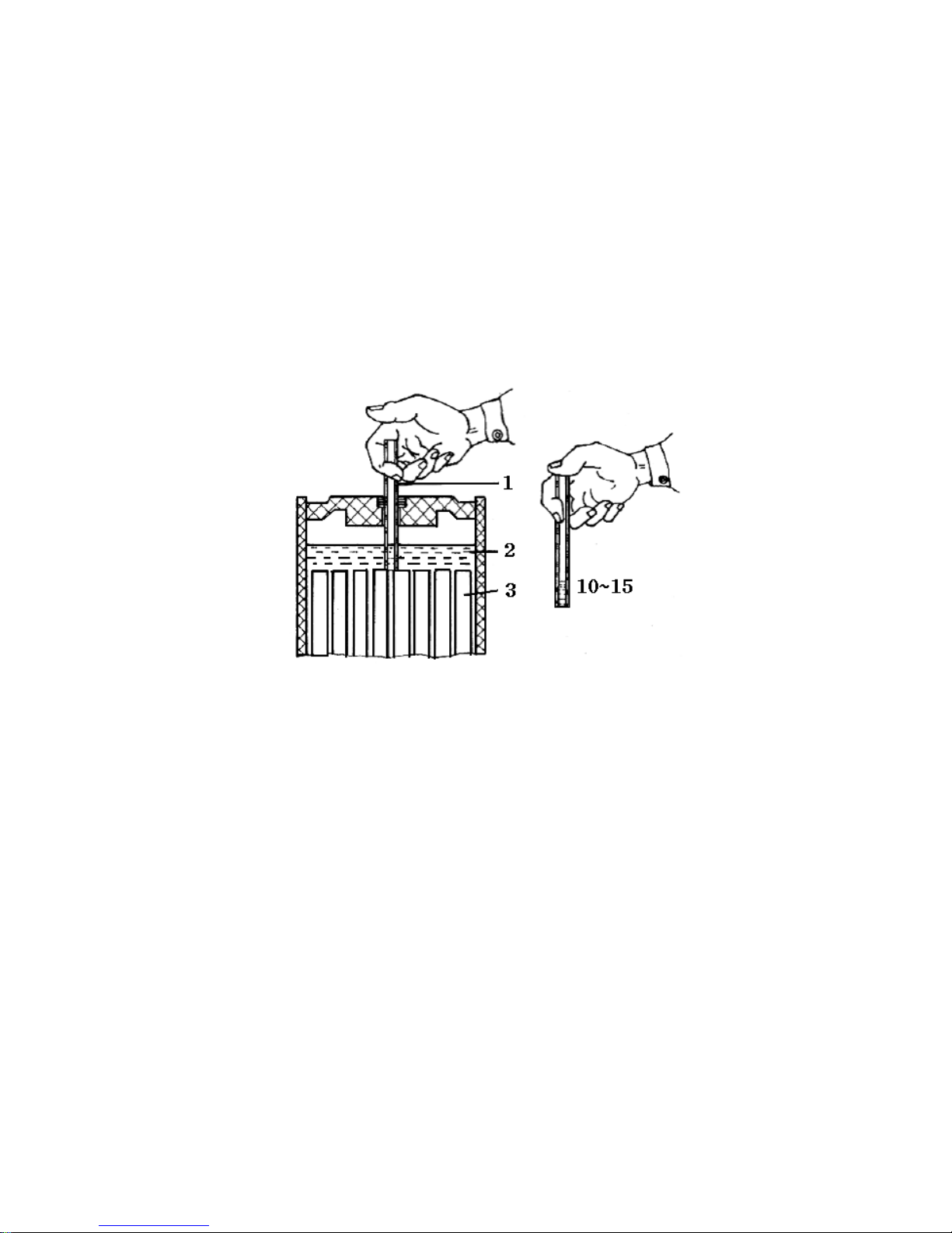
(3) Check the height of electrolyte level periodically (Fig.4-4). The height of electrolyte level is within
10~15mm in the measuring tube. If the electrolyte is below that level, add distilled water. In case
electrolyte overflows under unusual conditions, the electrolyte mixed with reference to local
temperature can be added.
Fig 4-4. Checking the electrolyte level
1.Grease tube 2. Electrolyte 3. Plate
(4) Keep the generator and regulator in good working condition and make the consumed electric
power be added in time.
(5) Never check the electricity storage by the method of short circuit so as to protect the battery from
being damaged.
(6) The battery should have enough electric power. When the voltage value of a cell is below 1.7v,
the battery should be recharged.
(7) In order to prolong the service life of the battery, the horn should not be used frequently and
starting engine should be carried out according to the regulations.
2. The Generator and Regulator.
28
Page 36

(1) Generator is used with regulator.
(2) The generator is connected with ground by negative pole. The generator is connected with the
regulator and the battery by negative pole. They can not be connected in wrong way or in counter
direction. Otherwise the generator and regulator may be damaged.
(3) Keep the generator clean and contacts between wires in good condition.
(4) Check the tension of the generator belt regularly and adjust it if necessary.
(5) When the tractor is to be stopped, the key in the preheating starting switch should be moved to “O”
position to disconnect the field coil of the generator and the battery so as to avoid the battery
discharging to the generator.
Note : Checking the generator by short circuit is seriously prohibited, otherwise the silicon rectifier and
the regulator may be damaged.
3. The Starter
(1) Keep the starter clean and the contacts between wires in good condition.
(2) The time for each starting should not be over 10 seconds. The shortest interval between two
startings must be more than 2 minutes. If the engine can not be started after several startings,
the trouble should be found out and removed, then the engine can be restarted.
(3) If the engine is started in winter, it should be preheated and then can be started with the starter.
29
Page 37

CHAPTER 5 IMPORTANT ADJUSTMENTS
5.1 Important adjustment Data of Engine
The main adjustment data of engine is shown in Engine Operation Manual.
5.2 The Components of Clutch
(1) Its Structure
For the structure of double-action clutch, refers to Fig.5-1, and for its components see Table 5-1,
where the code numbers indicated with asterisk refer to components specially designed for double-
action clutch.
A double-action clutch incorporates two clutches. The master clutch at the rear consists of clutch
shaft,clutch driven disk assembly, clutch pressure plate and the rear Belleville spring. The PTO
clutch is located in the front, and consists of clutch shaft, clutch pressure plate, clutch driven disk
and the front Bellevile spring. The clutch cover and the fixed clutch pressure plate provide
positioning and supporting for the rear clutch. Power is delivered from the engine through the master
engagement sleeve and PTO engagement sleeve respectively to the input shaft of the transmission
and PTO, allowing for separated power transmission for tractor running and power takeoff.
(2) Adjustment, Control and Working Principle
A.When the clutch assemble is secured to the flywheel by six bolts M 10X70, the following
adjustments should be made.
a. Adjust the spherical nut on the bolt until a distance of 66 mm is reached between the working
plane of release levers and the side surface of flywheel and the differences in working plane of
the three release levers should not exceed 0.15mm. Lock the spherical nut with thin nut after
adjustment.
B. The free travel and working travel should be adjusted after installation:
a. Adjust the relative position of adjusting fort in the push-rod of clutch until a free travel of
A=4~7mm is reached at the clutch pedal.
b. Adjust the height of bolt M 10X45 until a working travel of B=25~36mm is reached at the
clutch pedal.
30
Page 38
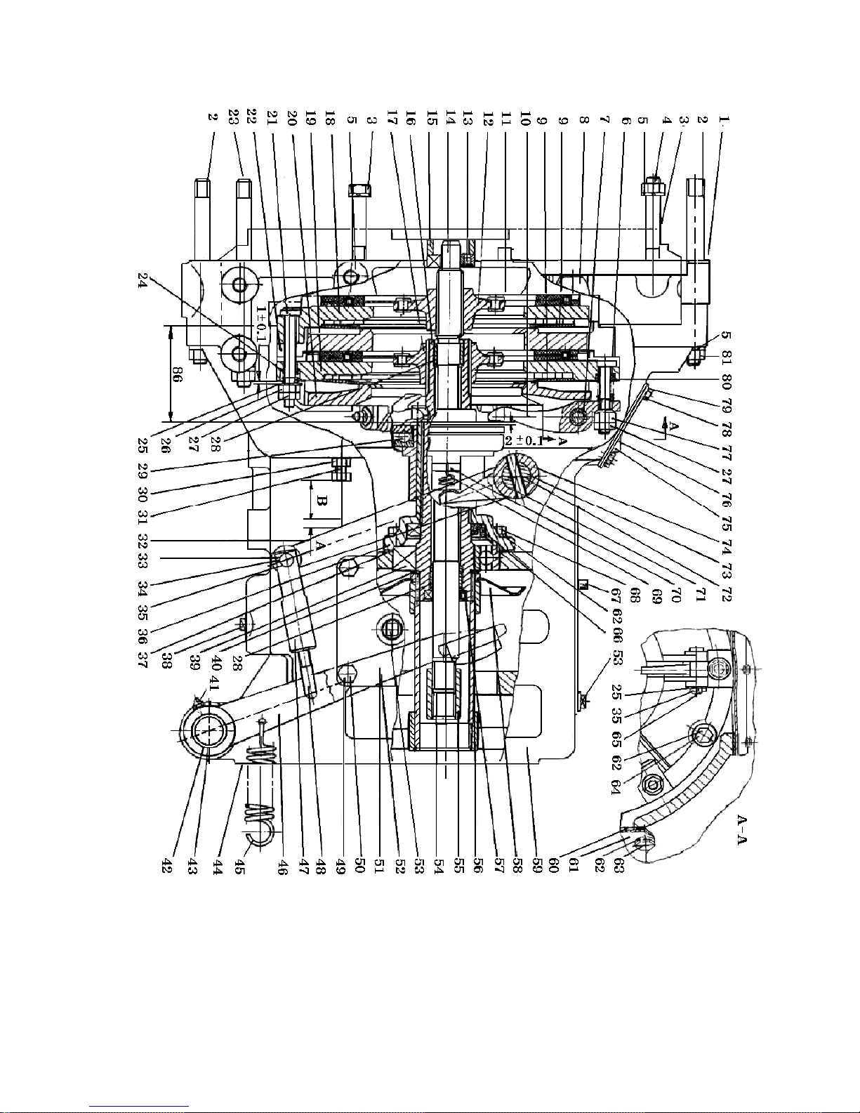
Fig. 5-1 Double-action clutch
Free travel:A=4~7mm (at clutch pedal)
Working travel:B=25~36mm (at clutch pedal)
31
Page 39
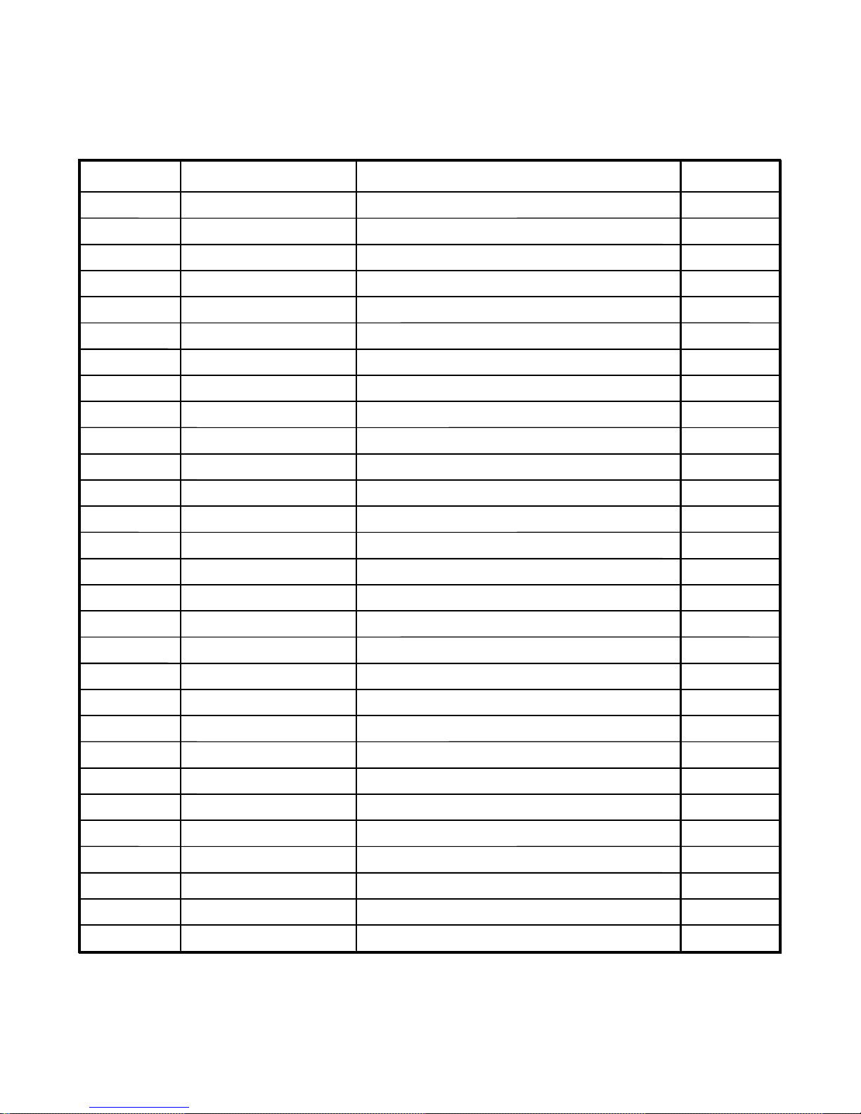
Table 5-1 Detailed Component List of Double-action Clutch
No. Code Description Qty
1 25.21.111 Paper gasket, bridge casing 1
2 GB898-88 Stud AM 12X150 2
3 GB5782-86 Bolt M 12X75 4
4 GB898-88 Stud AM 12X70 1
5 GB898-87 Spring washer 12 10
6 250.21.111* Adjusting screw 3
7 250.21.120* Bush 3
8 25.21.229 Plug 1
9 250.21.104* Bellevile spring 2
10 250.21.128* Release lever 3
11 GB5782-86 Bolt M 12X95 1
12 25.21.013 Drive plate assembly, clutch 1
13 GB278-89 Ball bearing 1
14 250.36.102* Shaft, PTO clutch 1
15 25.21.230 Spacing sleeve 1
16 250.36.101* Shaft, master clutch 1
17 250.21.011* Driven plate assembly, master clutch 1
18 250.21.105* Pressure plate, PTO clutch 1
19 250.21.107* Pressure plate, master clutch 1
20 250.21.109* Clutch cover 1
21 250.21.101* Pull-rod 3
22 250.21.106* Fixed pressure plate, PTO shaft 1
23 GB898-88 Stud AM12X170 2
24 250.21.102* Pressure spring 3
25 GB97.1-85 Flat washer 10 7
26 GB6173-86 Nut fine M 10X1 6
27 GB6173-86 Nut fine M 10X1 6
28 SF-1* Bush 220 2
29 * Release bearing 9688213 1
32
Page 40
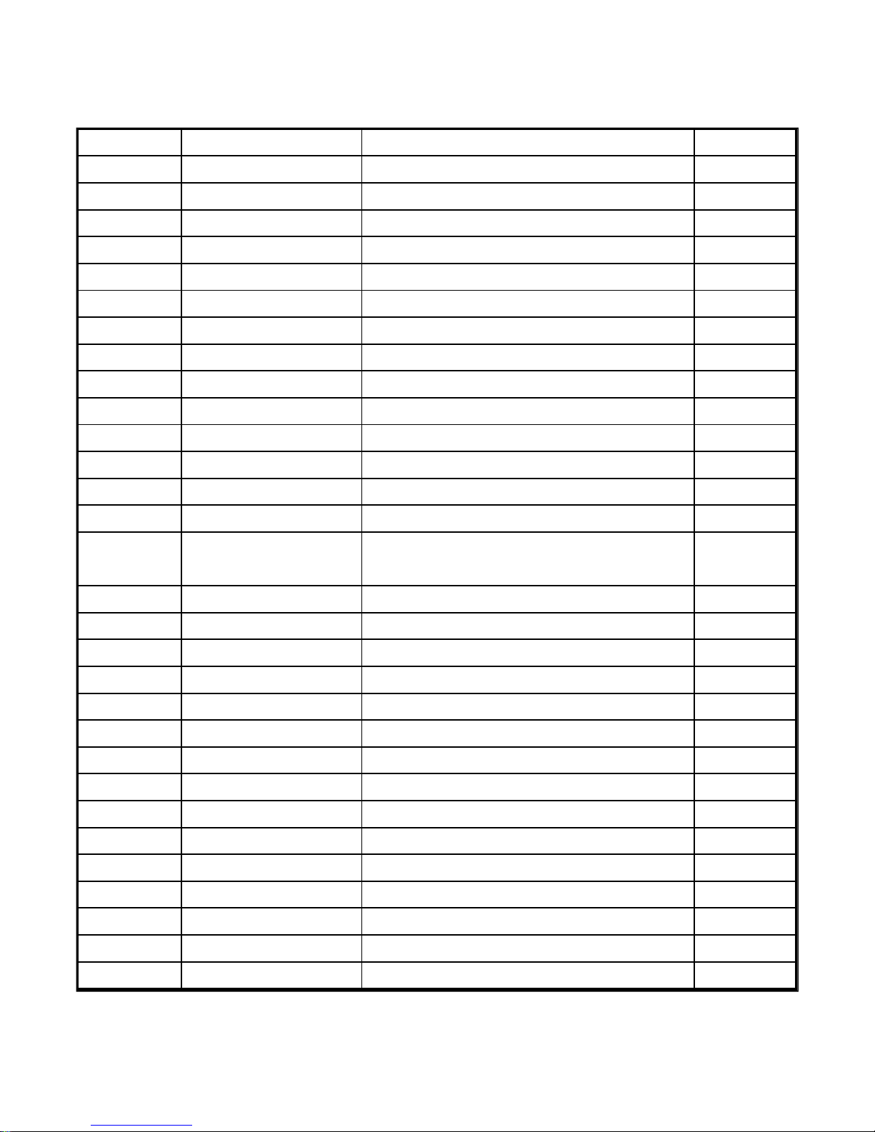
Signal No. Code Description Qty
30 GB6170-86 Nut M10 1
31 GB55781-86 Bolt M10X45 1
32 250.21.116*-A Release arm, clutch 1
33 GB882-86 Pin shaft B8X30 1
34 GB97.1-86 Flate washer 8 1
35 GB91-86 Splite pin 3.2X20 5
36 250.36.125* Support, release bearing seat 1
37 250.36.129* Paper gasket, release bearing seat 1
38 ZBT32001.5-87 Screw plug II-1/4" 1
39 GB276-89 Ball bearing 210 1
40 GB894.1-86 Retaining ring, shaft 1
41 GB1152-79 Oil cup 3
42 25.21.136 Bush 1
43 25.21.116 Bush 3
44 25.21.140
Pa p er gaske t intermedia te ho using to
transmission housing
45 25.21.110 Clutch pedal spring 1
46 25.21.130* Clutch pedal 1
47 25.21.107 Adjusting fork, clutch puch-rod 1
48 250.21.114* Clutch push-rod 1
49 GB5781-86 Bolt M8X20 6
50 GB93-87 Spring washer 8 6
51 250.36.136* Side cover 1
52 250.36.137 Paper gasket, side cover 1
53 ZBT32001.5-87 Screw plug II-1/2" 2
54 GB119-86 Cylindrical pin 1
55 250.36.122* Joint sleeve, PTO shaft 1
56 250.36.016 Main joint sleeve weldment assy 1
57 GB9877.1-88 Metal-cased oil seal 22X36X10 1
58 250.36.017* Oil thrower weldment assy 1
1
59 250.36.135* Intermediate housing 1
33
Page 41
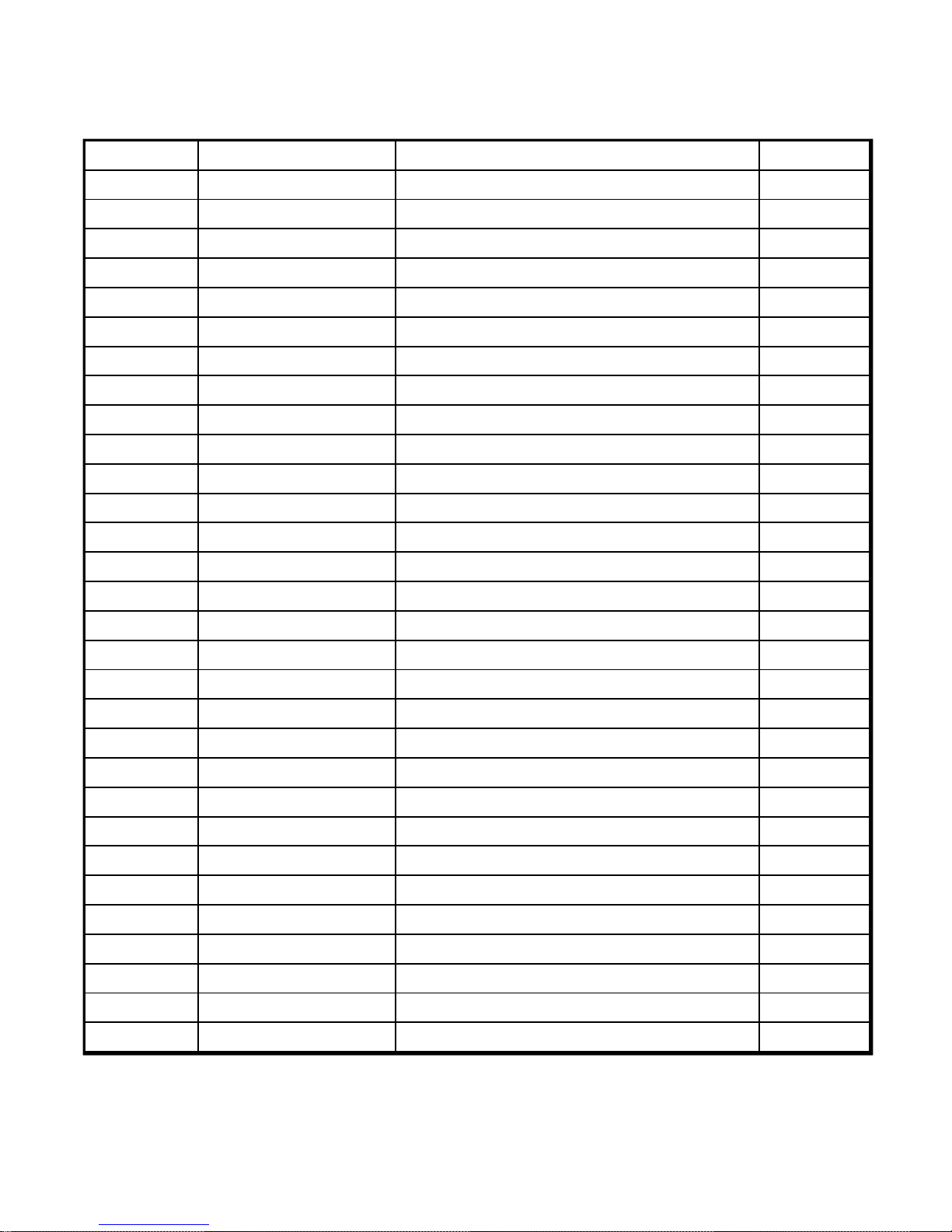
Signal No. Code Description Qty
60 250.36.131* Rubber pad, cover 1
61 250.36.128* Watch window cover 1
62 GB93-87 Spring washer 10 12
63 GB5781-86 Bolt M10X20 2
64 GB5782-86 Bolt M10X70 6
65 GB882-86 Pin shaft B10X45 3
66 GB9877.1-88 Metal-cased oil seal 42X62X12 1
67 GB119-86 Pin D8X16 2
68 GB5781-86 Bolt M10X30 4
69 250.21.113* Return spring, release bearing seat 2
70 250.21.131* Release bearing seat 1
71 GB876-86 Spring pin 10X40 2
72 250.21.117 Release fork rod, clutch 1
73 25.21.115 Bush 1
74 250.21.112* Release fork 1
75 250.36.154* Upper cover 1
76 250.36.155* Gasket, upper cover 1
77 250.21.118* Spherical nut 3
78 GB5781-86 Bolt M6X15 6
79 GB93-87 Spring washer 6 6
80 250.21.108* Return spring 3
81 GB6170-86 Nut N12 5
34
Page 42
Note : The asterisk “*” indicates that this component is specially designed for use on double-action
clutch.
C. When the first of clutch pedal is depressed, the three release levers actuate the clutch pressure plate
through adjusting bolts to disengage the master clutch, interrupting power transmission to the running
system on the tractor, while the clearance (1±0.1) at the three pull-rods is eliminated and the clutch for
power take-off continues to work. Only the clutch pedal is further depressed, can the full-rod drive the
pressure plate of PTO clutch to disengage the PTO clutch. The second stage of disengagement cuts off
power transmission to power take-off shaft. As the clutch pedal is released, the PTO clutch is first
engaged and then the master clutch. The user can be trained to accurately distinguish the stage of
release. For apprentice drivers who are not skillful enough to operate the clutch and only want to
release the first working stage, a limiting mechanism on the clutch release lever can be used to control
the first stage working travel.
(3) Repair and Maintenance
A. The clutch should engage smoothly and disengage thoroughly. If any problem is found, check and
adjust relevant clearance if necessary.
B. During technical maintenance Class 111, oil in the rear of bridge casing (the same as used in the
transmission) should be changed. The oil level should be at the lower edge of the screw hole to ensure
that the oil thrower weldment can provide lubrication for bearing.
5.3 Adjustment of Transmission
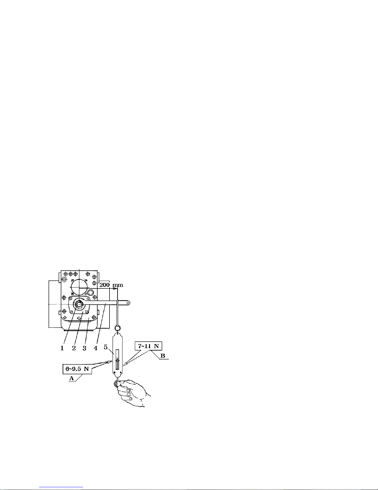
A. The spring scale reading after preloading the
front bearing of the second shaft
B. The spring scale reading after preloading the
differential bearing and that of the front bearing
of the second shaft.
1. Circular nut
2. Front bearing cover of the second shaft
3. Transmission housing 4. Special wrench
Fig. 5-2 Preloading of front bearing of the second
5. Spring scale
shaft and that of the differential bearing
35
Page 43
(1) For the preloading of the front bearing No.27305 of the 2nd shaft and that of the differential bearing
No.7210, see Fig.5-2. The preloading of bearing No.27305 requires a frictional torque of
1.2~1.9N*m,Which corresponds to a reading in force on the spring scale of 6.5~9.5 N.
The preloading of bearing No.7210 requires a frictional torque of 0.9~1.4 N*m. When this is
transformed to the 2nd shaft and added to it the preloading torque of bearing No.27305
(1.2~1.9 N*m), the corresponding reading on spring scale should be 7~11 N.
(2) Make sure that the axial play shall be less than 0.1mm.
This can be made by means of changing the number and thickness of the shims.
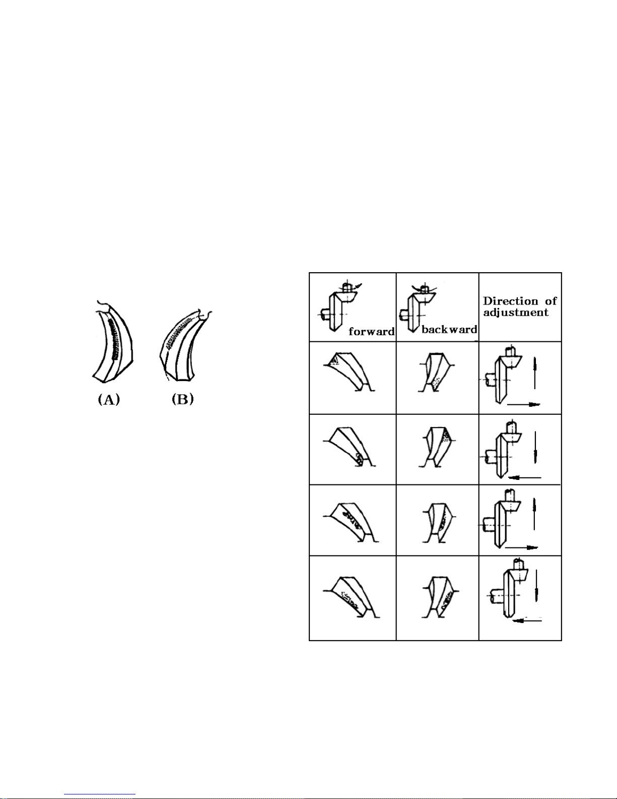
(3) For the condition of teeth contact, see Fig. 5-3
Fig. 5-3 Ideal condition of teeth contact of
spiral bevel gears when the tractor is
driven forward
(A-Small gear, B-Big gear)
Fig. 5-4 Adjustment of teeth contact condition
for spiral bevel gear
36
Page 44
In case of abnormal teeth contact condition, it is possible to make adjustments according to Fig. 5-4.
The solid line with arrow head shows the adjustment of teeth contact, while the dashed line shows the
adjustment of backlash.
(4) When it is assured of normal teeth contact condition, the backlash could be adjusted to 0.1~0.2 mm.
5.4 Adjustment of Brakes
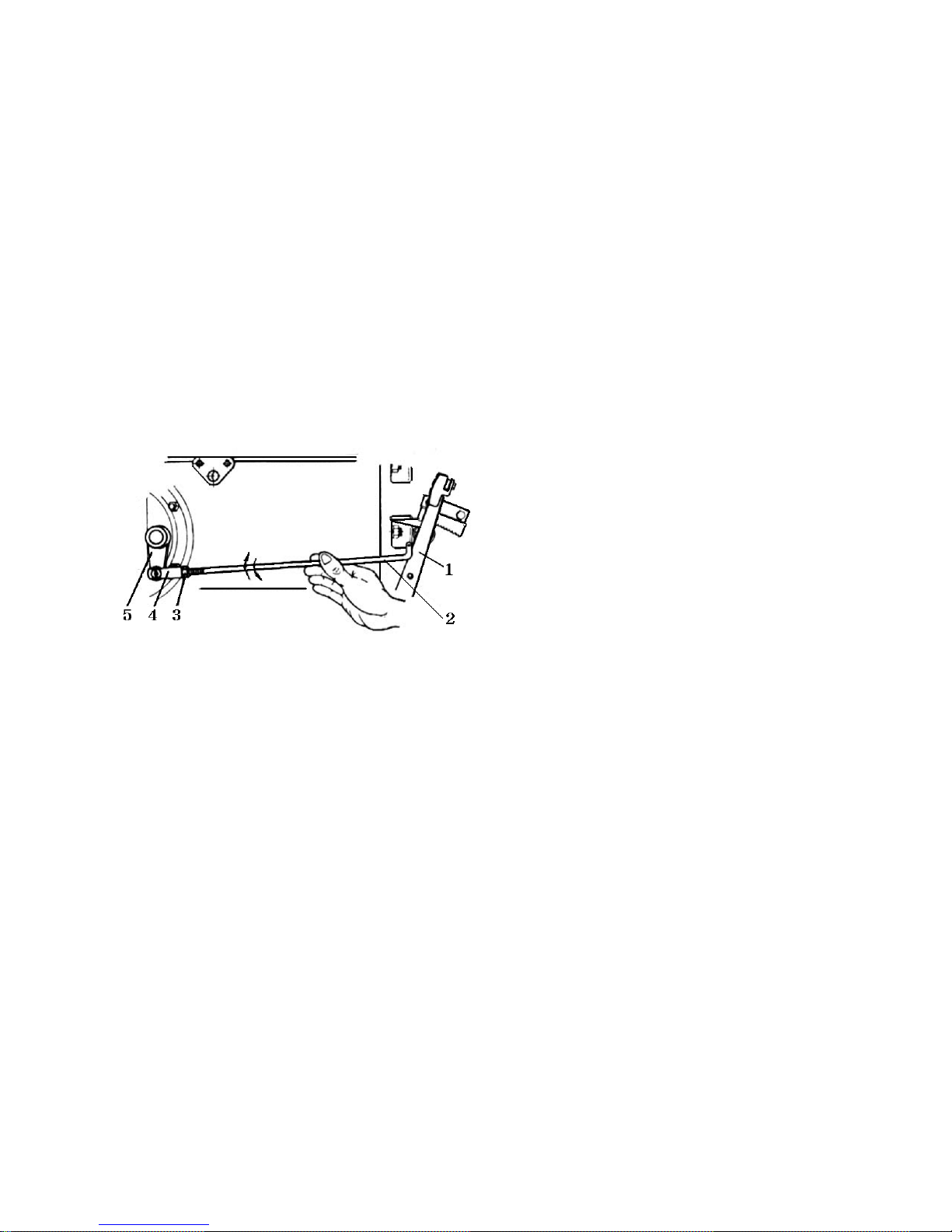
The adjustment of the brakes is shown in Fig. 5-5. The length of the control rod is adjusted so that
when the top of the brake pedal is subjected to a force of 13 N. the travel should be 20~40 mm.
It shall be assured also that the left and right brakes will work equally effectively.
Fig. 5-5 Adjustment of brakes
1. Brake pedal
2. Control rod
3. Lock nut
4. Adjusting fork
5. Rocker arm of cam
5.5 Adjustment of Final Drive
For adjustment of preloading of the drive shaft bearings, see Fig. 5-6
(1) Place of piece of fuse wire of about 2mm diameter between the inner bearing cover and the bearing
No.7307. Place also a set of adjusting shims of a total thickness of about 1.5 mm. After mounting the
inner bearing cover, tighten the bolts with a torque of 40~50 N*m, to press the fuse into a flat plate.
(2) Dismount the bearing cover, take out the fuse plate and measure its thickness.
(3) Deduct the thickness of the fuse plate from the total thickness of the shims. This will form a set
of shims, the use of which will result in clearance or interference of less than 0.1 mm. Assemble the
shims and bearing cover and tighten the bolts with a torque of 40~50 N*m.
37
Page 45
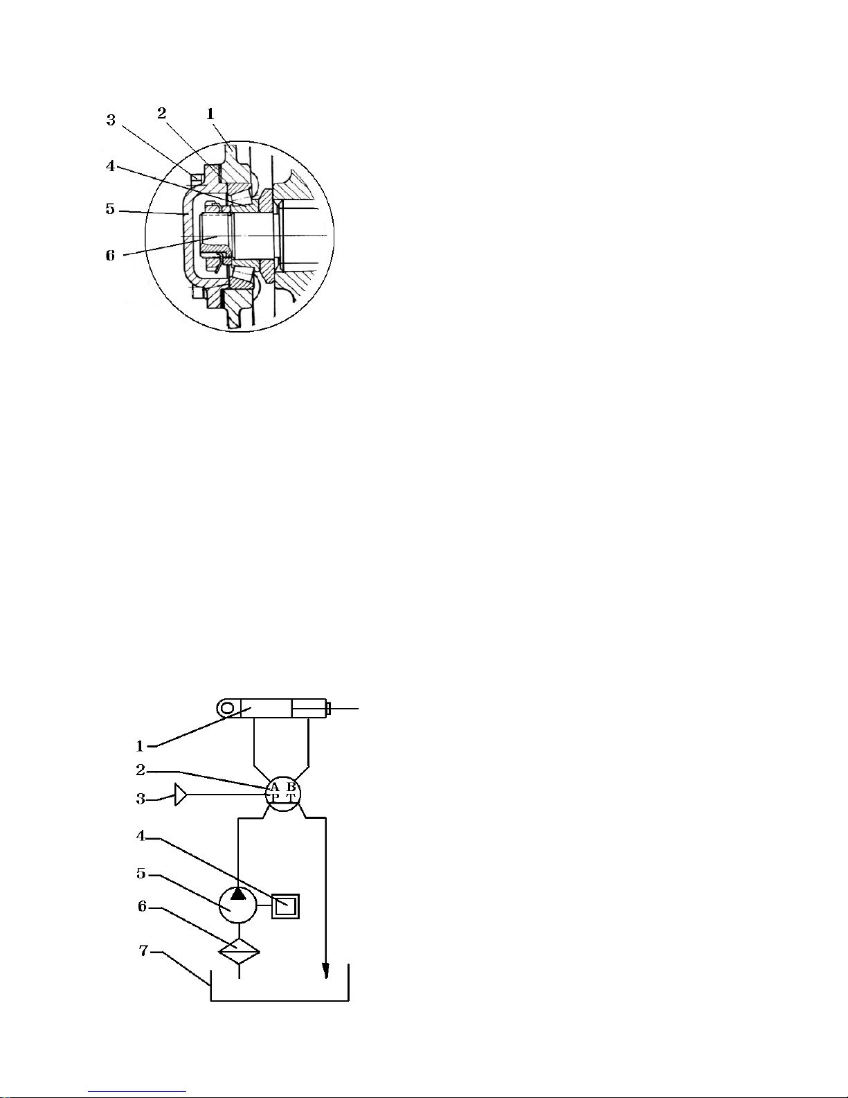
Fig. 5-6 Adjustment of preloading the bearings of the drive shaft
1. Housing of final drive
2. Adjustment shims of the drive shaft
3. Bolts
4. Bearing No. 7307
5. Inner bearing cover of drive shaft
6. Drive shaft
5-6 Fully hydraulic steering system
The tractor is adopted fully hydraulic steering system. It mainly consists of BZZ1-80 hydraulic
steering gear, hydraulic oil tank, HLCB-D08/06 pump, hydraulic oil cylinder. Its theoretical diagram
please see Fig. 5-7, the structural diagram please see Fig. 5-8. The flow rate of hydraulic oil is a
constant 6ml/rev and 8L/min. The rated working pressure is 10MPa.
From the pump 12 constant flows hydraulic pressure oil to hydraulic steering gear 2, and the steering
wheel is motionless, then the hydraulic pressure oil returned oil pipe 10 from steering, and flows to
hydraulic oil tank 23. The steering wheel is working, the hydraulic oil flows into the left side or
right side of steering cylinder 16, which make the direction adjusted.
Fig. 5-7 Principle of hydraulic steering
1. Steering cylinder
2. Fully hydraulic steering gear
3. Steering wheel
4. Diesel engine
5. Front gear oil pump
6. Filter
7. Steering oil tank
38
Page 46
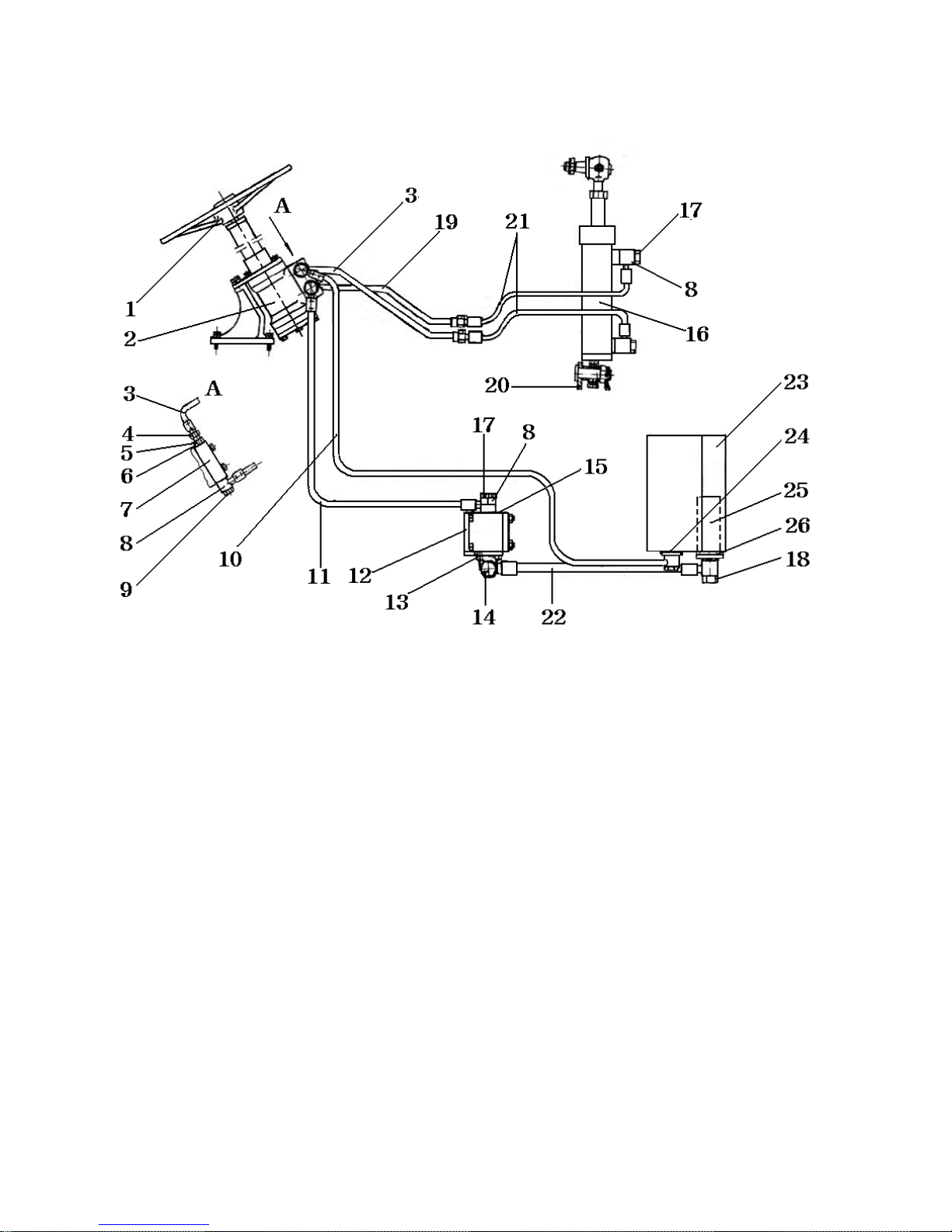
Fig. 5-8 Connection of pipelines and hydraulic components
1. Steering wheel assy 2. Hydraulic steering gear mounting assy
2. Steering gear A-cylinder iron pipe 4. O-ring 13X1.9 5. Steering gear ports A and B joint
6. Multi-sealed washer 2 7. Connecting block 8. O-ring 24X2.4 9. Hollow bolt M20X1.5X43
10. Return oil pipe, steering gear 11. Inlet oil pipe, steering gear 12. Gear pump
13. Union 14. Hollow bolt M24X1.5X48 15. Multi-sealed washer 18
16. Steering cylinder assy 17. Hollow bolt M18X1.5X43 18. O-ring 28X2.4
19. Steering gear B-cylinder iron pipe 20. Front seat weldment assy
21. Steering cylinder tube 22. Steering gear oil pump inlet tube
23. Hydraulic oil tank weldment assy 24. O-ring 35X3.1 25. Filter weldment assy
26. O-ring 55X3.1
39
Page 47
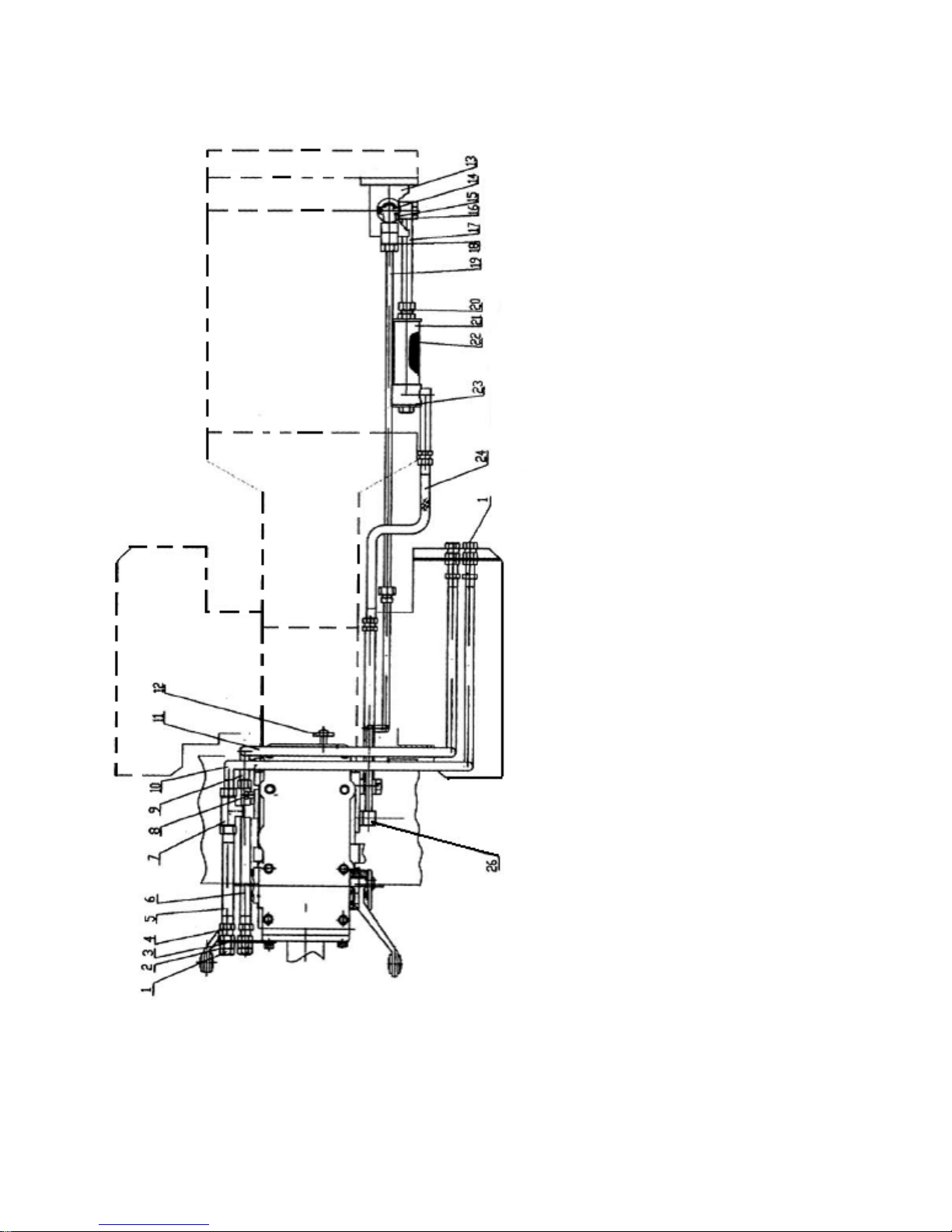
5-7 Lifter hydraulic tube line system (Fig. 5-9)
1.Plug M22X1.5 2. Multi-washer 22
3. Straight joint M18X1.5-M22X1.5
4. O-ring 16X2.4
5. Hydraulic PTO pipe assy I
6. Hydraulic PTO pipe assy II
7. Hydraulic PTO joint assy I
8. Cut-off valve
9. Hydraulic PTO joint assy II
10. Hydraulic PTO joint assy III
11. Hydraulic PTO joint assy IV
12. Implement lowering speed control valve
13. Gear pump
14. Union
15. Oil outlet joint
16. Hollow bolt M24X1.5X48
17. Hollow bolt M24X1.5X48
18. O-ring 28X2.4
19. Lifter front pressure oil tube assy
20. O-ring 24X2.4
21. Filter housing assy
22. Filter element assy
23. O-ring 55X3.1
24. Low pressure rubber hose assy
25. Quick joint
26. Lifter high pressure oil tube assy
Fig. 5-9 Lifter hydraulic pipeline system
40
Page 48
The gear pump is installed on the engine. The oil tube of front loader shall be reliably connected with
the joint 25 of oil pressure outlet tube at first when the front loader is working, then put the lift arm at
the lowest position to exhaust remaining oil in the lift cylinder. Then turn on the adjusting rod of cut-off
valve clockwise to shutoff the oil supply into the oil cylinder. Either the draft control or the position
control handle adjusted to the “lifting” position. The front loader can be operated now. When the rear
hydraulic output is used, turn out two plugs 1, exchange the joint 25, it shall be turned in and reliably
connected. Turning the hand wheel clockwise will slow down the lowering speed. As the hand wheel
is turned to the end, the pressure oil in the cylinder will completely sealed to lock the hydraulic system.
Hydraulic locking is necessary when a tractor attached with implement travels from one spot to another.
5.8 Adjustment of the Tread
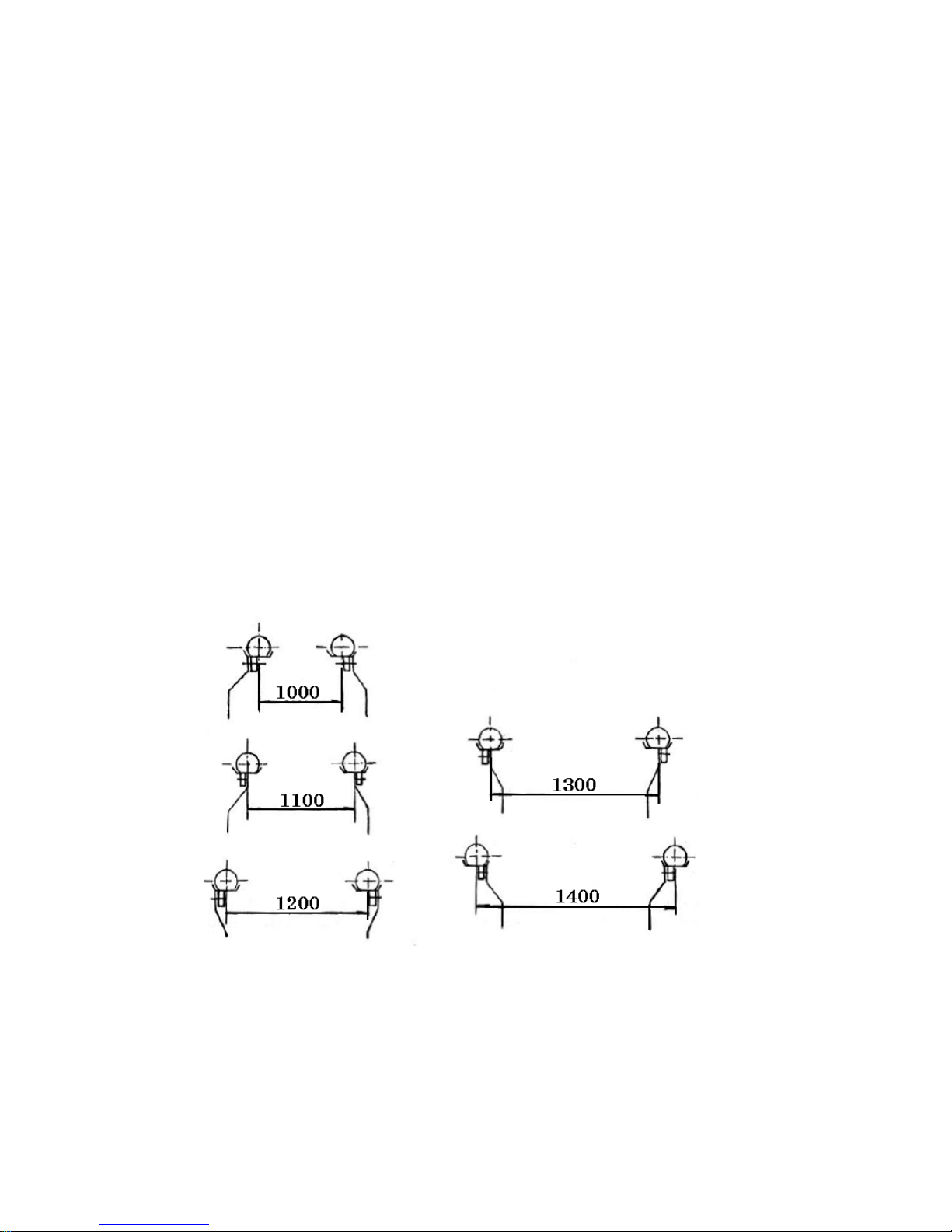
(1) The distance between the front wheels can be adjusted to have 4 different lengths by means of the
telescopic tubes within the range of 1100~1400 mm.
(2) For the driving wheels, the tread may be changed by the wheel spokes and the wheel rims.
This makes it possible to have 5 different lengths of the tread within the range of 1000~1400 mm.
Please see Fig. 5-10
Fig. 5-10 Tread adjustment of the driving wheel
41
Page 49
5.9 Adjustment of the Lifter
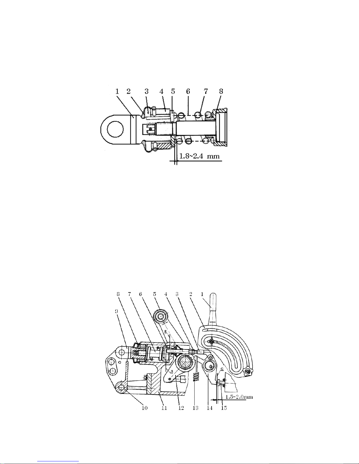
(1) For the adjustment of spring assembly of draft control system, see Fig. 5-11.
After the spring assembly is put together, the clearance between the washer and the shoulder of the
spring rod should be 1.8~2.4 mm
Fig. 5-11 Adjustment of draft control spring assembly
1. Upper link connector 2. Dustproof cover 3. Pin 4. Nut 5. Washer of draft control spring
6. Spring rod 7. Draft control spring 8. Spring seat
(2) For the adjustment of push rod of the draft control system, please see Fig. 5-12. Put the draft
control spring assemble into the lift housing, make its front end to contact surface E of the housing,
and insert the locating pin.
Put the draft and position control handles in the vertical position, adjust the length of the push rod, and
make sure that its end will contact the surface A of the spring rod. At same time, make the control end
G of the draft control lever have a clearance of 1.5~2 mm with the end surface of the main control \
valve at moment the main control valve in outmost position.
Fig. 5-12 The adjustment of the push rod of the draft control system
42
Page 50
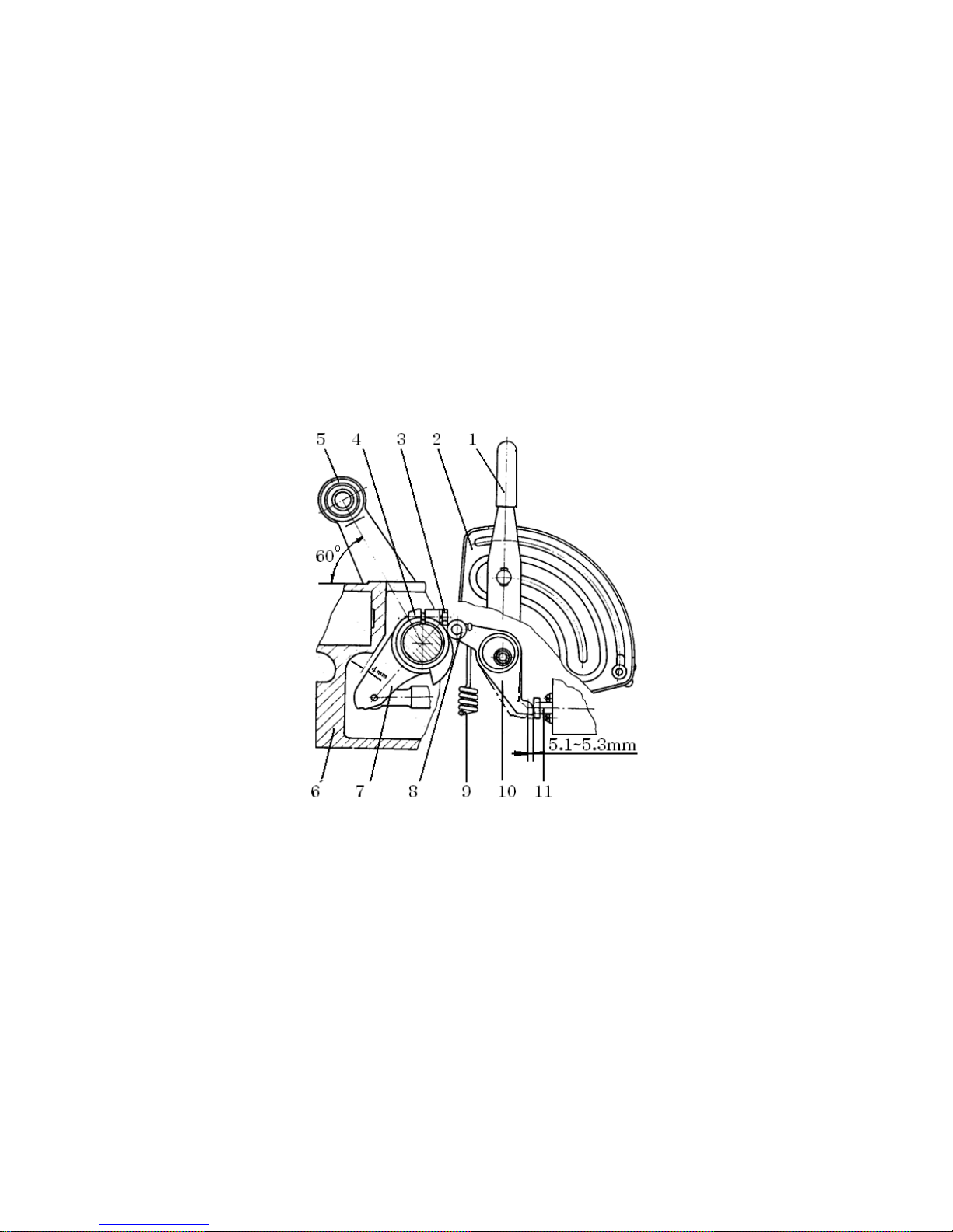
1. Draft control handle 2.Sector plate 3. Link arm 4. Lock nut 5. Lift arm
6. Push rod of the draft control system 7. Spring rod 8. Dowel rod
9. Spring assembly of draft control 10. Rocker arm of upper hitch point 11. Lift housing
12. Inner lift arm 13. Pull spring 14. Draft control lever 15. Main control valve
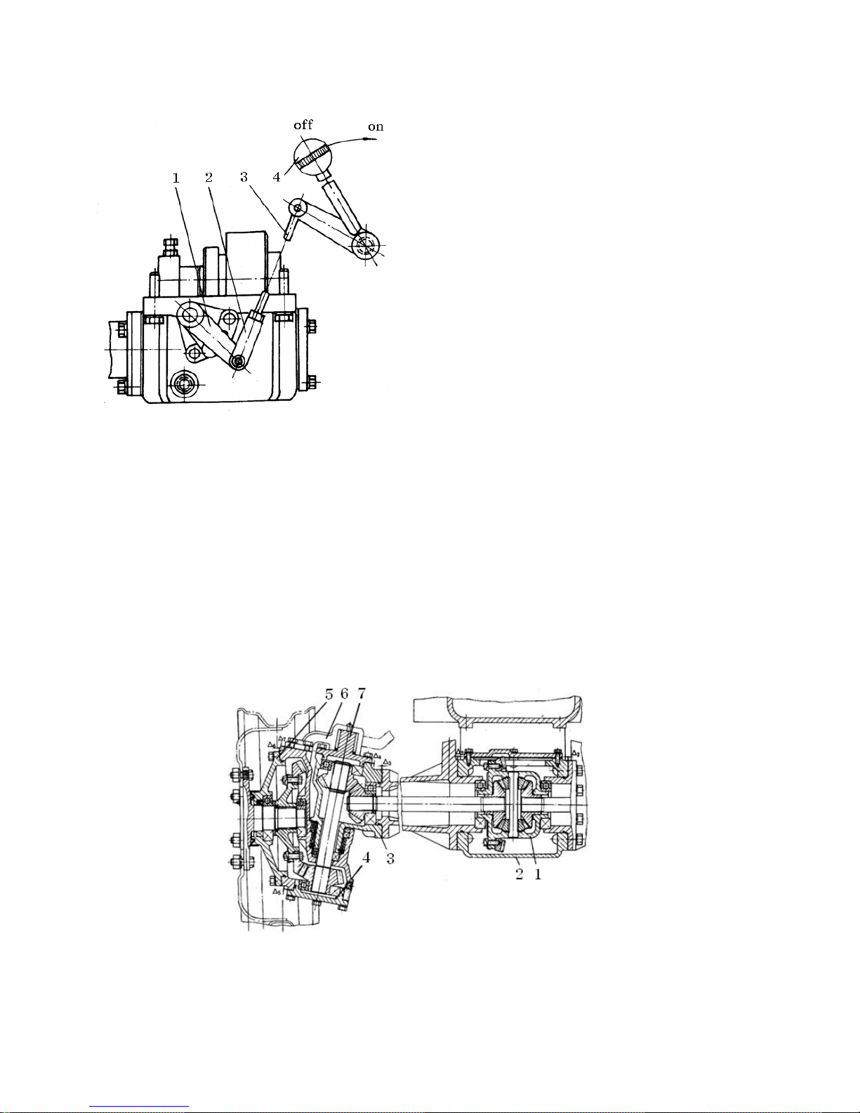
(3) For adjustment of position control cam, please see Fig. 5-13
Put the handles of the position, and draft control in the vertical position. Make the lift arm an angle of
60° with horizontal plane and make the inner lift arm have a clearance of 4mm with the housing.
The position control cam is so turned that the control end of the position control lever push the main
control valve 5.1+0.2mm into its block from its outmost position. Then tighten the belt on the position
control cam.
Fig. 5-13 Adjustment of the cam of position control
1. Position control handle 2. Sector plate for position control 3. Bolt 4. Cam for position control
5. Lift arm 6. Lift housing 7. Inner lift arm 8. Roller 9. Pull spring 10. Position control lever
11. Main control lever
5.10 The Operation Controls of Front Drive Axle
The separating and joint of front drive axle of 4 wheel drive tractors are controlled by the handle under
the left side of drivers seat. See Fig. 5-14 No.4. Put the handle backward, it shuts together the front
drive axle, other wise if takes off them.
43
Page 51
Points to be noticed here: while taking off or
shutting together the front drive axle, first press
down the clutch pedal, then operate the controlling
handle.
Fig. 5-14 Transfer case & control mechanism assy
1. Release rocker
2. Adjustment fork
3. Draw bar
4. Handle control
When the tractor is traveling on the fine road or at high speed, the power of front drive should be cut off,
thus the drive wheels changed to the driven wheels in order to reduce the wearing of tires and prevent
the parasitic power of drive system from producing. On the contrary, you should shut together the front
drive axle to enforce the pulling power and raise efficiency.
5.11 The Structure and Adjustment of Front Drive Axle
(1) The structure and power transmission are shown in Fig. 5-15 & 5-16
Fig. 5-15 Structure diagram of front drive axle
1. Differential assy 2. Central drive case 3. Front axle sleeve 4. Bearing cap, side drive
5. Side drive cover 6. Steering arm 7. Shaft cap, steering arm
44
Page 52
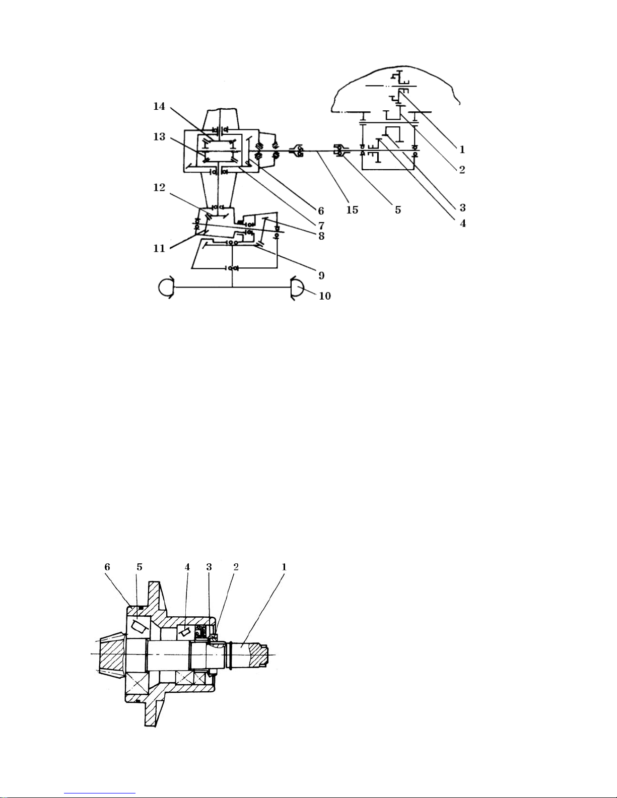
Fig. 5-16 Drive system of front axle
1. Former high-low sliding gear 2/3. Intermediate gear 4. Output slider gear
5. Ball-shape joint sleeve 6. Front center drive gear 6. Front central drive, follower gear
8. Two-stage drive gear , front side drive 9. Two-stage follower gear, front side drive
10. Front wheel 11. Two stage follower gear, front side drive
12. One –stage drive gear , front side drive 13. Planet gear, front axle
14. Front semi-shaft gear 15. Transmission shaft
The power of front drive is passed on firstly to transmission shaft from high-low sliding gear of
transmission housing to intermediate gear and output gear of transfer case, secondly passed on to
the front drive shaft to run the front wheels from the transmission via the spiral bevel gear of front
central drive and two-stage bevel gear.
(2) The bearing preloading of front drive conical gear is shown in Fig. 5-17
Fig. 5-17 Front central drive conical gear assy
1.Front central drive gear
2.Round nut
3.Thrust washer
4.Model 7206 bearing
5.Model 27307 bearing
6.Housing
45
Page 53

When assembling, the rolling bearings model 27307 & model 7206 are needed to enforce some
preload. Since the friction of bearing brings about the axial clearance between the front central drive
gears and makes some alteration, while the clearance surpasses 0.1 mm (measured by clock gauge),
the adjustment is required. Dismount the assy of Fig. 5-17, prize open the thrust washer, turn the
round nut and thus enforce the assy to produce 1~1.5 N*m force moment, at last lock the round nut
with thrust washer.
(3) Check on gear-meshing of front central drive gear pair.
After the set-up of front central drive gear pair, we can observe their gear-meshing conditions and
inspect their gear backlash through the square hole on the upper side of front central drive case to
sure whether they are turning normally or not.
① Check the mark
The fitting meshing marks should be on the central drive gears, not less than 13 mm long and 3.5mm
wide, distributing over the middle side of tooth depth, a little bit nearby the narrow end. The mark
must be under the condition of no-oil, first smear evenly the tooth-face of driven gear with red lead
oil, then run the gear both in positive and negative directions in order to make marks over the both
sides of drive gear.
② Check the gear backlash
The tooth space of the gear pair should be 0.15~0.30mm measured by S-shape fuse or other soft
metal, about 25mm long, put in the unworking faces between the meshed teeth, then turning the
follower gear and fetching out the squeezed fuse, the thinnest degree is just the tooth space. We had
batter measure 3 points around the gear circle.
③ Adjustment
The meshing contact mark and tooth space can be adjusted by way of increasing or decreasing the
thickness of gaskets δ1 (see Fig. 5-19) between the front central drive housing and the front central
drive gear assy, and of gasket group δ1 (see Fig. 5-15) between the front axle sleeve and front
central housing. Point should be noted that group δ2 have two groups between the right side and
the left side, while increasing the left side thickness, decreasing correspondently the right one’s
number at the same time. The details of adjustment, please see “Adjustment of teeth contact
condition for spiral bevel gears” on Chapter 5.
(4) Adjustment of two-stage bevel gear pair, front axle side drive (see Fig. 5-15)
Here is the same way with the above-mentioned to adjust the tooth contact two-stage bevel gear
pair, side drive and clearance by means of increasing and decreasing the thickness of adjusting
gasket δ3 of front one-stage drive gear, side drive; and of adjusting gasket δ4 of bearing cap under
the side drive;again of the adjusting gasket δ5 of the steering rocker bearing cover; and once again
of the gasket δ6 of front side drive housing cover.
46
Page 54
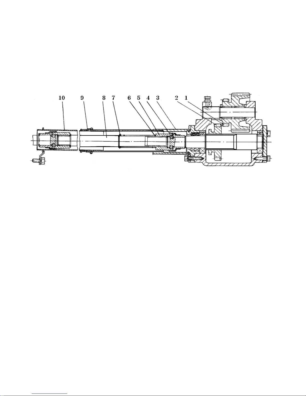
(5) After the fitting of front axle, it requires to run the front central drive gear shaft by hand. If it running
handy and producing equal speeds between the right and the left front drive shafts. It means well-fitting,
otherwise you should fit it again.
5.12 The Structure, installation and Disassembly of Transmission Shaft and Transfer Case
Fig. 5-18 Transfer case and transmission shaft assy
1. Intermediate gear 2. Sliding gear 3. Rear sleeve assy 4. Steel ball 5. Ball joint sleeve
6. Spring 7. Snap ring 8. Transmission shaft 9. Protection shield 10. Front sleeve assy
When disassembling the transmission shaft, first you should take apart the 3 bolts (M8X25) from the
rear sleeve assy, secondly slide forward the rear sleeve assy until the axial snap ring is shown, then
loosen the snap ring and move the ball joint sleeve toward the front central drive housing until it stops
moving forward again. Now you can easily disassembly the drive shaft. Here pay attention to the losses
of steel balls and their mixture with those steel balls which should be installed on the shift fork shaft of
the transmission housing.
5.13 Connection and Adjustment of Front Axle and Its Bracket
The front axle and the bracket are connected by the front & rear supports. When the tractor travels on
the zigzag path, the front axle can swing around to reach ±11° swing angles. Since the frequent
swinging wearing, one of its adjusting ring on the rear support is easy to be worn out, thus you should
give it an instant help by adjusting the bolt on the front support (in clockwise direction and lock the nut.)
The adjusting ring should be changed a new one after using for some time.
47
Page 55
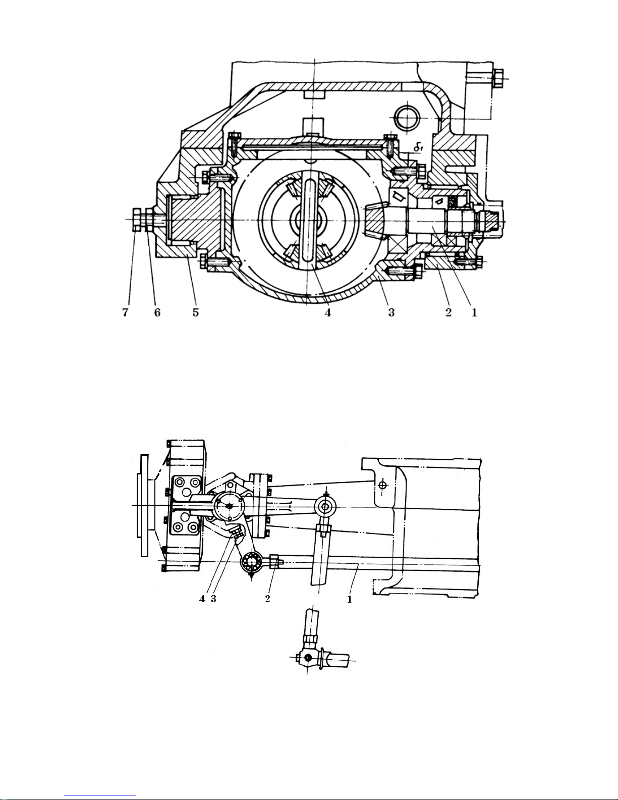
Fig. 5-19 Front central drive ass’y
1. Front central drive gear ass’y 2. Rear support 3. Central drive case 4. Differential ass’y
5.Front support 6. Lock nut 7. Adjusting bolt
5.14 Adjusting of Front Wheel Deflection Angle and Toe-in
1. Cross-rod 2. Lock nut M8X1.5 (L.H) 3. Adjusting bolt 4. Lock nut M10
Fig. 5-20 Steering mechanism assy
48
Page 56

When the tractor steering, the max. deflection angle can be measured according to the number of min.
turning circle radius. If the degree is over big, we can adjust the bolt (see Fig. 5-20 No.3) to decrease it.
The toe-in difference of front wheels should be 3~11 mm reached by adjusting length of the cross-rod
of the steering trapezoid (see Fig. 5-20 No.1)
5.15 Lubricating Points of Front Drive System and Steering system
(1) Gear oil SAE90 (above 0°C temperature) or Gear oil SAE 85W-90 (the same temperature asked)
can be filled into the front central drive, front sleeve and front side drive case until the oil flows out
from the sides of sleeve.
Note : The speed of oil flowing into side drive is a little bit slower than that of other parts. There force
pay attention to the available failure resulting from the oil shortage of other parts.
(2) Present front axle and steering bars have 10 grease nipples together including the front & rear
supports, the two front drive shafts, two steering rocker caps and the rest 4 on the steering connectors,
which shall be added new grease per shift.
49
Page 57

CHAPTER 6 TECHNICAL MAINTENANCE OF TRACTOR
6.1 Technical Maintenance per Shift
The following maintenance work should be made before and after each shift.
(1) Fill fuel, lubricating oil and grease according to the instructions of oil chart and table.
(2) Check the water lever of the radiator and replenish it if necessary.
(3) Inspect whether there is dirt or water in the fuel sediment cup. Clean it and expel the air from the
fuel line.
(4) Inspect and remove any leakage of oil, water and air from the fittings.
(5) Check and tighten fasteners of all fittings.
(6) Check the tire and its inflation pressure.
(7) Check and bring along all the necessary tools.
(8) Clean the dust on the surface of the batteries and the rust of the battery terminals. Check the
electrolyte lever in the batteries (18 ~ 23 mm above the separator), add distilled water if it is
insufficient. Check should be done every 60 hours when working in winter or in wet area.
6.2 1st Technical Maintenance
The following maintenance work should be made after every 100 hours of working.
(1) Complete all the maintenance items in technical maintenance per shift.
(2) Change the oil in the oil sump.
(3) Wash the fuel tank and its inlet screen.
(4) Wash the oil filter and change the element if necessary.
(5) Wash the cleaner and change the oil or clean the dust of air cleaner element.
(6) Check the tension of the fan belt by pressing with thumb nearly midway on its straight portion,
if the belt deflects about 15 mm the tension is correct.
(7) Turn off the plugs on each side of transmission brakes and the plug under the flywheel housing.
Check and drain any oil that may leak out.
50
Page 58

6.3 2nd Technical Maintenance
The following maintenance work should be made after every 500 hours of working.
(1) Carry out all the maintenance items in technical maintenance per shift and primary technical
maintenance.
(2) Wash the oil sump, inlet screen and strainer.
(3) Check the injection pressure and the condition of atomization. Clean and readjust the nozzles
if necessary.
(4) Check the working of the injection pump and its advanced angle. Readjust it if necessary.
(5) Wash the fuel filter, change the element if necessary. Expel the air from fuel lines after
reassembling.
(6) Check and readjust the valve clearance and the free-turning clearance of steering wheel.
(7) Check and readjust the free travel and working travel of the brake pedal and the clutch pedal.
(8) Check the clearance of front wheel bearing. Readjust it and adjust front toe-in if necessary.
(9) Wash the screen in hydraulic system.
6.4 3rd Technical Maintenance
After every 1000 hours of working the following maintenance work should be made.
(1) Carry out all the maintenance items in technical maintenance per shift, technical maintenance of
primary and secondary.
(2) Clean the dust and dirt on the tractor, the dust between radiator pipes and the scale in the water
pump.
(3) Dismount the engine. Clean the carbon deposit on the cylinder head. Check the valve seats
(reamer the valve seat and grind the valve if necessary). Clean the carbon deposit on the piston.
Check the piston ring end gap, the wear-out of cylinder sleeve, the corrosion of alloy surface of
connecting-rod bearing and crankshaft bearing and change the bearing if necessary.
(4) Wash the main oil passage in cylinder block. Check wear-out of the end cover of oil pump and the
working of the pressure-limiting valve on the oil filter cover. Readjust them if necessary.
(5) Change the lubricant in transmission housing and final drive housing and clean the magnet in
transmission housing.
(6) Renew the grease in the front wheel hub.
(7) Check the Specific gravity of battery electrolyte and discharge condition. Correct the specific
gravity of electrolyte or recharge if necessary.
51
Page 59

(8) Inspect the voltage regulator. Readjust it if necessary.
(9) Inspect the components and parts of the alternator and the starter, especially the blush and silicon
rectifier. Repair or change them if necessary.
(10) Check the grease in steering gear and renew it if necessary.
(11) After reassembling of the tractor, a short-time running-in is necessary to inspect the action of
every part.
6.5 Special Maintenance in Winter
Attention should be paid to the following items when atmospheric temperature is below 5°C
(1) Starting engine is forbidden if there is no water in the cooling system.
(2) The coolant temperature should not be below 60°C when the tractor begins to work.
(3) For long stay the water in the cooling system should be drained out (the water temperature should
be dropped down to 50~55°C before draining), so should the oil in the oil sump.
(4) Under extremely low atmospheric temperature anti freezing coolant with lower freezing point
should be used, which consists of 94% alcohol and water, the proportion of volume being 2.5
(alcohol):5.5(water).
(5) The tractor should stay inside room.
52
Page 60

CHAPTER 7 TROUBLE SHOOTING
7.1 Engine
Engine trouble and possible cause and possible remedy are shown in Engine Operation Manual.
7.2 Chassis
1. Clutch
Trouble and possible cause Possible remedy
A. Clutch slips
(1) Friction disk stained with oil
(2) Pressing spring weakened or broken
(3) Short or no pedal free travel
(4) Driven disk curved, uneven wear-out or
excessively worm-out.
(5) Tree-release-lever end forces not in the same
plane.
B. Clutch disengaged Incompletely, hand to
engage or engaged with sound and tractor
started off with shake.
(1) Pedal working travel too short and excessive
free travel.
(2) Driven disk curved excessively.
(3) Three-release-lever end faces not in the
(1) Flush friction disk with gasoline and remove
oil leakage
(2) Replace spring
(3) Readjust pedal free travel according to the
specification.
(4)Rectify or replace driven disk
(5) Adjust the release lever end faces
(1) Adjust pedal working travel and free travel
(2) Rectify or replace driven disk
(3) Adjust the release lever end faces
same plane.
(4) Friction disk broken
(5) Friction disk spline too tight
C. Vibration and noise in clutch
(1) Release lever pressure spring broken
(2) Release bearings lubrication insufficient or
damaged
(3) Splined hole of driven disk or clutch spilned
shaft worn out
(4) Clutch front bearing damaged
(4) Replace friction disk
(5) Repair spline
(1) Replace spring
(2) Lubricate or replace release bearings
(3) Replace worn out parts
(4) Replace front bearing
53
Page 61

2. Brake
Trouble and possible cause Possible remedy
A. Ineffective brake
(1) The shifting block broken.
(2) Friction disk is excessively worn-out.
(3) The steel ball is distorted
(4) Excessive pedal free travel.
B. Two wheels can not be braked simultaneously
(1) Right and left pedal travel different.
(2) One pressure disk is excessively worn-out
C. Brake disengaged incompletely and overheated
(1) The return spring weakened
(2) Brake pedals will not return
(3) Short pedal free travel
3. Transmission box
Trouble and possible cause Possible remedy
(1) Replace shifting block
(2) Exchange friction disk
(3) Replace steel ball
(4) Readjust pedal free travel
(1) Readjust pedal travel
(2) Replace pressure disk
(1) Replace spring
(2) Check return spring for damage, shaft
for being gripped and remove them.
(3) Readjust pedal free travel
A. Abnormal sound in transmission box
(1) Transmission box bearing or rolling needle
excessively worn out or damaged.
(2) Abnormal meshing of main drive gears.
(3) Shaft splines and gear splined hole worn out
B. Gear engagement out of order
(1) For excessively worn out or deformed
(2) For shaft locking spring weakened
(3) Tooth profile or spline excessively worn out
C. Transmission box overheated
(1) Short clearance of bearing or gears
(2) Insufficient or excessive lubricating oil
(3) Deteriorated lubricating oil
(1) Check and replace worn out parts.
(2) Examine meshing traces and backlash and
adjust them in accordance with regulations
(3) Replace worn out parts
(1) Replace fork
(2) Replace spring
(3) Replace worn out parts
(1) Readjust the clearance
(2) Add or drain out lubricating oil to specified
level
(3) Replace lubricating oil
54
Page 62

4. Traction devices and steering system
Trouble and possible cause Possible remedy
A. Front wheel swing
(1) Excessive clearance of front wheel bearing or
kingpin sleeve worn out excessively
(2) Wrongly adjusted toe-in
(3) Ball pin and ball pin seat worn out excessively
(4) Pitman arm and ball pin fixing nut loose
B. Early worn out of front wheel tires
(1) Wrongly adjusted toe-in
(2) Front wheel pressure insufficient
C. Excessive steering wheel free travel
(1) Ball pin and ball pin seat won out excessively
5. Hydraulic system
Trouble and possible cause Possible remedy
A. Lack of lifting force or lifter will not lift
(1) Low oil level or improper type of oil
(2) Clogged oil inflow trainer
(3) Air in hydraulic system
(4) Oil pump seriously worn out, leaking serious
(5) Lower valve is open
(6) Main control valve or return valve worn out
seriously
(7) Ineffective safety valve
(8) Cylinder leaking seriously
(9) Leakage at distributor seal rings
(1) Adjust bearing clearance and replace
kingpin sleeve
(2) Readjust toe-in
(3) Replace ball pin and ball pin seat
(4) Check and tighten the nut
(1) Readjust toe-in
(2) Inflate tire to specified pressure
(1) Replace ball pin or ball pin seat
(2) Check and tighten the nut
(1) Add proper oil to specified level
(2) Flush the strainer
(3) Drain system and tighten contactor or
replace seal ring
(4) Replace oil pump seal ring
(5) Dismount and clean
(6) Replace worn out parts
(7) Readjust or repair safety valve
(8) Replace seal ring or replace worn out parts
if necessary
(9) Replace seal rings
B. Implement lifted with shake
(1) Lower valve is close
(2) Closed lowering speed regulating valve or shut-
Off valve
C.Implement lifted with shake
(1) Check valve worn out and closed incompletely
(2) Leakage at seal rings of the distributor and
Cylinder
(1) Dismount and clean
(2) Open the valve
(1) Repair or replace check valve
(2) Find out the position of leakage and
replace worn out seal rings
55
Page 63

7.3 Electrical System
1. Battery
Trouble and possible cause Possible remedy
A. Frequently insufficient electric power
(1) Low electrolyte level
(2) Short circuit plates
(3) Plates sulphurized
(4) Defective generator or regulator
(5) Defective wire contraction
B. Battery overheated
(1) Short circuit of plates
(2) High changing electric current
C. Charge capacity of battery distinctively reduces
(1) Plates sulphurized
(2) Sulphuric acid not pure
(3) Plate curved, active material peeled off and spacer
damaged to cause short circuit
2.Generator
(1) Add to specified level
(2) Clean deposit, change electrolyte and
replace spacers or plates
(3) Charge repeatedly to remove sulphur
(4) Repair generator or regulator
(5) Check wire contraction to remove trouble
(1) Clean deposit, change electrolyte and
replace spacers or plates
(2) Adjust regulator
(1) Change repeatedly to remove sulphur
(2) Use proper electrolyte
(3) Replace plate
Trouble and possible cause Possible remedy
A. Generator will not work
(1) Rectifying unit damaged
(2) Block brush gripped and no contraction with
collector ring
(3) Stator winding or rotator winding broken circuit,
short circuit or negative pole and terminals
defective insulation.
B. Lack of generator power
(1) Loose generator belt
(2) Some rectifying unit damaged
(3) Defective block brushes and collector ring
stained with oil.
(4) Part of rotator winding or stator winding short
circuit.
56
(1) Adjust belt tension or replace belt
(2) Repair or replace rotator winding or stator
winding.
(3) Repair or replace block blush spring
(1) Remount the generator correctly
(2) Replace generator bearings
(3) Repair
(4) Repair
Page 64

Trouble and possible cause Possible remedy
C. Unsteady generator electric current
(1) Loosened generator belt
(2) Rotator winding or stator winding near short
circuit or broken circuit.
(3) Low pressure of block brush spring and defective
contraction of block brush
(4) Loose terminals
D. Abnormal sound in generator
(1) Generator wrongly mounted
(2) Generator bearing damaged
(3) Rotator hitting stator or other parts
2.Generator
Trouble and possible cause Possible remedy
A. Starter will not work
(1) Connecting wire broken of defective contraction
of connecting wire and switch contacts
(2) Fuse blown
(1) Adjust belt tension or replace belt
(2) Repair or replace rotator winding or stator
Winding
(3) Repair or replace block brush spring
(4) Repair
(1) Remount the generator correctly
(2) Replace generator bearings
(3) Repair
(1) Weld or replace connecting wire, clean the
oil on contacts and tighten the nuts on contacts
(2) Replace fuse
(3) Battery no electricity or low battery voltage
(4) No contraction of block brushes with direction
exchangers
(5) Short circuit of starter
B. Starter can run but cannot start engine
(1) Shaft bushing excessively worn out and rotator
frictioning with magnet
(2) Defective contraction of block bushes with
direction exchangers.
(3) Direction exchanger surface burnt of stained
with oil
(4) Welding of wire connecting armature and
direction exchanger broken
(5) Defective contraction of wire
(6) Magnetic switch contacts sintered
(7) Battery insufficiently charged
(8) Low atmosphere temperature
(3) Charge battery
(4) Change block brush, adjust brush spring
pressure
(5) Remove short circuit
(1) Replace shaft bushing
(2) Flush direction exchanger surface, correct
brush contacting surface and adjust spring
pressure
(3) Grind direction exchanger surface, remove
oil on direction exchanger surface
(4) Re-weld
(5) Tighten nuts
(6) Repair magnetic switch contacts
(7) Charge battery
(8) Use starting methods at low atmosphere
Temperature
57
Page 65
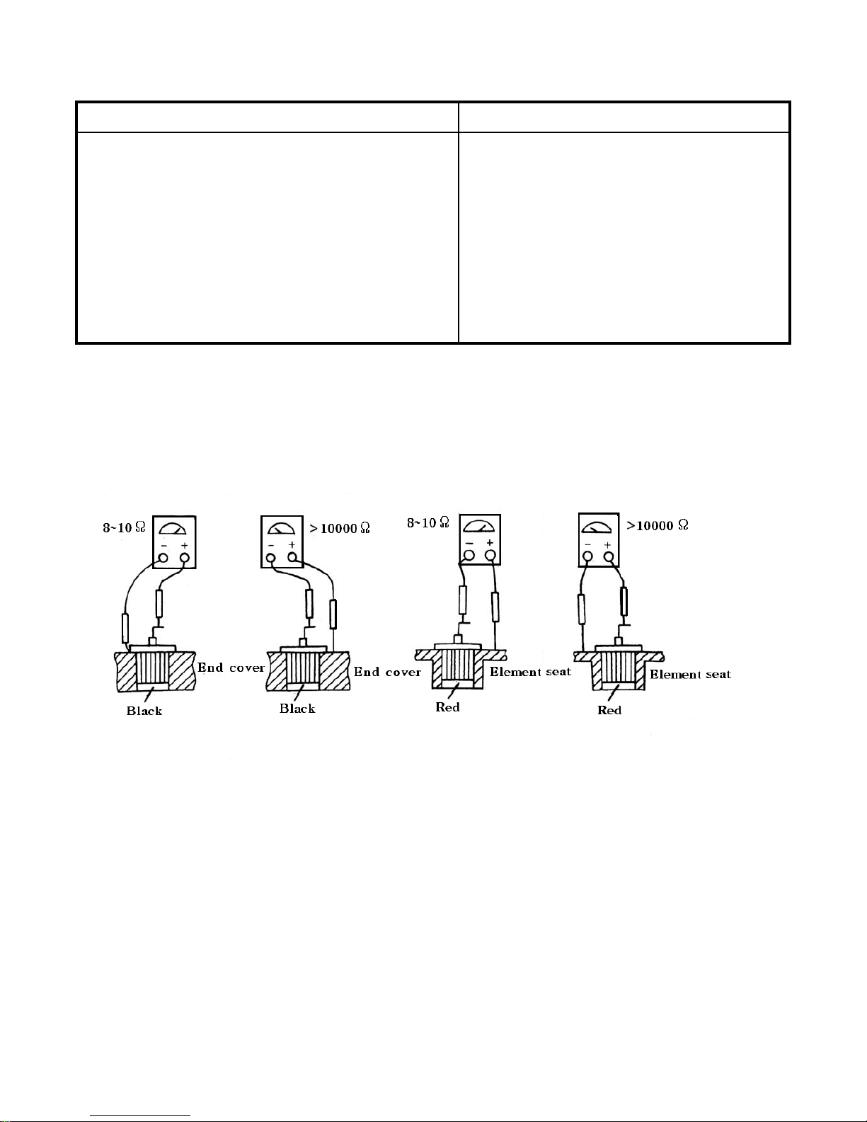
Trouble and possible cause Possible remedy
C. Starter continues running after engine has
been Started.
(1) Magnetic switch contacts sintered
(2) Incorrect adjustment of the travel of magnetic
(1) Repair magnetic switch contacts
(2) Readjust the travel
switch iron core
D. Starter begins to run and hits the end face of
Readjust magnetic switch travel
ring gear before starter gear has been meshed
Short magnetic switch travel
Appendix : Check of silicon rectifiers
When checking silicon rectifiers take off the plate connecting generator winding with rectifiers and
measure rectifiers one by one with an avometer of high inner resistance in RX1 step (Fig. 7-1)
First measure the rectifiers on the rear end cover. Contact “-” measure stick of avometer with end cover,
and “+” measure stick with rectifier wire, the reading on the avometer should be 8~10Ω. Then contact
“-” measure stick with rectifier wire and “+“ measure stick with end cover, the reading on the avometer
should be over 10000Ω. The electrode of the three rectifiers on the rectifier panel is opposite to that of
the three rectifiers on the end cover. The result of measurement is also apposite. If the positive
resistance is below 1Ω, this means the result are of short circuit. If the negative resistance is hundreds
of kΩ, this means the rectifiers are of open circuit.
Fig. 7-1 Check silicon rectifiers
58
Page 66

CHAPTER 8 APPENDICES
8.1 Tightening Torque of important Bolts and Nuts
Table 8-1 Tightening torque of important bolts and nuts
Parts to be connected Tightening torque, (kg m)
Cylinder head and cylinder block 12~14
Connecting rod cap and connecting rod 10~12
Cover of main bearing and cylinder block 14~16
Flywheel and crankshaft 10~12
Bracket and engine 9~12
Front bush of 2nd shaft and transmission housing 4~6
Inner bearing cover of drive shaft and final drive housing 4~5
Intermediate housing and flywheel housing 3.5~5
Intermediate housing and transmission housing 6~8
Rear axle sleeve and transmission housing 6~8
Rear axle sleeve and final drive housing 6~8
Front axle sleeve and front axle arm 6~8
Lifter housing and transmission housing 2~3
Steering-gear case and intermediate housing 2~3
Front wheel spoke and front wheel hub 12~14
Rear wheel spoke and drive shaft 12~14
Rear wheel spoke and rear wheel rim 7~9
Ballast weight on rear wheels 3.5~5
59
Page 67
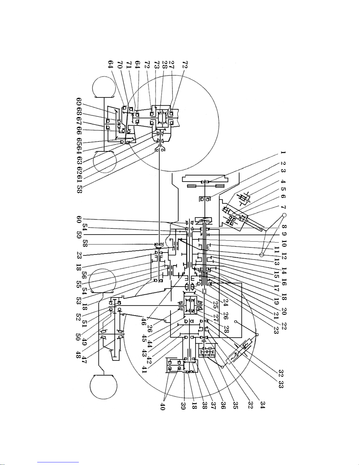
8.2 Diagram of Transmission system
For transmission system diagram, please see Fig. 8-1 and Table 8-2 and 8-3.
Fig. 8-1 Transmission system diagram
60
Page 68
Table 8-2 Bearing No. and needles size of the tractor
Item Bearing No. Item Bearing No. Item Bearing No. Item Bearing No.
1 60203 22 208 41 50207 60 27305
2 688908 23 2.5X16X90 43 305 61 7207
3 977907K 24 92608 or 3608 47 7307 62 27307
4 922205 26 7210 48 7212 64 46208
6 776701 51 50209 66 8206
7 977907 32 205(305) 52 209 67 46209
8 907 37 210 59 3X24X130 68 207
18 106 40 306 58 Steel ball φ8X12 72 46210
Table 8-3 Gear teeth and modulus of the tractor
Item Gear
teeth X m
Item Gear
teeth X m
Item Gear
teeth X m
Item Gear
teeth X m
5 1X4.6685 20 42X3 42 39X3 65 15X5
9 18X3 21 19X3 44 47X3 69 44X5
10 32X3 25 14X4.2(10X5.2) 45 53X4.2(43X5.2) 70 16X5
11 28X3 27 20X4.3 46 22X3 71 14X5
12 25X3 28 12X4.3 49 77X4 [ 74X 4 ] 73 44X4.1
13 39X3 33 14X3 50 13X4 [ 16X 4 ]
14 22X3 34 22X3 53 30X3
15 34X3 35 10X3 54 43X3
16 26X3 36 10X3 55 21X3 (20X3)
17 39X3 38 26X3.5 56 28X3 (29X3)
19 22X3 39 18X3.5 63 9X4.1
61
Page 69
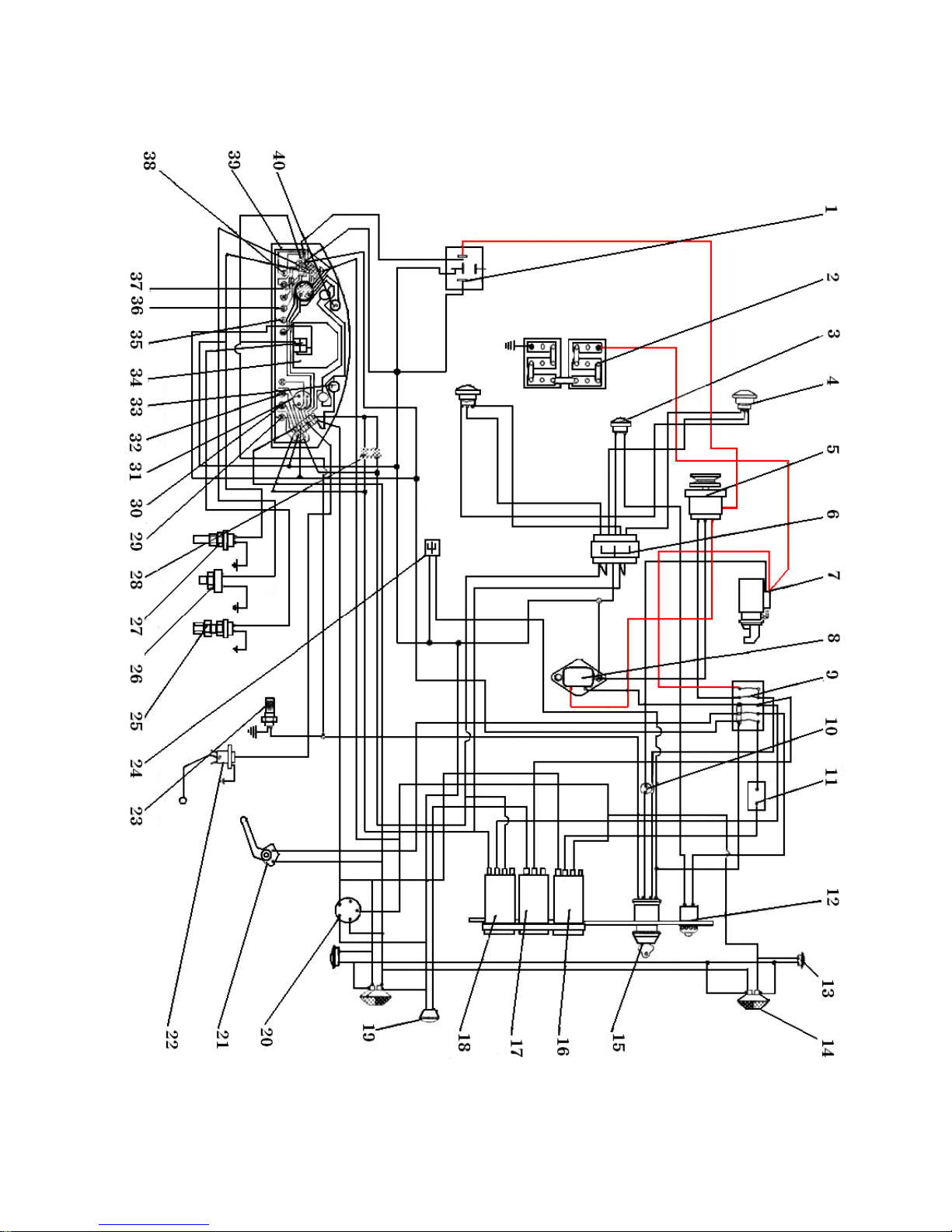
8.3 Electrical system wiring diagram
62
Page 70

Fig. 8-2 Electrical system wiring diagram
1. Charge relay 2. Battery 3. Horn 4. Front head lamp 5. Generator 6. 8-plugs socket
7. Starting motor 8. Regulator 9. Fuse box 10. Safety switch 11. Blinker 12. Horn button
13. Direction light 14. Direction brake lamp 15. Electricity lock 16. Direction light switch
17. Tai l lamp switch 18. Front head lamp switch (Upper beam, lower beam) 19. Tail lamp
20. 5-plugs socket 21. Brake switch 22. Oil sensor 23. Preheating plug
24. Engine checking electric plug 25. Rated speed sensor 26. Oil pressure sensor
27. Water temperature sensor 28. Unidirectional electric capacity 29. Front head Pilot lamp
30. Tail pilot lamp 31. Oil gauge 32. Brake pilot lamp 33. Left steering pilot lamp
34. Tachometer/hour meter 35. Oil pressure pilot lamp 36. Change pilot lamp
37. Water temperature gauge 38. Preheating pilot lamp
39. Back of wiring diagram with cluster panel 40. Right steering pilot lamp
63
Page 71
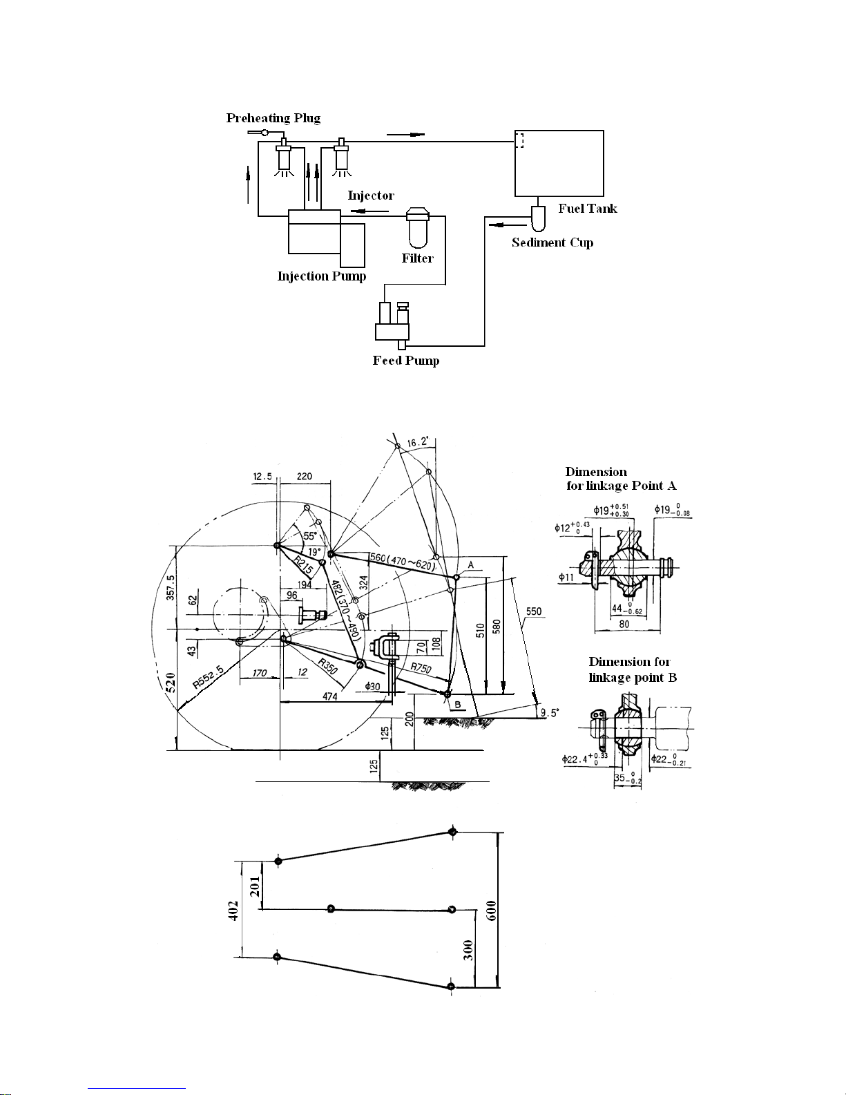
8.4 Fuel System Diagram
Fig. 8-3 Fuel system diagram
8.5 Hitch System Dimensions
Fig. 8-6 Optional Accessories
64
Page 72
Table 8-5 Optional accessories
Item Description Quantity Application
1
2
3
4
5
Rear wheel ballast
Air brake device
Roll-over protective structure
Paddy wheel of ground-grip tire
Roof
4
1 Set
1 Set
2
1 Set
Dry field operation or transportation
For trailer
For safety
Paddy field operation
Sun protection
65
Page 73

ET 350 ECONO 4WD TRACTOR
ENGINE
PARTS CATALOGUE
66
Page 74
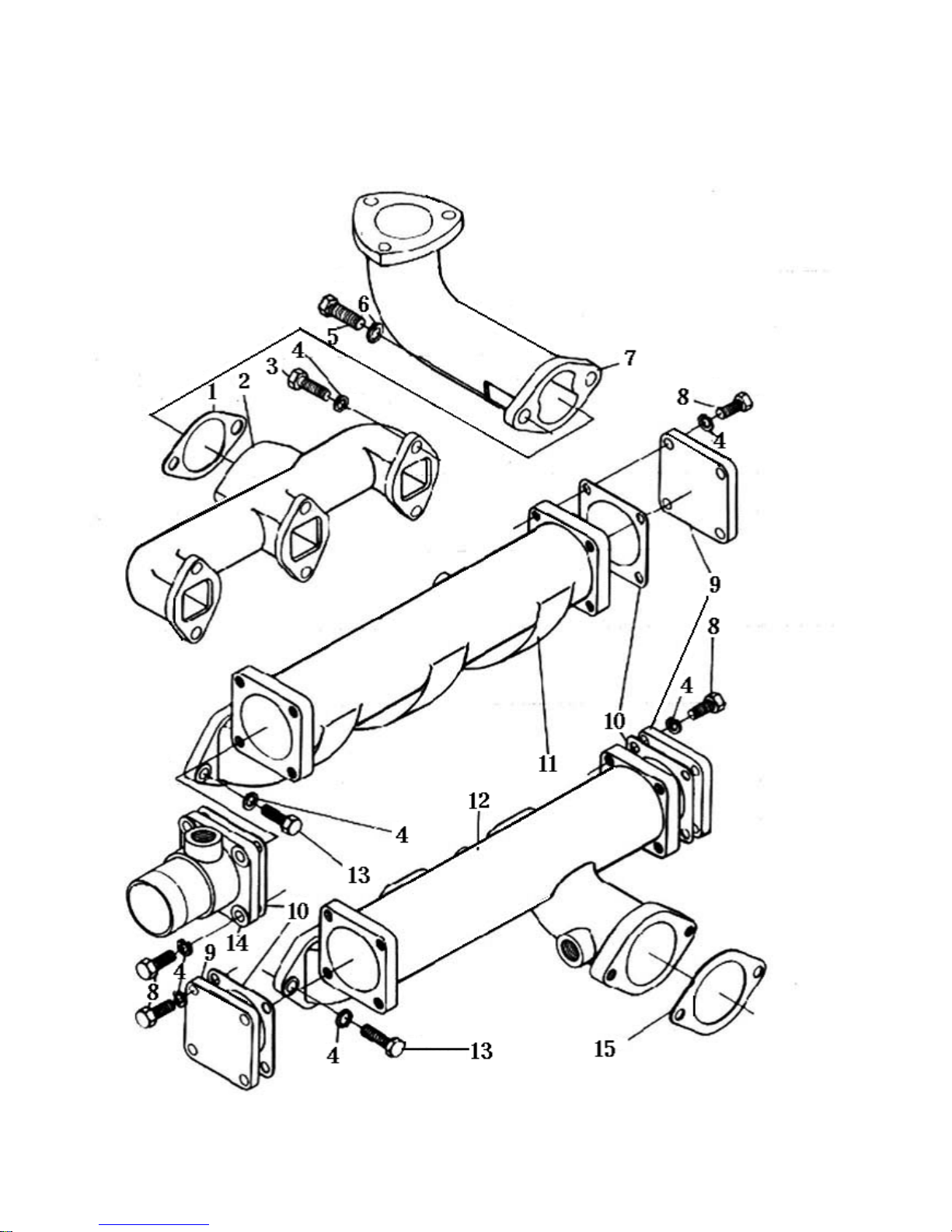
1. INTAKE AND EXHAUST PIPE ASSEMBLY
67
Page 75

1. INTAKE AND EXHAUST PIPE ASSEMBLY
No. Code Name QTY
1
2
3
4
5
6
7
8
9
10
11
12
13
14
TY295I.10.2-3
TY395I.10-2
GB5783-86
GB93-87
GB5783-86
GB93-87
TY395I.10-2-4EPA
GB5783-86
TY395I.10-4
TY395I.10-5
TY395IT.10.1-1NBa
TY395IT.10-1NBa
GB5783-86
TY395I.10.1-2NBa
Exhaust pipe gasket
Exhaust connecting pipe
Stud bolt M8 X 35
Was he r 8
Stud bolt M10 X 22
Was he r 1 0
Exhaust pipe
Stud bolt M8 X 20
Intake pipe flange
Intake pipe flange gasket
Intake pipe (30Ps)
Intake pipe (35Ps)
Stud bolt M8 X 22
Intake connecting pipe
1
1
6
12
2
2
1
4
2
2
1
1
6
1
15
Intake pipe elbow gasket
1
68
Page 76
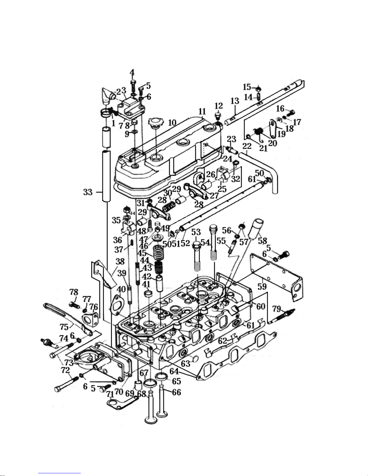
2. CYLINDER HEAD ASSEMBLY
69
Page 77

2. CYLINDER HEAD ASSEMBLY
No. Code Name QTY
1
2
3
4
5
6
7
8
9
10
11
12
13
14
TY395IT.1.2-10NB
TY395IT1.2-12NB
GB5783-86
GB5783-86
GB 859-87
TY395IT.1.2-11NB
GB923-88
GB848-85
TY395.1.2-4
TY395.1.2-1
TY395.1.2-6
TY395.1.2-2
TY395.1.2-3
Hoop assembly
Ventilate pipe fittings
Ventilate room blind flange
Bolt M8 X 40
Bolt M8 X 20
Was he r 8
Ventilate board gasket , plug
Nut M8
Was he r 8
Adjusting hole cover
Cylinder head bonnet
Locating screw
Decompression shaft
Reduce pressure screw
1
1
1
2
2
24
1
4
4
3
1
1
1
3
15
16
17
18
19
20
21
22
23
24
25
26
27
28
GB6170-86
GB5783-86
BN859-87
TY395.1.2-8
TY395.1.2-2
TY295I.1.3-4
GB3452.1-2
SG79-84
TY295I.1-25
TY395.1-1
TY295.1-10
TY295.1-13
TY295I.1.4a
Ty295.1-23
Nut M6
Bolt M6 X 16
Was he r 6
Was he r
Decompression handle
Spring , twisting force
O ring (rubber seal 11.8 X 2.65)
Pipe 8 X 0.6 X 190
Wind pipe(Connector)
Cylinder head bonnet gasket
Rockshaft carrier II
Rockshaft bush I
Respirator becomes always
Valve rocker arm
3
1
1
1
1
1
1
1
1
1
3
2
1
6
70
Page 78

2. CYLINDER HEAD ASSEMBLY
No. Code Name QTY
29
30
31
32
33
34
35
36
37
38
39
40
41
42
S195-03005
TY295.1-14
GB6170-86
TY495.1.24
TY284IT.1.2-13NB
GB6170-86
GB859-87
TY295.1-11
TY295.1-22
TY395IT.1.2-14NB
TY495.1-12
TY295.1-20
TY295.1.1-5
S195-03011
Rocker arm bush
Rockshaft spring
Nut M8
Rockshaft carrier washer
Stick pipe
Nut M12
Was he r 1 2
Rockshaft carrier II
Screw
Stick pipe location board
The carrier of rockshaft fires screw
Exhaust pipe gasket
Water plug Φ 28
Valve guide stem
6
3
4
3
1
4
3
1
1
1
4
3
3
6
43
44
45
46
47
48
49
50
51
52
53
54
55
56
GB899-88
TY295.1-3
TY295.1-4
S195-03008
S195-03007
S195-03006-1
TY495.1-23
GB894.1-86
TY295.1.2-2
TY395.1.3.2-1
TY395I.1-5EPA
TY295.1-6
GB899-88
GB859-87
Bolt AM8 X 80
Valve spring (Inner)
Valve spring (Outer)
Spring seat cover
Valve collects
Valve clearance adjusting screw
Valve cap
Check ring 16
Rockshaft plug
Rockshaft
Cylinder head bolt I
Cylinder head bolt II
Bolt AM8 X 50
Was he r 8
4
6
6
6
12
6
6
2
2
1
3
11
6
6
71
Page 79

2. CYLINDER HEAD ASSEMBLY
No. Code Name QTY
57
58
59
60
61
62
63
64
65
66
67
68
69
70
GB6170-86
TY395I.1.16EPA
TY295.1-8
TY295.1-7
TY395.I.1.1-1EPA
TY395I.1-3
TY295.1.1-4
TY295.1-9
TY295.1-.
TY295.1-2
TY295.1.1-2
TY295.1-1
TY495.2.1-8
TY295.1-19
Nut M8
Injection bush
Rear cover plate
Rear cover plate gasket
Cylinder head
Wring board
Stopper
Intake pipe gasket
Exhaust valve seat
Exhaust valve
Intake valve seat
Intake valve
Front cover plate gasket
Bolt M8 X 80
6
3
1
1
1
1
3
1
3
3
3
3
3
1
71
72
73
74
75
76
77
78
79
80
81
82
83
84
TY395IT.1.2-15NB
GB5782-86
TY395I.2-6EPA
NJ-12DI
TY295.2.20a
TY295.1-21
GB859-87
GB5783-86
PF68S19
TY395I.1.1-7EPA
TY395I.1.1-8EPA
TY395I.1-30EPA
TY395I.1-31EPA
TY395I.1-32EPA
Front cover plate
Water temperature induction plug
Belt tightening pulley bracket
Hoisting ring
Was he r 1 0
Bolt M10 X 20
Injection
Fuel injector locator
TY395EPA series
TY385EPA series
TY385EPA series
1
2
1
1
1
1
2
2
3
3
3
1
1
1
72
Page 80
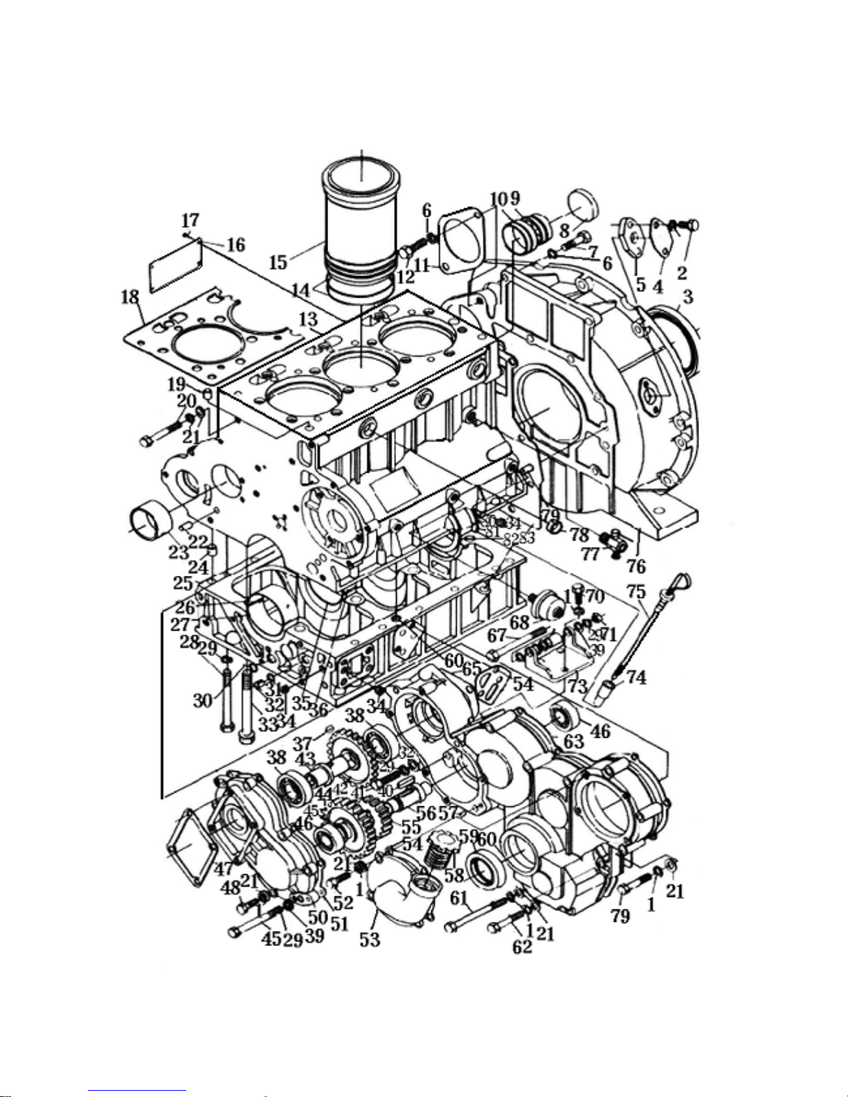
3. CYLINDER BLOCK ASSEMBLY
73
Page 81

3. CYLINDER BLOCK ASSEMBLY
No. Code Name QTY
1
2
3
4
5
6
7
8
9
10
11
12
13
14
GB859-87
GB5783-86
GB2600-80
TY395I.2-17
TY395I.2-18
GB859-87
GB5783-86
TY295.2.1-11
TY295.2.1-3
TY295.2.1-2
TY295.2-23
GB5783-86
TY395.2.1-1
TY295.2-8
Was he r 8
Bolt M8 X 16
Oil seal PG 100 X 130 X 12
Cover of observation hole
Gasket of observation hole
Was he r 1 2
Bolt M12 X24
Plug
Rear camshaft bush
Inside camshaft bush
Start generator gasket
Bolt M12 X 35
Cylinder block
Water sealing ring
32
2
1
1
1
12
10
1
1
1
1
2
1
6
15
16
17
18
19
20
21
22
23
24
25
26
27
28
TY395I.2-7EPA
TY395I-2-29
GB867-86
TY395.2-6EPA
TY295.2.1-10
GB5782-86
GB859-87
TY295.2.1-5
TY295.2.1-2
TY395IT.2.1-10NB
TY395.2.1-3
TY295.2-4
TY295.2-5
GB5782-86
Cylinder sleeve
Name plate
Blind Rivet (2 X 6)
Cylinder head gasket
Pin
Bolt M 10 X 110
Was he r 8
Pin
Front camshaft bush
Pin
Main bearing cap
Front and rear main bearing half shelf(upper)
Front and rear main bearing half shelf(lower)
Bolt M10 X 110
3
1
4
1
2
2
1
1
1
2
2
8
74
Page 82

3. CYLINDER BLOCK ASSEMBLY
No. Code Name QTY
29
30
31
32
33
34
35
36
37
38
39
40
41
42
GB859-87
GB3452.1-82
GB3452.1-82
TY495.2.1-8
TY295.2.1-8
TY495.2.1-8
TY295.2-6
TY295.2-7
GB1096-79
GB296-82
GB93-87
GB1096-79
GB5782-86
TY295IT.16-4a
Was he r 1 0
O ring 11.8 X 1.8
O ring 15 X 1.8
Elastic sleeve
Main bearing cap
Oil gallery plug
Middle main bearing half shelf(upper)
Middle main bearing half shelf(lower)
Key(10 X 16)
Ball bearing 203
Was he r10
Key(10 X 34)
Bolt M10 X 110
Hydraulic pump gear II
1
1
3
8
6
4
4
1
1
1
1
43
44
45
46
47
48
49
50
51
52
53
54
55
56
TY295.2-11
TY295IT.2-37b
GB874-1-86
GB276-82
TY295.2-13
GB5782-86
GB5782-86
TY295.2-12
TY295.2-13
GB5782-86
TY395.2-5
TY395.2-4
TY295IT.16-2a
TY295IT.2-32a
Transmission shaft ,lift pump
Hydraulic pump gear I
Circlip 30
Ball bearing 106
Gasket ,lift pump
Bolt M8 X 30
Bolt M10 X 95
Cover ,lift pump
Gasket,lift pump
Bolt M10 X 30
Cover , air pump hole
Gasket ,air pump hole
Transfer axle gear
Transfer axle
1
1
1
1
1
12
2
1
1
2
1
1
1
1
75
Page 83

3. CYLINDER BLOCK ASSEMBLY
No. Code Name QTY
57
58
59
60
61
62
63
64
65
66
67
68
69
70
GB119-86
TY295IT.2.3
JB2600-80
TY395.2-3
GB5782-86
GB5783-86
TY295.2-9
TY295.2-22
TY295IT.16-12a
GB3452.1-2
TY295IT.2-35b
CY-412
TY295I.2-27
GB5782-86
Pin 5 X 10
Oil filler assembly
Oil seal PG 45 X 65 X 12
Gear case cover
Bolt M8 X 75
Bolt M8 X 30
Gear case gasket
Oil clarifier gasket
13.2 X 2.65 Type O rubber
Seal ring 13.2 X 2.65
Alternator support body
Oil pressure sensor
Electrical generator’s pipe
Bolt M10 X 60
2
1
1
1
2
2
1
1
1
1
1
1
1
3
71
72
73
74
75
76
77
78
79
80
81
82
83
GB859-87
GB5782-86
TY295.2-19
TY295I.2.2.2
TY295I.2.2.1
TY295.2-1
S195-01300A
TY295.2.1-4
TY295.2.1-10
TY295.2-3
TY495.2-26
TY495.2-25
TY395.2-2
Was he r 1 0
Bolt M8 X 55
Alternator support body
Oil level gauge connect
Oil lever dipstick
Flywheel box
Water-draining cock
Oil stopper
Pin 10
Upper thrust piece ,crankshaft
Lower thrust piece ,crankshaft(outer)
Lower thrust piece,crankshaft(inner)
Flywheel box gasket
3
6
1
1
1
1
1
7
2
2
1
1
1
76
Page 84
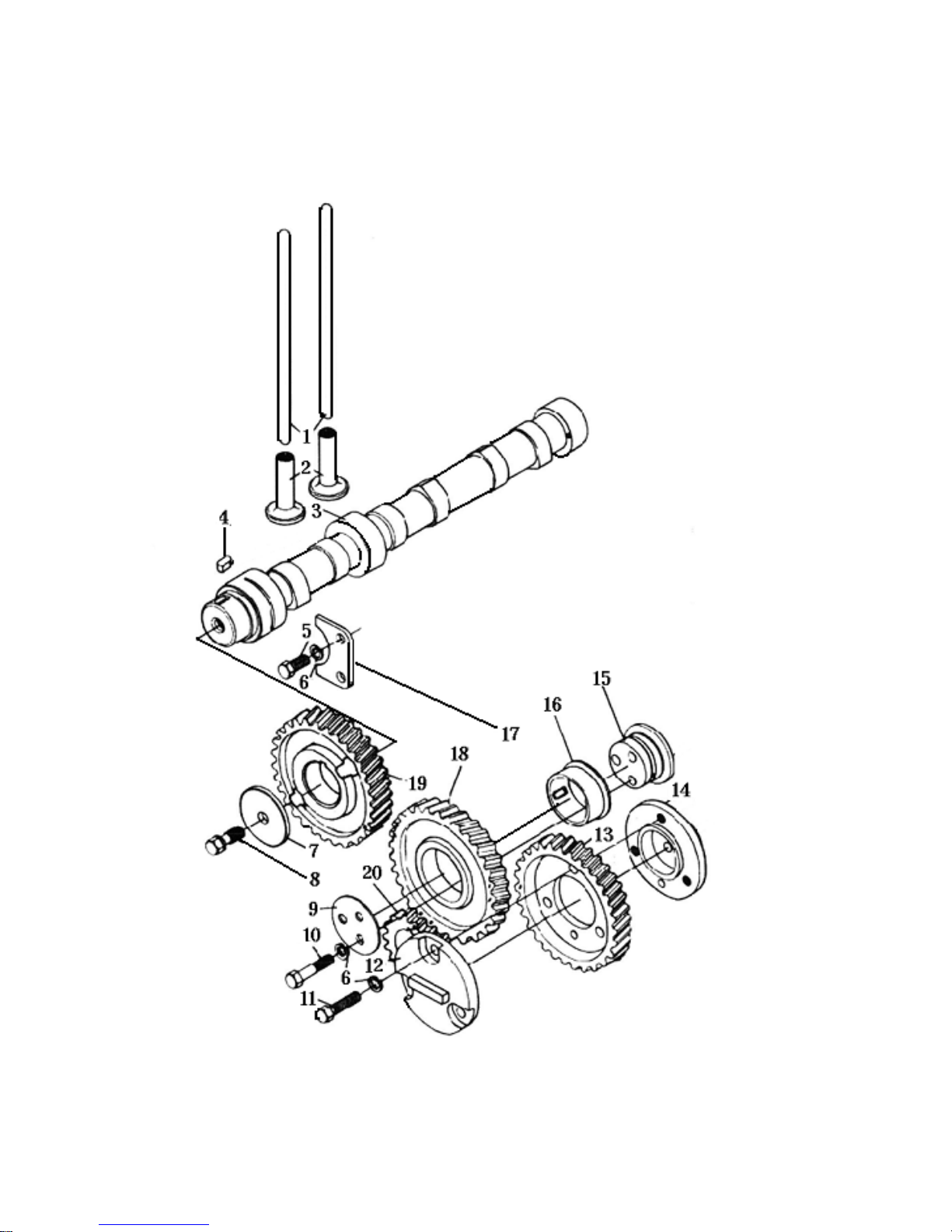
4. CAMSHAFT ASSEMBLY
77
Page 85

4. CAMSHAFT ASSEMBLY
No. Code Name QTY
1
2
3
4
5
6
7
8
9
10
11
12
13
14
TY295.3-3
TY295.3-2
TY395I.3-1EPA
S195-02003
GB5783-86
GB859-87
TY295.3-13
TY295.3-14
TY295.3-9
GB5782-86
GB5783-86
TY2100II.3-10
TY295.3-10
TY295.3-11
Valve push rod
Valve tappet
Camshaft
Flat key
Bolt M8 X 16
Was he r 8
Camshaft gear hold down
Screw
Idle gear hold down
Bolt M8 X 40
Bolt M8 X 25
Drive shield
Fuel injection pump gear
Flange joint of fuel pump
6
6
1
1
2
8
1
3
1
3
3
1
1
1
15
16
17
18
19
20
TY295.3-7
TY295.3-8
TY295.3-5
TY295.3-6
TY295.3-4
Idle gear shaft
Idle gear bush
Thrust piece
Idle gear
Camshaft gear
1
1
1
1
1
1
78
Page 86
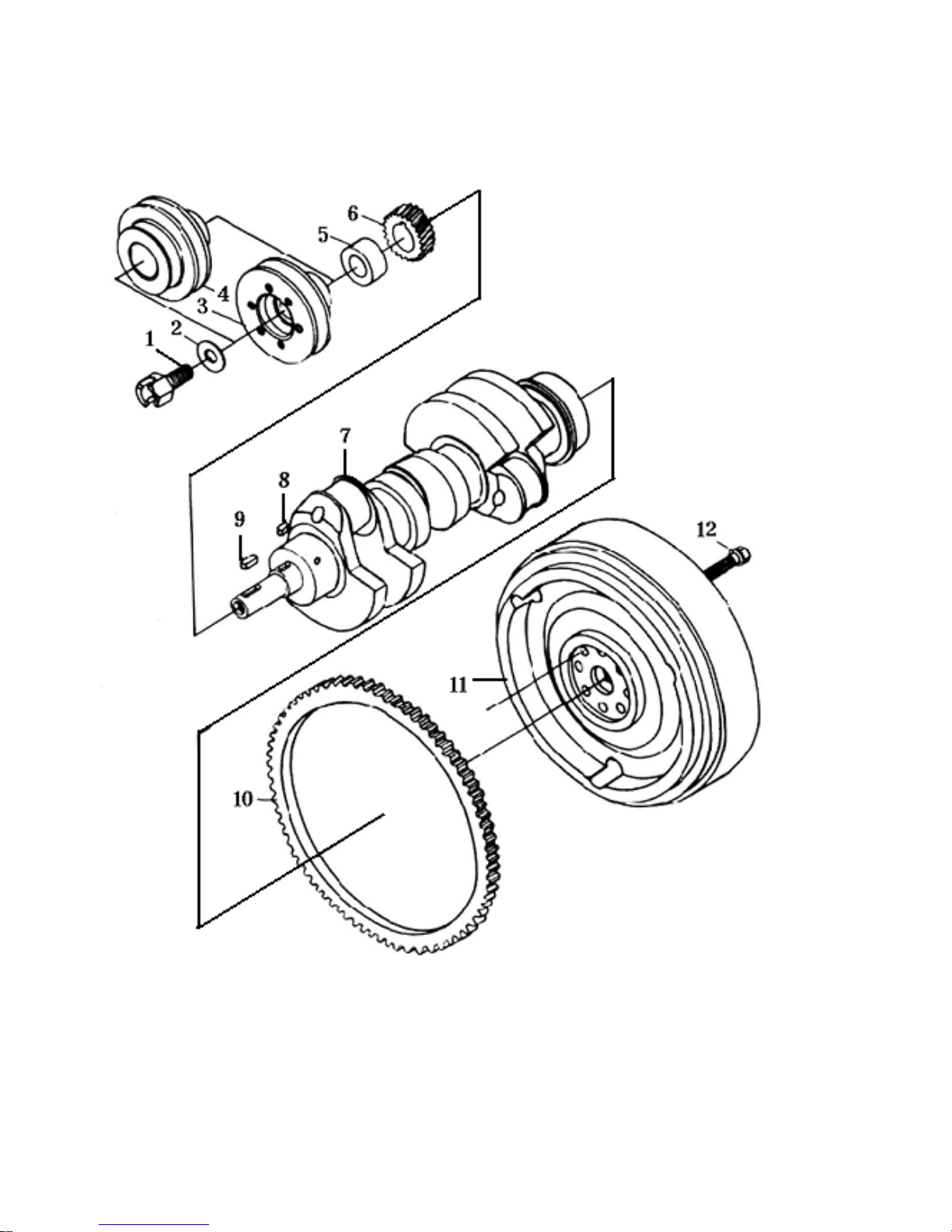
5. CRANKSHAFT-FLYWHEEL ASSEMBLY
79
Page 87

5. CRANKSHAFT-FLYWHEEL ASSEMBLY
No. Code Name QTY
1
2
3
4
5
6
7
8
9
10
11
12
TY295.4.2-7
TY295.4.2-8
TY375I.4.2-9
TY295IT.4.2-9a
TY295.4.2-6
TY295.4.2-5
TY395I.4.2-4
S195-05008
GB1567-79
TY295.4.2-2
TY395I-4.2-1
TY295.4.2-3
Stating claw
Starting claw washer
Belt pulley
Belt pulley
Bush
Crankshaft
Crankshaft
Key
Key A8 X 5 X 28
Flywheel gear ring
Flywheel
Flywheel bolt
1
1
1
1
1
1
1
1
1
1
1
6
80
Page 88
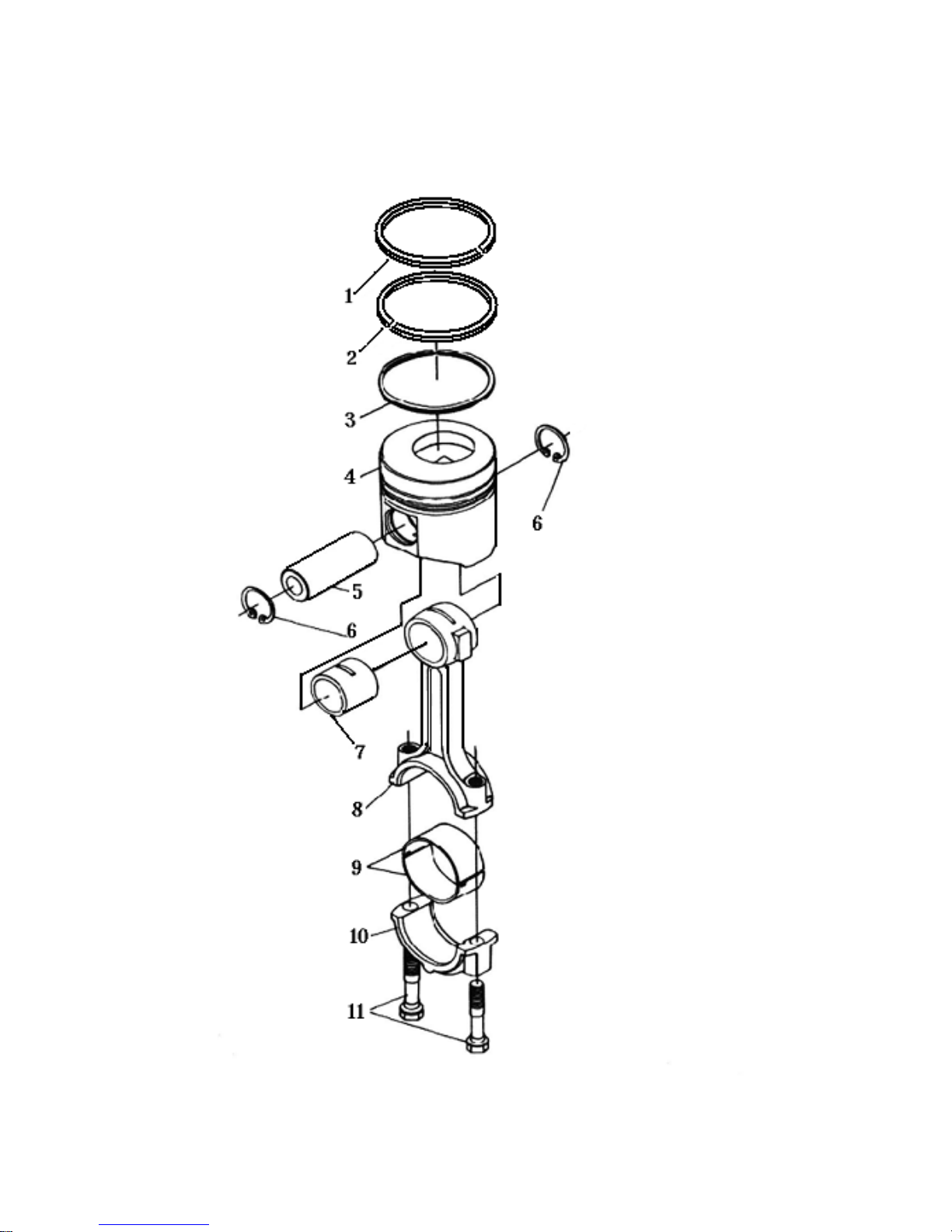
6. PISTON CONNECTING ROD ASSEMBLY
81
Page 89

6. PISTON CONNECTING ROD ASSEMBLY
No. Code Name QTY
1
2
3
4
5
6
7
8
9
10
11
TY395I.4.1-1EPA
TY395I.4.1-1EPA
TY395I.4.1.1EPA
TY395I.4.1-4EPA
TY295.4.1-3
GB893-76
TY395.4.1.2-2
TY295.4.1.2-1
TY295.4.1-6
TY295.4.1.2-3
TY295.4.1.2-4
Compression ring (1)
Compression ring (2)
Oil scraper ring
Piston
Piston pin
Circlip 37
Connecting small rod bushing
Connecting rod assembly
Connecting rod bearing shell
Connecting rod cap
Connecting rod bolt
3
3
3
3
3
6
3
3
3
3
6
82
Page 90
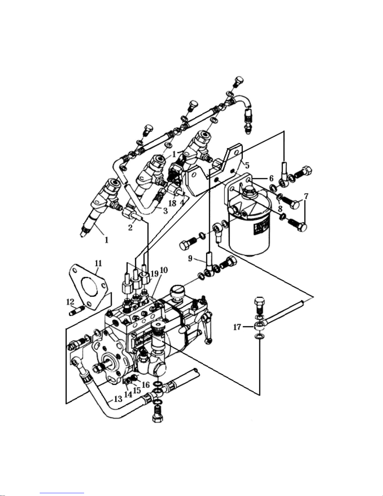
7. FUEL SYSTEM ASSEMBLY
83
Page 91

7. FUEL SYSTEM ASSEMBLY
No. Code Name QTY
1
2
3
4
5
6
7
8
9
10
11
12
13
14
PF68S19
TY395.15.1
TY395.15.7
TY395I.10-3NB
C0708A
GB5782-86
GB859-87
TY395.15.6
TY395.2-7
GB899-88
TY395.14.4
GB848-87
Injection assy
High pressure pipe , cylinder I
Injector fuel return pipe
Heat plug
Cleaner clamp
Fuel filter assy
Bolt M10 X 25
Was he r 1 0
Fuel injection pump
Fuel injection pump gasket
Stud Bolt AM8 X 25
Fuel pipe assy between fuel-tank
transfer-pump and injection-pump
Was he r 8
3
1
1
1
1
1
1
1
1
1
1
3
1
3
3
15
16
17
18
19
20
21
22
23
GB859-87
GB6170-86
TY395.15.5
TY395.15.3
TY395.15.4
TY395I.15.1-1EPA
TY395I.15.6-3EPA
TY395I.15.6-5EPA
TY395I.15.6-6EPA
Was he r 8
Nut M8
Oil return line assembly
High pressure pipe ,cylinder II
High pressure pipe ,cylinder II
150
320
180
84
3
1
1
1
3
2
1
1
Page 92
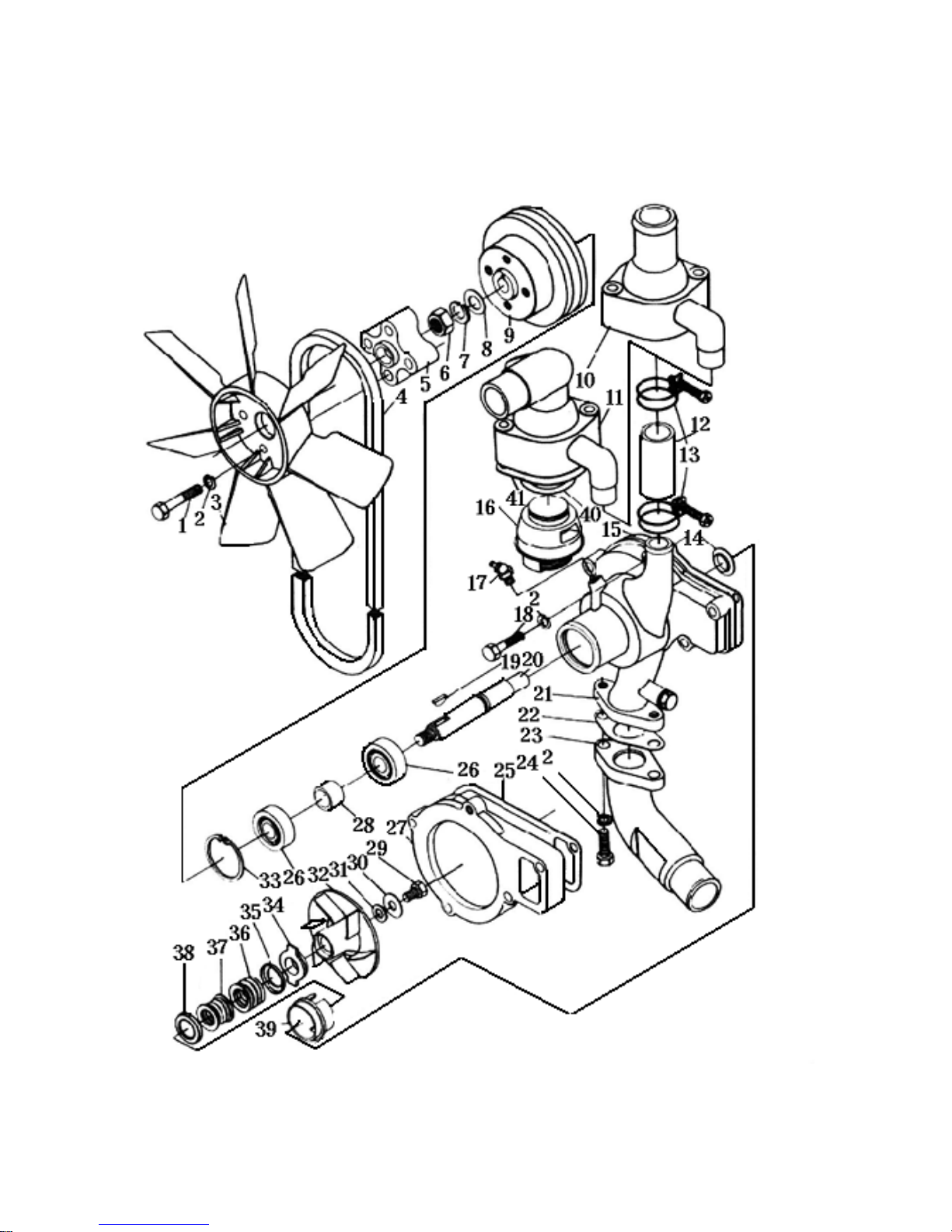
8. COOLING SYSTEM
85
Page 93

8. COOLING SYSTEM
No. Code Name QTY
1
2
3
4
5
6
7
8
9
10
11
12
13
14
GB5782-86
GB859-87
TY395I.12-15
HG4-401-74
TY395I.12-18
GB6173-86
GB859-87
GB9731-85
TY295.12-5
TY295.13-1
TY295IT.13-1
TY295.13-7
TY295.13.3
295-14006
Bolt M8 X 45
Flat Washer 8
Radiator Fan
Fan Belt 13 X 8 X 1000
Radiator Fan
Nut M12
Spring Washer 12
Flat Washer 12
Pulley
Temperature Regulator Upper cap
Temperature Regulator Upper cap
Small water tube
Hoop assembly Φ33
Water thrower
4
7
1
1
1
1
1
1
1
1
1
1
2
1
15
16
17
18
19
20
21
22
23
24
25
26
27
28
TY295.12-13
TY295I.13.5
GB1152-76
GB5782-86
GB1099-79
TY295.12-4
TY295.12-1
TY295.12-7
TY295.13-4
GB5783-86
TY295.12-14
GB278-76
TY295.12-21
TY295.12-12
Water pump washer
Temperature Regulator Assembly
Oil cup
Bolt M8 X 35
Key 5 X 16
Water pump shaft
Water pump assembly
Water pump tube gasket
Lower water tube
Bolt M 8 X 14
Water pump seat washer
Rolling bearing 60203
Water pump seat
Bearing sleeve
1
1
1
1
1
1
1
1
1
2
1
2
1
1
86
Page 94

8. COOLING SYSTEM
No. Code Name QTY
29
30
31
32
33
34
35
36
37
38
39
40
41
GB5783-86
295-14005
GB97.1-85
TY295.12-3
GB893.1-86
295-14100b
TY295.12-9
TY295.12-8
TY295.12-7
TY295.12-9
295-14100a
TY295.13-3
TY295.13-2
Bolt M8 X 14
Locking ring
Was he r 8
Water pump wheel
Circlip 40
Water seal assembly II
Water seal spring seat
Water seal spring
Rubber, water seal
Water seal spring seat
Water seal assembly I
Temperature regulator gasket
Temperature regulator over cap gasket
1
1
1
1
1
1
2
1
1
2
1
1
1
87
Page 95
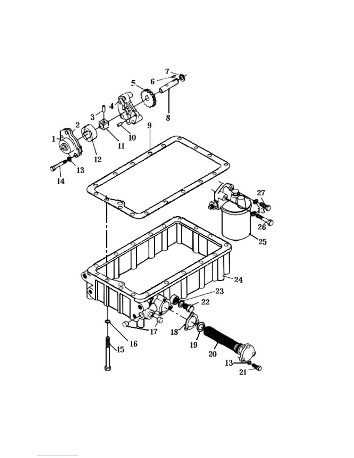
9. LUBRICATION SYSTEM ASSY
88
Page 96

9. LUBRICATION SYSTEM ASSY
No. Code Name QTY
1
2
3
4
5
6
7
8
9
10
11
12
13
14
TY395.5-1
TY395.5-5
TY395.5.1-3
TY395.5-4
TY395.5-3
GB1098-79
GB894.1-86
TY395.5.1-2
TY395.7-2
GB119-86
TY395.5.1-1
TY395.5-2
GB859-87
GB70-85
Upper oil pump body
Upper oil pump body gasket
Pin
Lower oil pump body
Oil pump gear
Key 4 C 65 C 16
Check ring 14
Oil pump shaft
Oil sump gasket
Pin A 5 X 14
Inner rotor
Outer rotor
Was he r 8
Screw M8 X 55
1
1
1
1
1
1
1
1
1
2
1
1
8
3
15
16
17
18
19
20
21
22
23
24
25
26
27
GB5782-86
GB59-87
TY295I.7-7
TY295.7.1-2
TY295I.7.1-3
TY395.7.1.1
GB5782-86
TY295I.7-2
TY295I.7-3
TY395.7-1
J0810A
GB5782-86
GB5783-86
Bolt M10 X 65
Was he r 1 0
Stopper
Oil sucking and straining gasket
Sealing ring
Oil Sucking and Straining Element
Bolt M8 X 22
Oil drain plug
Oil drain plug washer
Oil sump
Oil filter
Bolt M8 X 50
Bolt M8 X 25
18
18
2
1
1
1
3
1
1
1
1
1
1
89
Page 97
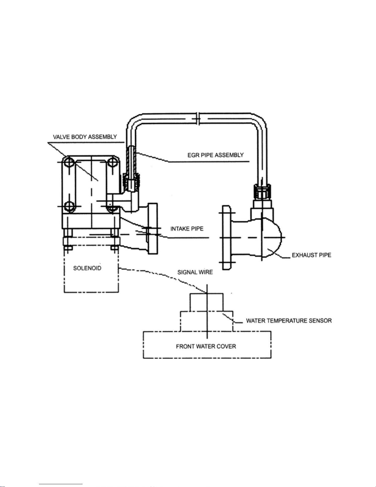
90
Page 98
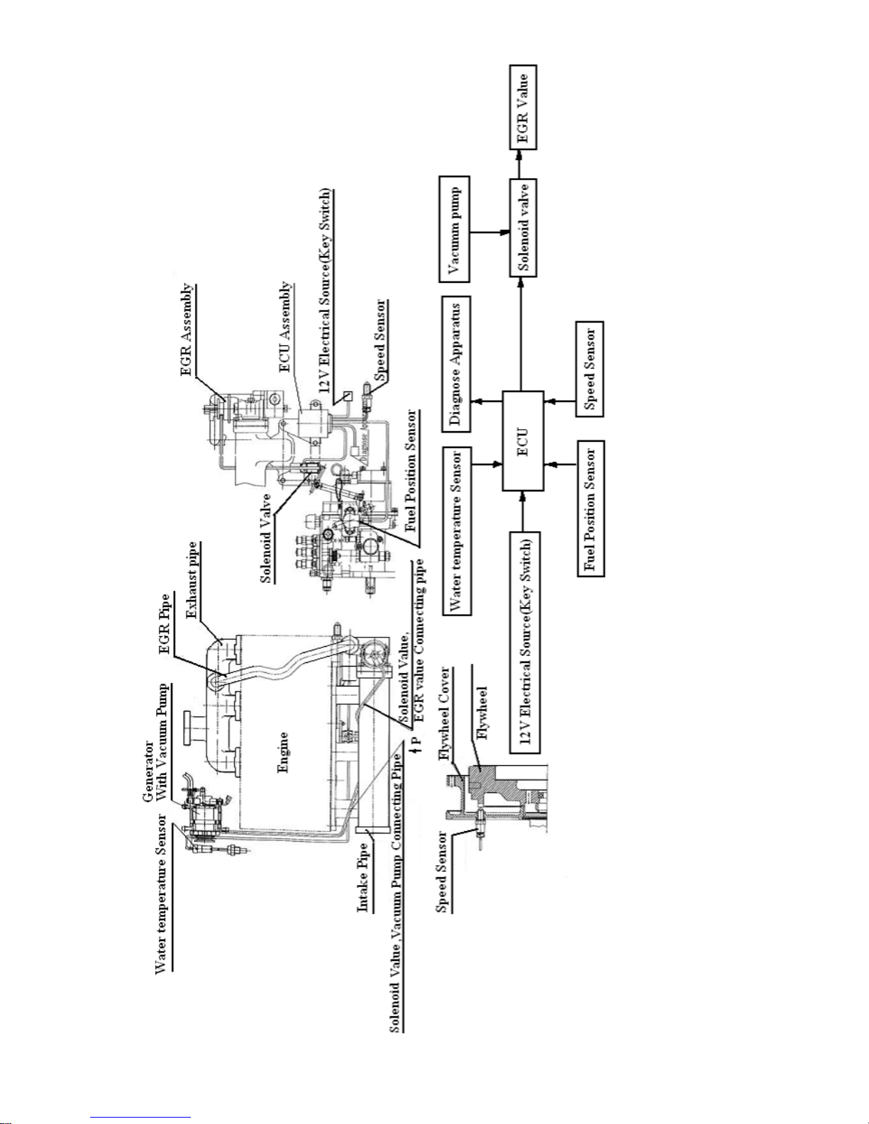
Electric EGR Illustration Diagram
91
Page 99
Appendix I Spare Parts Supplied with the engine
No. Name Quantity
1 Cylinder head gasket 1
2 Valve collect 2
3 Outer valve spring 2
4 Inner valve spring 2
5 Intake valve 2
6 Exhaust valve 2
7 Piston ring 2 set
8 Exhaust pipe packing 2
9 Fuel filter cartridge 1
10 Lube-oil filter cartridge 1
11 Front crankshaft oil seal 1
12 Rear crankshaft oil seal 1
13 Cylinder head cover packing 1
14 Lube – oil filter packing 1
15 Main bearing 1set
16 Connecting rod bearing 1set
Appendix II Tools Supplied with the Engine
No. Name Quantity
1 Valve remover 1
2 Filler gauge (0.35, 0.45) 1set
92
Page 100

ET 350 ECONO 4WD TRACTOR
Chassis
PARTS CATALOGUE
93
 Loading...