

Page 1

RM-iC Series
Quick Start
Installation Guide
Version E0
Part Number UM-068
April 2006
PRODUCT
OVERVIEW
Specifications
The RM-iC series readers provide an enclosed RM-4 board and attached iCLASS read
head, available in the following styles:
RM1-iC - enclosed RM-4 and attached iCLASS read head
RM2-iC - enclosed RM-4 with keypad and attached iCLASS read head
RM2L-iC - enclosed RM-4 with keypad, LCD display, and attached iCLASS read
head.
The RM-iC Quick Start Installation Guide provides a synopsis of installation and
connection information for RM-iC series readers. Refer to the Readers, Inputs, and
Outputs (RIO) Guide for in-depth technical and installation information.
The following specifications apply to all RM-iC series readers:
Power: 12VDC, 300 mA
Cable: Belden 9841
Cable distance from iSTAR or apC: 4,000 ft.
Temperature
Indoor: 32° F to 120° F (0° C to 49° C)
Outdoor: -31° F to 151 ° F (-35 ° C to 66° C)
Qualified on 26-bit, 35-bit, 37-bit, and 32-bit MIFARE serial number formats.
NOTE
Standards
UL has only evaluated the 26-bit HID card format for this unit.
RM-iC series readers are Underwriters Laboratories Inc. (UL), Listed to Standard UL
294, Access Control System Units, Fifth Edition. RM-iC series readers must be wired in
accordance with the National Electrical Code (ANSI/NFPA 70), local codes, and the
authorities having jurisdiction.
1
Page 2
Installation
INSTALLATION
Installing the Mount
Plate
Installing an RM-iC series reader involves:
1. Installing the mount plate
2. Wiring the components
3. Connecting and grounding the cable shields on the reader bus
4. Setting the RM-4 (reader) address
5. Installing the ARM-1 relay board (optional)
6. Installing the heater kit. (optional)
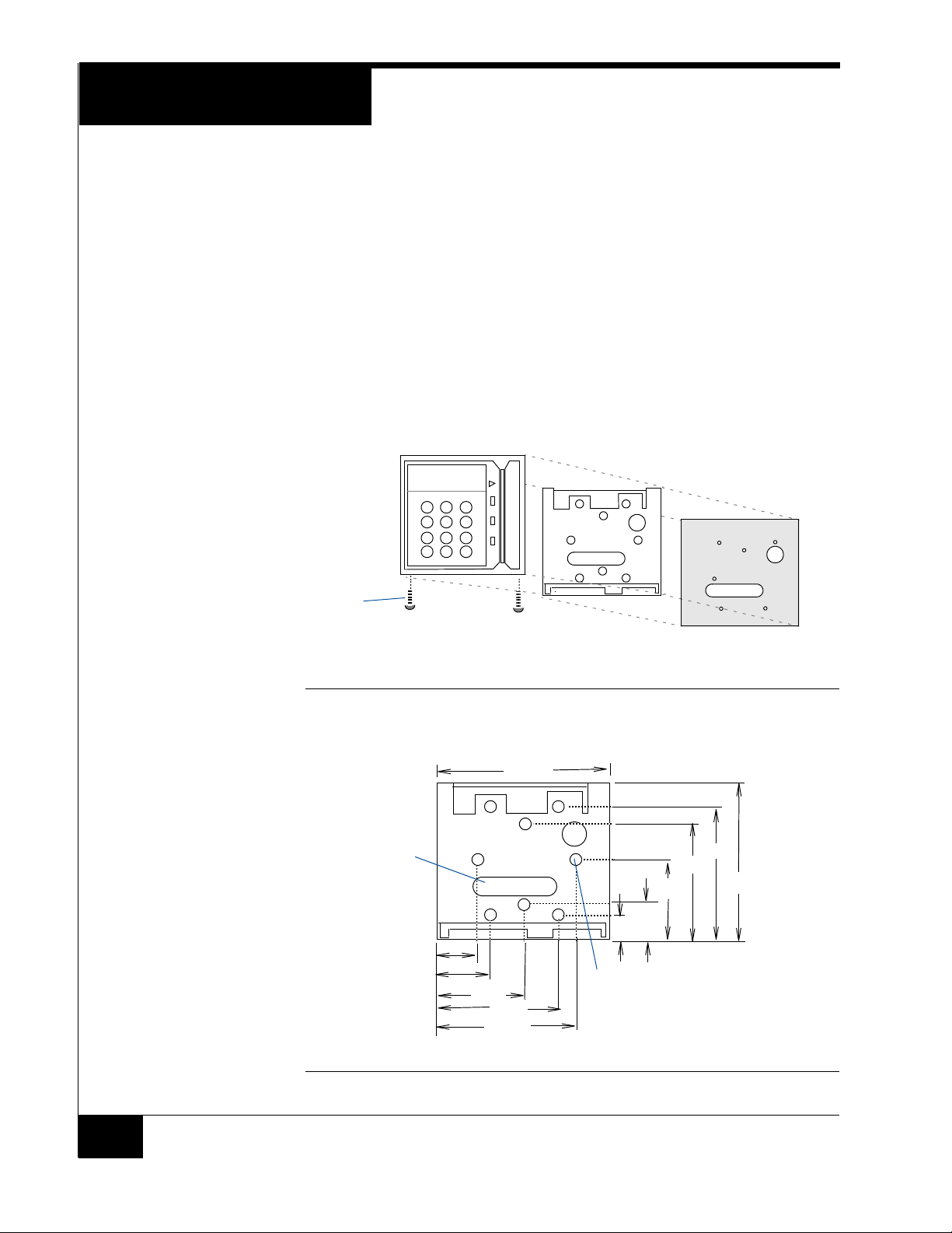
Figure 1 shows RM-iC standard housing, mount plate, and gasket. All RM-iC series
readers conform to the same housing, mount plate, and gasket dimensions.
Housing
screws
Requires a security screwdriver
Standard Housing
Standard mount plate
Gasket
FIGURE 1. Standard Housing and Mount Plate
Figure 2 shows mount plate dimensions.
5.45"
Wiring
access
1.54"
1.82"
2.73"
3.64"
3.92"
FIGURE 2. Mount Plate Dimensions
4.11"
3.66"
2.47"
1.29"
.83"
8x
Mounting hole
0.156" Thru, 0.280” Countersink
4.94"
2
Page 3
Installation
This device has been approved for outdoor use when properly installed with RM
Heater Kit Installation (P.N. 130-915) and the supplied gasket material. Position
the gasket with the RM plate so that the mounting holes are properly aligned.
Ensure that the gasket is placed between the mounting surface and mating
surface of the RM plate. Fasten the RM plate to the mounting surface with the
gasket material in between. Install the gasket so that no gaps or wrinkles are
present.
Wiring the Inputs,
Outputs, Reader Bus
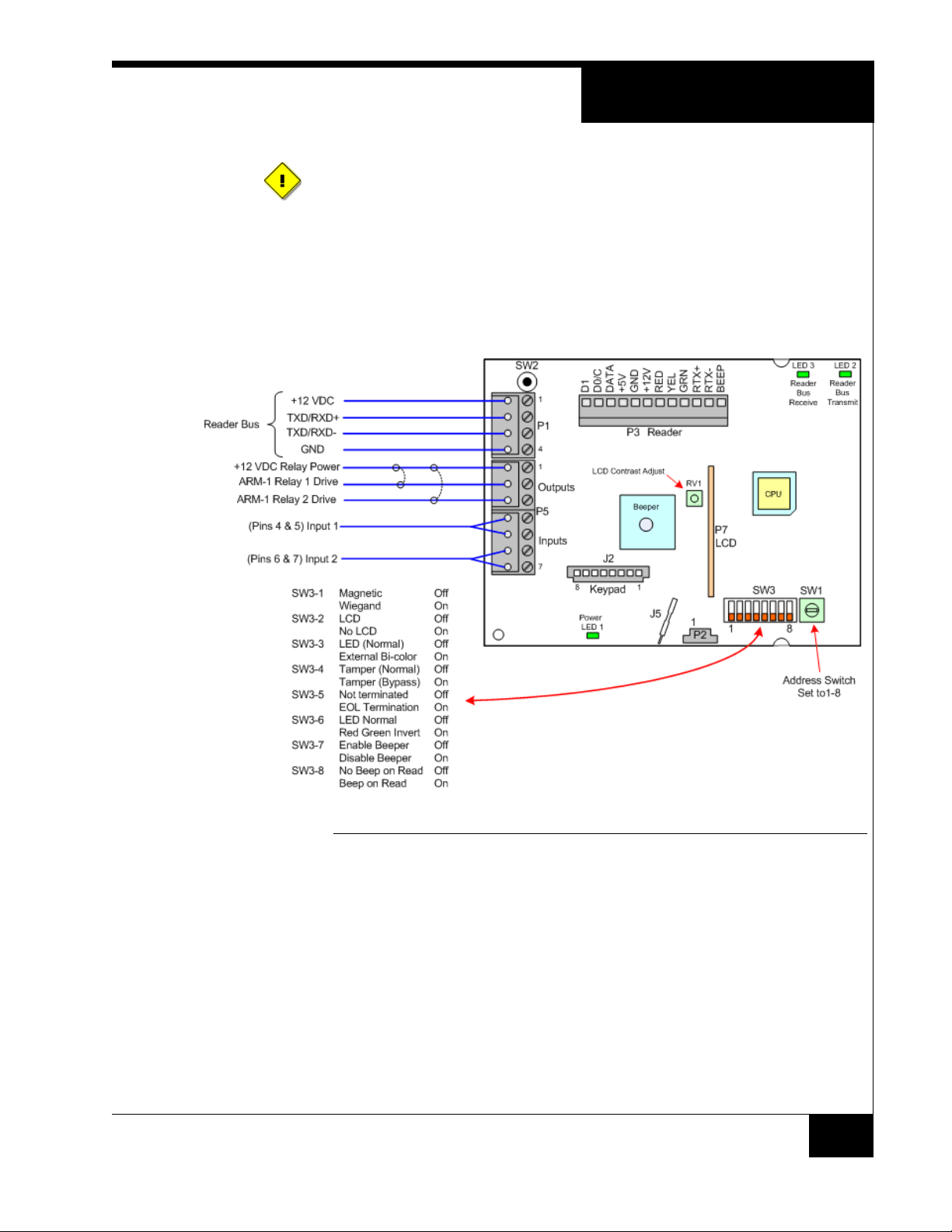
Figure 3 shows RM-4 P1 and P5 wiring.
FIGURE 3. RM-4 Wiring Requirements
3
Page 4
Installation
Wiring the Reader
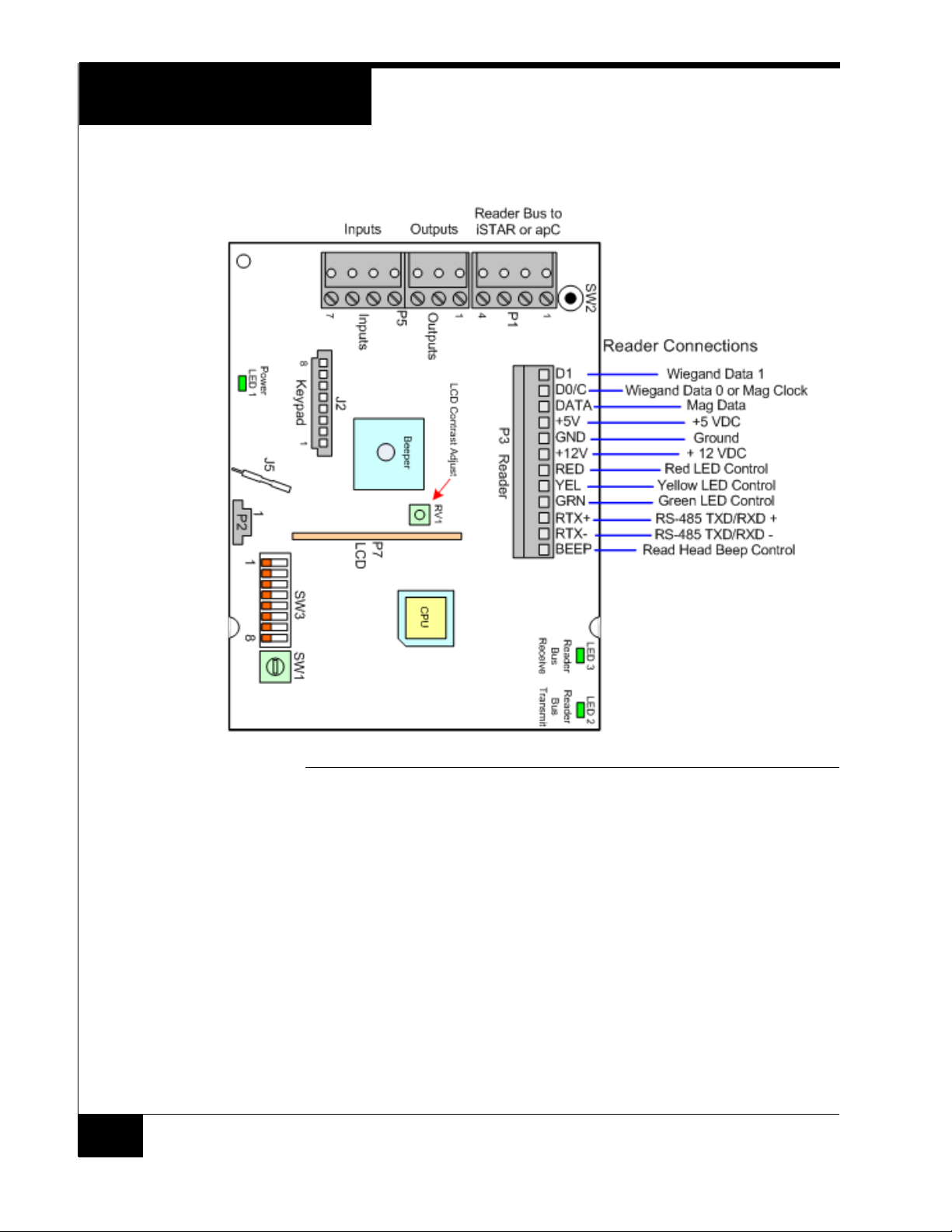
Figure 4 shows RM-4 P1 and P5 wiring.
FIGURE 4. RM-4 Reader Wiring
4
Page 5
Installation
Grounding and
Shielding
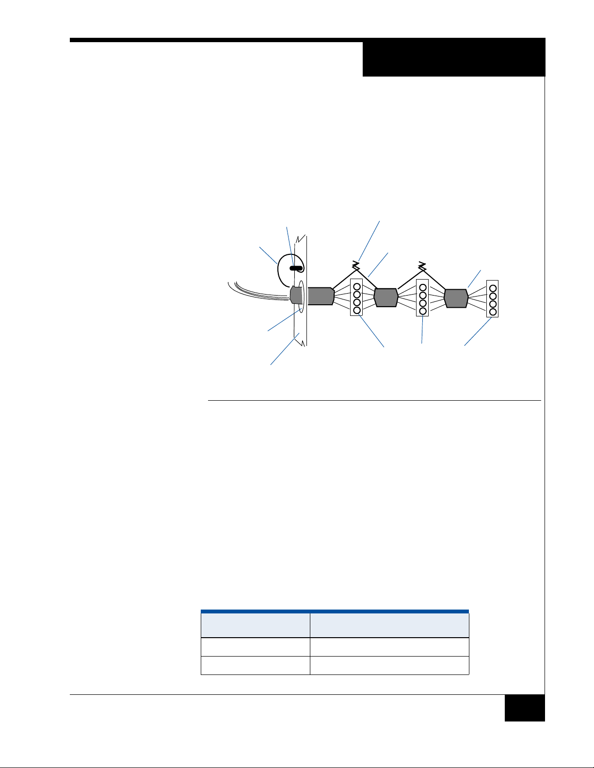
When bus wiring more than one RM-iC reader (Figure 5 ):
1. Attach the shields along the bus together (insulate each connection). Snip off the
shield wire at the end of the bus.
2. Attach the shield to the ground at only one point, the ground stud inside the cabinet
adjacent to the knockout.
3. Attach a local earth ground (18 or 22 gauge) wire to the J5 component.
Twist shield wires together and insulate
Ground stud
Shield wire
ACM module
Knockout
Enclosure/cabinet
(do not ground)
RS-485 connector on a reader
Shield wire
(bus configuration)
Snip off shield
wire at end of
bus
Setting Module
Address and
EOL Termination
Installing the ARM-1
Relay
FIGURE 5. Reader Shield Wiring
To set the module address, set SW1 (16 position rotary switch) to a number from one to
eight. Every RM-iC series reader on a bus must have a unique address.
To set RS-485 EOL termination, set SW3-5 to the On (closed) position if the module is
the last unit in the bus. If the module is not last, SW3-5 should be Off (open).
Two ARM-1 relay components can be connected to the RM-iC series reader through the
P5 connector (Table 1 ).
P5-1 is the common (+12 VDC) pin for either ARM-1.
P5-2 is the output drive (GND) for the first relay.
P5-3 is the output drive (GND) for the second relay.
TABLE 1. ARM-1 Wiring
Module Wiring
ARM-1 Relay P2-1 to RM P5-1, P2-2 to RM P5-2
ARM-2 Relay P2-1 to RM P5-1, P2-2 to RM P5-3
5
Page 6
Installation
NOTE
Installing the Heater
The ARM-1 has not been evaluated by UL.
RM-iC readers require a heater kit (Model 130-915) when installed outdoors in an
environment and where temperatures may drop below 40° F (5° C).
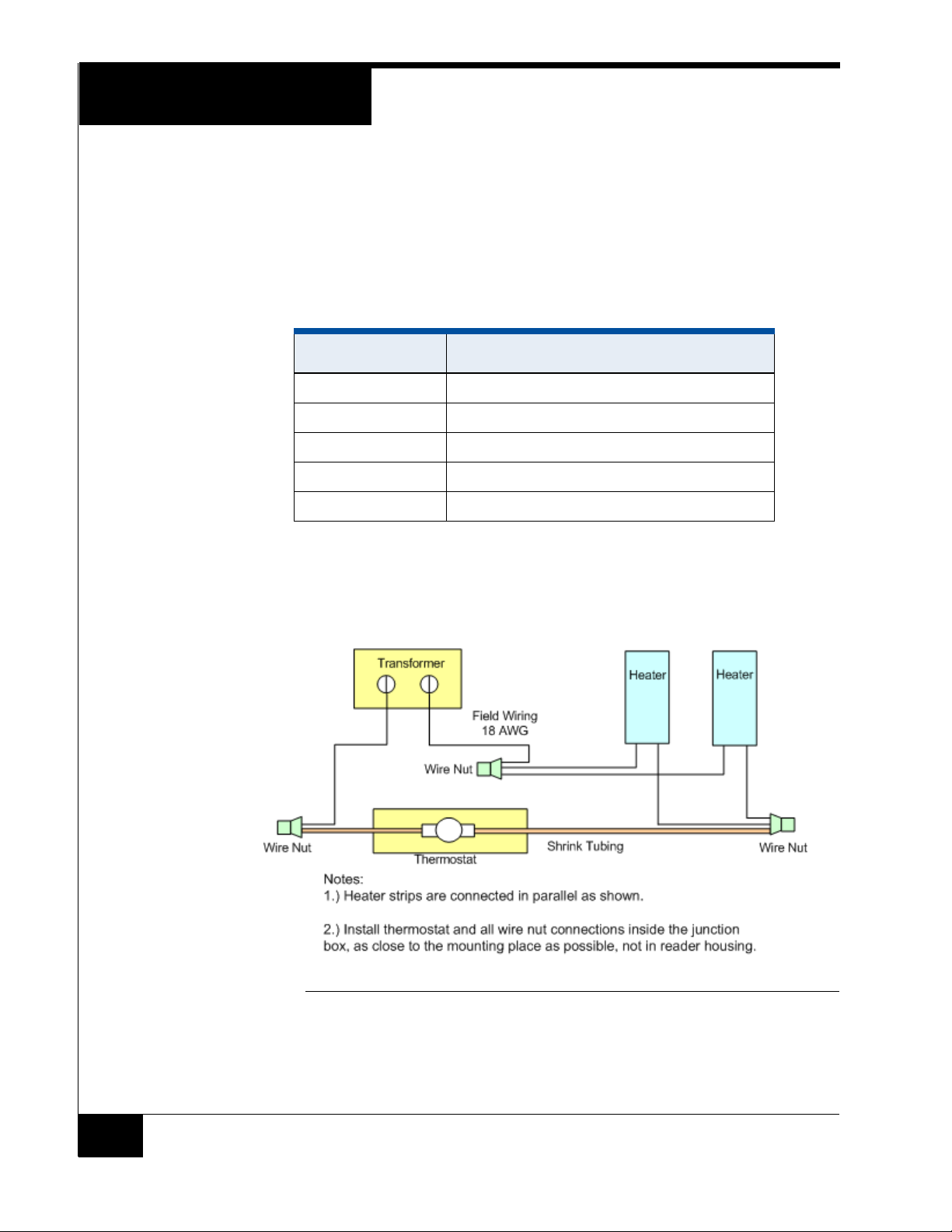
The Model 130-915 heater kit contains the following parts:
TABLE 2. Heater Parts
Quantity Description
1 Transformer 12 VAC 40VA
2 Heater Strips
1 Thermostat (turns on at 40 ° F)
3 Wire nuts
2 6-32 x 1/4” screws to mount thermostat to RM plate.
Part # 130-915A is supplied without a transformer. A UL Listed Class 2 transformer
rated output 12 VAC, 40 VA is required for proper installation.
Figure 6 shows RM/heater wiring.
FIGURE 6. RM/Heater Wiring
6
Page 7
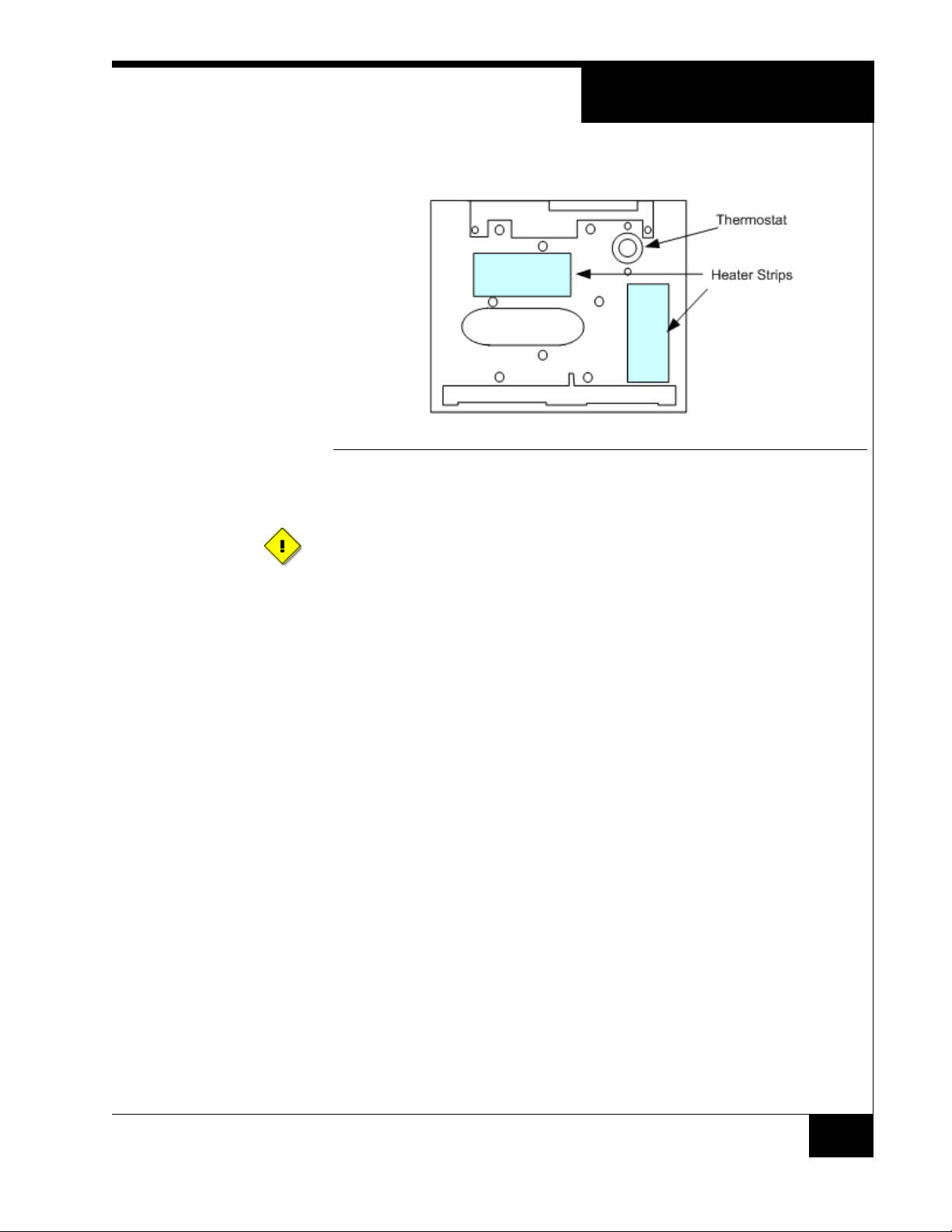
Figure 7 shows RM installation
.
FIGURE 7. RM Installation
Heater Strip Application
To avoid problems such as placing the strips too far away from the thermostat, not
allowing the thermostat to shut off, or locating the strips too close to the PCB and
causing component over-temperature concerns, follow mounting diagram and
heater strip application instructions.
Installation
To apply the heater strip:
1. Clean the attachment surface of the back plate with a solvent such as alcohol (use all
required precautions when handling solvents).
2. Carefully remove the release film from the adhesive.
3. Locate the heater on the clean surface of the back plate exactly as shown in Figure 6.
4. Gently roll in place to remove air bubbles.
5. Allow to remain for 72 hours before use, for maximum adhesion.
Air gaps or bubbles under the heater cause localized overheating and possible heater
burnout. Also, application of adhesives at temperatures below 50° F is not
recommended.
Installing the Thermostat
To install the thermostat:
1. Fasten the thermostat to the RM plate with the body of the device facing the junction
box and the face sitting flat against the RM plate surface.
2. With the back (or outside) surface facing up, align the thermostat such that the screw
holes of the thermostat allow for the 6-32 x 1/4" screws to secure the device to the
RM plate.
7
Page 8

Testing with apC or iSTAR hardware
3. Use two (Quantity 2) 6-32 x 1/4" screws to mount the thermostat to the RM Plate.
Tighten the screws allowing the thermostat to be sufficiently secured to the plate. Do
not over tighten the screws.
TESTING WITH APC
OR ISTAR
HARDWARE
To test an RM-iC series reader with an apC or iSTAR:
1. Measure the supply voltage to the RM-4.
The voltage can be measured between pin 1 (+12 VDC supply) and pin 4 (ground)
on the P4 connector. The voltage must be +12 VDC (+/-5%).
2. Check the RM-iC reader address setting.
The RM-iC must be set to an unused address, between 1 and 8, when connected to
the apC or iSTAR. Use rotary switch SW1 to set the reader address.
3. Check the RM-4 for communications to the apC or iSTAR. Observe LED2 and
LED3.
4. Check the supervised inputs. Configure the inputs on the apC or iSTAR.
With no switches or resistors connected to the supervised input 1 and 2 lines, the C•
CURE 800/8000 Monitoring Program should report inputs as “Open Loop”. When
you connect the 1,000-ohm resistor to the input terminals, the C• CURE 800/8000
Monitoring Program should report that the input as “Deactivated”. Supervised
inputs #1 is found at pins 4 and 5 of P5. Supervised input #2 is found at pins 6 and 7
of P5.
5. Check the outputs.
The outputs can be functionally tested by using the “momentary activate” feature in
the C• CURE 800/8000 Monitoring Program. When the outputs are momentarily
activated, the signal will change state for a few seconds. A 1,000 ohm resistor and an
LED can be connected to the output to obverse the functionality. Connect the
resistor to pin 1 of P5 (+12VDC). Connect the anode of the LED to the resistor and
connect the cathode to pin 2 of P5 for output #1 and to pin 3 of P5 for output #2.
6. Check the reader interface.
The reader interface can only be tested with the reader chosen for the installation.
Reading a card will cause the display to show “Access Granted” or “Access
Denied”, depending upon the clearance of the card.
8
Page 9
Testing Readers with iSTAR PRO Hardware
TESTING READERS
WITH
ISTAR PRO
HARDWARE
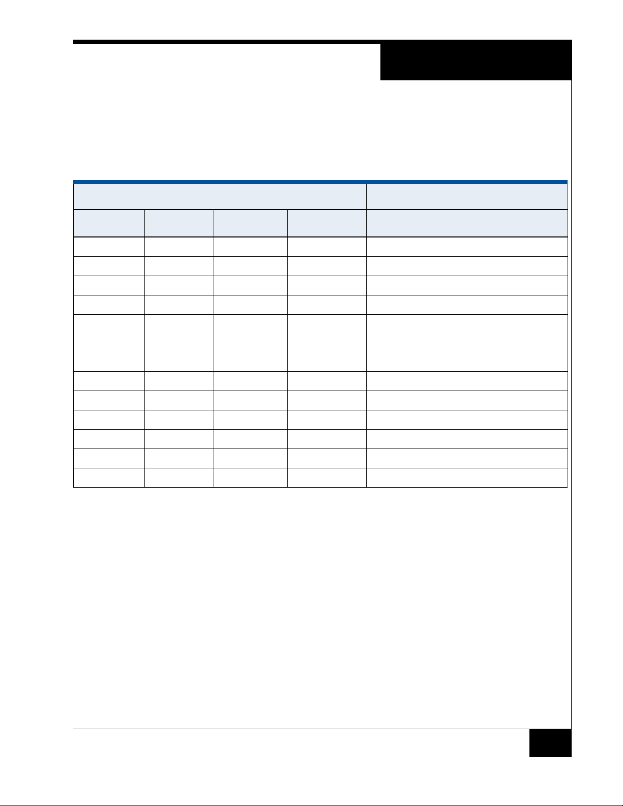
To test an RM-iC series reader with iSTAR Pro, use the iSTAR Pro S4 switch, positions
5 through 8.
Table 3 shows S4 settings for Positions 5 through 8.
TABLE 3. S4 Diagnostic Settings
Switch Setting Description
Position 5 Position 6 Position 7 Position 8
Off Off Off Off Display status messages (ICU Block Off)
On On On On Display status messages (ICU Block On)
Off Off Off On Display card data
Off On Off On Display card data in fast mode
Off Off (2 second
LCD display)
On (1 second
LCD display)
Off Off On On Manual output test (RMs and R/8s)
Off On Off Off Automatic ACM output test
On Off Test inputs
Off On On On Automatic output test (including RMs and R/8s)
On Off Off Off Ethernet/PCMCIA port and device test
On On Off Off DIMM memory test
On Off Off On Battery charger test
9
Page 10
Canadian Radio Emissions Requirements
CANADIAN RADIO
EMISSIONS
REQUIREMENTS
FCC DIGITAL
DEVICE
LIMITATIONS
This digital apparatus does not exceed the Class A limits for radio noise emissions from
digital apparatus set out in the Radio Interference Regulations of the Canadian
Department of Communications.
Le present appareil numerique n’emet pas de bruits radioelectriques depassant les
limites applicables aux appareils numeriques de la class A prescrites dans le Reglement
sur le brouillage radiolelectrique edicte par le ministere des Communications du
Canada.
Radio and Television Interference
This equipment has been tested and found to comply with the limits for a digital
device, pursuant to Part 15 of the FCC rules. These limits are designed to provide
reasonable protection against harmful interference when the equipment is
operated in a commercial environment. This equipment generates, uses, and can
radiate radio frequency energy and, if not installed and used in accordance with
the instruction manual, may cause harmful interference to radio communications.
Operation of this equipment in a residential area is likely to cause harmful
interference, in which case the user will be required to correct the interference at
his own expense.
Operation is subject to the following two conditions: (1) This device may not cause
harmful interference, and (2) this device must accept any interference received,
including interference that may cause undesired operation.
In order to maintain compliance with FCC regulations, shielded cables must be
used with this equipment. Operation with non-approved equipment or unshielded
cables is likely to result in interference to radio and television reception.
Caution: Changes or modifications not expressly approved by the manufacturer
could void the user’s authority to operate this equipment.
10
 Loading...