

Page 1
Model RC-1 Retard Chamber
For Variable Pressure Wet Pipe Sprinkler Systems
300 psi (20,7 bar)
Tech ni cal Service s: Tel: (800) 381-9312 / Fax: (800) 791-5500
Page 1 of 4 JULY 2009 TFP920
General
Description
The Tyco® Model RC-1 Retard
Chamber is required in installations
that will be subject to pressure variations, as are generally associated with
public water supplies, in order to help
prevent false alarms. The RC-1 is specifically intended for use as a separately ordered item for the Model AV-1-300
Alarm Check Valve ( TFP910). It can,
however, also be used as a separately
ordered item for changing out older
style Retard Chambers used with the
Central Model F/G, Gem Model A, or
Star Model E/F Alarm Check Valves.
The Model RC-1 Retarding Chamber
is a re-designation for the Gem Model
F211 for use with Gem Model F20/
F200/F2001 Alarm Check Valves, as
well as the Star Model S310 for use
with Star Model S30/S300/S3001
Alarm Check Valves.
NOTICE
The Mode l RC-1 Retard Chamber
described herein must be installed
and maintained in compliance with
this document, as well as with the
applicable standards of the National
Fire Protection Association, in addition
to the standards of any other authorities
having jurisdiction. Failure to do so may
impair the integrity of this device.
The owner is responsible for maintaining
their fire protection system and devices
in proper operating condition. The
insta lli ng co ntr actor o r s pri nkl er
manufacturer should be contacted
relative to any questions.
Technical
Data
Approvals
UL and ULC Listed, as well as
FM Approved for use with the Model
AV-1-300 Alarm Check Valves.
UL and ULC Listed, as well as FM,
LPCB, and VdS Approved for use with
the following Alarm Check Valves:
Model AV-1-175
Gem Model F20/F200/F2001
Gem Model A
Star Model S30/S300/S3001
Working Water Pressure
300 psi (20,7 bar)
Construction
The Model RC-1 Retard Chamber
shown in Figure 1 is cast iron, and a
3/4” x 1/2” x 3/4” Tee is provided at
the outlet (top) for connection of a
pressure alarm switch and/or water
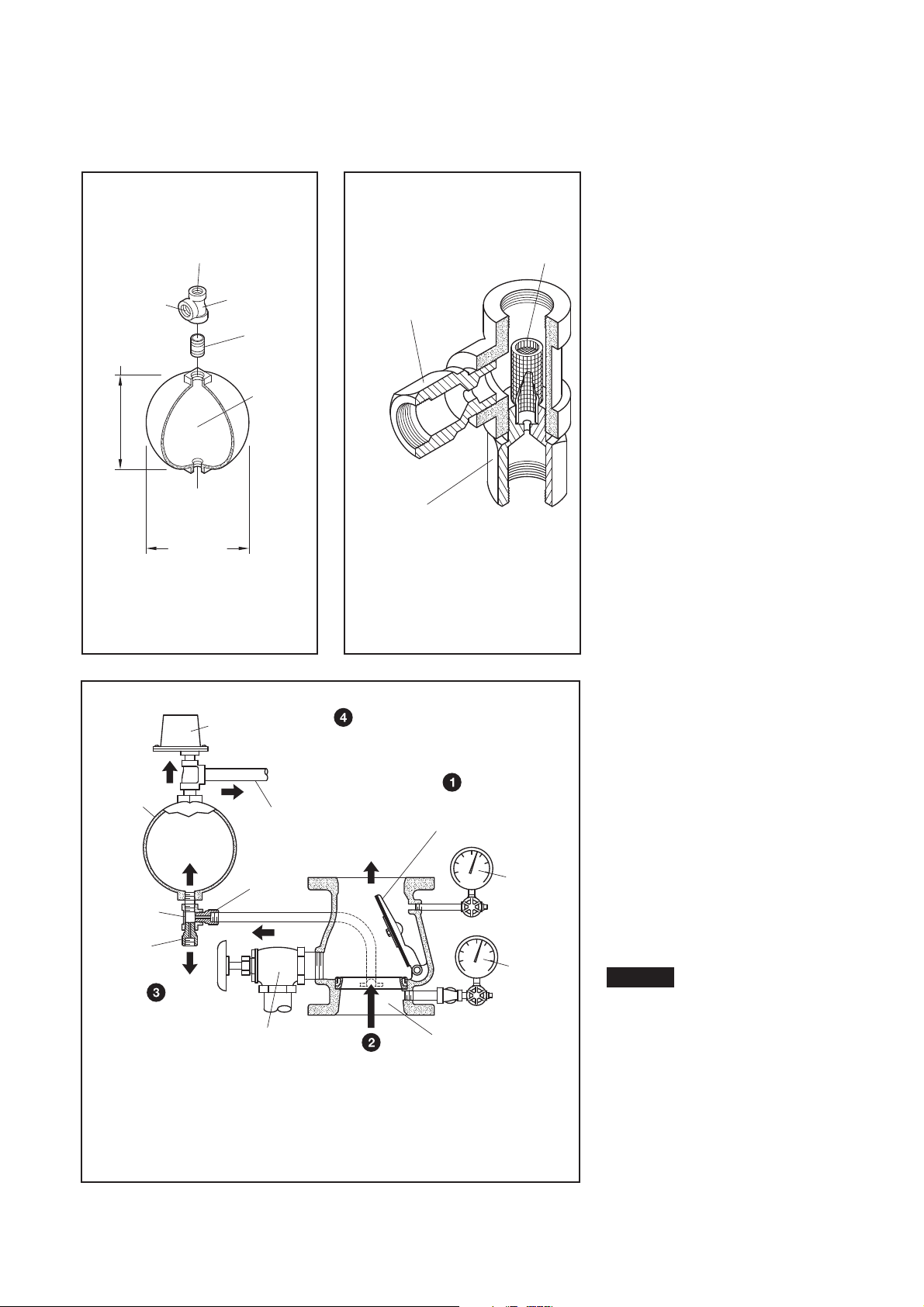
motor alarm. The Restriction Assembly shown in Figure 2 is provided with
the AV-1-300 trim or ordered separately for retrofitting other valves. This
assembly is comprised of brass restrictions assembled to a cast iron or
malleable iron threaded tee fitting. The
screen is stainless steel.
Operation
When water flows steadily into the
sprinkler system due to sprinkler operation, the Waterway Clapper in the
Alarm Check Valve opens as shown
in Figure 3. Water is then permitted to
flow into the centrally located groove
in the Seat Ring and out through the
Alarm Port towards the Restriction Assembly (Figure 2).
When the flow through the Inlet Restriction of the Restriction Assembly
exceeds the flow out through the Outlet Restriction, the Retard Chamber
begins to fill. Subsequently, the Water Motor Alarm and/or the Pressure
Alarm Switch activate. The alarms continue to operate as long as the Waterway Clapper remains open. When the
Clapper closes as a result of discontinued water flow, water in the alarm
lines automatically drains out through
the 1/8 inch (3,2 mm) drain orifice in
the Restriction Assembly ( Figure 2).
In the case of variable pressure systems, a transient surge in supply pressure that is sufficient only to open the
Clapper momentarily will not cause a
false alarm. The volume of the Retard
Chamber is sufficiently large enough
that it will not fill to operate the connected alarm devices. Any water in
the alarm line is then automatically
drained, further reducing the possibility of a false alarm due to a successive
transient surge in supply pressure.
Page 2
3/4" x 1/2" x 3/4"
REDUCING TEE
3/4" x 1-1/2"
END-TO-END
8-1/8"
(206,0 mm)
DIA.
1/2" NPT INLET
CONNECTION
3/4" NPT WATER
CONNECTION
MOTOR ALARM
9-1/8"
(232,0 mm)
WATERFLOW
CONNECTION
PRESSURE
ALARM SWITCH
1/2" NPT
1 GAL.
(3,8 L)
CAPACITY
NOMINAL
NIPPLE
SCREEN
ORIFICE
ORIFICE
WITH 0.125" (3.2 mm)
RESTRICTION FITTING
WITH 0.219" (5.6 mm)
RESTRICTION FITTING
DRAIN
INLET
PRESSURE
WATERFLOW
ALARM SWITCH
MOTOR ALARM
VALVE
RESTRICTION
(3,2 mm)
OUTLET
ORIFICE
RETARD CHAMBER
BEGINS TO FILL
INLET EXCEEDS OUTLET,
RESTRICTION ASSEMBLY
WHEN FLOW THROUGH
ASSEMBLY
1/8"
CHAMBER
RETARD
INLET
ALARM PORT
RING GROOVE AND
THROUGH SEAT
WATERFLOW
MAIN
DRAIN
ALARM ACTUATE
WATERFLOW PRESSURE
CHAMBER OVERFLOWS,
ONCE RETARD
WATER MOTOR
ALARM SWITCH AND
WATERFLOW
TO SYSTEM
WATERFLOW
TO WATER
7/32"
ORIFICE
(5,6 mm)
UPON SPRINKLER
FLOW, WATERWAY
CLAPPER OPENS
GAUGE
GAUGE
SUPPLY
PRESSURE
PRESSURE
SYSTEM
CHECK
VALVE
ALARM
TFP920
Page 2 of 4
Installation
The Tyco® Model RC-1 Retard Chamber must be installed in accordance
with the specific instructions provided
with the Tyco® Model AV-1-300 Alarm
Check Valve (TFP910). The standard
trim for these Alarm Check Valves includes all necessary components including the Restriction Assembly
shown in Figure 2.
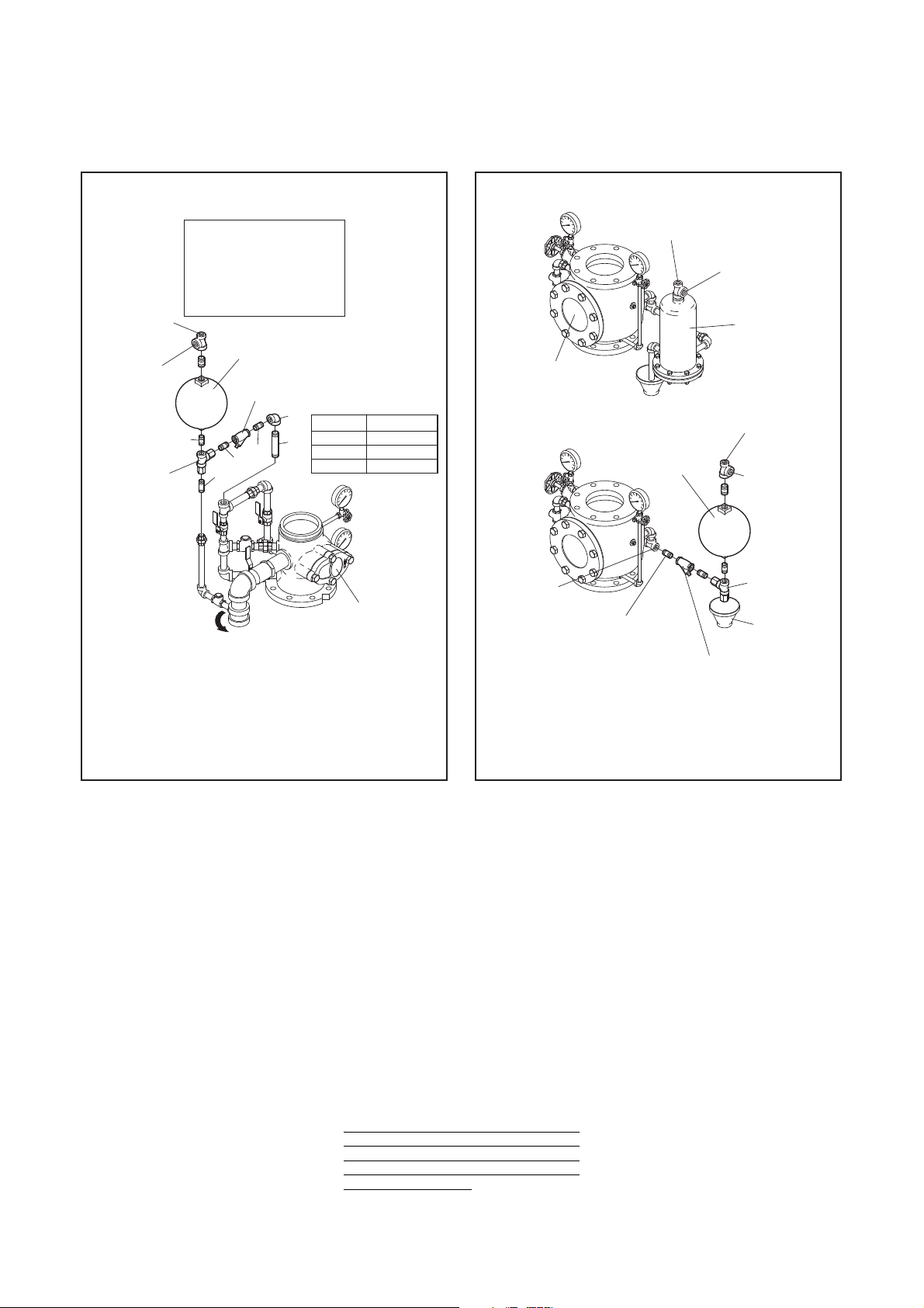
s)NTHECASEOFRETROlTTING#ENTRAL
Model F/G Alarm Check Valves, refer to Figure 4.
s)NTHECASEOFRETROlTTING'EM-OD-
el A Alarm Check Valves, refer to
Figure 5.
s)NTHECASEOFRETROlTTING3TAR-OD-
el E/F Alarm Check Valves, refer to
Figures 6 and 7.
Apply pipe thread sealant sparingly to
male threads only.
Care and
Maintenance
Responsibility lies with the owner for
the inspection, testing, and maintenance of their fire protection system
and devices in compliance with this
document, as well as with the applicable standards of the National Fire
Protection Association (for example,
NFPA 25), in addition to the standards
of any authority having jurisdiction.
Contact the installing contractor or
product manufacturer regarding any
questions.
Automatic sprinkler systems should
be inspected, tested, and maintained
by a qualified Inspection Service in
accordance with local requirements
and/or national codes.
Specific consideration must be given
to cleaning the Screen within the Restriction Assembly, as well as the YStrainer. More frequent cleaning than
that required by NFPA 25 may be necessary as determined after the first inspection and is a function of the water quality with respect to water borne
debris.
NOTICE
Bef ore c los ing a f i re pr ote cti o n
system control valve for inspection
or m aintenanc e wor k o n th e f ire
protection system that it controls, obtain
permission to shut down the affected
fire protection system from the proper
authorities, and notify all personnel who
may be affected by this action.
After placing a fire protection system
in service, notify the proper authorities
an d a dvis e those responsible for
monitoring proprietary and/or central
station alarms.
FIGURE 2
RESTRICTION ASSEMBLY
FIGURE 3
MODEL RC-1 RETARD CHAMBER
OPERATION
FIGURE 1
MODEL RC-1
RETARD CHAMBER
Page 3
1/2" x 2" Nipple
Select per Table
DESCRIPTION
3/4" x 1/2" 90°
Reducing Elbow
NIPPLES & FITTINGS
1/2" x 1-1/2" Nipple
3
4
1
2
NO.
than TFSBP.
Includes nipple and
tee per Figure 1.
Nipples & fittings
from sources other
may be acquired
1. . . . . . . .
. . . . . . .
2
1
1
. . . . . . . .
. . . . .3
1
QTY.
1
P/N 52-353-1-005
1/2" Y-STRAINER
RETARD CHAMBER
P/N 52-211-1-002
RETARD CHAMBER DRAIN TRIM
3
RESTRICTION
ASSEMBLY
P/N 92-210-1-005
TO ACCOMMODATE NEW
RETARD CHAMBER TRIM
(SEE FIGURE 2)
ROTATE EXISTING
WATERFLOW
CONNECTION
PRESSURE
ALARM SWITCH
1/2" NPT
3/4" NPT WATER
CONNECTION
MOTOR ALARM
2
2
WITH ALARM TRIM
REFER TO DATA
SHEET 7-3.0
(6"/DN150 SHOWN)
ALARM CHECK VALVE
CENTRAL MODEL F/G
2
4
1
MODEL RC-1
2
8" (DN200) 3/4" x 1-1/2"
3/4" x 4-1/2"
Nipple 4 SizeValve
4" (DN100)
6" (DN150)
3/4" x 6"
ALARM SWITCH
PRESSURE
CONNECTION
WATERFLOW
1/2" Y-STRAINER
P/N 52-353-1-005
VALVE SIZE & TRIM
LENGTHS TO SUIT
ARRANGEMENT
NIPPLE
WITH BASIC TRIM
ALARM CHECK VALVE
(6"/DN150 SHOWN)
REFER TO DATA
GEM MODEL A
SHEET TD1
MOTOR ALARM
POINT
CONNECTION
DRIP FUNNEL
(IF REQUIRED)
P/N 92-210-1-005
ASSEMBLY
(SEE FIGURE 2)
RESTRICTION
1/2" NPT
ALARM SWITCH
WATERFLOW
CONNECTION
PRESSURE
3/4" NPT WATER
MOTOR ALARM
CONNECTION
3/4" NPT WATER
RETARD CHAMBER
REFER TO DATA
WITH ALARM TRIM
GEM MODEL A-3
SHEET TD1-1
REMOVE
ALARM TRIM
REMOVE
ORIGINAL
TO THIS
1/2" NPT
RETARD CHAMBER
P/N 52-211-1-002
MODEL RC-1
TEE PER FIGURE 1)
(INCLUDES NIPPLE &
TFP920
Page 3 of 4
repaired or replaced, at TFSBP’s sole
option. TFSBP neither assumes, nor
authorizes any person to assume for it,
any other obligation in connection with
the sale of products or parts of products. TFSBP shall not be responsible
for sprinkler system design errors or
inac curate or incomplete information
sup plied by Buyer or Buyer’s representatives.
In no event shall TFSBP be liable, in
contract, tort, strict liability or under
any other legal theory, for incidental, indirect, special or consequential
damages, including but not limited to
labor charges, regardless of whether
TFSBP was informed about the possibility of such damages, and in no
event shall TFSBP’s liability exceed an
amount equal to the sales price.
The foregoing warranty is made in
lieu of any and all other warranties,
express or implied, including warranties of merchantability and fitness for
a particular purpose.
This limited warranty sets forth the
ex clusive remedy for claims based on
failure of or defect in products, materials or components, whether the claim
is made in contract, tort, strict liability
or any other legal theory.
This warranty will apply to the full extent permitted by law. The invalidity,
in whole or part, of any portion of this
warranty will not affect the remainder.
Limited
Warranty
Products manufactured by Tyco Fire
Suppression & Building Products
(TFSBP) are warranted solely to
the original Buyer for ten (10) years
against defects in mate rial and workmanship when paid for and properly
installed and maintained under normal use and service. This warranty
will expire ten (10) years from date
of shipment by TFSBP. No warranty
is given for products or com ponents
manufactured by companies not affiliated by ownership with TFSBP or for
products and components which have
been subject to misuse, improper installation, corrosion, or which have
not been installed, maintained, modified or repaired in accordance with
ap plicable Standards of the National
Fire Protection Association, and/or
the standards of any other Authorities
Having Jurisdiction. Materials found by
TFSBP to be defective shall be either
FIGURE 4
MODEL RC-1 RETARD CHAMBER
WITH CENTRAL MODEL F/G ALARM CHECK VALVES
FIGURE 5
MODEL RC-1 RETARD CHAMBER
WITH GEM MODEL A ALARM CHECK VALVES
Page 4

may be acquired
from sources other
Nipples & fittings
tee per Figure 1.
Includes nipple and
. . . . .13 3/4" x 3-1/2" Nipple
than TFSBP.
2
1
1/2" x 1-1/2" Nipple
NIPPLES & FITTINGS
Reducing Elbow
3/4" x 1/2" 90°
DESCRIPTION
1
2
NO.
. . . . .
. . . . . . . .31
QTY.
1
DISCARD EXISTING
STAR MODEL E
REFER TO DATA
SHEET 2-1.1.20
ALARM CHECK VALVE
WITH ALARM TRIM
(SEE FIGURE 2)
2
SEPARATE
CHAMBER
EXISTING 1/2"
TO FACILITATE
UNION HALVES
ASSEMBLY OF
NEW RETARD
RETARD CHAMBER DRAIN TRIM
TRIM
RETARD CHAMBER TRIM
TO ACCOMMODATE NEW
ROTATE EXISTING
MOTOR ALARM
CONNECTION
3/4" NPT WATER
1/2" NPT
ALARM SWITCH
PRESSURE
CONNECTION
WATERFLOW
P/N 92-210-1-005
ASSEMBLY
RESTRICTION
MODEL RC-1
P/N 52-211-1-002
RETARD CHAMBER
1/2" Y-STRAINER
P/N 52-353-1-005
2
2
3/4" x 2" NIPPLE
REMOVE AND
3
1
2
2
(SEE FIGURE 2)
TO ACCOMMODATE NEW
RETARD CHAMBER TRIM
ROTATE EXISTING
RETARD CHAMBER DRAIN TRIM
(6"/DN150 SHOWN)
REFER TO DATA
SHEET 2-1.1.10
ALARM CHECK VALVE
WITH ALARM TRIM
STAR MODEL F
TO FACILITATE
TRIM
NEW RETARD
ASSEMBLY OF
CHAMBER
UNION HALVES
EXISTING 1/2"
SEPARATE
REMOVE AND
DISCARD EXISTING
3/4" x 2" NIPPLE
1/2" Y-STRAINER
P/N 52-353-1-005
3
1
2
MODEL RC-1
RETARD CHAMBER
P/N 52-211-1-002
2
PRESSURE
MOTOR ALARM
RESTRICTION
ASSEMBLY
CONNECTION
P/N 92-210-1-005
2
CONNECTION
ALARM SWITCH
3/4" NPT WATER
WATERFLOW
1/2" NPT
QTY.
. . . . . . . .
. . . . .
. . . . .3 3/4" x 3-1/2" Nipple
Includes nipple and
tee per Figure 1.
Nipples & fittings
than TFSBP.
from sources other
may be acquired
2
1
NO.
Reducing Elbow
NIPPLES & FITTINGS
DESCRIPTION
3/4" x 1/2" 90°
1/2" x 1-1/2" Nipple
1
2
1
1
3
1
© 2009 TYCO FIRE SUPPRESSION & BUILDING PRODUCTS
, 451 North Cannon Avenue, Lansdale, Pennsylvania 19446
TFP920
Page 4 of 4
FIGURE 6
MODEL RC-1 RETARD CHAMBER
WITH STAR MODEL E ALARM CHECK VALVES
FIGURE 7
MODEL RC-1 RETARD CHAMBER
WITH STAR MODEL F ALARM CHECK VALVES
Ordering
Information
Orders for the Tyco® Model RC-1 and
additional components, as applicable,
must include the description and Part
Number (P/N).
RC-1
Specify: Model RC-1 Retard Chamber
w/galvanized steel fittings,
P/N 52-211-1-002.
Separately Ordered Parts for
Retrofitting Other Valves
When retrofitting according to Figures
4, 5, 6, or 7, the Restriction Assembly,
Y-Strainer, and associated pipe nipples
and fittings must be ordered separately
to complete installation. Pipe nipples
and fittings can be acquired from
sources other than TFSBP.
Specify: 1/2 inch Y-Strainer,
P/N 52-353-1-005.
Specify: Restriction Assembly,
P/N 92-210-1-005.
 Loading...